1
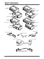
Recorder Controller/Interface
Installation Instructions
AD100 Series
Recorder Controller & Multiple
Interface Hookup / Software
Utility Installation & Operating
Instructions
Contents
Video Recorder Control........................................................... 1
Equipment Description ............................................................ 2
Drawing 1 – System Equipment .............................................. 3
Initial Hookup .......................................................................... 4
Installing the Software Utility ................................................... 4
RIU Programming ................................................................... 4
Drawing 2 – Daisy Chain Configuration ................................... 5
Video Recorder Control
Recorder control hardware and the corresponding utility
software enable an AD1024 or MegaPower 48 system
user to control video recorders at both local and remote
sites. Operators control the video recorders via the
AD2088 keyboard.
Systems developed after AD1024 and MegaPower 48
will also support recorder control. Particular systems
developed before AD1024 can support recorder control
with appropriate upgrade equipment (see the table on
page 8 for details).
The AD Recorder/Controller interface is available for
both 120 VAC and 230 VAC applications.
Equipment Provided (see Drawing 1, Page 3)
Part
Recorder Controller (120 VAC)
Qty
1
Part No.
AD100XA
Recorder Controller (230 VAC)
1
AD100XA-1A
Drawing 3 – AD100 Interface w/ PC & Video Recorders ......... 5
IR Interface Module (120 VAC)
n
AD100IR16
Testing Recorder Commands ................................................. 8
IR Interface Module (230 VAC)
n
AD100IR16-1A
Upgrade Kits and Peripherals ................................................. 8
RL Interface Module (120 VAC)
n
AD100RL8
Drawing 4 – AD100 Interface w/ AD1024 System ................... 9
RL Interface Module (230 VAC)
n
AD100RL8-1
RS-232 Interface Module (120 VAC)
n
AD100RS8
RS-232 Interface Module (230 VAC)
n
AD100RS8-1
Transformer (120 VAC)
n
0650-1772-01
Drawing 5 – AD100 Interface w/ MegaPower 48 System ........ 9
Product Specifications .......................................................... 10
Declaration of Conformity...................................................... 11
Transformer (230 VAC) ***
n
5604-0180-01
If you need assistance…
Recorder Interface Utility
1
0701-14Q1-1D4A
Contact Technical Support at 1-800-392-2873
(or 845-624-7600). Fax: 845-624-7685
Modular Cable
1
6003-0047-02
Adaptor – RJ45 to DB9F
1
2025-0294-01
Adaptor – RJ45 to DB9M
1
2025-0308-01
Velcro Strip
n
0500-5689-01
***
The 230 VAC transformer is equipped with a Euro-style IEC
320 type inlet. A suitable, detachable cord should be
connected between the IEC 320 inlet and power source.
The cord should conform to all national and local code
requirements.
Additional Equipment Required
Additional equipment required for the installation of the
recorder controller/interface network includes:
IBM Compatible PC (Windows 95, 98, & NT)
Video Recorder(s)
IR Remote Device(s)
IR Emitter Cable (Part No. AD100IRE)
RS-232 Cable (Part No. AD100RSC)
Resistive Ladder (RL) Cable (Part No. AD100RLW)
Sub-Miniature 3/32” (2.5mm) Phone Plug (plug required
depending on make and model of RL video recorder
used).
Tools Required
Wire Strippers
Small Slotted Screwdriver
8000-1828-01, Rev. B
SENSORMATIC VIDEO SYSTEMS 1
Equipment Description
The following devices and peripherals are available to
support integrated switching system and video recorder
control (see Drawing 1, page 3 for details).
AD100XA Recorder Controller
The AD100XA is the central processor of a recorder
interface network. A single AD100XA is required for an
entire network. The front side of the AD100XA has a
DB9F connector for RS232 communication. Note: the
connector to the right of the DB9F is not used. The rear
side has a detachable four-position screw terminal
connector that accommodates two power terminals and
A and B terminals for RS485 communication.
Additionally, the rear side has an infrared receive data
sensor for learning IR commands. The top of the
AD100XA contains LEDs for Status, Communications,
and Learn IR activity. Each recorder controller is
supplied with a transformer to power the unit.
The recorder controller enables the programming of the
network’s interface modules (AD100IR16, AD100RL8,
and AD100RS8). Communication between the
controller and interface modules is enabled through the
RS485 protocol. Up to 128 interface modules can be
connected to the controller in a daisy chain
configuration (see Drawing 2, page 5). Note: for each
group of 24 interface modules, an RS485 Repeater
available from other manufacturers is required to drive
the signal to additional units.
AD100 Interface Modules
AD100RL8 Resistive Ladder Module
The AD100RL8 is used to control up to 1024
compatible video recorders via a resistive ladder
network. Up to eight recorders can be controlled with a
single AD100RL8 unit. Each recorder is connected to
one of eight jacks on the interface module via an
AD100RLW resistive ladder cable. (see Drawing 1,
page 3). Note: depending on the make and model of
recorder used, a sub-miniature phone plug may be
required to connect the AD100RLW to the recorder.
AD100RS8 RS-232 Interface Module
The AD100RS8 is used to control up to 1024
compatible video recorders via the RS-232
communications protocol. Up to eight recorders can be
controlled with a single AD100RS8 unit. Each recorder
is connected to the interface module via an AD100RSC
serial cable. (see Drawing 1, page 3). The cable’s RJ-11
plug connects to one of eight jacks on the interface
module
AD100IR16 Infrared Interface Module
The AD100IR16 Interface Module is used to control up
to 2048 compatible video recorders via infrared (IR)
2
Recorder Controller/Interface Installation Instructions
commands. Up to 16 recorders can be controlled with a
single AD100IR16 unit. Each recorder is connected to
the interface module via an AD100IRE IR emitter cable
(see Drawing 1, page 3). The cable’s mini-plug
connects to one of 16 jacks on the interface module.
The plastic shell on the cable’s other end adheres to the
IR sensor on the front of the recorder.
Note: Care must be taken when installing the AD100
interface cables to avoid damage or disconnection of
the cables. Depending on site requirements, cable
management brackets can be used for appropriate
installation of AD100 interface cables.
Controller to Interface Module Communications
Each of the three available interface modules
communicates with the Recorder Controller and other
interface modules via 2-wire, RS-485 communications
protocol set at 9600 Baud.
Additional Interface Module Components
Each of the three available interface modules contains a
detachable, four-position screw terminal connector that
accommodates two power terminals and A and B
terminals for RS-485 communications.
Each module contains a 3/8” diameter hole giving
access to a push button Addressing Switch. The top of
each module contains two LEDs for Power and
Communications indications.
RIU Recorder Interface Utility
In order to implement the programming of the interface
modules, each Recorder Controller is supplied with a
diskette containing the Recorder Interface Utility (RIU)
software.
The RIU utility sets the addresses of the interface
modules, and maps the interface modules to specific
video recorders. Several default recorders featuring
widely used makes and models are provided in the
mapping software. Additionally, the utility enables the
recorder controller to learn a set of basic IR commands
for IR video recorders other than the default models.
Once the recorder controller and interface modules have
been programmed using the RIU utility and an IBM
compatible PC, the recorder controller is then connected
to the Peripheral Interface Port (PIP) of the matrix
system CPU. When appropriately configured, the PIP
will transmit recorder control commands to the system
recorders.
For information on configuring the AD1024 or
MegaPower 48 Peripheral Interface Port, refer to
AD1024 S3 System Setup Software Installation &
Operating Manual, PN 8000-1821-01, AD1024 CPU
System Programming & Operating Instructions, PN
8000-1813-01, or MegaPower 48 System Programming
& Operating Manual, PN 8000-1804-51.
8000-1828-01, Rev. B
AD100 Series System Drawings
Drawing 1 – System Equipment
AD100RS8
Front View
AD100RL8
Front View
Addressing Switch
AD100RS8
Rear View
AD100RL8
Rear View
Addressing Switch
AD100XA
Front View
AD100IR16
Front View
This connector not used
Addressing Switch
AD100XA
Rear View
AD100IR16
Rear View
IR Receive Sensor
AD100RLW Cable
AD100RSC Serial Cable
AD100IRE Emitter Cable
230 VAC Transformer
120 VAC Transformer
Modular Cable with DB9F & DB9M Adaptors
for PC to AD100XA Connection
Drawing 1 – System Equipment
8000-1828-01, Rev. B
Recorder Controller/Interface Installation Instructions
3
Initial Hookup
4.
AD100 series modules can be wall, rack, or desktop
mounted using the supplied Velcro strip.
Launching the Application
On the Windows desktop, click the following sequence:
1. “Start”
2. “Programs”
3. “Sensormatic”
4. “Recorder Installation Utility”
The initial window of the RIU software appears:
1.
2.
3.
4.
Connect the A and B communications terminals of
the AD100XA and all AD100 interface modules in
a daisy chain configuration. (see Drawing 2, Page
5) Use twisted pair, 22 AWG wire, Belden 8442 or
88442 (Plenum), or equivalents. Ensure consistency
in terminal to terminal connections (“A” terminals
should connect only to “A” terminals. “B”
terminals should connect only to “B” terminals.
Never cross-connect power and communication
terminals).
Note: the cables wired at the recorder controller
should be arranged such that they do not cross in
front of, or block the IR receive sensor on the
recorder controller.
Connect the modular cable and adaptors between
the AD100XA and the PC. The cable end with the
DB9M adaptor connects to the recorder controller.
The cable end with the DB9F adaptor connects to
the PC (see Drawing 3, page 5).
Connect transformers to the power terminals of the
AD100XA and the power terminals of each AD100
interface module to be used in the network. The
two transformer wires are non-polarized.
Before connecting the modules’ transformers to
nearby AC outlets, check all system connections.
Installing the Software Utility
1. Install the RIU diskette into the PC’s floppy drive.
2. Click START and RUN.
3. Type “A: \ setup.exe”
4. Press the return (enter) key.
A blue screen appears, followed by four dialog boxes in
sequence:
1. Welcome! (click NEXT).
2. Select Destination Directory (accept or change the
defaults, then click NEXT).
3. Ready to Install (click NEXT).
4. Installation Completed! (click FINISH).
The software is installed. If the defaults are accepted,
the following is true:
1. A group is added to the start menu with the path
Programs\Sensormatic\Recorder Installation
Utility.”
2. A new folder is created with the path “C:\Program
Files\Sensormatic\AD100RIU”.
3. An executable file called “riu.exe” resides in the
AD100RIU folder.
4
Recorder Controller/Interface Installation Instructions
A new folder called “Recorder Library” resides in
the C drive.
RIU Programming
The user can now perform the following actions:
●
Set the addresses for the AD100 interface modules
●
Map the recorder types to be used in the system
(this typically specifies the make and model of the
recorder). The user will either select recorder types
available as pre-programmed default models, or, in
the case of IR recorders, will specify different
recorder types and “learn” the IR command set for
each non-default model.
●
Select module types, and assign recorder types and
recorder numbers to each output of the selected
modules.
●
Save the map file and transfer it from the PC to the
AD100XA.
Auto Addressing Modules
Auto addressing sets the addresses on all of the AD100
interface modules connected in the daisy chain.
1. Select Functions/Controller Setup/Auto Address
Modules. A dialog box appears.
2.
Wait 30 seconds. Press the push-button addressing
switch on the first interface module (press the
8000-1828-01, Rev. B
AD100 Series System Drawings
Drawing 2 – Daisy Chain Configuration
Drawing 2 – Daisy Chain Configuration
Drawing 3 – AD100 Interface w/ PC & Video Recorders
Drawing 3 – AD100 Interface w/ PC & Video Recorders
8000-1828-01, Rev. B
Recorder Controller/Interface Installation Instructions
5
switch with a non-conductive implement such as the
eraser end of a number 2 lead pencil). The dialog box
message will change to “Looking for Module 2”. Press
the addressing switch on the second interface module.
Continue the procedure until all N interface modules
have been addressed.
Note: With each successive module addressed,
additional time is required to find the module. The
search time increases by approximately 5 seconds
for each additional module. For example, when
looking for the fifteenth module, the search time
will be slightly longer than one minute.
3.
When the dialog box message says “Looking for
Module N+1” press the Close button.
Mapping the Recorder Types
With the initial RIU window displayed on the PC
screen, the user must now list the recorder types used in
the system in the window’s left-most “Recorder Types”
column.
The RIU utility comes loaded with several standard
video recorder types. If any or all of the four default IR
models are chosen, it is not necessary to learn IR
commands. If a new recorder type is entered in the
system, the Learning IR Commands procedures that are
discussed in the next section (Mapping Non-Default
Recorder Types) have to be implemented.
To map any of the default types, implement the
following procedure:
1. Click in any row of the left-most Recorder Types
column. The Recorder Library dialog box appears.
non-default model(s) and “learn” the IR command set
appropriate to the model(s).
To map additional recorder types and learn the
appropriate IR command sets, perform the following
steps:
1. Select Functions/Learn IR Commands. The
Recorder Library dialog box again appears (see
illustration under Mapping the Recorder Types).
2. Type an appropriate file name (typically based on
the make and model of the recorder being used) and
save the file. The file will automatically be saved
with the extension “.sir”. Another dialog box
appears:
3.
Aim the remote control device for the chosen
recorder at the built-in IR receive sensor adjacent
to the communication terminals on the AD100XA.
4.
Press the remote control’s PLAY button. The
PLAY dialog box will indicate the signal has been
received, and will prompt for the next remote
command (“RECORD”).
Repeat steps 3 and 4 for each of the remote
commands indicated on the dialog box. The
complete set of commands appears in the following
sequence: “play”, “record”, “rewind”, “fast
forward”, “stop”, “eject”, and “pause”. If the
particular remote control device being used does
not include the button that is “waiting” in the dialog
box, simply press the “Next Command” button to
advance to the next prompt
When all commands have been received, a progress
bar appears next to the “TX” and “RX” buttons in
the upper right-hand portion of the RIU window.
While the transmit and receive buttons flash, the
progress bar advances from zero to 100 percent.
5.
2.
3.
Select the appropriate file and press the Open
button. The file name appears in the selected row of
the left-most Recorder Types column.
Repeat steps 1 and 2 for each default recorder type
in the system.
If only default recorder models are used, proceed to
“Selecting the Module Type” on Page 7.
Mapping Non-Default IR Recorder Types
If the system utilizes IR recorder types other than those
provided as RIU default models, the user must map the
6
Recorder Controller/Interface Installation Instructions
6.
8000-1828-01, Rev. B
7.
When the transmission is finished, the Recorder
In... dialog box appears. Click “OK” to complete
the process.
Assigning Recorder Types to Outputs
Each recorder output must be assigned a recorder type
and a recorder number.
1. To assign a recorder type to an output, click on the
appropriate selection in the left-most Recorder
Types column. The Recorder Library dialog box
appears.
2. Press Cancel.
3. Click in the right-most Recorder Types column in
the row adjacent to the appropriate output number
(click and drag to assign the selected recorder type
to multiple outputs).
4. Click on the arrow in the center of the initial RIU
window.
The selected recorder type will appear to the right of the
appropriate output(s).
8.
Repeat steps 1 through 7 for each non-default
recorder type being used in the system.
Note: Some users may prefer to perform the above
procedure in subdued lighting conditions for optimal
results.
Assigning Recorder Numbers to Outputs
1.
To assign a recorder number, click in the Recorder
# cell to the right of the appropriate output. The
Enter Recorder # dialog box appears.
2.
Use the up or down arrows to the right of the spin
box to select a recorder number. Resistive Ladder
and RS-232 recorders can have any number up to
1024. IR recorders can have any number up to
2048.
Press the OK button. The number will appear in the
selected cell.
Selecting the Module Type
1. Click the appropriate Module # row in the Module
# column. The Select Module Type dialog box
appears.
2.
If the Infra-Red option is selected and the OK
button is clicked, a column of 16 outputs opens up
below and to the right of the selected module
number. If either the Resistor Ladder or the ASCII
(RS-232) option is selected, a column of eight
outputs opens up below and to the right of the
selected module number.
3.
Saving the Map File / Data Transfer
1.
2.
Resistive Ladder / RS-232 Option
After selecting the recorder and module types, and
assigning recorder types and numbers to the
module outputs, select File/Save As. The Recorder
Library dialog box appears. Name the map file
appropriately and click the Save button.
Select Functions/Controller Setup/Transfer Setup
to AD100XA. A progress bar will appear and
advance from zero to 100 percent, indicating that
the recorder interface data has been transferred
from the PC to the AD100XA.
IR Option
8000-1828-01, Rev. B
Recorder Controller/Interface Installation Instructions
7
Testing Recorder Commands
Testing IR Commands via PC
Prior to final hookup of the AD1024 or MegaPower 48
system with recorder interface hardware, it is advisable
to test the IR command set with the system video
recorders in a “test bench” setting.
This will verify the proper operation of the recorder
interface modules while isolating the test from the
physical complexities of the actual site installation.
Connecting the IR Emitter Cables
1. Connect the IR emitter cable mini-plugs into the
appropriate IR jacks on the AD100IR16 modules.
Note: the module’s 16 IR connectors are labeled
IR-1 through IR-16 (see Drawing 3, page 5).
2. Attach the adhesive emitter to the appropriate
location on the video recorder under test. If
necessary, consult the recorder manufacturer’s
instructions to verify the proper location.
Testing the Recorder Command Set
1. Select Functions/Test Recorder Commands. The
Test Recorder dialog box appears.
Settings for the PIP are as follows:
Baud rate
2.
9600
Data Bits
8
Stop Bits
1
Parity
None
Using the AD2088 keyboard, call up each of the
system video recorder and test each of the recorder
command functions (see Drawing 4 or 5, page 9).
Notes on Controller Setup Functions
When the Functions menu is selected, Controller Setup
provides two options in addition to the two already
discussed:
●
●
Comm Port enables the user to choose COMM 1, 2,
3, or 4 on the PC used for system setup.
Default IR Frequency – Typical video recorders are
set to an IR frequency of 38 KHz. If a recorder
manufacturer’s specifications indicate a different
frequency, the Default IR Frequency dialog box
enables the user to set a value ranging from 20 to
150 KHz.
Upgrade Kits and Peripherals
The following table lists the upgrade kits and
peripherals that are required for the applicable AD
matrix switcher/controller systems to accommodate
video recorder control operations:
2.
3.
Using the up and down arrows to the right of the
spin box, set the recorder # to a value between 1
and 2048. Test the seven recorder command
functions by pressing the command buttons in
sequence.
Repeat step 2 for each recorder in the system, or, if
the number of system recorders is large and the
time allotted for testing is limited, randomly select
a smaller sub-set of the total number of recorders
and test their command functions.
Testing Commands with AD1024 or MP48
1. After testing the recorder commands with the PC,
disconnect the serial cable from the PC COM port.
Disconnect the DB9F adaptor from the modular
cable. Connect the RJ-45 connector to the RS-232
Peripheral Interface Port (PIP) of the AD1024 CPU
or MegaPower 48 patch panel.
8
Recorder Controller/Interface Installation Instructions
Matrix Switcher/Controller System
Required Upgrade Kits & Peripherals
MegaPower 48 Video Routing System
None required
AD1024 MegaPower II Matrix
Switcher/Controller System
None required
AD2050 MegaPower II Matrix
Switcher/Controller System
●
AD1024CPUKIT Upgrade Kit for
existing AD1996CPU
●
●
●
●
AD2088 Full System Keyboard
AD2052 MegaPower II WIP Matrix
Switcher/Controller System
●
●
●
AD2088 Full System Keyboard
●
●
●
AD1024S3 System Setup Software
AD1995 MegaPower Matrix
Switcher/Controller System
AD1024CPU MegaPower CPU
AD1024S3 System Setup Software
AD2010DB Data Receiver/Buffer for
AD2010R and AD2020R Bays
AD1024CPU MegaPower CPU
Firmware
for
AD1625R Bays
AD1609R
and
AD2088 Full System Keyboard
Other Components must be
specified by Applications
Engineering.
8000-1828-01, Rev. B
Drawing 4 – AD100 Interface w/ AD1024 System
Drawing 4 – AD100 Interface w/ AD1024 System
AD100XA
AD1024 CPU
AD100IR16
AD100RS8
AD2088 Keyboard
IR Video
Recorders
Integra Digital Video Recorder
Note: System shown with AD100XA,
AD100IR16, and AD100RS8 Modules.
AD100RL8 not shown.
Drawing 5 – AD100 Interface w/ MegaPower 48 System
Drawing 5 – AD100 Interface w/ MegaPower 48 System
MegaPower 48 Patch Panel
AD2088 Keyboard
AD100IR16
AD100XA
IR Video Recorders
Note: System shown with AD100XA and AD100IR16
Modules. AD100RS8 and AD100RL8 not shown.
8000-1828-01, Rev. B
Recorder Controller/Interface Installation Instructions
9
Product Specifications
Environmental Specifications
Electrical Specifications
Operating Temp:
5°C to 40°C(40°F to 104°F)
Humidity:
95° non-condensing
Storage Temp:
-40°C to 70°C (-40°F to 155°F)
Power Supply Input
Power Source: AD100XA
AD100IR16
120 VAC, 60 Hz
120 VAC, 60 Hz
AD100XA-1A 230 VAC, 50/60 Hz
AD100IR16-1A 230 VAC, 50/60 Hz
AD100RL8
120 VAC, 60 Hz
AD100RL8-1
230 VAC, 50/60 Hz
AD100RS8
120 VAC, 60 Hz
AD100RS8-1
230 VAC, 50/60 Hz
Power Supply Output
Output Voltage: 9-12 VAC @ 0.5 A max. 120 V
9-12 VAC @ 0.5 A max. 230 V
AD100XA/(-1) Drive Capability
Max RS485 Distance:
4000 ft.
Max Number or RS485 Loads:
24 loads
Mechanical Specifications
Mounting:
Desktop, Wall, or Rack,
using mounting holes or
Velcro strips.
Weight:
5 oz.
Color (Plastic Housing):
Black
Approvals
UL:
UL listed transformer with device
CSA:
CSA certified transformer provided w/ device
CE:
CE marked transformer provided with device
Warranty Disclaimer
Sensormatic Electronics Corporation makes no
representation of warranty with respect to the contents
hereof and specifically disclaims any implied warranties
of merchantability or fitness for any particular purpose.
Further, Sensormatic Electronics Corporation reserves
the right to revise this publication and make changes
from time to time in the content hereof without
obligation of Sensormatic Electronics Corporation to
notify any person of such revision or changes.
Dimensions:
AD100XA(-1A):
Length:
6.50 in.
Width:
3.75 in.
Height:
1.38 in.
AD100IR16(-1A):
Length:
5.50 in.
Width:
3.25 in.
Height:
1.38 in.
AD100RL8(-1):
Length:
5.50 in.
Width:
3.25 in.
Height:
1.38 in.
AD100RS8(-1):
10
Length:
6.50 in.
Width:
3.75 in.
Height:
1.38 in.
Recorder Controller/Interface Installation Instructions
8000-1828-01, Rev. B
Declaration of Conformity
Declaration of Conformity
Manufacturer’s Name:
Sensormatic Electronics Corporation
Manufacturer’s Address:
1 Blue Hill Plaza
nd
2 Floor
Pearl River, New York, 10965 USA
Declares, that the products listed below:
Name/Type:
AD100 Series Recorder Interface Modules
Model Numbers:
AD100XA-1A, AD100IR16-1A, AD100RL8-1, AD100RS8-1
comply with all applicable directives as demonstrated by conformance to the following Product Specifications:
Safety:
EN 60950: 1992
EMC:
EN 50130-4: 1995
EN 55022: 1994, Class B
EN 61000-3-2: 1995
EN 61000-3-3: 1995
EN 61000-4-2: 1995
EN 61000-4-3: 1996
EN 61000-4-4: 1995
EN 61000-4-5: 1995
EN 61000-4-6: 1996
EN 61000-4-11: 1994
Supplementary Information:
The products herewith comply with the requirements of the Low Voltage Directive, 73/23/EEC as amended by 93/68/EEC, and the
EMC Directive, 89/339/EEC as amended by 93/68/EEC.
Pearl River, NY, USA
15 January, 2001
Harold D. Johnson, Ph.D.
Director of Engineering
European Contact: Sensormatic France S.A.
7, rue Alexis de Tocqueville, Parc de Haute Technologie, 92183 ANTONY CEDEX
8000-1828-01, Rev. B
Recorder Controller/Interface Installation Instructions
11
Sensormatic Video Systems Division
1 Blue Hill Plaza
Pearl River, New York, 10965
(845) 624-7600
PN 8000-1828-01, Revision B
12
Recorder Controller/Interface Installation Instructions
8000-1828-01, Rev. B