1
DTP T FB 332 and DTP T FB 232 • Setup Guide (Continued)
Ridges
Captive
Screw
Connector
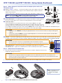
Power (see figure 1 on page 1) — Connect the included 12 VDC power supply to either unit,
transmitter or receiver, as shown at right. Use the included tie-wrap to strap the cord to the
captive screw connector.
NOTE: If the TP switch (C) is in DTP, one power supply can power both units.
If the switch is in HDBT, each unit requires its own power supply.
B
Remote RS-232 port — For serial RS-232 control, connect a host device or control system to
the 3.5 mm, 3-pole captive screw connector. The wiring and protocol are shown at right.
C
TP function switch —
If the receiving device is in the Extron DTP series, set this switch to DTP. The TP output
consists of HDMI with embedded audio, analog audio, RS-232 and IR, and remote power. The
transmitter and receiver can be powered by one 12 VDC power supply connected to either unit.
3"
16 (5 mm) MAX
SECTION A–A
Power Supply A
Output Cord
A
G
Connect an IEC power cord between the power supply and a 100-240 VAC, 50-60 Hz source.
REMOTE
RS-232
A
Smooth
Rx Tx
Step 3 — Make side panel connections under the adapter plates and set the
TP function switch
3"
16 (5 mm) MAX
RS-232 Device • 9600 Baud
• 8 data bits
• No parity
• 1 stop bit
Tx Rx Gnd
For an HDBaseT-enabled receiver type, set this switch to HDBT position. The TP output consists of HDMI with embedded audio plus
RS-232 and IR. The transmitter and receiver each requires its own 12 VDC power supply.
ATTENTION:
• Position this switch BEFORE connecting the appropriate device to the TP connector. Failure to comply can damage the
endpoint.
• Positionnez le sélecteur AVANT de connecter l’appareil approprié au connecteur TP. Ne pas respecter cette procédure
pourrait endommager le point de connexion.
D
Out port— Connect the Out (RJ-45) port to the DTP In port on the receiver. Extron recommends that you terminate both cable ends in
accordance with the following, at a minimum: TIA/EIA T 568B and 24 AWG, solid conductor, shielded cable with 400 MHz bandwidth.
Pins:
12345678
ATTENTION:
• Do not connect this connector to a computer data or telecommunications network.
• Ne connectez pas ces port à des données informatiques ou à un réseau de télécommunications.
TIA/EIA T
568B
Pin Wire color
1 White-orange
2
3
White-green
Link LED indicator — Lights when a valid link between a DTP or HDBT input and output is established.
4
Blue
5
White-blue
Green
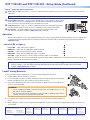
Step 4 — Mount the unit in the floor box
a.
Orange
Signal LED indicator — Lights when the device is transmitting a video signal or a test pattern.
6
Place the DTP T FB unit in the desired position in the floor box so that the side panel connectors face
towards the opening of the floor box.
TP Wires
7
White-brown
8
Brown
ATTENTION:
• Ensure there is enough space between the top panel connectors and the lid of the floor box so the lid fully closes.
• Assurez vous qu’il y ait assez d’espace entre les connecteurs du panneau supérieur et le couvercle du boîtier de sol afin
que celui-ci puisse se fermer entièrement.
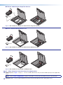
b. Using the provided self-threading screws, secure the DTP T FB unit to the adapter plates (see figures 2 through 5).
Ackermann GB3 (OBO Betterman) floor box
DT
PT
FB
33
2
DT
PT
PO
12VWER
A MA RE
X RSMO
-23TE
2
- +
995242
2
995241
G
Rx
Tx
XT
P OU
T
Figure 2. DTP T FB Unit in an Ackermann GB3 (OBO Betterman) Floor Box
FB
33
2
NOTE: For position 2, install
adapter plate 995242 to
one of the other adapter
plates.