1
®
SynOptics Series 3000 Hub
Management Module Guide
Notice
Cabletron Systems reserves the right to make changes in specifications and other information
contained in this document without prior notice. The reader should in all cases consult Cabletron
Systems to determine whether any such changes have been made.
The hardware, firmware, or software described in this manual is subject to change without notice.
IN NO EVENT SHALL CABLETRON SYSTEMS BE LIABLE FOR ANY INCIDENTAL,
INDIRECT, SPECIAL, OR CONSEQUENTIAL DAMAGES WHATSOEVER (INCLUDING BUT
NOT LIMITED TO LOST PROFITS) ARISING OUT OF OR RELATED TO THIS MANUAL OR
THE INFORMATION CONTAINED IN IT, EVEN IF CABLETRON SYSTEMS HAS BEEN
ADVISED OF, KNOWN, OR SHOULD HAVE KNOWN, THE POSSIBILITY OF SUCH
DAMAGES.
Copyright © February 1998, by Cabletron Systems, Inc. All rights reserved.
Printed in the United States of America.
Order Number: 9030920 E6
Cabletron Systems, Inc.
P.O. Box 5005
Rochester, NH 03866-5005
SPECTRUM, the SPECTRUM IMT/VNM logo, DCM, IMT, and VNM are registered
trademarks, and SpectroGRAPH, SpectroSERVER, Inductive Modeling Technology,
Device Communications Manager, and Virtual Network Machine are trademarks of
Cabletron Systems, Inc.
C++ is a trademark of American Telephone and Telegraph, Inc.
UNIX is a trademark of The Open Group.
OSF/Motif and Motif are trademarks of the Open Software Foundation, Inc.
X Window System is a trademark of The Open Group.
Ethernet is a trademark of Xerox Corporation.
9030920 E6
i
Virus Disclaimer
Cabletron Systems makes no representations or warranties to the effect that the Licensed
Software is virus-free.
Cabletron has tested its software with current virus checking technologies. However, because no
anti-virus system is 100% reliable, we strongly caution you to write protect and then verify that
the Licensed Software, prior to installing it, is virus-free with an anti-virus system in which you
have confidence.
Restricted Rights Notice
(Applicable to licenses to the United States Government only.)
1. Use, duplication, or disclosure by the Government is subject to restrictions as set forth in
subparagraph (c) (1) (ii) of the Rights in Technical Data and Computer Software clause at
DFARS 252.227-7013.
Cabletron Systems, Inc., 35 Industrial Way, Rochester, New Hampshire 03866-5005.
2. (a) This computer software is submitted with restricted rights. It may not be used,
reproduced, or disclosed by the Government except as provided in paragraph (b) of this
Notice or as otherwise expressly stated in the contract.
(b) This computer software may be:
(c)
(1)
Used or copied for use in or with the computer or computers for which it was
acquired, including use at any Government installation to which such computer or
computers may be transferred;
(2)
Used or copied for use in a backup computer if any computer for which it was
acquired is inoperative;
(3)
Reproduced for safekeeping (archives) or backup purposes;
(4)
Modified, adapted, or combined with other computer software, provided that the
modified, combined, or adapted portions of the derivative software incorporating
restricted computer software are made subject to the same restricted rights;
(5)
Disclosed to and reproduced for use by support service contractors in accordance with
subparagraphs (b) (1) through (4) of this clause, provided the Government makes
such disclosure or reproduction subject to these restricted rights; and
(6)
Used or copied for use in or transferred to a replacement computer.
Notwithstanding the foregoing, if this computer software is published copyrighted
computer software, it is licensed to the Government, without disclosure prohibitions, with
the minimum rights set forth in paragraph (b) of this clause.
(d) Any other rights or limitations regarding the use, duplication, or disclosure of this
computer software are to be expressly stated in, or incorporated in, the contract.
(e)
ii
This Notice shall be marked on any reproduction of this computer software, in whole or in part.
SynOptics Series 3000 Hub
Management Module Guide
Contents
Preface
What is in this Guide............................................................................................................ xi
Terminology.......................................................................................................................... xii
Conventions ........................................................................................................................ xiii
Related SPECTRUM Documentation................................................................................ xiii
Other Related Documentation ........................................................................................... xiv
Chapter 1
Introduction
What is in this Chapter ...................................................................................................... 1-1
SynOptics 3000 Series Hubs .............................................................................................. 1-1
SPECTRUM Model Type.................................................................................................... 1-1
Supported Mibs................................................................................................................... 1-5
Accessing SPECTRUM Views ............................................................................................ 1-6
Roadmap of SPECTRUM Views ........................................................................................ 1-8
Chapter 2
Device View
What is in this Chapter ...................................................................................................... 2-1
Logical Device View ............................................................................................................ 2-1
Ethernet Module Icon .................................................................................................. 2-3
Module Identification Labels ................................................................................ 2-3
Module Icon Subviews Menu Selections............................................................... 2-4
Port Icon ................................................................................................................. 2-4
Port Icon Subviews Menu Selections.................................................................... 2-4
Token Ring Module Icon .............................................................................................. 2-5
Module Identification Labels ................................................................................ 2-6
Module Icon Subviews Menu Selections............................................................... 2-6
Port Icons ............................................................................................................... 2-7
Port Icon Subviews Menu Selections.................................................................... 2-7
FDDI Module Icon........................................................................................................ 2-8
Module Identification Labels ................................................................................ 2-8
Module Icon Subviews Menu Selections............................................................... 2-9
Port Icon ................................................................................................................. 2-9
Port Icon Subviews Menu Selections.................................................................. 2-10
Physical Device View ........................................................................................................ 2-10
9030920 E6
iii
Chapter 2
Device View (continued)
Bridge Device View ...........................................................................................................2-12
Bridge Interface Icon ..................................................................................................2-13
Interface Number Label.......................................................................................2-14
Administrative Status Label ...............................................................................2-14
Port Type Label ....................................................................................................2-14
MAC Address Label .............................................................................................2-15
Network Information Label .................................................................................2-15
Gauge Label..........................................................................................................2-15
Interface Options Panel..............................................................................................2-16
Gauge Control Panel ..................................................................................................2-16
Chapter 3
Configuration Views
What is in this Chapter ......................................................................................................3-1
NMM Nodes.........................................................................................................................3-2
SynOptics Token Ring Show Nodes Table View..........................................................3-2
SynOptics Token Ring Find Nodes Table View ...........................................................3-3
Ethernet Configuration ......................................................................................................3-4
SynOptics Ethernet Frames and Errors View ............................................................3-4
SynOptics Ethernet Frame Sizes and Protocols View ................................................3-5
SynOptics Ethernet NMM Table View ........................................................................3-5
SynOptics Ethernet Host Table View ..........................................................................3-5
SynOptics Ethernet Threshold Table View .................................................................3-6
Add Threshold ......................................................................................................3-10
Token Ring Configuration................................................................................................. 3-11
SynOptics Token Ring Station Table View................................................................ 3-11
SynOptics Token Ring Total Errors Table View........................................................3-12
SynOptics Token Ring Station Isolating Errors View ..............................................3-12
SynOptics Token Ring Station Non-Isolating Errors View ......................................3-13
SynOptics Token Ring NMM Topology Table View...................................................3-14
SynOptics Token Ring NMM Configuration View ....................................................3-14
FDDI Configuration ..........................................................................................................3-15
SynOptics FDDI NMM Ring Status View .................................................................3-15
SynOptics FDDI NMM Station Worst Errors View ..................................................3-16
SynOptics FDDI NMM SRF Event Counters View ..................................................3-16
SynOptics FDDI NMM SRF Condition View ............................................................3-17
SynOptics FDDI NMM Ring Topology View .............................................................3-17
SynOptics Physical Topology Trunk View .................................................................3-18
SynOptics Physical Topology Node View...................................................................3-18
SynOptics NMM Optical Bypass Switch View..........................................................3-19
Device Configuration ........................................................................................................3-20
SynOptics Configuration View...................................................................................3-20
SynOptics Agent Download View ..............................................................................3-20
Current Information ............................................................................................3-21
Next Boot ..............................................................................................................3-21
SynOptics Agent Protocol Configuration View .........................................................3-22
SynOptics Agent Configuration View ........................................................................3-24
SynOptics Agent Hardware View ..............................................................................3-25
SynOptics IP Trap Receiver View ..............................................................................3-26
SynOptics IPX Trap Receiver View ...........................................................................3-27
iv
SynOptics Series 3000 Hub
Management Module Guide
Chapter 3
Configuration Views (continued)
SynOptics Chassis Configuration View........................................................................... 3-27
Module Configuration Table ...................................................................................... 3-28
SynOptics Module Configuration View .............................................................. 3-29
SynOptics Redundant Power Supply View ............................................................... 3-30
SynOptics Ethernet Local Bridge Configuration View................................................... 3-31
SynOptics Ethernet Local Bridge Range Table ........................................................ 3-32
SynOptics Ethernet Local Bridge Spanning Tree Configuration ............................ 3-33
Spanning Tree Port Data .................................................................................... 3-34
SynOptics Ethernet Local Bridge Filter Table ......................................................... 3-34
Chapter 4
Event and Alarm Messages
What is in this Chapter ...................................................................................................... 4-1
SynOptics Series 3000 Events and Alarms....................................................................... 4-1
Chapter 5
Application View
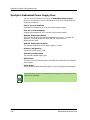
What is in this Chapter ...................................................................................................... 5-1
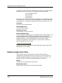
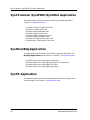
Syn3 Common /Syn3FDDI/Syn3Stck Application ............................................................ 5-2
Syn3EnetBdg Application .................................................................................................. 5-2
SynTR Application.............................................................................................................. 5-2
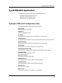
Syn3FDDISMT Application ............................................................................................... 5-3
SynOptics FDDI SMT Configuration View................................................................. 5-3
SynOptics FDDI SMT Parameters View .................................................................... 5-4
SynOptics FDDI SMT LER Thresholds Table View................................................... 5-5
SynFDDIMAC Application................................................................................................. 5-6
SynOptics FDDI MAC Configuration View ................................................................ 5-6
SynOptics FDDI MAC Parameters View .................................................................... 5-7
SynOptics FDDI MAC Performance View .................................................................. 5-8
SynOptics FDDI MAC Detail View ............................................................................. 5-8
SynOptics FDDI MAC Station Table View ................................................................. 5-9
9030920 E6
v
vi
SynOptics Series 3000 Hub
Management Module Guide
Figures
Chapter 1
Figure 1-1.
Figure 1-2.
Figure 1-3.
Figure 1-4.
Chapter 2
Figure 2-1.
Figure 2-2.
Figure 2-3.
Figure 2-4.
Figure 2-5.
Figure 2-6.
Figure 2-7.
Figure 2-8.
Introduction
Using Double-Click Zones to Access SPECTRUM Views ................................... 1-6
Accessing Icon Subviews Menus from the Device Icon ....................................... 1-7
Accessing Icon Subviews Menus from Labels ..................................................... 1-7
SPECTRUM Views Roadmap .............................................................................. 1-8
Device View
Logical Device View .............................................................................................. 2-2
Ethernet Module Icon ........................................................................................... 2-3
Token Ring Module Icon ....................................................................................... 2-5
FDDI Module Icon ................................................................................................ 2-8
Physical Device View .......................................................................................... 2-11
Bridge Device View ............................................................................................. 2-12
Interface Icon ...................................................................................................... 2-13
Gauge Control Panel .......................................................................................... 2-17
9030920 E6
vii
viii
SynOptics Series 3000 Hub
Management Module Guide
Tables
Chapter 1
Table 1-1.
Table 1-2.
Table 1-3.
Table 1-4.
Table 1-5.
Chapter 2
Table 2-1.
Table 2-2.
Table 2-3.
Table 2-4.
Table 2-5.
Table 2-6.
Table 2-7.
Table 2-8.
Table 2-9.
Table 2-10.
Chapter 3
Table 3-1.
Chapter 4
Table 4-1.
Introduction
Supported Ethernet Model Types ......................................................................... 1-2
Supported Token Ring Model Types..................................................................... 1-3
Supported FDDI Model Types .............................................................................. 1-4
Supported Bridge Model Types............................................................................. 1-5
Supported MIBs ..................................................................................................... 1-5
Device View
Module Icon Subviews Menu ............................................................................... 2-4
Ethernet Port Menu Selections............................................................................. 2-5
Module Icon Subviews Menu ............................................................................... 2-6
Token Ring Port Menu Selections ........................................................................ 2-7
Module Icon Subviews Menu ............................................................................... 2-9
FDDI Port Menu Selections ................................................................................ 2-10
Administrative Status for the Physical Application .......................................... 2-14
Administrative Status for the Bridging Application ......................................... 2-14
Rate Gauge Mode: Attributes and Corresponding Color ................................... 2-18
Totals Gauge Mode: Attributes and Corresponding Color ................................ 2-18
Configuration Views
Threshold Condition .............................................................................................. 3-8
Event and Alarm Messages
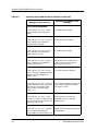
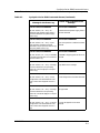
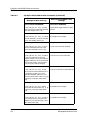
SynOptics Series 3000 Events and Alarms.......................................................... 4-1
9030920 E6
ix
x
SynOptics Series 3000 Hub
Management Module Guide
Preface
Use this guide if you are going to manage any SynOptics 3000 Series Hub
through SPECTRUM. Before reading this guide, you should be familiar with
SPECTRUM’s functions. You should also be familiar with any network
management and hardware requirements described in the related SynOptics
hub documentation.
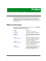
What is in this Guide
The following chapter descriptions outline the organization of the SynOptics
3000 Series Management Module Guide:
Chapter
Description
Chapter 1
Introduction
Describes the SynOptics hub
management module and model types.
Chapter 2
Device View
Describes the Device View’s logical and
physical representation of a SynOptics
hub.
Chapter 3
Configuration Views
Describes the Configuration Views for
the SynOptics 3000 Series hub models,
which provide network management
information for the device.
Chapter 4
Configuration Views
Contains a listing and explanation of the
event/alarm messages generated in the
Event Log and Alarm View for the
SynOptics hub model types.
Chapter 5
Application View
Describes the Application View for the
SynOptics 3000 Series hub models and
the major and minor application
information provided by the view.
9030920 E6
xi
Terminology
Terminology
This section defines several terms used in this guide to describe the SynOptics
hub model types.
Hub
For the purposes of this guide, the general term hub replaces the term
concentrator in representing SynOptics devices.
Hub Chassis
The software model representation of the SynOptics hub (4 or 12 slots) with
no modules installed in any of its slots.
Media Interface Modules
The software model representations of modules installed in a SynOptics hub
chassis. There are two types of Modules: Intelligent Modules and NonIntelligent Modules.
Intelligent Modules
Modules that provide network management functions and network media
interfacing. These are also referred to as NMM - network management
modules.
Non-intelligent Modules
Modules that provide interfaces to different kinds of network media, but have
no network management capabilities.
Refer to the specific SynOptics hardware manual for a detailed description of
your particular SynOptics hub or module.
Preface
xii
SynOptics Series 3000 Hub
Management Module Guide
Conventions
Conventions
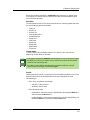
This guide uses the following conventions:
• Menu selections and buttons referenced in text appear in bold; for
example, Configuration or Detail.
• Button names appear in shadowed boxes when introducing paragraphs
describing their use; for example:
Help
• Menu navigation appears in order of selection; for example, Icon
Subviews -> Utilities -> Application.
• Referenced chapter titles and section headings appear in italics.
• Referenced documents appear in bold italics.
• Hypertext links are blue for online documents.
• SynOptics 3000 Series Hub is referred to as “device.”
Related SPECTRUM Documentation
Refer to the following documentation for more information on managing with
SPECTRUM:
Routing Services Management Module Guide
Report Generator User’s Guide
Getting Started With SPECTRUM for Operators
Getting Started With SPECTRUM for Administrators
How To Manage Your Network With SPECTRUM
9030920 E6
Preface
xiii
Other Related Documentation
Other Related Documentation
Refer to the following documentation for more information on managing
TCP/IP-based networks:
Martin, James, Kathleen Kavanagh Chapman, Joe Leben. Local Area
Networks: Architectures and Implementations, 2d ed. Englewood Cliffs,
NJ: Prentice Hall, 1994.
Rose, Marshall T. The Simple Book: An Introduction to Management of
TCP/IP-based Internets. Englewood Cliffs, NJ: Prentice Hall, 1991.
Stallings, William. Data and Computer Communications, 4th ed. New
York: Macmillan Publishing Company, 1994.
Tanenbaum, Andrew S. Computer Networks, 3d ed. Englewood Cliffs, NJ:
Prentice Hall, 1996.
Preface
xiv
SynOptics Series 3000 Hub
Management Module Guide
Chapter 1
Introduction
What is in this Chapter
This chapter introduces the SPECTRUM Management Module for SynOptics
Model 3000 Series hubs. It describes the following:
•
•
•
•
SynOptics 3000 Series Hubs
SPECTRUM Model Type
Accessing SPECTRUM Views
Roadmap of SPECTRUM Views
SynOptics 3000 Series Hubs
The SynOptics 3000 Series Hubs are 12 (3000) and 4 (3030) slot concentrators.
Table 1-1through Table 1-4 list the modules based on technology that are
installed in the concentrators above.
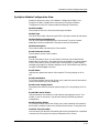
SPECTRUM Model Type
The model type refers to the management module software package used to
specify attributes, actions, and associations for the physical device using the
Simple Network Management Protocol (SNMP) and Management Information
Bases (MIBs). The following section details the different model types provided
by this management module, and describes the supported physical modules
corresponding to each model type.
9030920 E6
1-1
SPECTRUM Model Type
HubSynSer3xxx
This model type represents the SynOptics Model 3000 Ethernet hub series of
devices. Table 1-1 provides a list of supported Ethernet models and their
descriptions.
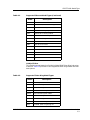
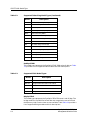
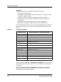
Table 1-1.
Supported Ethernet Model Types
Model
Introduction
1-2
Description
3040
Network control engine (Sparc)
3040s
Network control engine (Sparc)
3100r
Summing module
3174
Workstation Controller
3301
Ethernet ThinNet host module
3301_75
Thin net ether host module
3301_93
Thin net ether host module
3302
Shielded twisted pair ether host module
3304a
10BASE-F host module
3304st
Ether fiber host module
3305
UTP Ethernet host module
3307
UTP Ethernet 50 pin host module
3307a
Ether host module with amp
3307hd
UTP Ethernet 50 pin host module
3308
Ether host module
3308a
Ether host module
3308b
10BASE-T Ethernet host module
3313
Ether AUI NMM with RS232 port
3313a
Ether AUI NMM with RS232 port
3313m
Ether AUI NMM with modem
3313s
Ether AUI NMM with modem
3313sa
Ethernet NMM (super agent)
3314a
Ether FOIRL NMM w/RS232 port
3314s
Ether FOIRL NMM with modem
3314sa
Ethernet FOIRL NMM (super agent)
3314st
Ether FOIRL NMM w/RS232 port
SynOptics Series 3000 Hub
Management Module Guide
SPECTRUM Model Type
Table 1-1.
Supported Ethernet Model Types (Continued)
Model
Description
3314mst
Ether FOIRL NMM with modem
331x
Ether NMM w/unknown MDA type
3323
Ether AUI local bridge
3328
Ethernet Switching Engine
3333
Ethernet AUI retiming module
3334st
Ethernet FOIRL retiming module
3356
Ether remote bridge
3368
10BASE-T Ethernet host module
3383
Ether AUI local router
3384
Ether FOIRL local router
3386
cisco remote router
3394
Ether-localtalk router
3395
Xyplex terminal server
3395a
Xyplex terminal server
HubSynTR3xxx
This model type represents the SynOptics Model 3000 Token Ring hub series
of devices. Table 1-2 provides a list of supported Token Ring models and their
descriptions.
Table 1-2.
Supported Token Ring Model Types
Model
9030920 E6
Description
3100r
Summing module
3502
STP Token Ring host module
3502a
STP Token Ring host module
3502b
STP/UTP Token Ring host module
3504-st
Fiber Token Ring host module
3505
UTP Token Ring host module
3505a
UTP Token Ring host module
3505b
UTP/STP Token Ring host module
3512
TR NMM w/STP ring in/ring out
Introduction
1-3
SPECTRUM Model Type
Table 1-2.
Supported Token Ring Model Types (Continued)
Model
Description
3512s
TR NMM w/STP ring in/ring out
3513
STP Token Ring NMM
3513s
STP TR repeater NMM
3513sa
Token Ring NMM (super agent)
3514st
Fiber Token Ring NMM
3514s
TR NMM w/FOIRL ring in/ring out
3517sa
Fiber/STP Token Ring NMM (super agent)
351x
TR NMM module w/unknown MDA type
3522
STP Token Ring Local Bridge
3522a
TR Local Bridge
3532
STP Token Ring ring in/ring out module
3534
FOIRL repeater
3552
STP ring in/ring out module
3554
FOIRL ring in/ring out module
HubSyn3FDDI
This model type represents the SynOptics FDDI 3000 series of devices. Table
1-3 provides a list of supported FDDI models and their descriptions.
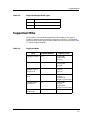
Table 1-3.
Supported FDDI Model Types
Model
Description
3904
Multi-mode Fiber FDDI Host module
3904-2sm
Single-mode Fiber FDDI Host module
3905
UTP FDDI Host module
3910s
Multi-mode Fiber FDDI NMM
3910s-sm
Single-mode Fiber FDDI NMM
BdgSyn332xS
This model type represents the SynOptics 332xS Ethernet Local Bridge. The
bridge module in the 3000 Series hub does not recognize the rest of the hub,
therefore any Hub Chassis views are not available. Table Table 1-4 provides a
list of supported Bridge models and their descriptions.
Introduction
1-4
SynOptics Series 3000 Hub
Management Module Guide
Supported Mibs
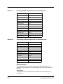
Table 1-4.
Supported Bridge Model Types
Model
Description
3323s
Ethernet AUI high speed local bridge
3324-st
Ethernet FOIRL high speed local bridge
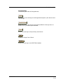
Supported Mibs
The SynOptics Series 3000 Management Module supports four types of
models to represent both the physical hub and its interfaces. The following
sections provide a description of these models and how they are related. Table
1-5 lists the supported MIBs.
Table 1-5.
Supported MIBs
MIB
9030920 E6
Release Number
Imports From
SynOptics Common
4.2.0
RFC1155-SMI
RFC1213-MIB
RFC-1212
SynOptics Ethernet
4.1
RFC-1213-MIB
RFC-1155-SMI
RFC-1212
SynOptics Basic
Ethernet & Token
Ring 2K & 3K
N/A
RFC1155-SMI
RFC-1212
RFC-1215
SynOptics Token
Ring
4.0.2
RFC1155-SMI
RFC-1212
RFC1213-MIB
SynOptics-Common-MIB
SynOptics FDDI
Concentrator
2.1.2
RFC1155-SMI
RFC-1212
RFC1213-MIB
SynOptics-Common-MIB
SynOptics Ethernet
Local Bridge
N/A
RFC1065-SMI
Introduction
1-5
Accessing SPECTRUM Views
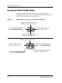
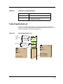
Accessing SPECTRUM Views
Icons provide access to SPECTRUM views that display device-specific
information. Access these views through double-click zones (Figure 1-1) and
Icon Subviews menus (Figure 1-2 and Figure 1-3).
Figure 1-1.
Using Double-Click Zones to Access SPECTRUM Views
Accesses the Configuration view; see
Chapter 3, Configuration Views.
Model Name
Accesses the Device Topology view;
refer to SPECTRUM Views.
Accesses a Device view; see
Chapter 2, Device View.
Hub_SynSer3xxx
Accesses the Application view; see
Chapter 5, Application View.
Accesses the Configuration view; see
Chapter 3, Configuration Views.
Accesses a Device view; see
Chapter 2, Device View.
Model Name
Accesses the Performance view;
refer to the SPECTRUM Views.
Hub_SynSer3xxx
Accesses the Device Topology view;
refer to the SPECTRUM Views.
Introduction
1-6
Accesses the Application view; see
Chapter 5, Application View.
SynOptics Series 3000 Hub
Management Module Guide
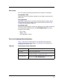
Accessing SPECTRUM Views
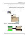
To access the Icon Subviews menu as shown in Figure 1-2 and Figure 1-3, do
the following:
1. Highlight the icon or label.
2. From the View menu, select Icon Subviews, or click and hold the
applicable mouse button (middle or right) over the icon or label. Refer to
the Icons documentation for information on configuring your mouse.
Figure 1-2.
Accessing Icon Subviews Menus from the Device Icon
Model Name
Hub_SynSer3xxx
View
Ctrl+b
Go Back
Go Up
Icon Subviews
View Path
New View
Bookmarks
View History
Current View Info...
Notes...
Jump by name...
Zoom
Map Hierarchy
Figure 1-3.
Device
DevTop
Accessing Icon Subviews Menus from Labels
ON
t1
ISO88025
0:0:1D:52:CF:F2
0
9030920 E6
Close
Ctrl+c
Navigate
Alarms
Performance
Notes...
Utilities
Zoom
Close
Ctrl + c
Navigate
Alarms
Performance
Notes...
Utilities
Configuration
Model Information
Common
Device-Specific
Introduction
1-7
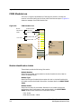
Roadmap of SPECTRUM Views
Roadmap of SPECTRUM Views
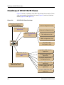
Figure 1-4 shows a “roadmap” of the SPECTRUM views for this device. These
views are accessible from double-click zones (Figure 1-1) and Icon Subviews
menus (Figure 1-2 and Figure 1-3).
Figure 1-4.
SPECTRUM Views Roadmap
Performance view; refer to the
SPECTRUMViews.
Device Configuration view
Device view; see Chapter 2,
Device View.
Ethernet Configuration view
Configuration view; see
Chapter 3, Configuration
Views.
TR Configuration view
FDDI Configuration view
Model Name
Ethernet Bridge
Configuration view
Hub_SynSer3xxx
SynOptics 3000 Common
Application
Application view; see
Chapter 5, Application
View.
SynOptics 3000 FDDI
Application
SynOptics 3000 Ethernet
Bridge Application
DevTop view; refer to the
SynOptics 3000 Token Ring
Application
SPECTRUM Views.
SynOptics 3000 FDDI SMT
Application
SynOptics 3000 FDDI MAC
Application
Introduction
1-8
SynOptics Series 3000 Hub
Management Module Guide
Chapter 2
Device View
What is in this Chapter
This chapter describes the following Device views available for the SynOptics
3000 Series Hubs management module:
• Logical Device View
• Physical Device View
• Bridge Device View
See Chapter 1, Introduction, for information on Accessing SPECTRUM Views.
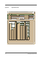
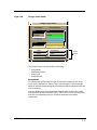
Logical Device View
This view displays a logical representation of the modules installed in the
hub. The logical module representation provides information about the
individual modules and its ports. Figure 2-1 show examples of a Logical
Device view with module for Ethernet, Token Ring, and FDDI hubs. If the
configuration changes (for example, a module is pulled or added to the hub),
you see the corresponding change within this Device view after the next
SPECTRUM polling cycle for the hub.
NOTE
The SynOptics 332xS Ethernet Local Bridge will not have a Logical Device
View. The hub representation is not a true reflection of a Logical Device in
that the modules are of different technologies (Ethernet, FDDI, etc.). In your
view the hub will show only those modules for a technology-specific hub.
9032209 E1
2-1
Logical Device View
Figure 2-1.
Logical Device View
Example of type HubSyn3xxx of Landscape daedalus:Primary
*
File
View
Help?
Net Addr
Model Name
Sys Up Time
Contact
Manufacturer
Description
Device Type
Location
Prime-App
1
2
3
33145
3308
3301
ON
ON
ON
1
NLNK
4
5
5
3910S
Serial Number
6
7
8
3902A
3905
1
NLNK
1
ON
1 Enable
1 Enable
1 Enable
2
NLNK
2
ON
2 Enable
2 Enable
2 Enable
3
NLNK
3
ON
3 Enable
3 Enable
4
ON
4
ON
4 Enable
4 Enable
5
NLNK
5
ON
6
NLNK
6
ON
7
NLNK
7
ON
8
NLNK
8
ON
9
NLNK
10 NLNK
9
10
10
ON
11
11
ON
33145
3301
R1 16M
R1 16M
1
Ring
1
BYP
2
Ring
2
BYP
Sta
ON
3
Sta
ON
4
Sta
ON
5
11 NLNK
12 NLNK
Sta
ON
Sta
ON
6
Sta
BYP
7
Sta
BYP
8
Sta
BYP
9
Sta
BYP
10
Sta
BYP
11
Sta
BYP
12
Sta
BYP
2-2
Token Ring SmartSwitch Module
Management Module Guide
Logical Device View
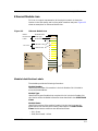
Ethernet Module Icon
This icon is a logical representation of the physical module. It shows the
location in the hub chassis and its front panel interfaces and ports. Figure 2-2
shows an example of an Ethernet Module icon.
Figure 2-2.
Ethernet Module Icon
Module
Module Number
Identification
Labels
Model Type
2
3308
ON
Module Status
1
NLNK
Port Number Label
2
NLNK
Port Status Label
3
NLNK
4
ON
5
NLNK
6
NLNK
7
NLNK
8
NLNK
Port Icons
Close
Navigate
Alarms
Performance
Notes...
Utilities
Port Notes
Port Performance
Alt+F4
9
NLNK
10
NLNK
11
NLNK
12
NLNK
Close
Alt+F4
Navigate
Alarms
Performance
Notes...
Utilities
Module Notes
Module Port Table
Module Configuration
Module Performance
Module Identification Labels
These labels provide the following information:
Module Number
Identifies the number of the module in the hub. Double-click this label to
access the Module Notes.
Module Type
Identifies the type of module that occupies this slot in the hub. Double-click
this label to access the Model Information view described in the SPECTRUM
Views.
Module Status
Identifies the status of the module. Double-click this label to access the
performance view. Performance views are described in the SPECTRUM
Views. Module status conditions are defined as follows:
• ON - Green
• PAR (Partitioned) - Yellow
9032209 E1
2-3
Logical Device View
Module Icon Subviews Menu Selections
Table 2-1 lists each of the device-specific Icon Subviews menu selections
available for this device. See Chapter 1, Introduction, for information on
Accessing SPECTRUM Views.
Table 2-1.
Module Icon Subviews Menu
Menu Selection
Description
Module Notes
Opens the Module Notes view which allows you to keep
notes specific to this module.
Module Port Table
Opens the Port Table view.
Module Configuration
Opens the Ethernet Configuration view described in
Chapter 3, Configuration Views.
Module Performance
Opens the Performance view described in the
SPECTRUM Views.
Port Icon
Port icons display the following information for each port on the device:
Port Type Label
Identifies which port this icon represents. Double-click this label to access the
Port Notes view.
Port Status Label
Displays the status of the port. Double-click this label to open the Port
Performance view. Port status conditions are defined as follows:
• NLNK (No Link) - Yellow
• ON - Green
• OFF - Blue
Port Icon Subviews Menu Selections
Table 2-2 lists each of the port-specific Icon Subviews menu selections
available for this device. See Chapter 1, Introduction, for information on
Accessing SPECTRUM Views.
2-4
Token Ring SmartSwitch Module
Management Module Guide
Logical Device View
Table 2-2.
Ethernet Port Menu Selections
Menu Selection
Description
Port Notes
Opens the Port Notes view.
Port Performance
Opens the Port Performance view described in
the SPECTRUM Views.
Token Ring Module Icon
This icon is a logical representation of the physical module. It shows the
location in the hub chassis and its front panel interfaces and ports. Figure 2-3
shows an example of a Token Ring Module icon.
Figure 2-3.
Token Ring Module Icon
Module Number
Module
Module Status
Identification
Labels
Model Type
Ring Number
Module Speed
3
ON
3505
R1
1
16M
Sta
ON
Port Icons
Port Number Label
Port Type Label
Port Status Label
2
Sta
ON
3
Sta
ON
Close
Navigate
Alarms
Performance
Notes...
Utilities
Port Notes
Port Performance
Alt+F4
Close
Alt+F4
Navigate
Alarms
Performance
Notes...
Utilities
Module Notes
Module Port Table
Module Configuration
Module Performance
9032209 E1
2-5
Logical Device View
Module Identification Labels
These labels provide the following information:
Module Number
Identifies the slot number of the module in the hub. Double-click this label to
access the Module Notes.
Model Type
Identifies the model type for this device.
Module Status
Identifies the operating status of the module. Double-click this label to access
the Module Performance view described in the SPECTRUM Views.
Ring Number
Identifies which ring this module is on.
Module Speed
Identifies the transmission speed setting of the module.
Module Icon Subviews Menu Selections
Table 2-3 lists each of the device-specific Icon Subviews menu selections
available for this device. See Chapter 1, Introduction, for information on
Accessing SPECTRUM Views.
Table 2-3.
Module Icon Subviews Menu
Menu Selection
2-6
Description
Module Notes
Opens the Module Notes view which allows you to keep
notes specific to this module.
Module Port Table
Opens the Port Table view.
Module Token Ring
Configuration
Opens the SynOptics Module Token Ring Module
Configuration view described in Chapter 3, Configuration
Views.
Module Configuration
Opens the SynOptics Module Configuration view
described in Chapter 3, Configuration Views.
Module Performance
Opens the Performance view described in the
SPECTRUM Views.
Token Ring SmartSwitch Module
Management Module Guide
Logical Device View
Port Icons
Port icons display the following information for each port on the device:
Port Number Label
Identifies the port on this device. Double-click this label to access the Port
Notes view.
Port Type Label
Identifies the type of port on this device. Possible types are Station (Sta) or
Ring In/Ring Out (Ring). Double-click this label to access the Token Ring
Configuration described on Page 3-11.
Port Status Label
Displays the operating status of this port. Double-click this label to access the
Port Performance view described in the SPECTRUM Views. Port status
conditions are as follows:
• ON - Green
• WRAP - Red
• BYP (Bypassed) - Yellow
Port Icon Subviews Menu Selections
Table 2-4 lists each of the port-specific Icon Subviews menu selections
available for this device. See Chapter 1, Introduction, for information on
Accessing SPECTRUM Views.
Table 2-4.
Token Ring Port Menu Selections
Menu Selection
Description
Port Notes
Opens the Port Notes View.
Port Configuration
Opens the SynOptics Token Ring Port Configuration view
described in Chapter 3, Configuration Views.
Port Performance
Opens the SynOptics Token Ring Port Performance view
described in the SPECTRUM Views .
9032209 E1
2-7
Logical Device View
FDDI Module Icon
This icon is a logical representation of the physical module. It shows the
location in the hub chassis and its front panel interfaces and ports. Figure 2-4
shows an example of an FDDI Module icon.
Figure 2-4.
FDDI Module Icon
Module
Module Number
Identification
Labels
Model Type
2
3905
ON
Module Status
1
NLNK
Port Number Label
2
NLNK
Port Status Label
3
NLNK
4
ON
5
NLNK
6
NLNK
7
NLNK
8
NLNK
Port Icons
Close
Navigate
Alarms
Performance
Notes...
Utilities
Port Notes
Port Performance
Alt+F4
9
NLNK
10
NLNK
11
NLNK
12
NLNK
Close
Alt+F4
Navigate
Alarms
Performance
Notes...
Utilities
Module Notes
Module Port Table
Module Configuration
Module Identification Labels
These labels provide the following information:
Module Number
Identifies the number of the module in the hub. Double-click this label to
access the Module Notes.
Module Type
Identifies the type of module that occupies this slot in the hub. Double-click
this label to access the Model Information view described in the SPECTRUM
Views.
Module Status
Identifies the status of the module. Double-click this label to access the
performance view. Performance views are described in the SPECTRUM
Views. Module status conditions are defined as follows:
• ON - Green
• PAR (Partitioned) - Yellow
2-8
Token Ring SmartSwitch Module
Management Module Guide
Logical Device View
Module Icon Subviews Menu Selections
Table 2-5 lists each of the device-specific Icon Subviews menu selections
available for this device. See Chapter 1, Introduction, for information on
Accessing SPECTRUM Views.
Table 2-5.
Module Icon Subviews Menu
Menu Selection
Description
Module Notes
Opens the Module Notes view which allows you to keep
notes specific to this module.
Module Port Table
Opens the Port Table view.
Module Configuration
Opens the Ethernet Configuration view described in
Chapter 3, Configuration Views.
Module Performance
Opens the Performance view described in the
SPECTRUM Views.
Port Icon
Port icons display the following information for each port on the device:
Port Type Label
Identifies which port this icon represents. Double-click this label to access the
Port Notes view.
Port Status Label
Displays the status of the port. Double-click this label to open the Port
Performance view. Port status conditions are defined as follows:
• NLNK (No Link) - Yellow
• ON - Green
• OFF - Blue
9032209 E1
2-9
Physical Device View
Port Icon Subviews Menu Selections
Table 2-6 lists each of the port-specific Icon Subviews menu selections
available for this device. See Chapter 1, Introduction, for information on
Accessing SPECTRUM Views.
Table 2-6.
FDDI Port Menu Selections
Menu Selection
Description
Port Notes
Opens the Port Notes view.
Port Performance
Opens the Port Performance view described in
the SPECTRUM Views.
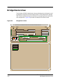
Physical Device View
The SynOptics hub Physical Device view shows a physical representation of
the hub and the modules installed within it. Figure 2-5 show an example a
Physical Device view.
NOTE
The SynOptics 332xS Ethernet Local Bridge will not have a Physical Device
view.
The Physical Device view allows you to access the same Icon Subviews menus
for modules installed in the SynOptics hub as the Logical view. To access the
Icon Subviews:
1. Click on a module icon within the view to highlight it.
2. From the View menu, select Icon Subviews.
Port views cannot be accessed from this view.
NOTE
2-10
Token Ring SmartSwitch Module
Management Module Guide
Physical Device View
Figure 2-5.
Physical Device View
Example of type HubSyn3xxx of Landscape daedalus:Primary
*
File
Model Name
View
Help?
Net Addr
Sys Up Time
Contact
Manufacturer
Description
Location
Device Type
Prime-App
LattisNet
3508
106RGe-7
Serial Number
LattisNet
3508
106RGe-7
Port
LattisNet
3508
106RGe-7
Port
Port
Plot
Plot
Plot
Mutt J eff
Mutt Jeff
Mutt Jeff
Mutt J eff
Mutt Jeff
Mutt Jeff
Mutt Jeff
Mutt Jeff
Mutt Jeff
What
one
What
two
one
on e
two
on e
two
What
two
one
one
two
one
two
one
two
one
two
What
What
two
What
whatisit
wh atisit
whatisit
Telco Port
Telco Port
Telco Por t
Telco
Telco
Telco
Reset
Reset
Reset
9032209 E1
2-11
Bridge Device View
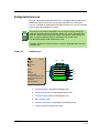
Bridge Device View
The SynOptics 332xS Bridge Device view provides dynamic configuration and
performance information for the bridge interface. If the configuration changes,
SPECTRUM modifies the Device view after the next polling cycle to reflect the
new configuration. Figure 2-6 provides an example of the Device view.
Figure 2-6.
Bridge Device View
Example of type BdgSyn332xS of Landscape daedalus:Primary
*
File
View
Help?
Net Addr
Model Name
Contact
Sys Up Time
Manufacturer
Description
Device Type
Location
Prime-App
Serial Number
Model Name
Find
BdgSyn332xS
Physical
Network Information
ADDRESS
Interface Description
ON
1
Ethernet
0:0:1D:17:2F:3C
IP Address
0
2-12
Token Ring SmartSwitch Module
Management Module Guide
Bridge Device View
Bridge Interface Icon
This icon represents the Bridge interface for the BdgSyn332xS model type. It
identify the type of interface or port and provide statistical information.
Figure 2-7 provides an example of the Bridge Interface icon, its Icon Subviews
menu, and its labels/double-click zones.
NOTES
The callouts (a through f) displayed in the illustration below identify the
label and the view to which it provides double-click access. Example: MAC
Address Label/CSIdtrInterface Port Model Information View displays the
MAC or physical address and provides double-click access to the
CSIdtrInterface Port Model Information View.
The menu displayed in the illustration is the Icon Subviews menu for that
Interface icon.
Figure 2-7.
Interface Icon
Close
Alt+F4
Navigate
Alarms
Performance
Notes...
Utilities
DevTop
Detail
IF Status
IF Configuration
IF Address Translation Table
Network Information Panel
Thresholds
Model Information
(a)
(b)
1
ON
Ethernet
(c)
0:0:1D:17:2F:3C
(d)
IP Address
(e)
0
(f)
a. Interface Number Label/Device Topology View
b. Administrative Status Label/Interface Status View
c.
Port Type Label/Interface Configuration View
d. MAC Address Label
e.
Network Information Label/Network Information Panel
f.
Gauge Label/IfPort Performance View
9032209 E1
2-13
Bridge Device View
Interface Number Label
This label displays the number identifying the interface. Double-click on this
label to access the Bridge Device Topology (DevTop) view described in the
SPECTRUM Views.
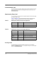
Administrative Status Label
This label displays the status of this interface. Double-click this label to open
the Interface Status View.
Table 2-7 and Table 2-8 list the possible states relative to the application
selected. The default application for this view is Physical (MIB-II).
Table 2-7.
Administrative Status for the Physical Application
Color
Table 2-8.
Status
Description
Green
ON
Port is operational.
Blue
OFF
Port is off.
Yellow
TST
Port is in the test mode.
Administrative Status for the Bridging Application
Color
Status
Description
Green
FWD
Bridge port is forwarding.
Blue
DIS
Port is disabled.
Magenta
LST
Bridge is in the listening mode.
Magenta
LRN
Bridge is in the learning mode
Orange
BLK
Bridge port is in the blocking mode.
Red
BRK
Bridge port is broken.
Blue
???
Status is unknown.
Port Type Label
This label displays the type of hardware interface or port; for example,
Reg1822, Prot10MB, PPP, T1, etc. For a complete listing of all interface types,
refer to the SPECTRUM Views.
2-14
Token Ring SmartSwitch Module
Management Module Guide
Bridge Device View
MAC Address Label
This label displays the MAC or physical address of the interface.
Network Information Label
This label displays user-selectable network information (Address, Name, or
Mask). The default is Address.
To change this label’s display, use the Interface Options Panel or do the
following:
1. Double-click the label to open the Network Information Panel.
2. Click the network information entry you wish to display.
3. Click OK.
Gauge Label
This label displays the performance statistic determined by the Gauge Control
Panel for this interface. Double-click this label to open the Performance view
described in the SPECTRUM Views.
9032209 E1
2-15
Bridge Device View
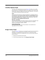
Interface Options Panel
This area of the Interface Device view (see Figure 2-8) allows you to modify
the presentation of a highlighted Interface icon. Double-click a non-text area
of this panel to open the Gauge Control Panel, described below. The Interface
Options panel provides the following information:
Filter
This menu button allows you to select the application to be displayed by the
Interface icons. You can leave the default Physical or select Bridging. You can
also select other applications such as IP routing if the SPECTRUM Routing
Services Management Module is loaded. For more information, refer to the
Routing Services Management Module Guide.
Network Information
This menu button allows you to select the type of information displayed in the
Network Information label of the highlighted Interface icon. Possible
selections are ADDRESS, NAME, or MASK.
Interface Description
This field provides a description of the interface. If no Interface icon is
highlighted, this field is empty.
Gauge Control Panel
This panel (Figure 2-8) allows you to change the type of statistical information
displayed on the Gauge label of the Interface icon. To access the Gauge
Control Panel, double-click the background of the Interface Options panel or
do the following:
1. Highlight the Interface Options panel.
2. From the Icon Subviews menu, select Gauge Control Panel.
2-16
Token Ring SmartSwitch Module
Management Module Guide
Bridge Device View
Figure 2-8.
Gauge Control Panel
Gauge Control Panel
Gauge Mode
Rates
Selected Attribute
Load
Totals
Load In
Percentages
Load Out
Packet Rate
Gauge Type
In Packet Rate
Out Packet Rate
Numeric
% Discard
Linear
% Filtered
Apply
Keep Settings
Reset
Close
Gauge
Buttons
Default
The Gauge Control Panel provides the following:
•
•
•
•
Gauge Mode
Selected Attribute
Gauge Type
Gauge Buttons
Gauge Mode
This area allows you to select the type of information shown on the Gauge
Label of the Interface icon: Rates, Totals, or Percentages. The Percentages
selection displays the percentage of the selected interface compared to the rest
of the interfaces.
The color displayed on the Gauge Label depends upon the particular mode
and statistical attribute selected. Table 2-9 and Table 2-10 list the attributes
and their corresponding colors for the Rates mode and Totals mode,
respectively.
9032209 E1
2-17
Bridge Device View
Table 2-9.
Rate Gauge Mode: Attributes and Corresponding Color
Selected Attribute
Table 2-10.
Color
Load
Green
Load In
Green
Load Out
Green
Packet Rate
Blue
In Packet Rate
Blue
Out Packet Rate
Blue
% Discard
Tan
% Filtered
Gray
% Forwarded
Violet
% Host Bound
Yellow
% Error
Orange
% Transmitted
White
Totals Gauge Mode: Attributes and Corresponding Color
Selected Attribute
Color
Errors
Orange
In Packets
Blue
Out Packets
Blue
In Octets
Green
Out Octets
Green
Discards
Tan
Forwarded
Purple
Host Bound
Yellow
Transmitted
White
Filtered
Gray
Selected Attribute
This area allows you to select the statistical attribute displayed on the
Interface icon’s Gauge label. The label changes color to reflect the attribute
selected.
Gauge Type
This option allows you to select either a numeric or linear display on the
Gauge label.
2-18
Token Ring SmartSwitch Module
Management Module Guide
Bridge Device View
Gauge Buttons
The following describes the Gauge buttons:
Apply
Applies the current settings to the Gauge label temporarily but does not save
the settings.
Keep Settings
Saves the current settings while using SpectroGRAPH. Settings return to
default when you restart SpectroGRAPH.
Reset
Returns the settings to the previously saved values.
Close
Closes the Gauge Control Panel.
Default
Returns the settings to the SPECTRUM default.
9032209 E1
2-19
Bridge Device View
2-20
Token Ring SmartSwitch Module
Management Module Guide
Chapter 3
Configuration Views
What is in this Chapter
This chapter describes the following Configuration menu selections and views
available for the SynOptics Model 3000 Series Management Module:
• NMM Nodes
- SynOptics Token Ring Show Nodes Table View
- SynOptics Token Ring Find Nodes Table View
• Ethernet Configuration
-
SynOptics Ethernet
SynOptics Ethernet
SynOptics Ethernet
SynOptics Ethernet
SynOptics Ethernet
Frames and Errors View
Frame Sizes and Protocols View
NMM Table View
Host Table View
Threshold Table View
• Token Ring Configuration
-
SynOptics Token Ring Station Table View
SynOptics Token Ring Total Errors Table View
SynOptics Token Ring Station Isolating Errors View
SynOptics Token Ring Station Non-Isolating Errors View
SynOptics Token Ring NMM Topology Table View
SynOptics Token Ring NMM Configuration View
9030920 E6
3-1
NMM Nodes
• FDDI Configuration
-
SynOptics FDDI NMM Ring Status View
SynOptics FDDI NMM Station Worst Errors View
SynOptics FDDI NMM SRF Event Counters View
SynOptics FDDI NMM SRF Condition View
SynOptics FDDI NMM Ring Topology View
SynOptics Physical Topology Trunk View
SynOptics Physical Topology Node View
SynOptics NMM Optical Bypass Switch View
• Device Configuration
-
SynOptics Configuration View
SynOptics Agent Download View
SynOptics Agent Protocol Configuration View
SynOptics Agent Configuration View
SynOptics Agent Hardware View
SynOptics IP Trap Receiver View
SynOptics IPX Trap Receiver View
• SynOptics Chassis Configuration View
• SynOptics Ethernet Local Bridge Configuration View
See Chapter 1, Introduction, for information on Accessing SPECTRUM Views.
NMM Nodes
This menu selection from the device icon provides access to the following
NMM nodes views. To access these views, select NMM Nodes from the Icon
Subviews menu for the device and then one of the following menu/view
selections:
• Show Nodes/SynOptics Token Ring Show Nodes Table View
• Find Nodes/SynOptics Token Ring Find Nodes Table View
SynOptics Token Ring Show Nodes Table View
This table contains a list of all of the active nodes that are currently connected
to the ring through this concentrator. To access this view, select Show Nodes
from the NMM Nodes menu for the device icon.
Module
The board number.
Configuration Views
3-2
SynOptics Series 3000 Hub
Management Module Guide
NMM Nodes
SynOptics Token Ring Find Nodes Table View
Port
The port number.
Address
The physical MAC address.
Vendor
The vendor of the device connected to that port. This is determined from the
MAC address.
SynOptics Token Ring Find Nodes Table View
This table contains a list of all of the active nodes that are currently connected
to the ring through this concentrator. The Show Nodes and Find Nodes tables
differ in their indexing. The Find Nodes table identifies a module and port for a
given NMM’s interface and a given MAC address.To access this view, select
Find Nodes from the NMM Nodes menu for the device icon.
Module
The module number.
Port
The port number.
Address
The physical (MAC) address.
Vendor
The vendor of the device connected to that port. This is determined from the
MAC address.
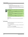
NOTE
9030920 E6
If you get a message that the view is not available at this time, you may have
to cause the model to be reconfigured by selecting Reconfigure from the
Application View Edit menu. If you are installing over an existing Ethernet
or Token Ring version, you must reconfigure to open the Chassis
Configuration View.
Configuration Views
3-3
Ethernet Configuration
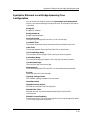
Ethernet Configuration
This menu selection provides access to the following views. These views
contain network configuration information for the SynOptics Model 3000
Series Ethernet hub device. To access these views, select Ethernet
Configuration from the Icon Subviews menu for the device and then one of
the following menu/view selections.
• Frames and Errors/SynOptics Ethernet Frame Sizes and Protocols View
• Frame Sizes and Protocols/SynOptics Ethernet Frame Sizes and
Protocols View
• NMM Table/SynOptics Ethernet NMM Table View
• Host Table/SynOptics Ethernet Host Table View
• Threshold/SynOptics Ethernet Threshold Table View
SynOptics Ethernet Frames and Errors View
This view displays pie chart statistics for frames and error breakdowns. For
information on pie charts refer to the SPECTRUM Views. This view also
displays the following information:
Board
A unique value for each board.
Port
The media connection type for this port.
Link
Whether the port is receiving link status.
Intercon
Whether the port is connected to a host or to an interconnect.
Part Status
The operational status of the port. Possible values are: enabled, partition,
autopartition, timedpartition, latSecPartition.
Good Frames
The number of good frames.
Alignment
A count of frames received by the concentrator that are not an integral
number of octets in length and do not pass the FCS check.
FCS
A count of frames received by the concentrator that are an integral number of
octets in length that do not pass the FCS check.
Configuration Views
3-4
SynOptics Series 3000 Hub
Management Module Guide
Ethernet Configuration
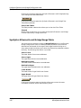
SynOptics Ethernet Frame Sizes and Protocols View
Runts
A count of frames received by the concentrator that are less than the
minimum permitted frame size and have a good FCS.
Giants
The number of giants.
OOW
The number of OOWs.
Collisions
A total count of the late collisions.
SynOptics Ethernet Frame Sizes and Protocols View
This view displays pie chart statistics for frames and protocols. For
information on pie charts refer to the SPECTRUM Views.
SynOptics Ethernet NMM Table View
The SynOptics Ethernet NMM Table view provides a list of all the active MAC
addresses that are currently connected to a specified segment identified by an
interface on an NMM, and are directly connected to a host port on the chassis
or are a MAC on a board in the chassis. The NMM Table view provides the
following information:
Module
The module number.
Port
The port number.
Address
The physical (MAC) address.
Vendor
The vendor of the device connected to that port. This is determined from the
MAC address.
SynOptics Ethernet Host Table View
This view displays the following information:
Slot
The board index that the host is connected through.
9030920 E6
Configuration Views
3-5
Ethernet Configuration
SynOptics Ethernet Threshold Table View
Port
The port index that the host is connected through.
Type
The type of address that is stored in the Net Addr for this device.
Net Addr
The network address (in network order) of the MAC/Network address pair.
MAC Address
The network address (in canonical order) of the MAC/Network address pair.
Vendor
The vendor of the device connected to that port. This is determined from the
MAC address.
Learn
The method that was used to discover the MAC/Network address pair.
Possible methods are:
•
•
•
•
•
Other - unknown method
arpRequest - ARP request packets
arpResponse - ARP response packets
ripRequest - RIP request packets
ripResponse - RIP response packets
Time Stamp
The value of sysUpTime when the MAC/Network address pair was last
observed on the segment.
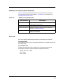
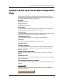
SynOptics Ethernet Threshold Table View
The Thresholds Table View provides the following information:
Index
The index into the Threshold table.
Object
Specifies the part of the concetrator the threshold applies. Possible values are:
•
•
•
•
Other- Unknown threshold error.
Port- Applies to a specific port in the concentrator.
Ring- Applies to the ring to which the NMM is connected.
Station- Applies to a specific station identified by the MAC address.
All values are read-write with the exception of “other” which is read-only.
NOTE
Configuration Views
3-6
SynOptics Series 3000 Hub
Management Module Guide
Ethernet Configuration
Slot
Displays the slot number of the port being monitored by the threshold.
Port
Displays the port number of the port being monitored by the threshold.
Type
Determines which type of threshold applies to this entry. The possible values
are:
• Applicable to the Ring and Station thresholds only:
-
lineError- Count of line errors.
burstError- Count of burst errors.
arcFciError- Count of ARI FCI errors.
recvCongestionErr- Count of recieve congestion errors.
frameCopyError- Count of frame copy errors.
tokenError- Count of token errors.
lostFrame- Count of lost frame errors.
beaconing- Count of beacon frames.
• Applicable to Ring thresholds only:
- goodOctets- Count of good bytes.
- goodFrames- Count of good frames.
- utilization- Total byte count of all good and bad frames seen per
second, divided by the ring speed in bytes per second.
• Applicable to Station thresholds only:
- stationInserts- Station inserted into the NMM’s ring.
- stationDeinserts- Station deinserted frim the NMM’s ring.
• Applicable to the Port thresholds only:
- portPhantomStatus- Phantom signal has changed from off to on or
visa-versa.
NOTE
9030920 E6
The value of Other can only be read, and it indicates the entry has an invalid
or unknown threshold type.
Configuration Views
3-7
Ethernet Configuration
Condition
Conditions that set off the threshold. The possible values are:
• other- None of the following.
• crossValue- The actual value crosses the set value (i.e., either from lower
to higher or higher to lower).
• overValue- The actual value/sec is greater than the set value/sec.
• overRate- The rate of the Actual Value/second is greater than the Set
Value/second.
• phantomOn- The phantom signal of the port has changed to On.
• phantomOff- The phantom signal of the port has changed to Off.
The values threshold Condition can have is actually dependent on the value of
the threshold Type. Table 3-1 shows the valid combinations between the two
objects.
Table 3-1.
Threshold Condition
Threshold Type
Allowed Values for Threshold Condition
lineError (2)
Possible values are 2,3, or 4.
burstError (3)
Possible values are 2,3, or 4.
arcFciError (4)
Possible values are 2,3, or 4.
recvCongestionErr (5)
Possible values are 2,3, or 4.
frameCopyError (6)
Possible values are 2,3, or 4.
tokenError
Possible values are 2,3, or 4.
lostFrame (8)
Possible values are 2,3, or 4.
beaconing (9)
Possible values are 2,3, or 4.
goodOctets (10)
Possible values are 2,3, or 4.
goodFrames (11)
Possible values are 2,3, or 4.
utilization (12)
Possible values are 2 or 3.
stationInserts (13)
Any value is possible.
stationDeinserts (14)
Any value is possible.
portPhantomStatus (15) Possible values are 5 or 6.
When the condition specified is crossValue or overValue, the Actual value is
accumulated from the beginning of the duration window and is checked every
five seconds.
When the condition specified is overRate and the duration is less than or
equal to five seconds, the Actual value is based on the data accumulated
during the five second sampling period.
Configuration Views
3-8
SynOptics Series 3000 Hub
Management Module Guide
Ethernet Configuration
When the condition specified is overRate and the duration is greater than
five seconds, the Actual value is based on the data accumulated during the
entire duration window.
Set Value
Threshold setting value. This value must be set to a number greater than zero
for the following types of thresholds:
•
•
•
•
•
•
•
•
•
•
•
lineError
burstError
arcFciError
recvCongestionErr
frameCopyError
tokenError
lostFrame
beaconing
goodOctets
goodFrames
utilization
Actual Value
Current value of the threshold counter. This value is set to zero at the
beginning of each duration window.
NOTES
If the type of threshold is station, and the station is not on the same ring as
the NMM, this value will remain at zero, which will prevent the threshold
condition from ever being met.
This object is not used for evaluating the threshold condition, and will
remain at zero if the type of threshold is port.
Action
Determines which action is to take place if the threshold condition occurs. The
possible values that can be read and written are listed below for each
threshold type:
• Port, Ring, and Station thresholds:
- noAction- Take no action.
- sendTrap- Send a trap.
• Port thresholds only:
- partSlotPort- Partition the port identified by the threshold Slot entry
and the threshold Port entry.
- trapPartSlotPort- Send a trap and partition the port identified by the
threshold Slot entry and the threshold Port entry.
9030920 E6
Configuration Views
3-9
Ethernet Configuration
• Station thresholds only:
- removeMAC- Send Remove MAC frame to station identified by MAC
address contained in the threshold MAC Address.
- trapRemoveMAC- Send a trap and then send a Remove MAC frame to
the station identified by the MAC address contained in the threshold
MAC Address.
NOTE
The timing and frequency of the action taken when the threshold condition is
met is dependent upon the threshold Condition value and the length of the
duration window.
• If the threshold Condition is crossValue, the action will be taken only
once during the durationwindow of the sampling period in which the
condition is first met.
• If the threshold Condition is overValue, the action will be taken at each
sampling period in which the condition is met until the end of the
duration window.
• If the threshold Condition is overRate, the action will be taken only
once at the end of the duration window if the condition is met.
Exceed Count
Counter for how many times the settled threshold has reached its setting
value.
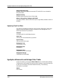
Add Threshold
The Add Threshold buttons allow you to add or change information to the
ring, station, or port as follows:
1. Click the applicable button.
2. Within the view that opens, make any changes to, or add new thresholds
as needed.
3. From the File Menu, Save Changes.
The Ring and Station views display the following additional information:
Configuration Views
3-10
SynOptics Series 3000 Hub
Management Module Guide
Token Ring Configuration
Token Ring Configuration
This menu selection provides access to the following views. These views
contain network configuration information for the SynOptics Model 3000
Series Token Ring hub device. To access these views, select Token Ring
Configuration from the Icon Subviews menu for the device and then one of
the following menu/view selections.
• Station Table/SynOptics Token Ring Station Table View
• Station Total Errors/SynOptics Token Ring Total Errors Table View
• Station Non-Isolating Errors/SynOptics Token Ring Station NonIsolating Errors View
• NMM Topology Table/SynOptics Token Ring NMM Topology Table View
• TR NMM Configuration/SynOptics Token Ring NMM Configuration
View
• Threshold/SynOptics Ethernet Threshold Table View
SynOptics Token Ring Station Table View
This view displays pie chart statistics for isolating and non-isolating. For
information on pie charts refer to the SPECTRUM Views. This view also
displays the following information:
MAC Address
The MAC address of the station.
Slot
The board index that the host is connected through.
Port
The number identifying the port.
Beacon Status
The beaconing status of the station.
Functional Addr
The functional address used by the station (this value may or may not be the
station’s MAC address).
Classes
Specifies the functional classes allowed to be active in the station.
Priority
The maximum priority the station is allowed to use.
Group Address
The group address of the station.
Station ID
An octet string used to uniquely identify the station.
9030920 E6
Configuration Views
3-11
Token Ring Configuration
SynOptics Token Ring Total Errors Table View
SynOptics Token Ring Total Errors Table View
This view displays pie chart statistics for isolating and non-isolating errors.
For information on pie charts refer to the SPECTRUM Views. This view also
displays the following information:
MAC Address
The MAC address of the station.
Line
The number of line errors.
Burst
The number of burst errors.
Ar
The number of ARI FCI errors.
Abort
The number of abort delimiter errors.
Internal
The number of internal errors.
Lost Frm
The number of lost frames.
Congestion
The number of receive congestion errors.
Frm Copy
The number of frame copy errors.
Token
The number of token errors.
Frequency
The number of frequency errors.
SynOptics Token Ring Station Isolating Errors View
This view displays pie chart statistics for isolating and non-isolating errors.
For information on pie charts refer to the SPECTRUM Views. This view also
displays the following information:
MAC Address
The MAC address of the station.
Slot
The board index that the host is connected through.
Configuration Views
3-12
SynOptics Series 3000 Hub
Management Module Guide
Token Ring Configuration
SynOptics Token Ring Station Non-Isolating Errors View
Port
The number identifying the port.
Line
The number of line errors.
Burst
The number of burst errors.
Ar
The number of ARI FCI errors.
Abort
The number of abort delimiter errors.
Internal
The number of internal errors.
SynOptics Token Ring Station Non-Isolating Errors View
This view displays pie chart statistics for isolating and non-isolating errors.
For information on pie charts refer to the SPECTRUM Views. This view also
displays the following information:
MAC Address
The MAC address of the station.
Slot
The board index that the host is connected through.
Port
The number identifying the port.
Lost Frm
The number of lost frames.
Congestion
The number of receive congestion errors.
Frm Copy
The number of frame copy errors.
Token
The number of token errors.
Frequency
The number of frequency errors.
9030920 E6
Configuration Views
3-13
Token Ring Configuration
SynOptics Token Ring NMM Topology Table View
SynOptics Token Ring NMM Topology Table View
This view provides a list of all the active MAC addresses that are currently
connected to a specified segment identified by an interface on an NMM, and
are directly connected to a host port on the chassis or are a MAC on a board in
the chassis. The NMM Table view provides the following information:
Module
The module number.
Address
The physical (MAC) address.
Vendor
The vendor of the device connected to that port. This is determined from the
MAC address.
SynOptics Token Ring NMM Configuration View
This view provides the following configuration information for this device:
Module
The number of the slot containing the module.
Network
You may enter the flat network number that this NMM is part of.
Segment
The segment number (in the concept of Token Ring the segment means the
ring) that this NMM is connected to.
Ring Status
The status of the ring.
Ring
The identifying number of the ring.
Ring Speed
The speed at which the hub is configured to operate.
FPU Revision
The revision number of the front end processing unit.
FPU Status
The status of the front end processing unit.
DRAM Size
The highest address of DRAM in the NMM memory map.
EEPROM Size
The size of the EEPROM in the NMM memory map.
Configuration Views
3-14
SynOptics Series 3000 Hub
Management Module Guide
FDDI Configuration
EPROM Size
The size of the EPROM in the NMM memory map.
FDDI Configuration
This menu selection provides access to the following views. These views
contain network configuration information for the SynOptics Model 3000
Series FDDI hub device. To access these views, select FDDI Configuration
from the Icon Subviews menu for the device and then one of the following
menu/view selections.
• NMM Ring Status/SynOptics FDDI NMM Ring Status View
• Station Worst Errors/SynOptics FDDI NMM Station Worst Errors View
• Station SRF Event Counters/SynOptics FDDI NMM SRF Event
Counters View
• Station SRF Condition/SynOptics FDDI NMM SRF Condition View
• NMM Ring Topology/SynOptics FDDI NMM Ring Topology View
• Physical Topology Trunk/SynOptics Physical Topology Trunk View
• Physical Toplolgy Node/SynOptics Physical Topology Node View
• NMM Optical Bypass Switch/SynOptics NMM Optical Bypass
Switch View
SynOptics FDDI NMM Ring Status View
This view provides the following NMM Ring information:
Ring
The index associated with this ring.
Utilization
Ring utilization calculated using the MAC token count and ring latency on
that path.
Wrap State
Indicates if the ring is wrapped.
State Duration
How long the ring has been in the above condition (wrapped or unwrapped).
SynOptics FDDI NMM Station Worst Errors View
This view provides LAN statistics information for the whole LAN. It provides
information about each station’s worst error rates on MACs and ports. It is
indexed by station.
9030920 E6
Configuration Views
3-15
FDDI Configuration
SynOptics FDDI NMM SRF Event Counters View
Worst Error Monitor Operational State
The operational state of the agent worst error monitor process.
Station ID
Station Id of the station with the worst LER errors and Frame errors.
Port w/Worst LER
The port on this station with the worst rate of LER errors.
LER Estimate
The worst LER estimate (long term average link error rate) on the above port.
MAC w/Worst Frame Error Rate
The MAC on this station with the worst rate of frame errors.
MAC Ratio
The worst ratio of frame errors on the above MAC. This value will be between
0 and 65535.
SynOptics FDDI NMM SRF Event Counters View
This view provides LAN statistics informtion fo rhte whole LAN. It provides
informtion about each station’s conditions, events, and worst error rates on
MACs and ports. It is indexed by station.
SRF Monitor Operational State
Indicates the operating status of this station (On or Off).
Station ID
Station ID of the station with the indicated conditions and events.
MAC Neighbor Changes
Number of times this station sees a MAC neighbor change.
MAC Path Changes
Number of times this station sees a path change on one of its MACs.
Port Undesired Connects
The number of times and undesired connection is attempted on this port.
Port Path Changes
The number of times this port changes path.
SynOptics FDDI NMM SRF Condition View
This view provides the following SRF condition information:
SRF Monitor Operational State
Indicates the operating status of this station (On or Off).
Configuration Views
3-16
SynOptics Series 3000 Hub
Management Module Guide
FDDI Configuration
SynOptics FDDI NMM Ring Topology View
Station ID
Station ID of the station with the indicated conditions and events.
Peer Wrap State
Flag indicating if an SMT peer wrap condition has occurred.
MAC Dup Address
Flag indicating if a MAC address condition has been detected.
MAC Frame Err
Flag indicating if a MAC frame error condition has occurred.
MAC Not Copied
Flag indicating if a MAC not copied condition has occurred.
Port LER
Flag indicating if a Port Link Error condition has occurred.
Port EBE
Flag indicating if a port elastic buffer error condition has occurred.
SynOptics FDDI NMM Ring Topology View
This view provides the following NMM Ring Topology information:.
Interface IP
The IP address of the interface. This refers to the interface of the pulling
NMM.
Network #
A unique value for each network. This is the network number where the
pulled NMM resides.
IP Address
IP Address of this NMM entry. This refers to the NMM being pulled.
Chassis Type
The type of the chassis where this NMM resides. The enumerated values of
this object are the same as defined in the common MIM for objects 3Chassis
Type.
MAC Address
The MAC address this entry is for.
Backplane Type
The backplane type of the chassis of this NMM.
Upstream Neighbor
IP address of the upstream neighbor of the station associated with this entry.
If unknown, then this object will contain 0.0.0.0.
9030920 E6
Configuration Views
3-17
FDDI Configuration
SynOptics Physical Topology Trunk View
SynOptics Physical Topology Trunk View
This view provides the following information on all of the stations in the trunk
ring:
Physical Topology Operational State
On/Off
Station ID
Station ID of the node associated with this entry.
IP Address
IP address of the node associated with this entry.
Station State
Used to determine the current state of the node.
Station Type
Station type of this node.
Station Type Mask
Station Type Mask root node on tr unk ring.
Slot
SynOptics slot number where the local NMM A/B/S ports reside.
SynOptics Physical Topology Node View
This view provices the following information for all stations in the trunk ring.
Physical Topology Operational State
On/Off
Station ID
Station ID of the node associated with this entry.
IP Address
IP addressof the node associated with this entry.
Station Type Mask
Station Type Mask for this node.
Num Parents
Contains the number of parent stations of thi s concentrator/station.
Parent Cloud Mask
Bit mask indicating if any of the parents is a cloud.
Num Children
Contains the number of parent stations of this child concentrator or station (a
maximum of 100 ports for FDDI Phase II.)
Configuration Views
3-18
SynOptics Series 3000 Hub
Management Module Guide
FDDI Configuration
SynOptics NMM Optical Bypass Switch View
SynOptics NMM Optical Bypass Switch View
This view displays the following information used to control the Optical
Bypass Switch:
SMT Index
The value of the SMT index associated with this attachment.
Optical Bypass Switch Index
A unique value for each optical bypass switch.
Partition Status
Optical bypass switch partition status.
Partition Timer
Optical Bypass Switch partition timer. When this object is set to default (0),
the concetrator can be removed permanently from the trunk ring by setting
the object s3FDDIAttachPartitionStatus to on/partitioned (1).
Bypass Present
Indicates whether an optical bypass switch is inserted.
9030920 E6
Configuration Views
3-19
Device Configuration
Device Configuration
This menu selection provides access to the following views. These views
contain network configuration information for the SynOptics Model 3000
Series hub device. To access these views, select Device Configuration from
the Icon Subviews menu for the device and then one of the following menu/
view selections.
•
•
•
•
•
•
•
Configuration View/SynOptics Configuration View
Agent Download/SynOptics Agent Download View
Agent Protocol/SynOptics Agent Protocol Configuration View
Agent Configuration/SynOptics Agent Configuration View
Agent Hardware/SynOptics Agent Hardware View
IP Trap Receivers/SynOptics IP Trap Receiver View
IPX Trap Receivers/SynOptics IPX Trap Receiver View
SynOptics Configuration View
This view provides the following information:
Flash Status
Indicates the operational status of the flash device of the agent. A Fail
indicates that either the flash device configuration on board is not valid or the
flash electrically erasable programmable read only memory (EEPROM) on the
board has failed. Options are Fail, OK, or Other.
Agent CPU Idle Time
Displays the count of the idle time of the agent in
days+hours:minutes:seconds.
Unauthorized IP Address
Displays the IP address of the last station that tried to access this agent with
an invalid community string.
Unauthorized Community Name
Displays the community string of the last unauthenticated attempt to access
this agent.
Unauthorized IPX Address
Displays the IPX address of the last unauthenticated attempt to access this
agent.
SynOptics Agent Download View
The SynOptics Agent Download view is divided into two major sections and
provides the following information:
Configuration Views
3-20
SynOptics Series 3000 Hub
Management Module Guide
Device Configuration
SynOptics Agent Download View
Current Information
Agent Status
Indicates the network management module online status.
Boot Protocol
Indicates the boot protocol used to load the module with its software.
Image Actual Source
Indicates whether the agent loaded code from the network or used a local
image. When the Image Load Mode is Local_As_Backup, this variable
indicates whether the network load was successful. Options are Other,
Remote_Image, or Local_Image.
Agent Mode
Provides a button that allows you to modify the module mode. You may select
Primary, Secondary, or Other.
Local Image Status
Indicates whether the agent has a valid local code image on board. An
EPROM checksum failure would cause the agent to return Invalid. This may
display as Other, Valid, or Invalid.
Agent Configuration Actual Source
Indicates whether the agent loaded configuration data from the network or
used the local configuration data.
Next Boot
Image Load Mode
Provides a button that allows you to indicate whether the agent should get
configuration data from the network (Remote_Boot), use the local
configuration data (Local_Image), or try the network first and then fall back
to local configuration if the network load fails (Local_As_Backup). This object
applies only to agents with boot prom support for agent configuration load
options. This parameter will not take effect until written into EEPROM and a
reset is issued.
Boot Mode
Provides a button that allows you to select the boot mode. You may select from
BOOTP or EEPROM.
Boot File
Allows entry of the name of the boot file that is sent to the file server during
boot time.
Agent Configuration Source
Provides a button that allows you to select whether the agent should get
configuration data from the network (Remote_Config), use the local
configuration data (Local_Config), or try the network first and then fall back
to local configuration if the network load fails (Local_As_Backup). This object
9030920 E6
Configuration Views
3-21
Device Configuration
SynOptics Agent Protocol Configuration View
applies only to agents with boot prom support for agent configuration load
options. This parameter will not take effect until written into EEPROM and a
reset is issued.
Boot Server IP Address
Allows entry of the IP address to which the requests for boot files are sent.
Boot Router IP Address
Allows entry of the default router IP address used at boot time to download
the NMM’s agent configuration and image files from the TFTP server. This
parameter will not survive a reset unless it is written into EEPROM.
Restart
Provides a button that allows you to restart the agent status. You may select
Not_Restarting or Restarting. Writing a restart to this object restarts the
NMM. This initializes all the counters, re-reads the EEPROM data structure
and starts executing from the beginning of the code.
Reset
Provides a button that allows you to reset the agent status. You may select
Not_Resetting or Resetting. Writing a reset to this object resets the NMM and
performs a download and restart.
!
Updating the Reset or Restart field restarts the hub and causes momentary
network interruption.
CAUTION
Write Configuration Settings to NVRAM
Provides a button that allows you to write the configuration settings to
NVRAM. You may select Not_Writing or Writing.
SynOptics Agent Protocol Configuration View
The SynOptics Agent Protocol view provides the following information:
Agent Status
Displays the network management module online status.
Agent Mode
Provides a button that allows you to modify the module mode. You may select
Primary, Secondary, or Other.
IP Address
Allows entry of the Agent’s administrative IP address.
Network Mask
Allows entry of the Agent’s administrative subnet mask.
Configuration Views
3-22
SynOptics Series 3000 Hub
Management Module Guide
Device Configuration
SynOptics Agent Protocol Configuration View
IPX Address
Allows entry of the Agent’s administrative IPX address.
Ping Default Router Switch
Provides a button that allows you to control whether the agent periodically
sends out the ICMP echos (pings) to the default router(s). You may select from
Other (unknown or other), On (agent periodically sends out pings to the
default router(s)), or Off (agent will not send out the pings to the default
router(s)).
Ping Default Router Time
Allows entry of the time interval that the agent uses to send out the pings
periodically to the default router(s) to check if the router(s) are still reachable.
Management Protocol Mode
Provides a button that allows you to indicate the network transports over
which the agent accepts SNMP requests. This object only applies to agents
with IP and IPX dual stack support. This parameter will not take effect until
written into EEPROM and a reset or a restart is issued. You may select from
Other, IP, IPX, or IP_and_IPX.
Actual Management Protocol Mode
Indicates the network transports over which the agent currently accepts
SNMP requests.
Default Gateway
Allows entry of the Agent’s administrative default gateway IP address.
Secondary Default Gateway
Allows entry of the agent’s administrative secondary default gateway IP
address. This default gateway’s IP address is used when the primary default
gateway is determined unreachable.
Authorization Trap
Provides a button that allows you to Enable or Disable the use of
authentication error trap generation.
Reset
Provides a button that allows you to reset the agent status. You may select
Not_Resetting or Resetting. Writing a reset to this object resets the NMM and
performs a download and restart.
Restart
Provides a button that allows you to restart the agent status. You may select
Not_Restarting or Restarting. Writing a restart to this object restarts the
NMM. This initializes all the counters, re-reads the EEPROM data structure,
and starts executing from the beginning of the code.
!
Updating the Reset or Restart field restarts the hub and causes momentary
network interruption.
CAUTION
9030920 E6
Configuration Views
3-23
Device Configuration
SynOptics Agent Configuration View
Write Configuration Settings to NVRAM
Provides a button that allows you to write the configuration settings to
NVRAM. You may select Not_Writing or Writing.
SynOptics Agent Configuration View
The SynOptics Agent Configuration view provides the following configuration
information:
Agent Status
Indicates the network management module online status.
Agent Mode
Provides a button that allows you to modify the module mode. You may select
Primary, Secondary, or Other.
Module
Indicates the number of the hub slot that currently contains the agent.
Feature Level
Displays the current feature level of the agent.
MIB Level
Indicates the current MIB release supported by the agent.
Software License Code
Displays the software license code assigned to this agent. This code is required
for initializing the agent.
Firmware Version
Indicates the agent’s module firmware.
Software Major Version
Displays the agent’s major module software version number.
Minor Version
Displays the agent’s minor module software version number.
Maintenance Version
Displays the agent’s maintenance module software version number.
Local Image Status
Indicates whether the agent has a valid local code image on board. An
EPROM checksum (see description of this term in the NOTE below) failure
would cause the agent to return Invalid. This may display as Other, Valid, or
Invalid.
NOTE
A checksum is a CRC algorithm which determines the validity of files. An
EPROM checksum indicates whether the agent has a valid local code image.
Configuration Views
3-24
SynOptics Series 3000 Hub
Management Module Guide
Device Configuration
SynOptics Agent Hardware View
Local Image Major Version
Displays the major software version number of the locally-stored image.
Minor Version
Displays the minor software version number of the locally-stored image.
Maintenance Version
Displays the maintenance software version number of the locally-stored
image.
SynOptics Agent Hardware View
The SynOptics Agent Hardware view provides the following information:
Agent Status
Indicates the network management module online status.
Agent Mode
Provides a button that allows you to modify the module mode. You may select
Primary, Secondary, or Other.
Baud Rate
Allows entry of the module baud rate of the internal modem or RS-232 port.
Medium Dependent Adaptor Hardware Version
Displays the module medium dependent adaptor (MDA) hardware version
number.
Initial String
Allows entry of the string used to establish the out-of-band connection.
EPROM Size
Indicates the size of the EPROM of the agent, in bytes.
EEPROM Size
Indicates the size of the EEPROM of the agent, in bytes.
DRAM Size
Indicates the size of the DRAM of the agent, in bytes.
Hexadecimal Display
Provides the current 4 ASCII character display of the agent. Agents with no
hex display hardware should return a zero length string.
Restart
Provides a button that allows you to restart the agent status. You may select
Not_Restarting or Restarting. Writing a restart to this object will restart the
NMM. This initializes all the counters, re-reads the EEPROM data structure,
and starts executing from the beginning of the code.
9030920 E6
Configuration Views
3-25
Device Configuration
SynOptics IP Trap Receiver View
Reset
Provides a button that allows you to reset the agent status. Selections are
Not_Resetting or Resetting. Writing a reset to this object will reset the NMM
and perform a download and restart.
!
Updating the Reset or Restart field restarts the hub and causes momentary
network interruption.
CAUTION
Write Configuration Settings to NVRAM
Provides a button that allows you to write the configuration settings to
NVRAM. You may select Not_Writing or Writing.
SynOptics IP Trap Receiver View
The SynOptics IP Trap Receiver view provides a table of NMSs that are to
receive traps generated by this NMM. Double-click any entry to open the
SynOptics IP Trap Receiver Table, which provides the same information
(except that it contains no status field) in a modifiable format and allows you
to delete an entry.
This view provides the following information:
Status
Displays the action status for the entry. Setting to Invalid removes the entry
from the table and disassociates the address identified with the entry.
Network Address
Displays the IP address for trap server that is to receive the trap.
Community Name
Displays the community string used for traps sent to this trap receiver.
Age Time
Displays the time interval used to age entries out of the trap receiver table.
The default value, if not specified, will be 0 or infinite, never to be aged out.
Add IP Trap Receiver Table Entry
Opens the SynOptics IP Trap Receiver Add Entry view. This view allows you
to enter the information in the IP Trap Receivers Table for an entry.
Configuration Views
3-26
SynOptics Series 3000 Hub
Management Module Guide
SynOptics Chassis Configuration View
SynOptics IPX Trap Receiver View
SynOptics IPX Trap Receiver View
The SynOptics IPX Trap Receivers view provides a list of NMSs that are to
receive traps generated by this NMM sent over IPX. Double-click any entry to
open the SynOptics IPX Trap Receiver Entry view which provides the same
information (except status) in a modifiable format and allows you to delete an
entry.
This view provides the following information:
Status
Indicates the action status for the entry.
IPX Address
Displays the IPX address for trap server that is to receive the trap. The value
may only be written when the row is created. This is written in the format
network:host, with the network eight hexadecimal digits, and the host twelve
hexadecimal digits.
Community Name
Displays the community string used for traps sent to this trap receiver.
Age Time
Indicates the time interval used to age entries out of the trap receiver table.
The default value, if not specified, will be 0 or infinite, never to be aged out.
Add IPX Trap Receiver Table Entry
Opens the SynOptics IPX Trap Receiver Add Entry view. This view allows you
to enter the information in the IPX Trap Receivers Table for an entry.
SynOptics Chassis Configuration View
This view provides the following information about the chassis in addition to
the Module Configuration Table described below. You can access this view by
selecting Chassis Configuration from the Icon Subviews menu.
Power Status
The status of the hub power supply. This may display as OK, PrimaryFail,
SecondaryFail, or BothFail.
Device Type
The chassis type.
Backplane Type
The type of backplane on the chassis.
Backplane Ethernet Channel Division
A value that describes the divisions of the segmentable ethernet channel. The
value is a sum (i.e., integer bit string). This value initially takes the value of
9030920 E6
Configuration Views
3-27
SynOptics Chassis Configuration View
Module Configuration Table
zero, then for each division that is enabled on the channel, 2 raised to a power
is added to the sum. The powers are according to the following table:
Division between Power
Slots 4 and 5 0
Slots 6 and 7 1
Slots 8 and 9 2
For example, a channel with no divisions enabled (i.e., not segmented) would
have a value of 0. A channel with divisions between slots 6 and 7, and slots 8
and 9 enabled (i.e., having three segments) would have a value of 6 (21 + 22).
Fan Status
The status of the hub cooling fan.
Power Supply Type
The type of power supply.
Backplane Revision
The backplane revision for the hub.
Ethernet Channel Type
This will display as Segmentable for the 3000N, 3000NT, 3000S, 3000SR, and
any other backplanes in which Ethernet channel A can be divided into
multiple segments. The value aNotSegmentable indicates that the Ethernet
backplane channel A cannot be segmented. For Token Ring or FDDI
workgroup concentrators, or other devices in which there is no Ethernet
channel, the agent will return other.
Redundant Power Supply
Clicking on this button opens the SynOptics Redundant Power Supply view
described later in this section.
Module Configuration Table
The SynOptics Chassis Configuration view also provides a Module
Configuration Table. Double-clicking on an item in any column opens the
SynOptics Module Configuration view, described later in this section. The
Module Configuration Table provides the following information:
Module
The position of the module within the chassis.
Module Description
A description of the module, including the module type.
Configuration Views
3-28
SynOptics Series 3000 Hub
Management Module Guide
SynOptics Chassis Configuration View
Module Configuration Table
SynOptics Module Configuration View
Double-clicking on an entry in the Module Configuration Table in the
SynOptics Chassis Configuration view opens the SynOptics Module
Configuration View. This view provides the following information:
Module Number
The number of the slot in the hub containing the module.
Module Type
The ID for the module. Values are specified in SynOptics technical documents.
Module Medium-Dependent ID
The ID of the medium-dependent part of the board. The value is board
dependent. Values are specified in SynOptics technical documents.
Module Description
The model number and description of the module.
Board Hardware Version
The hardware revision of the module.
Board ID
The ID of the board, which is ‘hard-coded’ in the board, and identifies the
board’s basic functionality. Some boards have the capability to change aspects
of their functionality, such as media type, interface types, or power supply
wattages, by plugging in different daughter cards. Other boards may identify
the type of cable plugged into them.
Board Status
Indicates the operational status of the module. This may display as OK or
Fail.
Board Reset Status
This field provides a button that allows you to reset the status of the module.
Options are Resetting or Not_Resetting.
Board Power Supply Status
The operational status of the board power supply. This may display as OK or
Fail.
Board NM Control Status
Indicates whether the module is under network management control. The
module, or one or more ports, may be controlled (partitioned) by network
management.
Board Partition Status
This field provides a button that allows you to control whether the module is
partitioned or enabled. Options are Enabled, Partitioned or Timed_Partition.
Partition Time (Seconds)
You must enter the duration value when partitioning the board for a specified
time with the Timed_Partition option of Board Partition Status.
9030920 E6
Configuration Views
3-29
SynOptics Chassis Configuration View
SynOptics Redundant Power Supply View
SynOptics Redundant Power Supply View
You can access this view by clicking on the Redundant Power Supply
button in the SynOptics Chassis Configuration view. This view provides the
following information:
Plus 5v Current (Amperes)
A gauge of the amperes of +5 V current from the power supply.
Plus 12v Current (Amperes)
A gauge of the amperes of +12 V current from the power supply.
Ambient Temperature Status
This indicates whether the ambient temperature is normal, i.e., below 40
degrees C. This may display as Other, Normal_Temperature, or
Above_Normal_Temp.
Ambient Temperature (Celsius)
The ambient temperature of the power supply in Celsius.
Primary Configuration
The primary power supply type.
Secondary Configuration
The secondary power supply type.
Diode Status
The status of the summing diode on the 3100R associated with the indicated
power supply.
Power Alarm
This indicates whether the power supply is sensing voltage on the backplane.
NOTE
If your hub does not have a redundant power supply, the information in this
view will be red-boxed.
Configuration Views
3-30
SynOptics Series 3000 Hub
Management Module Guide
SynOptics Ethernet Local Bridge Configuration View
SynOptics Ethernet Local Bridge Configuration
View
The SynOptics Ethernet Local Bridge Configuration view contains more
detailed network configuration information for the SynOptics 332xS Bridge.
This view provides the following information:
Bridge ID
Bridge MAC address.
Bridge Instances
Bridge instances present.
Bridge Mode
This field provides a button that allows you to select the current operating
mode of bridge from Forward, Relay, Security or Listen.
Filter Matches
This field provides a button that allows you to select the action taken on the
Range Filter Table match from Pass, Discard, or Disable.
Topology BPDU Timer
The seconds between generation of SynOptics Topology BPDUs.
Hold Time
The time before unacknowledge BPDUs will be resent.
Next Warm Start
Default Bridge Mode
This field provides a button that allows you to select the default operating
mode of the bridge upon power up or restart. Options are Forward, Relay,
Security or Listen.
Default Topology BPDU Timer
NVRAM value for the seconds between generation of SynOptics Topology
BPDUs.
Default Hold Time
The values stored in non-volatile storage for the time before unacknowledge
BPDUs will be resent.
Write Configuration Settings to NVRAM
This field provides a button that allows you to copy RAM parameter values to
NVRAM.
Range Table
Clicking on this button opens the SynOptics Ethernet Local Bridge Range
Table described below.
Spanning Tree Configuration
9030920 E6
Configuration Views
3-31
SynOptics Ethernet Local Bridge Configuration View
SynOptics Ethernet Local Bridge Range Table
Clicking on this button opens the SynOptics Ethernet Local Bridge Spanning
Tree Configuration described below.
Filter Table
Clicking on this button opens the SynOptics Ethernet Local Bridge Filter
Table described below.
Clear Filter Table?
This field provides a button that allows you to clear the Filter Table.
Channel
Double click on channel A or B to open the SynOptics Ethernet Local Bridge
Channel Table Entry Configuration view.
SynOptics Ethernet Local Bridge Range Table
You can access this table by clicking the Range Table button in the Ethernet
Bridge Configuration view. This table provides information on the sources,
destinations and bounds of the range of the bridge. Double-clicking on an
entry opens a view that allows you to alter the information presented or delete
the entry. The following information is provided:
Source Lower
The lower bound of source mac addresses.
Source Upper
The upper bound of source mac addresses.
Destination Lower
The lower bound of destination mac addresses.
Destination Upper
The upper bound of destination mac addresses.
Lower Bound
The lower bound of type field of mac frames.
Upper Bound
The upper bound of type field of mac frames.
Add Entry
Clicking on this button opens a view that allows you to enter the same
information as above, and to make the entry valid.
Configuration Views
3-32
SynOptics Series 3000 Hub
Management Module Guide
SynOptics Ethernet Local Bridge Configuration View
SynOptics Ethernet Local Bridge Spanning Tree Configuration
SynOptics Ethernet Local Bridge Spanning Tree
Configuration
You can access this table by selecting the Spanning Tree Configuration
button in the Ethernet Bridge Configuration view. The following information
is provided:
Bridge ID
Bridge MAC address.
Bridge Instances
Bridge instances present.
Protocol Version
The spanning tree algorithm currently in use in the bridge.
Live Hello Time
The current operational value, the same as the Root bridge’s hello time.
Hello Time
The seconds between Spanning Tree Hello PDU transmissions.
Live Forwarding Delay
The time spent by the bridge in STP listening and learning states.
Forwarding Delay
The time that bridge ports spend in STP listening and learning states.
Live Maximum Age
The maximum age of the root bridge.
Maximum Age
The maximum seconds STP Hello PDU can exist before being discarded.
Priority
Spanning tree priority of the bridge.
Topology Change Count
STP network topology changes since last restart.
Next Warm Start
Default Protocol Version
NVRAM value of Spanning Tree algorithm.
Default Hello Time
NVRAM value for the seconds between Spanning Tree Hello PDU
transmissions.
Default Forwarding Delay
The values stored in non-volatile storage for the time that bridge ports spend
in STP listening and learning states.
9030920 E6
Configuration Views
3-33
SynOptics Ethernet Local Bridge Configuration View
SynOptics Ethernet Local Bridge Filter Table
Default Maximum Age
NVRAM value for the maximum seconds STP Hello PDU can exist before
being discarded.
Default Priority
NVRAM spanning tree priority of the bridge.
Write Configuration Settings to NVRAM?
This field provides a button that allows you to copy RAM parameter values to
NVRAM.
Spanning Tree Port Data
This table is provided at the bottom of the SynOptics Ethernet Local Bridge
Spanning Tree Configuration view. It contains a list of bridge halfs. The
following information is presented:
Channel
A unique value for each bridge instance.
Path Cost
Value of path cost automatically by station.
Port Priority
STAP priorities of the port.
Designated Cost
Cost of path to root.
Designated Port
Port priority.
Designated Root
LAN address of the root bridge.
Designated Bridge
LAN address of the bridge.
SynOptics Ethernet Local Bridge Filter Table
Access this table by clicking the Filter Table button in the Ethernet Bridge
Configuration view. Double-clicking on any entry opens a view that allows you
to alter the information provided or delete the entry. The following
information is provided:
Status
Filter status.
Configuration Views
3-34
SynOptics Series 3000 Hub
Management Module Guide
SynOptics Ethernet Local Bridge Configuration View
SynOptics Ethernet Local Bridge Filter Table
MAC Address
The MAC address in hexadecimal form.
Disposition
Filter Disposition byte.
Add Entry
Clicking on this button opens a view that allows you to add and validate an
entry.
Clear Filter Table?
This field provides a button that allows you to clear the Filter Table.
9030920 E6
Configuration Views
3-35
SynOptics Ethernet Local Bridge Configuration View
SynOptics Ethernet Local Bridge Filter Table
Configuration Views
3-36
SynOptics Series 3000 Hub
Management Module Guide
Chapter 4
Event and Alarm Messages
What is in this Chapter
This chapter describes the types of events and alarms generated by SynOptics
Model 3000 Series devices and any probable cause messages corresponding to
these alarms.
SynOptics Series 3000 Events and Alarms
This table describes the event messages appearing in the Event Log, and any
corresponding probable cause messages that may be displayed in the
Enterprise Alarm Manager for the SynOptics Model 3000 Series.
Table 4-1.
SynOptics Series 3000 Events and Alarms
Message in the Event Log
CsEvFormat/Event00010203
Alarm View Probable Cause
Message
CsPCause/Prob00010203
{d "%w- %d %m-, %Y - %T"} - The model The model created is not the same type
created is not the same type as the
as the device.
device. Model type = {t}, Name = {m},
User = {u}. (event [{e}]).
CsEvFormat/Event00010306
{d "%w- %d %m-, %Y - %T"} - A(n) {t}
device, named {m}, has been cold
started.
No probable cause message
9030920 E6
4-1
SynOptics Series 3000 Events and Alarms
This table describes the event messages appearing in the Event Log, and any corresponding
Table 4-1.
SynOptics Series 3000 Events and Alarms (Continued)
Message in the Event Log
Alarm View Probable Cause
Message
CsEvFormat/Event00010307
{d "%w- %d %m-, %Y - %T"} - A(n) {t}
device, named {m}, has been warm
started.
No probable cause message
CsEvFormat/Event00010308
CsPCause/Prob00010308
{d "%w- %d %m-, %Y - %T"} - A(n) {t}
device, named {m}, has detected a
communication Link Down.
Communication link is down.
CsEvFormat/Event00010309
{d "%w- %d %m-, %Y - %T"} - A(n) {t}
device, named {m}, has detected a
communication Link Up.
No probable cause message
CsEvFormat/Event0001030a
CsPCause/Prob0001030a
{d "%w- %d %m-, %Y - %T"} - A(n) {t}
device, named {m}, has detected an
Authentication Failure.
Authorization failure. Other user is
trying to connect to device with an
invalid community string.
CsEvFormat/Event0001030b
CsPCause/Prob0001030b
{d "%w- %d %m-, %Y - %T"} - A(n) {t}
Lost contact with EGP neighbor.
device, named {m}, has detected an EGP
Neighbor Loss. EGP Neighbor IP
address is {0 1}.
CsEvFormat/Event36000100
CsPCause/Prob36000100
{d "%w- %d %m-, %Y - %T"} - A failure A failure has been detected in either the
has been detected in either the primary primary power supply, the secondary
power supply, the secondary power
power supply, or both.
supply, or both. The power supply
status is {I 1}.
CsEvFormat/Event36000101
CsPCause/Prob36000101
{d "%w- %d %m-, %Y - %T"} - One or
One or more fans are either nonmore fans are either non-operational or operational or have an unknown
have an unknown operating status. The operating status.
reported fan status is {I}.
CsEvFormat/Event36000102
CsPCause/Prob36000102
{d "%w- %d %m-, %Y - %T"} - A board
A board failure has been detected by the
failure has been detected by the
Ethernet NMM.
Ethernet NMM. The board status is {I}.
Event and Alarm Messages
4-2
SynOptics Series 3000 Hub
Management Module Guide
SynOptics Series 3000 Events and Alarms
This table describes the event messages appearing in the Event Log, and any corresponding
Table 4-1.
SynOptics Series 3000 Events and Alarms (Continued)
Message in the Event Log
Alarm View Probable Cause
Message
CsEvFormat/Event36000103
CsPCause/Prob36000103
{d "%w- %d %m-, %Y - %T"} - An
Ethernet board power supply failure
has been detected. The power supply
status is {I}.
An Ethernet board power supply failure
has been detected.
CsEvFormat/Event36000104
CsPCause/Prob36000104
{d "%w- %d %m-, %Y - %T"} - A port
A port auto-partition condition has been
auto-partition condition has been
detected.
detected. The port partition status is {I}.
The port jabber status is {I}.
CsEvFormat/Event36000106
CsPCause/Prob36000106
{d "%w- %d %m-, %Y - %T"} - The NMM The NMM is dropping packets due to an
is dropping packets due to an overload. overload.
The Rx status is {I}.
CsEvFormat/Event36000107
{d "%w- %d %m-, %Y - %T"} - A change
has been detected in the operating
status of a local bridge port. The port
status is {I}.
No probable cause message
CsEvFormat/Event36000108
CsPCause/Prob36000108
{d "%w- %d %m-, %Y - %T"} - A local
bridge failure has been detected. The
most recent LED diagnostic status is
{O}.
A local bridge failure has been detected.
CsEvFormat/Event36000109
{d "%w- %d %m-, %Y - %T"} - A change Not Applicable
has been detected in the operating
status of a remote bridge port. The port
status is {I}.
9030920 E6
CsEvFormat/Event3600010a
CsPCause/Prob3600010a
{d "%w- %d %m-, %Y - %T"} - A remote
bridge failure has been detected. The
most recent LED diagnostic status is
{O}.
A remote bridge failure has been
detected.
Event and Alarm Messages
4-3
SynOptics Series 3000 Events and Alarms
This table describes the event messages appearing in the Event Log, and any corresponding
Table 4-1.
SynOptics Series 3000 Events and Alarms (Continued)
Message in the Event Log
CsEvFormat/Event3600010b
Alarm View Probable Cause
Message
CsPCause/Prob3600010a
{d "%w- %d %m-, %Y - %T"} - A board
A board power supply failure has been
power supply failure has been detected. detected.
The power supply status is {I}.
CsEvFormat/Event3600010c
{d "%w- %d %m-, %Y - %T"} - A change No probable cause message
has been detected in a router’s standby
status. The standby status is {I}.
CsEvFormat/Event3600010d
CsPCause/Prob3600010d
{d "%w- %d %m-, %Y - %T"} - A router
failure has been detected. The most
recent LED diagnostic status is {O}.
A router failure has been detected.
CsEvFormat/Event3600010e
CsPCause/Prob3600010e
{d "%w- %d %m-, %Y - %T"} - A station A station on the ring is beaconing.
on the ring is beaconing. The ring
segment number is {I 1}. The Upstream
Neighbor Address is {X 3}. The physical
location of the node is {I 5}. {t} (name {m}). (Trap type: 0x0e)-(event[{e}]).
CsEvFormat/Event3600010f
CsPCause/Prob3600010a
{d "%w- %d %m-, %Y - %T"} - A new
A new active monitor has been detected.
active monitor has been detected. The
ring segment number is {I 1}. The
Upstream Neighbor Address is {X 3}.
Physical location of the node is {X 5}. {t}
(name-{m}). (Trap type: 0x16)-(event
[{e}]).
CsEvFormat/Event36000110
{d "%w- %d %m-, %Y - %T"} - Board
No probable cause message
status LED off. Board status is {I 1}. {t}
(name-{m}). (Trap type: 0x16)-(event
[{e}]).
CsEvFormat/Event36000111
{d "%w- %d %m-, %Y - %T"} - A station
has inserted into ring {I 1}, upstream
neighbor is {X 3}. {t} (name-{m}). (Trap
type: 0x16)-(event [{e}]).
Event and Alarm Messages
4-4
No probable cause message
SynOptics Series 3000 Hub
Management Module Guide
SynOptics Series 3000 Events and Alarms
This table describes the event messages appearing in the Event Log, and any corresponding
Table 4-1.
SynOptics Series 3000 Events and Alarms (Continued)
Message in the Event Log
Alarm View Probable Cause
Message
CsEvFormat/Event36000112
{d "%w- %d %m-, %Y - %T"} - A station
deinserted from ring {I 1}, upstream
neighbor was {X 3}. {t} (name-{m}).
(Trap type: 0x16)-(event [{e}]).
No probable cause message
CsEvFormat/Event00010401
CsPCause/Prob00010401
{d "%w- %d %m-, %Y - %T"} - Device {m} DUPLICATE IP ADDRESS
of type {t} is created with an IP address
already used by another model. (event The model has the same IP address as
[{e}]).
that of some other model.
CsEvFormat/Event00010402
CsPCause/Prob00010402
{d "%w- %d %m-, %Y - %T"} - Device {m} DUPLICATE PHYSICAL ADDRESS
of type {t} is created with a physical
(Mac) address already used by another The model has the same Physical
model. (event [{e}]).
address (Mac address) as that of some
other model.
9030920 E6
Event and Alarm Messages
4-5
SynOptics Series 3000 Events and Alarms
This table describes the event messages appearing in the Event Log, and any corresponding
Event and Alarm Messages
4-6
SynOptics Series 3000 Hub
Management Module Guide
Chapter 5
Application View
What is in this Chapter
This chapter describes how to use the Application view for the SynOptics
Model 3000 Series. The Application view provides buttons that allow you to
access increasingly detailed views of network information, and table entries
within views that provide you with double-click zones that navigate to devicespecific information views.
See Chapter 1, Introduction, for information on Accessing SPECTRUM Views.
The following device-specific applications are covered in this chapter:
•
•
•
•
•
•
Syn3CommonApp
Syn3FDDIApp
Syn3EnetBdg
SynTRApp
SynEthernetApp
SynEnetIfApp
The following applications are not device-specific and are described in the
Bridging Applications, MIB-II Applications, or Miscellaneous
Applications documentation:
• MIB-II (SNMP2_Agent)
- IP (IP2_App)
- System (System2_App)
- ICMP (ICMP_App)
- UDP (UDP2_App)
9030920 E6
5-1
Syn3 Common /Syn3FDDI/Syn3Stck Application
Syn3 Common /Syn3FDDI/Syn3Stck Application
These applications provide access to the following subviews described in
Chapter 3, Configuration Views:
•
•
•
•
•
•
•
•
SynOptics Chassis Configuration View
SynOptics Configuration View
SynOptics Agent Download View
SynOptics Agent Protocol View
SynOptics Agent Configuration View
SynOptics Agent Hardware View
SynOptics IP Trap Receiver Table View
SynOptics IPX Trap Receiver Table View
Syn3EnetBdg Application
This application provides access to the following subviews described in the
Bridging Applications documentation or Chapter 3, Configuration Views:
•
•
•
•
SynOptics Ethernet Local Bridge Configuration
SynOptics Ethernet Local Bridge Spanning Tree Configuration
SynOptics Ethernet Local Bridge Filter Table
SynOptics Ethernet Local Bridge Range Table
SynTR Application
This application provides access to the SynOptics Token Ring Configuration
View described in the Chapter 3, Configuration Views:
Application View
5-2
SynOptics Series 3000 Hub
Management Module Guide
Syn3FDDISMT Application
Syn3FDDISMT Application
This application provides access to the following subviews:
• SynOptics SMT Configuration View
• SynOptics SMT Parmaters View
• SynOptics LER Thresholds View
SynOptics FDDI SMT Configuration View
This view displays the following SMT information:
SMT Index
A unique value for each SMT.
Station Id
Identifies an FDDI station.
CF State
The attatchment configuration for the station or concentrator.
Station Status
The operating status of the primary and secondary paths within this station.
Bypass Present
A flag indicating if the station has a bypass on its AB port pair.
ECM Status
Indicates the current state of the ECM state machine.
Remote Disconnect Flag
Indicates that the station was remotely disconnected from the network.
Peer Wrap Flag
Displays the peer wrap flag in CFM.
Operation Version
The version currently being used.
Highest Version
The highest version of SMT that this station supports.
Lowest Version
The lowest version of SMT that this station supports.
MIB Version
The version of this mib.
MAC Count
The number of MACs in the station or concentrator.
9030920 E6
Application View
5-3
Syn3FDDISMT Application
SynOptics FDDI SMT Parameters View
Non-Master Count
The number of Non Master Ports (A, B, or S ports).
Master Count
The number of master ports in a node. If the node is a concentrator, the value
is zero.
Set Count
Indicates that a set operation on the mib has occured.
Last Set Station Id
Identifies the last station that was set.
Time Stamp
Displays the value of time stamp.
Transition Time Stamp
Displays the value of transition time stamp.
SynOptics FDDI SMT Parameters View
This view displays the following SMT information:
Intelligent Insertion Policy
The intelligent insertion policy used by the SMT on this concentrator.
Intelligent Insertion Mask
The intelligent insertion policy Bit Mask.
Station Action
This value can be set as follows:
• Other - badvalue error
• Connect - generates a connect signal to ECM to begin a connection
sequence
• Disconnect - generates a disconnect signal to ECM and sets the disconnect
flag
• Path Test - initiates a path test
• Self Test - initiates a station test
• Disable A - disables port A if it is in the peer mode
• Disable B - disables port B if it is in the peer mode
• Disable M - disables all M ports
Notify Timer
The timer used in the neighbor notification protocol (in seconds).
Trace-Max Expiration
Indicates thar a bypass is present.
User Data
Thirty-two octets of user defined information.
Application View
5-4
SynOptics Series 3000 Hub
Management Module Guide
Syn3FDDISMT Application
SynOptics FDDI SMT LER Thresholds Table View
Manufacturer Data
Twenty-nine bits of manufacturers data.
Configuration Policy
Indicates the configuration capabilities of a node.
Connection Policy
Indicates the connection policies in effect in a node.
Status Report Policy
Indicates that the node will generate status reporting frames for events and
conditions.
SynOptics FDDI SMT LER Thresholds Table View
This view displays the following SMT information:
SMT Index
A unique value for each SMT.
Port Index
Identifies each port.
LER Cutoff
The link error rate estimate at which a link connection will be broken.
LER Alarm
The link error rate estimate at which a link connection will be generate an
alarm.
LER Estimate
A long term average link error rate. Reported in the absolute value of the base
10 logarithm.
LER Condition
The condition becomes active when the value of the LER Estimate is less than
or equal to the LER Alarm.
LEM Reject Count
A link error monitoring count of the times that a link has been rejected.
LEM Error Count
The aggregate link error monitoring count set to zero only on station
initialization.
LEM Error Count
The count of consecutive times the link confidence test has failed during
connection management.
9030920 E6
Application View
5-5
SynFDDIMAC Application
SynFDDIMAC Application
This application provides access to the following subviews:
•
•
•
•
•
SynOptics FDDI MAC Configuration View
SynOptics FDDI MAC Parameters View
SynOptics FDDI MAC Performance View
SynOptics FDDI MAC Detail View
SynOptics FDDI MAC Station Table View
SynOptics FDDI MAC Configuration View
This view displays the following FDDI MAC information:
SMT Index
A unique value for each SMT.
MAC Index
Identifies each MAC.
SMT Address
A fourty-eight bit individual address of the MAC used for SMT frames.
RMT State
Indicates the current state of the RMT State Machine.
Hardware Present
Indicates the presents of hardware support for this MAC object.
Upstream Neighbor
The MAC’s upstream neighbor’s long individual MAC address.
Downstream Neighbor
The MAC’s downstream neighbor’s long individual MAC address.
Old Upstream Neighbor
The previous value of the MAC’s upstream neighbor’s long individual MAC
address.
Old Downstream Neighbor
The previous value of the MAC’s downstream neighbor’s long individual MAC
address.
Duplicate Address Test
The duplicate address test flag.
Duplicate Address Flag
The RMT flag duplicate address flag.
UNA Duplicate Address Flag
Indicates that the upstream neighbor reported a duplicate address condition.
Application View
5-6
SynOptics Series 3000 Hub
Management Module Guide
SynFDDIMAC Application
SynOptics FDDI MAC Parameters View
Current Path
Indicates the path into which this MAC is currently inserted.
Frame Condition
Indicates the MAC’s optional Frame Status processing functions.
Available Paths
Indicates the path available for this MAC .
Frame Status Functions
Indicates the path available for this MAC .
SynOptics FDDI MAC Parameters View
This view displays the following FDDI MAC information:
SMT Index
A unique value for each SMT.
MAC Index
Identifies each MAC.
SMT Address
A fourty-eight bit individual address of the MAC used for SMT frames.
T_Neg
Displays the T_Neg value passed to the MAC.
T_Req
Displays the T_Req value passed to the MAC.
T_Max
Displays the T_Max value passed to the MAC.
T_Max Capability
Displays the maximum time value of T_Max that this MAC can support.
TVX_Value
Displays the TVX_Value passed to the MAC.
TVX Capability
Displays the maximum time value of TVX_Value that this MAC can support.
Frame Error Threshold
A threshold for determining when a MAC condition report will be generated.
Frame Error Ratio
The value of this ratio.
MA Unit Data Available True
This variable shall take on the value of the MAC available flag in RMT.
9030920 E6
Application View
5-7
SynFDDIMAC Application
SynOptics FDDI MAC Performance View
MA Unit Data Enable
Defines a vendor specific characteristic of this managed object class.
Not Copied Flag
Indicates the not copied condition is present when true.
Not Copied Threshold
A threshold for determining when a MAC condition report will be generated.
SynOptics FDDI MAC Performance View
This view displays the FDDI MAC performance information. Refer to the
SPECTRUM Views for information on performance views.
SynOptics FDDI MAC Detail View
This view displays the following FDDI MAC information:
SMT Index
The value of the SMT associated with this MAC.
MAC Index
The variable for identifying this MAC instance.
Frames Not Copied Ratio
A ratio of frames not copied compared to those copied.
Token Count
The number of times the station has received a token on this MAC.
Nonrestricted Token
The number of nonrestricted tokens sent by the NMM.
Frame Count
The number of frames received.
Error Count
The number of errors.
Lost Count
The number of lost frames.
Transmit Count
The number of frames transmitted.
Error Count
The number of errors.
SMT Frames
The number of SMT frames received by the NMM.
Application View
5-8
SynOptics Series 3000 Hub
Management Module Guide
SynFDDIMAC Application
SynOptics FDDI MAC Station Table View
LLC Frames
The number of LLC frames received by the NMM.
Frames Copied
The number of frames copied.
Frames Not Copied
The number of frames not copied.
Ring Optional Count
The number of times the ring has entered the Ring Optional state from the
Ring Not Optional state.
TVX Expired Count
The number of time that TVX has expired.
Late Count
The number of TRT expirations since this MAC was reset or a token was
received.
Beacon Count
The number of beacon counts received by this NMM.
SynOptics FDDI MAC Station Table View
This view displays the following FDDI MAC information:
Ring
A value to identify the ring.
MAC Address
The MAC address for this station.
Station Id
The value to identify this station.
Node Class
The station type of node. If the MAC address is for a station the value will be
“0”. If the MAC address is for a concentrator the value will be “1”.
MAC Count
The number of MACs in this node.
Non-Master Pts
The number of non master ports.
Master Pts
The number of master ports.
9030920 E6
Application View
5-9
SynFDDIMAC Application
SynOptics FDDI MAC Station Table View
Application View
5-10
SynOptics Series 3000 Hub
Management Module Guide
Index
A
Accessing
device-specific subviews 1-7
Icon Subviews menu 1-7
views 1-6
Actual Management Protocol Mode 3-23
Add Entry Button 3-32, 3-35
Add IP Trap Receiver Table Entry
Button 3-26
Add IPX Trap Receiver Table Entry
Button 3-27
Address 3-3, 3-5, 3-14
Administrative Status
Bridging Application 2-14
Physical Application 2-14
Administrative Status Label 2-14
Age Time 3-26, 3-27
Agent
Configuration Actual Source 3-21
Configuration Source 3-21
CPU Idle Time 3-20
Mode 3-21, 3-22, 3-24, 3-25
Status 3-21, 3-22, 3-24, 3-25
Alarm
Messages 4-1
Ambient
Temperature (Celsius) 3-30
Temperature Status 3-30
Application View 5-1
Accessing 5-2
Description 5-2
Audience xi
Authorization Trap 3-23
Beacon
Status 3-11, 3-12, 3-13
Board
Hardware Version 3-29
ID 3-29
NM Control Status 3-29
Partition Status 3-29
Power Supply Status 3-29
Reset Status 3-29
Status 3-29
Boot
File 3-21
Mode 3-21
Protocol 3-21
Router IP Address 3-22
Server IP Address 3-21
Bridge
Device View 2-12
ID 3-31, 3-33
Instances 3-31, 3-33
Interface Icon 2-13
Mode 3-31
Button
Apply 2-19
Close 2-19
Default 2-19
Keep Settings 2-19
Reset 2-19
Button Names xiii
Buttons xiii
BYP 2-7
Bypassed 2-7
C
B
Backplane
Ethernet Channel Division 3-27
Revision 3-28
Type 3-27
Baud Rate 3-25
BdgSyn332xS 1-4
Channel 3-32, 3-34
Chassis
Configuration 3-27
Chassis Device View
Module Icon Subviews Menu 2-4, 2-6, 2-9
Chassis Module Icon Labels
Module Identification 2-3, 2-6
Classes 3-11
9030920 E6
1
Clear Filter Table? 3-32, 3-35
Community Name 3-26, 3-27
Concentrator xii
Configuration View 3-1
Accessing 3-20
Current Information 3-21
D
Default
Bridge Mode 3-31
Forwarding Delay 3-33
Hello Time 3-33
Hold Time 3-31
Maximum Age 3-34
Priority 3-34
Protocol Version 3-33
Topology BPDU Timer 3-31
Default Gateway 3-23
Designated
Bridge 3-34
Cost 3-34
Port 3-34
Root 3-34
Destination
Lower 3-32
Upper 3-32
Device
Type 3-27
View 2-1
Configuration 2-2
Logical Representation 2-1
Diode Status 3-30
Disposition 3-35
Double-Click Access
From Interface Icon
Network Information Panel 2-15
Performance - CSIdtrIfPort View 215
From Interface Options Panel - Gauge
Control Panel 2-16
Double-click zones 1-6
DRAM Size 3-14, 3-25
E
EEPROM Size 3-14, 3-25
EPROM Size 3-15, 3-25
Ethernet
2
Channel Type 3-28
Configuration Views 3-4
Local Bridge Configuration 3-31
Logical Module
Detail 2-3
Menu Selections 2-5, 2-10
Port
Menu Selections 2-5
Event
Messages 4-1
F
Fan Status 3-28
FDDI Configuration 3-15
Feature Level 3-24
Filter
Matches 3-31
Table Button 3-32
Find Nodes 3-2
Firmware
Version 3-24
Flash
Status 3-20
Flat Network Number 3-14
Forwarding
Delay 3-33
FPU
Revision 3-14
Status 3-14
Front End Processing Unit 3-14
Functional Addr 3-11
G
Gauge Control Panel 2-16 to 2-17
Gauge Buttons 2-19
Apply 2-19
Close 2-19
Default 2-19
Keep Settings 2-19
Reset 2-19
Gauge Mode 2-17
Percentages 2-17
Rate 2-18
Totals 2-18
Gauge Type 2-18
Selected Attribute 2-18
Gauge Mode
SynOptics Series 3000 Hub
Management Module Guide
Percentages 2-17
Rate 2-18
Totals 2-18
Group Address 3-11, 3-12, 3-13
Address 3-23, 3-27
L
Hardware
Requirements xi
Hello Time 3-33
Hexadecimal Display 3-25
Hold Time 3-31
Hub xii
Chassis xii
HubSyn3FDDI 1-4
HubSynSer3xxx 1-2
HubSynTR3xxx 1-3
Live
Forwarding Delay 3-33
Hello Time 3-33
Maximum Age 3-33
Local Image
Major Version 3-25
Status 3-21, 3-24
Logical
Representation 2-1
Logical Module
Chassis 1-7
Lower
Bound 3-32
I
M
ICMP_App 5-1
Icon Subviews menu
accessing 1-7
accessing views 1-7
Image
Actual Source 3-21
Load Mode 3-21
Initial
String 3-25
Intelligent Modules xii
Interface Icon Labels
Gauge 2-15
Interface Options Panel 2-16
Filter 2-16
Gauge Control Panel 2-16 to 2-17
Gauge Buttons 2-19
Gauge Mode 2-17
Gauge Type 2-18
Selected Attribute 2-18
Interface Description 2-16
Network Information 2-16
Address 2-16
Mask 2-16
Name 2-16
IP
Address 3-22
IP Application 5-1
IP2_App 5-1
IPX
MAC
Address 3-11, 3-12, 3-13, 3-35
Address Label 2-15
Maintenance Version 3-24, 3-25
Management
Protocol Mode 3-23
Maximum Age 3-33
Media Interface Module xii
Medium Dependent Adaptor Hardware
Version 3-25
Menu Navigation xiii
Menu Selections xiii
MIB
Level 3-24
MIB-II 5-1
Minor
Version 3-24, 3-25
Model
Type
Names 1-1
Module 3-2, 3-3, 3-5, 3-14, 3-28
Configuration
Table 3-28
Description 3-28, 3-29
ID 3-24
Identifier 2-3, 2-8
Medium-Dependent ID 3-29
Number 2-3, 2-6, 2-8, 3-29
Speed 2-6
H
9030920 E6
3
Status 2-3, 2-6, 2-8
Type 3-29
N
Network
Address 3-26
Management xi
Mask 3-22
Number 3-14
Network Information
Address 2-16
Mask 2-16
Name 2-16
Next
Boot 3-21
Warm Start 3-31, 3-33
NLNK 2-4, 2-9
NMM xii
Memory Map 3-15
NMM Nodes 3-2
Find Nodes 3-2
Show Nodes 3-2
No
Link 2-4, 2-9
Non-Intelligent Modules xii
Notice i
O
OFF 2-4, 2-9
ON 2-3, 2-4, 2-7, 2-8, 2-9
P
PAR 2-3, 2-8
Partition
Time (Seconds) 3-29
Partitioned 2-3, 2-8
Path
Cost 3-34
Physical
Device View 2-10
Physical Address. See MAC Address
Ping
Default Router Switch 3-23
Default Router Time 3-23
Plus
12v Current (Amperes) 3-30
4
5v Current (Amperes) 3-30
Port 3-3, 3-4, 3-5, 3-6, 3-14
Configuration 2-7
Identifier 2-4, 2-7, 2-9
Notes 2-5, 2-7, 2-10
Performance 2-5, 2-7, 2-10
Priority 3-34
Status 2-4, 2-7, 2-9
Type 2-7
Power
Alarm 3-30
Status 3-27
Supply Type 3-28
Primary
Configuration 3-30
Priority 3-11, 3-33
Probable Cause Messages 4-1
Protocol Version 3-33
R
Range Table Button 3-31
Redundant Power Supply 3-30
Button 3-28
Related Documentation xiv
Related SPECTRUM Documentation xiii
Reset 3-22, 3-23, 3-26
Restart 3-22, 3-23, 3-25
Restricted Rights Notice ii
Ring 2-7, 3-14
In 2-7
Number 2-6
Out 2-7
Speed 3-14
Status 3-14
Roadmap
SPECTRUM
roadmap of views 1-8
S
Secondary
Configuration 3-30
Default Gateway 3-23
Segment Number 3-14
Show Nodes 3-2
SNMP2_Agent 5-1
Software
License Code 3-24
SynOptics Series 3000 Hub
Management Module Guide
Major Version 3-24
Source
Lower 3-32
Upper 3-32
Spanning Tree
Configuration Button 3-31
Port Data 3-34
SPECTRUM
accessing 1-6
roadmap of views 1-8
views
roadmap 1-8
SPECTRUM Documentation xiii
Station
ID 3-11, 3-12, 3-13
Status 3-26, 3-27, 3-34
Supported
MIBs 1-5
Syn3 Common Application 5-2
Syn3EnetBdg
Application 5-2, 5-3
SynEthernetApp Application 5-2, 5-3
SynOptics
Agent
Configuration View 3-24
Hardware View 3-25
Protocol Configuration View 3-22
Agent Configuration View 5-2
Agent Download View 5-2
Agent Hardware View 5-2
Agent Protocol View 5-2
Chassis Configuration View 3-27
Ethernet
NMM Table 3-5, 3-14
Ethernet Local Bridge
Configuration 5-2
Filter Table 3-34, 5-2
Range Table 3-32, 5-2
Spanning Tree Configuration 3-33,
5-2
Ethernet Local Bridge Configuration 331
Hub Management Module 1-1
IP Trap Receiver
View 3-26
IP Trap Receiver Table View 5-2
IPX Trap Receiver
View 3-27
IPX Trap Receiver Table View 5-2
Module
Token Ring
Module Configuration View 2-6
Module Configuration View 3-29
Redundant Power Supply View 3-30
Series 3000 Models 1-5
Token Ring
Find Nodes Table View 3-3
Port Configuration View 2-7
Port Performance View 2-7
Show Nodes Table View 3-2
SynOptics Token Ring Find Nodes Table
View 3-2
SynOptics Token Ring Show Nodes Table
View 3-2
System2_App 5-1
T
TCP/IP Based Networks xiv
Terminology xii
Token Ring
Configuration 3-2, 3-4
Configuration View 3-11
Logical Module
Detail 2-5
Port Menu Selections 2-7
Topology
BPDU Timer 3-31
Change Count 3-33
Trademarks i
U
UDP
Application 5-1
UDP2_App 5-1
Unauthorized
Community Name 3-20
IP Address 3-20
IPX Address 3-20
Upper Bound 3-32
Using double-click zones 1-6
V
Vendor 3-3, 3-5, 3-14
View
Configuration 2-4, 2-6, 2-9
Virus Disclaimer ii
9030920 E6
5
W
WRAP 2-7
Write
Configuration Settings to NVRAM 3-22,
3-31
Configuration Settings to NVRAM? 3-34
Write Configuration Settings to NVRAM 324, 3-26
6
SynOptics Series 3000 Hub
Management Module Guide