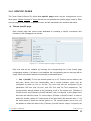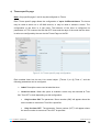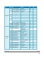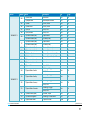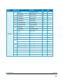
1
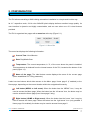
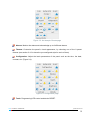
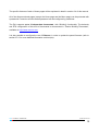
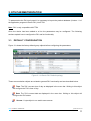
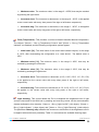
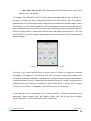
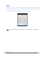
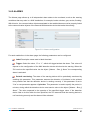
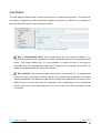
PRODUCT MANUAL INZENNIO Z41 KNX Touch Panel ZN1VI-TP41 Program version: 1.1 Manual edition: a INDEX 1. Introduction ............................................................................................................................................ 3 1.1. InZennio Z41.................................................................................................................................... 3 1.2. Installation ...................................................................................................................................... 5 2. Configuration .......................................................................................................................................... 7 3. ETS Parameterization ............................................................................................................................ 11 3.1. Default configuration..................................................................................................................... 11 3.2. Main configuration ........................................................................................................................ 14 3.2.1. General ..................................................................................................................................... 15 3.2.2. Pages ........................................................................................................................................ 17 3.3. Home and Home 2......................................................................................................................... 18 3.3.1. Icon indicator ............................................................................................................................ 19 3.3.2. Text indicator ............................................................................................................................ 20 3.3.3. 1-button control........................................................................................................................ 22 3.3.4. 2-button control and Icon indicator ........................................................................................... 24 3.3.5. 2-button control and Text indicator........................................................................................... 25 3.4. Menu ............................................................................................................................................ 32 3.4.1. Specific pages............................................................................................................................ 33 a) Climate specific page................................................................................................................. 33 b) Scenes specific page .................................................................................................................. 37 c) Timers specific page .................................................................................................................. 38 3.4.2. Alarms ...................................................................................................................................... 41 3.4.3. Themes ..................................................................................................................................... 43 3.4.4. Configuration ............................................................................................................................ 45 3.4.5. Tools ......................................................................................................................................... 47 Annex I. Communication objects ................................................................................................................... 48 ZENNiO AVANCE Y TECNOLOGÍA _vwww.zennio.com 2 1. INTRODUCTION 1.1. INZENNIO Z41 The InZennio Z41 is a high performance color touch panel. Its use is simple and intuitive and it has a set of features and functions that make it ideal for demanding applications such as hotels, apartments, offices or any situation where it is necessary to manage climate, shutters, lights, scenes, etc. The highlights of the Z41 are listed below: Back-lit 4.1 inch capacitive touch display 16 freely configurable direct access functions Full Climate Management 2 independent thermostats 4 specific pages, to be configured as: Climate control (7 configurable functions per page) Scenes control (up to 8 per page) Timers (only specific pages 3 and 4) 4 generic pages: Alarms (up to 8) Themes Configuration Tools ZENNiO AVANCE Y TECNOLOGÍA _vwww.zennio.com 3 InZennio Z41 is organized into pages. Each page has 8 boxes, and a menu bar. The Z41 has two Home pages, a Menu page, four specific pages (configured as climate, scenes or timers), and alarms, themes, configuration and tools pages. Figure 1.1 shows the Home page of the Z41, where all 8 boxes have been configured to carry out different functions. This manual will detail the correct way to configure and program the InZennio Z41 touch panel, so that a user can control all or part of a KNX installation from a single device. Figure 1.1: InZennio Z41 touch panel ZENNiO AVANCE Y TECNOLOGÍA _vwww.zennio.com 4 1.2. INSTALLATION Figure 1.2 shows the backside of the Z41 identifying its connectors: 9 6 1.- KNX Connection 2.- Programming button 3.- Programming LED 3 2 5 4.- External power supply terminal block 5.- USB connection 7 6.- Ethernet connection 1 7.- Space for a button battery 4 8.- Temperature sensor 9.- Magnet 8 Figure 1.2. Z41 Elements scheme The Z41 connects to the KNX bus via a standard KNX terminal (1). It is also necessary to connect an external 12V, 24V or 29V DC power supply, which supplies at least 150 mA. The KNX bus and the external power supply are electrically isolated in order to prevent possible interference. The external power supply is connected to the Z41 via a screw terminal block (4). Each cable must be correctly connected. The positive of the external power supply connects to the positive (+) of the terminal block and the negative/ground of the power supply connects to the negative (-) of the terminal block. To the Z41 one may connect the supplied USB cable (at the point 5) or the supplied Ethernet adapter (at the point 6), in order to perform an update of the firmware. Please refer to document “Z41 - USB and Ethernet updates”, available at http://www.zennio.com to obtain more detailed information on how to update the Z41 via USB or Ethernet. Z41 includes a conventional LR44 button battery, inserted at the point 7, which will maintain the time and date in the case of a power supply failure. ZENNiO AVANCE Y TECNOLOGÍA _vwww.zennio.com 5 After connecting the external power supply, the panel will flash briefly. After 7 seconds, a loading image appears, with the Zennio logo and “Loading…” 23 seconds later, more or less, a beep will be heard, and the status page will appear (Figure 1.3). Figure 1.3: Status page The box “KNX” shows the physical address assigned to the panel or “x.x.x” if the KNX bus is not connected or the Z41 application has yet to be downloaded. The box “Software” indicates whether the application program is compatible with the Z41 firmware “OK” or not “Error”. The box “Sync” shows the synchronization status of the panel. When it reaches 100%, the Home page of the Z41 will be displayed and the Z41 is ready for use. The box “Ethernet” shows the IP address assigned to the Z41 if the Ethernet cable is connected. The status page will be also shown every time the KNX bus power fails, or the device is reset via ETS or directly from the tools page. Once the panel is connected to the KNX bus, both the physical address and the associated application program can be downloaded using ETS4. A short press of the programming button (2) allows the Z41 to be put in programming mode, at which point the programming LED (3) will glow red. If this button is held while plugging the device into the KNX bus, the Z41 will enter secure mode and the LED will flash red. To obtain more detailed information about the technical features of the Z41, as well as security and installation information, please refer to the touch panel Datasheet, included in the original packaging of the device and also available at: http://www.zennio.com. ZENNiO AVANCE Y TECNOLOGÍA _vwww.zennio.com 6 2. CONFIGURATION The Z41 allows controlling a KNX building automation installation in a simple and intuitive way. Its 4.1" capacitive touch, 24 bit color 240x320 pixels display delivers excellent image quality. Its user interface is dynamic and highly customizable, and one can select one of 8 visual themes provided. The Z41 is organized into pages with a menu bar at the top (Figure 2.1). Figure 2.1: Menu Bar The menu bar displays the following information: Current Time: Hour:Minutes. Date: Day/Month/Year. Temperature: The current temperature, in ºC, of the room where the panel is installed. This temperature is obtained from the internal sensor of the Z41, located at the bottom of the panel (figure 1.2). Name of the page: The label bottom centre displays the name of the current page (name established in ETS by parameter). It also has two buttons which allow access to the Menu page, Home page 2 (if enabled) or the Home page, depending on the current location within the navigational hierarchy. Left button (MENU or Left arrow): When the button has the “MENU” icon, it may be used to access the Menu page. When the button has the ‘left arrow’ icon, the button may be used to access the Home page (from Home page 2 only). Right button (HOME or Right arrow): When the button has the ‘home’ icon it may be used to access the Home page. When the button has the ‘right arrow’ icon (only possible if Home page 2 is enabled), the button may be used to access Home page 2. ZENNiO AVANCE Y TECNOLOGÍA _vwww.zennio.com 7 The touch panel has a built-in temperature sensor, with an associated communication object, which allows periodically sending the Z41’s current ambient temperature. The Z41 allows configuring two independent Home pages each of which may have up to 8 boxes, configured to have different functionality, depending on the needs of the installation. After a download or a reset, the Z41 shows the Home page as the principal page. The Z41 has also a Menu page, enabled by default, allowing access to every page configured in ETS, by pressing the button in the corresponding box (Figure 2.2). Figure 2.2: Menu page These pages are as follows: 4 specific pages; Climate (Figure 2.3), Scenes or Timers. ZENNiO AVANCE Y TECNOLOGÍA _vwww.zennio.com 8 Figure 2.3: An example Climate page Alarms: Monitor the status and acknowledge up to 8 different alarms. Themes: Customize the panel’s visual appearance, by choosing one of the 8 preset themes (see section 3.4.3 to know the pre-configured style for each of them). Configuration: Adjust the basic parameters of the panel such as the time, the date, contrast, etc. (Figure 2.4). Figure 2.4: Configuration page Tools: Programming LED control and device RESET. ZENNiO AVANCE Y TECNOLOGÍA _vwww.zennio.com 9 The specific features of each of these pages will be explained in detail in section 3.4 of this manual. All of the aforementioned pages (except the Home page and the Menu page) can be protected with a password. Protection and the default password can be configured by parameter. The Z41 supports up to 2 independent thermostats, with “Building” functionality. The behavior and ETS configuration of this kind of thermostat is documented in “Zennio Building Thermostat”, available at: http://www.zennio.com. It is also possible to configure the use of Ethernet, in order to update the panel firmware (refer to section 3.2.1 for more detailed information on this topic). ZENNiO AVANCE Y TECNOLOGÍA _vwww.zennio.com 10 3. ETS PARAMETERIZATION To parameterize the Z41 touch panel it is necessary to import the product database (Version 1.1 of the application program InZennio Z41) into ETS4. Note: Z41 is only compatible with ETS4. Once the device has been added to a line the parameters may be configured. The following sections explain how to configure the Z41 and its functionality. 3.1. DEFAULT CONFIGURATION Figure 3.1 shows the factory default group objects before configuring the parameters. Figure 3.1: InZennio Z41 Default topology These communication objects are related to general Z41 functionality and are described below: Time: The Z41’s current time of day as displayed in the menu bar. Writing to this object will configure the Z41’s time of day. Date: The Z41’s current date as displayed in the menu bar. Writing to this object will configure the Z41’s date. Scenes: 1-byte object to run and/or save scenes. ZENNiO AVANCE Y TECNOLOGÍA _vwww.zennio.com 11 Temperature: The current ambient room temperature as measured by the Z41’s internal sensor. This object is periodically sent to the bus. Illumination: The Z41’s backlight will automatically switch off after a pre-determined time to preserve energy and also to avoid being an unwanted source of light. Writing the value “1” to this 1-bit object will illuminate the display. Writing the value "0" has no effect. Touch block: This 1-bit object may be used to enable or disable user input to the Z41. Writing the value “1” to this object will disable user input causing the Z41 to ignore all presses of the touch screen. Writing the value “0” to this object will enable touch input and the Z41 will respond once again to user input. When editing InZennio Z41’s parameters for the first time the following parameter configuration window can be seen: Figure 3.2: Default parameterization screen As can be seen in figure 3.2, the parameterization screen has five sections, enabled by default. These are: Main configuration: Divided into two sections: General: To configure the following general features of the Z41: Power supply voltage, internal temperature sensor, default theme, Ethernet and thermostats. ZENNiO AVANCE Y TECNOLOGÍA _vwww.zennio.com 12 Pages: To enable Home page 2, to set the weekday initials as displayed on the timers page and timer configuration dialog, and to configure the security password and the security dialog text prompts. Home: To enable and configure each of the 8 Home page boxes. Menu: To enable the pages that are accessed using the Menu Page, and to configure whether those pages are protected by a security password dialog. The pages accessed using the Menu Page are the four specific pages, and the alarms, scenes, themes, configuration and tools pages. The last two are enabled by default. Configuration page: To enable and configure boxes related to changing the time, date, brightness, contrast and melody. The last three are enabled by default. Tools: To enable and configure boxes related to factory reset and the enabling and disabling of the programming LED from the panel (enabled by default). ZENNiO AVANCE Y TECNOLOGÍA _vwww.zennio.com 13 3.2. MAIN CONFIGURATION The main configuration is split into ‘General’ configuration and ‘Pages’ configuration as illustrated in Figures 3.3 and 3.4 respectively. General functionality can be enabled and configured, such as the thermostats and default theme, and also Home page 2 can be enabled. The Home page and Menu page are enabled by default and this cannot be changed. The default password is also specified here as are the texts used by the security dialog to prompt the user. Detailed information on each of the two configurations follows. Figure 3.3: General configuration Figure 3.4: Pages configuration ZENNiO AVANCE Y TECNOLOGÍA _vwww.zennio.com 14 3.2.1. GENERAL Each of the configuration options are described below: Power supply voltage: Select by parameter the voltage of the external power supply connected to the Z41. The options are 12V, 24V or 29V. This parameter only affects the management of the internal temperature sensor and has no other purpose. Internal temperature sensor: Selecting this option allows configuration of the following parameters related to the Z41’s built-in temperature sensor: Figure 3.5: Internal temperature sensor parameters Sensor calibration: Specify an offset (in tenths of a degree) to compensate for a fixed deviation between the actual ambient room temperature and that measured by the Z41. Sending period: Select by parameter the time (in tens of seconds) to send cyclically to the KNX bus the current temperature measurement, via the communication object "[General] Temperature". The value 0 indicates that periodic sending is disabled. Send with a temperature change: The Z41 will send to the KNX bus the current temperature when it has changed (increased or decreased) with regard to the last measurement by the amount specified in this parameter (tenths of a degree). To disable this feature, specify 0 in this field. Default theme (after programming): Select the default visual theme the Z41 will use after programming or a reset device. There are 8 themes available, refer to section 3.4.3 for further details. ZENNiO AVANCE Y TECNOLOGÍA _vwww.zennio.com 15 Ethernet: On selecting this option a new configuration window will be shown in the left menu (Figure 3.6). Figure 3.6: Ethernet connection configuration In this window, it will be possible to configure the following options, related to the Ethernet connection: Device description: A string of up to 40 characters, to identify the Z41 panel. Providing a descriptive name is necessary in installations where there are several Z41s connected to the same local area network (LAN), so that each Z41 may be indentified when updating their firmware via Ethernet. IP Address assignment: Fixed to DHCP. A DHCP server will automatically assign an IP address to the panel. Note I: Ethernet cable must be connected before the panel starts. Note II: It is necessary that the panel is connected to a DHCP (Dynamic Host Configuration Protocol) server to carry out the automatic IP address assignment. If the panel is connected to an Ethernet network, and it has been assigned an IP address, it is possible to perform an upgrade of the firmware via the network. Please refer to “Z41 – USB and Ethernet updates” available at http://www.zennio.com for more details. ZENNiO AVANCE Y TECNOLOGÍA _vwww.zennio.com 16 Thermostats: On selecting any of the two available thermostats, one (or two) new configuration windows will be shown in the left menu (Figure 3.7). Figure 3.7: Thermostat 1 configuration To obtain information about the Zennio thermostat and its ETS configuration, please consult the document "Thermostat Zennio" available at: http://www.zennio.com. 3.2.2. PAGES The ‘Pages’ configuration provides the option to enable Home page 2. This page has the same functionality as the Home page and detailed information regarding Home page configuration can be found in section 3.3. As mentioned earlier, it is not possible to disable the Menu page or the Home Page. The default security password is also specified here and additionally various texts related to the timers and security dialogs: Weekday initials: Specify 7 characters to use as the weekday initials. Only capital letters and numbers can be used. By default this parameter is “MTWTFSS”. The weekday initials are used in the timers page and the timer configuration dialog to identify the days of the week. Password: Configure the default password by specifying 4 digits (0…9). The password is necessary to access protected pages. Each page except the Home and Menu pages may have access protected by a password. The default password is 1234. It can be changed directly from the panel by pressing the button that appears at the bottom left of the password keypad and following the instructions Figure 3.8. ZENNiO AVANCE Y TECNOLOGÍA _vwww.zennio.com 17 Security pad labels: Specify the text used by the security dialog to prompt the user. By default: “Enter Password”, “ERROR”, “New Password”, “Repeat Password” and “Updated”. Figure 3.8: Password keypad 3.3. HOME AND HOME 2 Each Home page has 8 boxes that may be configured to give direct access to the most commonly used controls and status of a KNX installation, thus simplifying the user experience. Figure 3.9: Home page configuration The Home page is the principal page of the Z41. The Z41 always begins by displaying this page and will return to this page after one minute of inactivity. The one exception to this, is if an alarm has been triggered, in which case the first page to be shown will be the Alarms page. The Home page is enabled by default and it is not possible to protect this page with a password. Either Home page can have up to 8 boxes enabled by selecting the corresponding check box and may be configured as: icon indicator, text indicator, 1-button control, 2-button control and icon indicator or 2-button control and text indicator, except Box 8, which can be only configured as a Scene. ZENNiO AVANCE Y TECNOLOGÍA _vwww.zennio.com 18 All are explained in detail in the following sections. Note: Common to all of the box configurations is the Label field, which can be used to describe the control or indicator and may be found at the bottom of each box. 3.3.1. ICON INDICATOR The boxes configured as an icon indicator will have only an icon in the centre of the box, with a descriptive name at the bottom. The aim of this type of boxes is to show an icon that represents the state of the corresponding communication object. The boxes configured as icon indicator can only be of two types: Binary or Enumeration. Binary: When selecting this option, the 1-bit communication object "[Home x - Box y] Binary Indicator" is enabled, and depending on the value received, "0" or "1", the icon configured for the value "0" (Off Icon) or for the value "1" (On Icon) will be displayed. Refer to the icons list in the document named "Z41 - Icons List", available at http://www.zennio.com. Figure 3.10: Icon indicator: Binary Enumeration: This option allows associating numerical values with icons. When selecting it, the 1-byte object "[Home x - Box y] 1 byte Indicator" is enabled, and the following options are shown: # Enums: Depending on the chosen number, up to 6 value-icon pair boxes will be shown. Value z: A value between 0 and 255 that if received by the object "[Home x - Box y] 1 byte Indicator" will cause the icon specified in “Icon z” to be displayed. Icon z: The icon that will be displayed in the box when the object "[Home x - Box y] 1 byte indicator" receives the value specified in "Value z". ZENNiO AVANCE Y TECNOLOGÍA _vwww.zennio.com 19 Figure 3.11: Icon indicator: Enumeration If the object "[Home x - Box y] 1 byte Indicator" receives a value that does not have an icon associated with it, no icon will be displayed (the box will be empty). For example, given the configuration illustrated in figure 3.11, if the value 100 is received no icon will be displayed. 3.3.2. TEXT INDICATOR The boxes configured as a ‘text indicator’ will have a text or a numerical value in the centre of the box, with a descriptive name at the bottom. The aim of this type of boxes is to show a text or value that represents the state of the corresponding communication object. ZENNiO AVANCE Y TECNOLOGÍA _vwww.zennio.com 20 Figure 3.12: Text indicator The boxes configured as a ‘text indicator’ can be of several types: Binary, Integer (1 byte), Percentage, Enumeration, Integer (2 bytes) and Float. Binary: The 1-bit communication object "[Home x - Box y] Binary Indicator" is enabled, and depending on the value received, "0" or "1", the text configured for the value "0" (Off Text) or for the value "1" (On Text) will be displayed. Integer (1 byte): The 1-byte communication object "[Home x - Box y] 1 byte Indicator" is enabled and the state of this object, 0…255, will be displayed. After downloading parameters or a ‘reset device’ command the value displayed will be 0, until the object is updated. Percentage: The 1-byte communication object "[Home x - Box y] Scaling Indicator" is enabled and the state of this object, 0…255, will be converted to a percentage within the range 0…100 and displayed with a trailing ‘%’ symbol. After downloading parameters or a ‘reset device’ command the value displayed will be 0%, until the object is updated. Enumeration: This option allows associating numerical values with texts. When selecting it, the 1-byte object "[Home x - Box y] 1 byte Indicator" is enabled, and the following options are shown: # Enums: Depending on the chosen number, up to 6 value-text pair boxes will be shown. Value z: A value between 0 and 255 that if received by the object "[Home x - Box y] 1 byte Indicator" will cause the text specified in “Text z” to be displayed. Text z: The text that will be displayed in the box when the object "[Home x - Box y] 1 byte Indicator" receives the value specified in "Value z". ZENNiO AVANCE Y TECNOLOGÍA _vwww.zennio.com 21 If the object "[Home x - Box y] 1 byte Indicator" receives a value that does not have a text associated with it, no text will be displayed (the box will be empty). Integer (2 bytes): The 2-bytes communication object "[Home x - Box y] 2 byte Indicator" is enabled and the state of this object, 0…65535, will be displayed. After downloading parameters or a ‘reset device’ command the value displayed will be 0, until the object is updated. Float: The 2-bytes communication object "[Home x - Box y] Float Indicator" is enabled, and the state of this object, -67108864…67076096, will be displayed. After downloading parameters or a ‘reset device’ command the value displayed will be 0, until the object is updated. 3.3.3. 1-BUTTON CONTROL The boxes parameterized as a ‘1-button control’ will have a button in the centre, whose icon can be configured via the parameter "Button (In the middle)". This is a generic control used to communicate with KNX devices that are manipulated via their objects. Figure 3.13: 1-button control The boxes configured as a ‘1-button control’ can be of several types: Binary, Integer (1 byte) and Scene. Binary: When selecting this option, two new 1-bit communication objects will be shown: "[Home x - Box y] Binary Control" and "[Home x - Box y] Binary Indicator", which allow the Z41 to manipulate KNX devices by sending a binary value "0" or "1". One of the following behaviors can be selected for the 1-button control: ZENNiO AVANCE Y TECNOLOGÍA _vwww.zennio.com 22 Toggle: Every time the button is pressed (short press), the value “1” or “0” will be sent to the KNX bus via the object "[Home x -Box y] Binary Control". The value sent will be the opposite of its current value. I.e. if the current value is “0” a “1” will be sent and vice versa. 0: Every time the button is pressed (short press), “0” will be sent via the object "[Home x -Box y] Binary Control". 1: Every time the button is pressed (short press), “1” will be sent via the object "[Home x -Box y] Binary Control". Short 1 - Long 0: A short press of the button will send the value “1” to the bus via the object "[Home x - Box y] Binary Control", whereas a long press will send the value "0". Short 0 - Long 1: A short press of the button will send the value “0” to the bus via the object "[Home x - Box y] Binary Control", whereas a long press will send the value "1". Integer (1 byte): On selecting this option the 1-byte object "[Home x - Box y] 1 byte Control" is enabled, via which the numerical value (0…255) parameterized in the field "Fixed Value" will be sent to the KNX bus when the button is pressed (short press). Scene: This option allows running and/or saving scenes. To run the scene, press the button (short press). To save a scene, press the button and maintain the press for at least 3 seconds. It is necessary to configure the following options: Function: There are two options; ‘Run’ or ‘Run and Save’. The first option only allows scenes to be executed. The second option additionally allows the current state of those KNX devices associated with the specified scene to be saved. On executing a scene the scene number will be sent to the bus via the object "[General] Scenes". On saving a scene the scene number with the ‘save’ flag will be sent. Scene number: Numerical value between 1 and 64. ZENNiO AVANCE Y TECNOLOGÍA _vwww.zennio.com 23 3.3.4. 2-BUTTON CONTROL AND ICON INDICATOR The boxes parameterized as ‘2-button control and icon indicator’ will have two control buttons, one on the left and another on the right side of the box, whose icons can be configured via the parameters "Left Button" and "Right Button", respectively. Figure 3.14: 2-button control and icon indicator This is generic control used to communicate with KNX devices that are manipulated via their objects. In addition it is possible to view the current status of the KNX device reflected by the central icon indicator. The boxes configured as a ‘2-button control and icon indicator’ can be one of two types; Binary or Enumeration. Binary: When selecting this option, two new 1-bit communication objects will be shown: "[Home x - Box y] Binary Control" and "[Home x - Box y] Binary Indicator", which allow the Z41 to manipulate KNX devices by sending a binary value "0" or "1". One of the following behaviors can be selected: Left 0 - Right 1: Every time the left button is pressed (short press), the value "0" will be sent to the bus via the object "[Home x - Box y] Binary Control" and the icon configured in "Off Icon" will be displayed. Every time the right button is pressed (short), the value "1" will be sent and the icon configured in "On Icon" will be displayed. Left 1 - Right 0: Every time the left button is pressed (short press), the value "1" will be sent to the bus via the object "[Home x - Box y] Binary Control" and the icon configured in "Off Icon" will be displayed. Every time the right button is pressed (short), the value "0" will be sent and the icon configured in "On Icon" will be displayed. ZENNiO AVANCE Y TECNOLOGÍA _vwww.zennio.com 24 Enumeration: This option allows associating numerical values with icons. When selecting it, two new 1-byte communication objects will be shown: "[Home x - Box y] 1 byte Control" and "[Home x - Box y] 1 byte Indicator". The behavior of this type of control is as follows: First configure the parameter "# Enums" the number of value-icon pairs (1 to 6), and then specify the value-icon pairs using fields "Value z" and "Icon z", respectively (refer to 3.3.1). After downloading the desired configuration, the icon displayed in the box will the one associated with the Value 1, i.e., the icon specified by the parameter (Icon 1). If the right button is pressed (short press), the icon displayed as well as the value sent to the bus will be the next value-icon pair. When the last value-icon pair is reached the control will wrap to the first value-icon pair, e.g. 2-3-4-5-6-1-2-3… If the left button is pressed (short press), the icon displayed as well as the value sent to the bus will be the previous value-icon pair. When the first value-icon pair is reached the control will wrap to the last value-icon pair, e.g. 6-5-4-3-2-1-6-5... The icon can be modified via the KNX bus if the object "[Home x - Box y] 1 byte Indicator" receives a value that has an icon associated with it. If this object receives a value that does not have an icon associated no icon will be displayed. Note: Each value-icon pair must have a unique value. It is not a valid configuration if two or more value-icon pairs share the same value, and the behavior of the control in this case is undefined. 3.3.5. 2-BUTTON CONTROL AND TEXT INDICATOR The boxes parameterized as ‘2-button control and text indicator’ will have two control buttons, one on the left and another on the right side of the box, whose icons can be configured via the parameters "Left Button" and "Right Button", respectively. ZENNiO AVANCE Y TECNOLOGÍA _vwww.zennio.com 25 Figure 3.15: 2-button control and text indicator This is generic control used to communicate with KNX devices that are manipulated via their objects. In addition it is possible to view the current status of the KNX device reflected by the central text indicator.. The boxes configured as ‘2-button control and text indicator’ can be of several types: Binary, Integer (1 byte), Percentage, Enumeration, Integer (2 bytes), Float (Temperature), Light dimming and Shutter control. Binary: When selecting this option, two new 1-bit communication objects will be shown: "[Home x - Box y] Binary Control" and "[Home x - Box y] Binary Indicator", which allow the Z41 to manipulate KNX devices by sending a binary value "0" or "1". One of the following behaviors can be selected: Left 0 - Right 1: Every time the left button is pressed (short press), the value "0" will be sent to the bus via the object "[Home x - Box y] Binary Control" and the text configured in "Off Text" will be displayed. Every time the right button is pressed (short), the value "1" will be sent and the text configured in "On Text" will be displayed. Left 1 - Right 0: Every time the left button is pressed (short press), the value "1" will be sent to the bus via the object "[Home x - Box y] Binary Control" and the text configured in "Off Text" will be displayed. Every time the right button is pressed (short), the value "0" will be sent and the text configured in "On Text" will be displayed. Integer (1 byte): This option allows the Z41 to communicate with the rest of devices in the installation by sending a byte (0…255). When selecting this option, two new 1-byte ZENNiO AVANCE Y TECNOLOGÍA _vwww.zennio.com 26 communication objects will be shown: "[Home x - Box y] 1 byte Control" and "[Home x - Box y] 1 byte Indicator", and the following configuration options appear: Initial value: The initial value of the control and indicator objects, in the range 0…255, after downloading the configuration or a ‘reset device’. Minimum value: The minimum value, in the range 0…255, that may be reached by pressing the left button. Maximum value: The maximum value, in the range 0…255, that may be reached by pressing the right button. Increment short: The increment or decrement, in the range 0…127, to be applied to the current value with every short press of the right or left button, respectively. Increment long: The increment or decrement, in the range 0…127, to be applied to the current value with every long press of the right or left button, respectively. Percentage: This option allows the Z41 to communicate with the rest of devices in the installation by sending a byte (0…255) representing a percentage value between 0 and 100%. When selecting this option, two new 1-byte communication objects will be shown: "[Home x - Box y] 1 byte Control" and "[Home x - Box y] 1 byte Indicator", and the following configuration options appear: Initial value (%): The initial value of the control and indicator objects, in the range 0…100%, after downloading the configuration or a ‘reset device’. Minimum value (%): The minimum value, in the range 0…100%, that may be reached by pressing the left button. Maximum value (%): The minimum value, in the range 0…100%, that may be reached by pressing the right button. Increment short (%): The increment or decrement, in the range 0…100%, to be applied to the current value with every short press of the right or left button, respectively. Increment long (%): The increment or decrement, in the range 0…100%, to be applied to the current value with every long press of the right or left button, respectively. ZENNiO AVANCE Y TECNOLOGÍA _vwww.zennio.com 27 Enumeration: This option allows associating numerical values with texts. When selecting it, two new 1-byte communication objects will be shown: "[Home x - Box y] 1 byte Control" and "[Home x - Box y] 1 byte Indicator". The behavior of this type of control is as follows: First configure the parameter "# Enums" the number of value-text pairs (1 to 6), and then specify the value-text pairs using fields "Value z" and "Icon z", respectively (refer to 3.3.1). After downloading the desired configuration, the text displayed in the box will the one associated with the Value 1, i.e., the text specified by the parameter (Icon 1). If the right button is pressed (short press), the text displayed as well as the value sent to the bus will be the next value-text pair. When the last value-text pair is reached the control will wrap to the first value-text pair, e.g. 2-3-4-5-6-1-2-3… If the left button is pressed (short press), the text displayed as well as the value sent to the bus will be the previous value-text pair. When the first value-text pair is reached the control will wrap to the last value-text pair, e.g. 6-5-4-3-2-1-6-5... The text can be modified via the KNX bus if the object "[Home x - Box y] 1 byte Indicator" receives a value that has an text associated with it. If this object receives a value that does not have an text associated no text will be displayed. Note: Each value-text pair must have a unique value. It is not a valid configuration if two or more value-text pairs share the same value, and the behavior of the control in this case is undefined. Integer (2 bytes): This option allows the Z41 to communicate with the rest of devices in the installation by sending a 2-bytes value (0…65535). When selecting this option, two new 1byte communication objects will be shown: "[Home x - Box y] 2 byte Control" and "[Home x Box y] 2 byte Indicator", and the following configuration options appear: Initial value: The initial value of the control and indicator objects, in the range 0…65535, after downloading the configuration or a ‘reset device’. Minimum value: The minimum value, in the range 0…65535, that may be reached by pressing the left button. ZENNiO AVANCE Y TECNOLOGÍA _vwww.zennio.com 28 Maximum value: The maximum value, in the range 0…65535, that may be reached by pressing the right button. Increment short: The increment or decrement, in the range 0…32767, to be applied to the current value with every short press of the right or left button, respectively. Increment long: The increment or decrement, in the range 0…32767, to be applied to the current value with every long press of the right or left button, respectively. Float (Temperature): This provides a control orientated towards absolute temperature. The objects "[Home x - Box y] Temperature Control" and "[Home x - Box y] Temperature Indicator" are enabled, and the following configuration options appear: Initial value [ºC]: The initial value of the control and indicator objects, in the range 0…95ºC, after downloading the configuration or a ‘reset device’. The default value is 25ºC. Minimum value [ºC]: The minimum value, in the range 0…95ºC, that may be reached by pressing the left button. Maximum value [ºC]: The maximum value, in the range 0…95ºC, that may be reached by pressing the right button. Increment short: The increment or decrement (0.1ºC, 0.2ºC, 0.5ºC, 1ºC, 2ºC, 5ºC) to be applied to the current value with every short press of the right or left button, respectively. Increment long: The increment or decrement (0.1ºC, 0.2ºC, 0.5ºC, 1ºC, 2ºC, 5ºC) to be applied to the current value with every long press of the right or left button, respectively. Light dimming: This control allows the Z41 to manipulate the brightness level of light sources connected to the KNX bus by sending and receiving values via the communication objects dedicated to this objective; "[Home x - Box y] Light On/Off" (1-bit object), "[Home x Box y] Light Indicator" (1-byte object) and "[Home x - Box y] Light Dimming" (4-bits object). The parameter Dimming step indicates the increment or decrement of the brightness level to be applied with each button press/step. Table 3.1 summarizes the available dimming steps. ZENNiO AVANCE Y TECNOLOGÍA _vwww.zennio.com 29 The light dimming operates as follows: Short press: For each short press of the left button, the value "0" will be sent to the bus via the object "[Home x - Box y] Light On/Off" thus making the light source switch off (if the KNX device has been configured to behave this way when receiving the value "0"). For each short press of the right button, the value "1" will be sent, thus making the light source switch on (if the KNX light source has been configured to behave this way when receiving the value "1"). Long press: On a long press of the left button, the order to decrease the brightness level by the dimming step will be sent via the object "[Home x - Box y] Light Dimming". When the button is released, the order to stop decreasing the brightness level is sent. On a long press of the right button, the order to increase the brightness level by the dimming step will be sent via the object "[Home x - Box y] Light Dimming". When the button is released, the order to stop increasing the brightness level is sent. The object "[Home x - Box y] Light Indicator" must be linked, with the same group address, to a status object that reflects the brightness level of the light source to control, in order to update the percentage indicator that appears in the centre of the box with the current brightness level. Dimming step 100% 50% 25% 12.5% 6.25% 3.1% 1.5% Number of steps for complete regulation (0-100%) 1 2 4 8 16 32 64 Table 3.1: Dimming step Shutter control: This control allows the Z41 to manage any type of shutter or blind. The following objects are enabled; "[Home x - Box y] Move Shutter" and "[Home x - Box y] Stop Shutter", 1-bit each. These objects control the raising/lowering or stopping of the shutter, respectively. The 1-byte object "[Home x - Box y] Shutter Position" allows the shutter to provide feedback to the Z41 of its exact position at any given moment. ZENNiO AVANCE Y TECNOLOGÍA _vwww.zennio.com 30 The shutter control operates as follows: Short press: On a short press of the left button, the value "1" will be sent via the object "[Home x - Box y] Stop Shutter", thus making the shutter stop. On a short press of the right button, the value "0" will be sent via the same object and this will also stop the shutter. If the shutter is already stationary, a short press will have no action. Long press: If the left button is long-pressed, the value "1" will be sent through the object "[Home x - Box y] Move Shutter", thus making the shutter move down, until it completes its length or until receiving a stop order via the corresponding object. If the right button is long-pressed, the value "0" will be sent via the object "[Home x - Box y] Move Shutter", thus making the shutter move up, until it completes its length or until receiving a stop order via the corresponding object. The object "[Home x - Box y] Shutter Position" must be linked, with the same group address, to a status object that shows the current position (in percentage) of the shutter to control, in order to update the percentage indicator that appears in the centre of the box with the current shutter position. Note: The value 0% indicates that the shutter is completely up, whereas the value 100% indicates that the shutter is completely down. ZENNiO AVANCE Y TECNOLOGÍA _vwww.zennio.com 31 3.4. MENU The Menu page is always enabled. From the menu page configuration, up to four specific pages may be enabled and configured, as well as the alarms, themes, configuration, and tools pages. These last two are enabled by default. Figure 3.16: Menu page configuration As can be seen in figure 2.2, the Menu page dedicates a box to accessing each of the pages enabled in the menu configuration. The label specified for each page is used as the box’s label to describe the destination page on pressing the box’s button. It is possible to protect each of the pages accessed via the Menu page with a password. In the case that a page is protected, a password dialog will be displayed prompting the user for the password. If the password entered is correct the desired page will be displayed. If however the password is incorrect, focus will return to the Menu page. The locations of the boxes dedicated to accessing each destination page are fixed. The first four boxes are for the specific pages, the fifth for the alarms page, the sixth for the themes page, the seventh for the configuration page, and the eighth for the tools page. Each of these pages is described in the following sections. Note: Note that the button icons are fixed and are not configurable, and also that if a page is not enabled the corresponding box is empty. ZENNiO AVANCE Y TECNOLOGÍA _vwww.zennio.com 32 3.4.1. SPECIFIC PAGES The Touch Panel InZennio Z41 offers four specific pages which may be configured as one of three types: Climate, Scenes or Timers (timers are only available for specific pages 3 and 4). Each of these pages is dedicated to a specific function and are described in the sections that follow: a) Climate specific page Each climate page has seven boxes dedicated to providing a simple, convenient user interface for the management of climate. Figure 3.17: Climate specific page configuration Each box and can be enabled by checking the corresponding box in the climate page configuration window. If a feature is not enabled, the corresponding box on the page will be empty. Each of the boxes and their functionality is described below: Box 1 (On/Off): To turn the climate system on or off. This box has two buttons, left and right, whose icons are customizable, and a central indicator, which may be configured as either an icon or as text. The icons and text are configured by the parameters “Off Icon” and “On Icon”, and “Off Text” and “On Text” respectively. The communication objects related to the switching on/off of the system are: "[Climate x] On/Off Control" and "[Climate x] On/Off Indicator", both 1-bit objects. A short press of the left button will send the value “0” via the object "[Climate x] On/Off Control" in order to switch the climate system off. A short press of the right button will send the value “1” via the same object to switch the climate system on. The central indicator, text or icon, will be updated to reflect the state of the "[Climate x] On/Off Control" object. If required, the ZENNiO AVANCE Y TECNOLOGÍA _vwww.zennio.com 33 climate system can provide feedback of its on/off state by updating the object "[Climate x] On/Off Indicator", and the indicator will be updated to reflect the new state of this object. Box 2 (Temperature): This control allows the temperature setpoint to be configured by the user. This setpoint value can be established in 3 different ways: Absolute temperature: The 2-bytes object "[Climate x] Temperature Control" is enabled, in order to send the desired setpoint to the climate system. Long or short presses of the left (decrease) and right (increase) buttons allow the desired setpoint to be established. A short press will increment or decrement the current value by 0.5ºC, and a long press by 1ºC. Upper and lower limits must be specified (ºC) in order that the temperature range of the control may be bounded. Additionally the object "[Climate x] Temperature Indicator" may be used to set the setpoint value externally, for example to synchronize the setpoint amongst many Z41s in the same climate zone. Relative temperature (1-bit object): The 1-bit object "[Climate x] Temperature Offset Control" is enabled. A short press of the right or left button will increment or decrement, respectively, the current setpoint, by the value specified in the parameter “Offset” in tenths of a degree. After each press, the setpoint value will be updated by the offset and the new value will be displayed in the centre of the box, while the value “0” (decrement) or “1” (increment) will be sent to the bus. Additionally the object "[Climate x] Temperature Indicator" may be used to set the setpoint value externally. Relative temperature (float object): The 2-bytes object "[Climate x] Temperature Control" is enabled, in order to increment/decrement (depending on the button pressed: left/right) the value of the current setpoint in 0.5ºC, respectively. Only short pressings are available. After every pressing, the setpoint value will be updated with the new offset and will be shown in the centre of the box, and the value of the offset applied with every pressing will be sent to the bus. It is possible to configure by parameter the minimum and maximum offset that can be applied to the setpoint (values between -15ºC and 15ºC). Additionally the object "[Climate x] Temperature Indicator" may be used to set the setpoint value externally. Box 3 (Mode): Allows selection of the operational mode of the climate system. There are two options: ZENNiO AVANCE Y TECNOLOGÍA _vwww.zennio.com 34 Heat/Cool: The climate mode may be either Heat or Cool. A short press of the left button selects Cool mode and the value “0” is sent via the 1-bit control object "[Climate x] Mode Control". Conversely a short press of the right button selects Heat mode and the value “1” is sent. The climate system can provide feedback by sending the corresponding Heat/Cool value to the 1-bit indicator object "[Climate x] Mode Indicator". The central indicator icon will always reflect the current mode. Extended: In addition to the climate modes Heat and Cool, the modes, Auto, Fan and Dry are available. Each may be enabled or disabled by checking or unchecking its respective checkbox. By default all modes are enabled. A short press of the left or right button will cycle through the enabled modes, and the value associated with the current mode will be sent via the 1-byte control object "[Climate x] Mode Control". The values associated with each mode are summarized in table 3.2: Mode Auto Heating Cooling Fan Dry Value 0 1 3 9 14 Table 3.2: Climate mode values The climate system can provide feedback by sending the corresponding value to the 1-byte indicator object "[Climate x] Mode Indicator". The central indicator icon will always reflect the current mode, unless the value received by the indicator object is not one of the values in table 3.2, in which case no icon will be displayed. Box 4 (Fan): The fan speed control is a "1-bit" control to request either an increase or a decrease of the fan speed. A short press of the left button will send the value “0” via the control object "[Climate x] Fan Control" resulting in a decrease in of the fan speed. A short press of the right button will send the value “1” resulting in an increase in of the fan speed. The object "[Climate x] Fan Indicator" may be used by the climate system to provide feedback of the actual fan speed, with the central indicator icon displayed depending on both the state of the object and on the parameter “Fan” as illustrated in table 3.3: ZENNiO AVANCE Y TECNOLOGÍA _vwww.zennio.com 35 Fan parameter value Fan state - Icon relationship Min/Max Min/Med/Max Auto/Min/Med/Max Off/Min/Med/Max 0-49%=Min Icon; 50-100%=Max Icon 0-33%=Min Icon; 34-66%=Med Icon; >67%=Max Icon 0=Auto Icon; 1-33%=Min Icon; 34-66%=Med Icon; >67%=Max Icon 0=Off Icon; 1-33%=Min Icon; 34-66%=Med Icon; >67%=Max Icon Table 3.3: Fan state - icon relationship Box 5 (Binary 1): On enabling this box, two new 1-bit communication objects appear: "[Climate x] Binary 1 Control" and "[Climate x] Binary 1 Indicator", which may be linked to other 1-bit objects in order to control binary functions of the climate system. This box has two buttons, left and right, whose icons are customizable, and a central indicator, which may be configured as either an icon or a text indicator. The icons and text are configured by the parameters “Off Icon” and “On Icon”, and “Off Text” and “On Text” respectively. Box 6 (Binary 2): Similar to the Binary 1 control, however the objects enabled are "[Climate x] Binary 2 Control" and "[Climate x] Binary 2 Indicator". Box 7 (Special Modes): By enabling this box, it will be possible to switch from one special climate mode to another, the modes being; Comfort, Standby and Economy. The left and right button, whose icons may be customized, allow cycling through the available special modes, with the associated special mode value being sent to the climate system via the control object "[Climate x] Special Mode Control". The climate system can provide feedback by sending the corresponding special mode value to the indicator object "[Climate x] Special Mode Indicator". The central indicator icon will always reflect the current mode, unless the value received by the indicator object is not valid, in which case no icon will be displayed. ZENNiO AVANCE Y TECNOLOGÍA _vwww.zennio.com 36 b) Scenes specific page Each Scene specific page allows the configuration of up to 8 different scenes. Figure 3.18: Scenes specific page configuration Each box that is enabled has a button in the centre, whose icon may be configured by parameter, and a descriptive name used as the box’s label. In addition the following parameters must be configured: Number: Numerical value between 1 and 64, associated to a scene. Action: There are two options; ‘Run’ or ‘Run and Save’. The first option only allows scenes to be executed. The second option additionally allows the current state of those KNX devices associated with the specified scene to be saved. On executing a scene the scene number will be sent to the bus via the object "[General] Scenes". On saving a scene the scene number with the ‘save’ flag will be sent. Icon: To select the button icon (Refer to the icons list in the document "Z41 - Icons List", available at http://www.zennio.com). To run the scene, press the button (short press). To save a scene, press the button and maintain the press for at least 3 seconds. ZENNiO AVANCE Y TECNOLOGÍA _vwww.zennio.com 37 c) Timers specific page Note: Only specific pages 3 and 4 may be configured as Timers. Each Timers specific page allows the configuration of up to 8 different timers. The timers may be used to switch on or off KNX devices, or may be used to activate a scene. The configuration of the timer is in two parts. The behavior of the timer is configured via parameters in ETS, however the ON and OFF times and the days of the week that the timer is active are configured by the user via the Timers Page on the Z41. Figure 3.19: Timers specific page configuration Each enabled timer has its own 1-bit control object: “[Timers 3 (or 4)] Timer x”, and the following parameters can be configured: Label: Descriptive name used to label the timer. Linked to scene: When this option is enabled a scene may be executed at Time ON, Time OFF or both depending on this configuration: Only for timer ON: The parameter “Scene number (ON)” will appear where the scene number to execute at Time ON is specified. Only for timer OFF: The parameter “Scene number (OFF)” will appear where the scene number to execute at Time OFF is specified. ZENNiO AVANCE Y TECNOLOGÍA _vwww.zennio.com 38 Both timer ON and OFF: Both parameters “Scene Number (On)” and “Scene Number (Off)” will appear. To configure Time ON and Time OFF, and the days of the week that the timer is active, it is necessary to access the timer configuration dialog on the Z41 (Figure 3.20). This dialog is accessed from the Timers specific page, which is itself accessed from the Menu page. On the Timers page, any timer that is enabled by ETS configuration will have a corresponding box with a descriptive label. If the timer box only has the descriptive label, this signifies that the timer is currently inactive. Those timers that are active will display the active days, Time ON and Time OFF in the box. Pressing an enabled timer’s box provokes the timer configuration dialog to appear. Figure 3.20: Timer configuration default dialog The days of the week that the timer is active may be chosen by ticking the required checkboxes. To enable the Time ON and Time OFF events their respective checkbox must be ticked. If enabled it is possible to adjust the time using the respective up and down buttons to modify the time (24 Hour). A short press will modify the time by 1 minute, a long press will modify the time by 10 minutes. If enabled, at Time ON the value “1” will be sent via object “[Timers 3 (or 4)] Timer x”. If enabled, at Time OFF the value “0” will be sent. In the case the timer is configured to be “Linked to scene”, The scene specified by the parameters “Scene number (On)” and “Scene number (Off)” will be sent via the object “[General] Scenes”, at Time ON and Time OFF, respectively. ZENNiO AVANCE Y TECNOLOGÍA _vwww.zennio.com 39 Example. Assuming box 1 of the Timers specific page 3 has been configured as shown in the image below, and without linking it to scenes. This timer will be active on Tuesdays, Wednesdays and Thursdays and the Z41 will send the value “1” at 7:30 a.m. and the value “0” at 22:30 p.m. to the KNX bus via the object “[Timers 3] Timer 1” on these days. Note: A timer may be deactivated by unchecking the Time ON and Time OFF checkboxes. ZENNiO AVANCE Y TECNOLOGÍA _vwww.zennio.com 40 3.4.2. ALARMS The Alarms page allows up to 8 independent alarm states to be monitored, such as the warning conditions that may arise in a KNX installation, for example, broken window, gas, smoke, flooding. With this aim, the communication objects associated to the enabled alarms must be properly linked to the communication objects of the external KNX detection device that emits the warning. Figure 3.21: Alarms configuration For each enabled box in the alarm page, the following parameters can be configured: Label: Descriptive name used to label the alarm. Trigger: Select the value, “0” or “1”, which will trigger/activate the alarm. This value will depend on the configuration of the KNX detection device which emits the warning. When the Z41 receives the specified value via the object “[Alarms – Box y] Alarm” the corresponding alarm is activated. Periodic monitoring: The state of the warning device will be periodically monitored by enabling this parameter. This parameter assures the detection of incidents in the quickest time possible and that the detection device is working correctly. If this parameter is set to "Yes" a new parameter appears: Cycle time. This parameter is used to specify the period, in minutes, during which the detection device must send a value to the object “[Alarms – Box y] Alarm”. The value expected is the opposite of the specified trigger value. If the detection device fails to do this within the time specified, the Z41 assumes that the warning device is not functioning correctly and the alarm will be activated. ZENNiO AVANCE Y TECNOLOGÍA _vwww.zennio.com 41 The following describes how the Z41 reacts to an alarm: When the Z41 receives the trigger value via the object “[Alarms – Box y] Alarm”, the corresponding alarm is activated. The Z41 will then display the Alarms page and a danger icon will appear in the corresponding alarm box. The display will begin to flash and a warning “beep” will be emitted to attract the attention of the user. This behavior will continue until the corresponding OK button is pressed, and the alarm is confirmed by sending the value “1” via the object “[Alarms – Box y] Confirmation”. The Z41 will return to its normal state. It is very Important to understand that confirming an alarm does not make the Danger icon disappear from the box affected. This icon will only disappear from the display when the detection device sends its “normal status”, i.e. when the Z41 receives the opposite value to the trigger via the object “[Alarms – Box y] Alarm”. If periodic monitoring is enabled, it will be the detection device which sends this status when danger disappears. ZENNiO AVANCE Y TECNOLOGÍA _vwww.zennio.com 42 3.4.3. THEMES The Themes page allows the user to select the visual appearance of the Z41. There are 8 preconfigured themes which cannot be customized. Figure 3.22: Themes page configuration For each theme that is enabled a box will be displayed with the theme’s description and a button to activate the theme. It is possible to set the name of every enabled theme, by specifying the parameter “Label”. By default, these labels are; “Ocean”, “Sky”, “Night”, “Twilight”, “Egg shell”, “Seaside”, “Rioja” and “Forest”. Figure 3.22 illustrates each of the available themes. Note: After programming, or a ‘reset device’ the Z41 uses the default theme configured in the General section (3.2.1). ZENNiO AVANCE Y TECNOLOGÍA _vwww.zennio.com 43 OCEAN SKY NIGHT TWILIGHT EGG SHELL SEASIDE RIOJA FOREST Figure 3.22: Z41 themes ZENNiO AVANCE Y TECNOLOGÍA _vwww.zennio.com 44 3.4.4. CONFIGURATION The Configuration page allows the user to modify the date and time, display brightness and contrast, and the tone/melody of the beeps. Via parameters, it is possible to enable or disable user modification of these, and to specify the labels associated with each enabled box of the Configuration page. Note: The brightness, contrast and volume are enabled by default. Figure 3.23: Configuration page configuration The configuration and behavior of each is described below: Time: To allow the user to modify the time. Each of the box labels, “Hour (label)” and “Minute (label)” must be specified. The behavior of these boxes is as follows: Hour: This box has two buttons, left and right, with the icons “Minus” and “Plus” respectively. In the centre the hour is displayed. A short press of the left or right button will decrement or increment the hour within the range 0-23. A long press will decrement or increment the hour quicker. Minute: This box has two buttons, left and right, with the icons “Minus” and “Plus” respectively. In the centre the minutes are displayed. A short press of the left or right button will decrement or increment the minutes within the range 0-59. A long press will decrement or increment the minutes quicker. ZENNiO AVANCE Y TECNOLOGÍA _vwww.zennio.com 45 Date: To allow the user to modify the date. Each of the box labels, “Day (label)”, “Month (label)” and “Year (label)” must be specified. The behavior of these boxes is as follows: Day: This box has two buttons, left and right, with the icons “Minus” and “Plus” respectively. In the centre the day of the month is displayed. A short press of the left or right button will decrement or increment the day within the range 1-31 depending on the month and year. A long press will decrement or increment the day quicker. Month: This box has two buttons, left and right, with the icons “Minus” and “Plus” respectively. In the centre the month is displayed. A short press of the left or right button will decrement or increment the month within the range 1-12. A long press will decrement or increment the month quicker. Year: This box has two buttons, left and right, with the icons “Minus” and “Plus” respectively. In the centre the year is displayed. A short press of the left or right button will decrement or increment the year within the range 1990-2089. A long press will decrement or increment the year quicker. Important Note! Any change to the time or date will not become effective until leaving the configuration page. Brightness: To allow the user to configure the display’s brightness. This box has two buttons, left and right, with the icons “Minus” and “Plus” respectively. In the centre the brightness as a % is displayed. A press of the left or right button will decrement or increment the brightness by 5%. A long press will decrement or increment the brightness quicker. Contrast: To allow the user to configure the display’s contrast. This box has two buttons, left and right, with the icons “Minus” and “Plus” respectively. In the centre the contrast as a % is displayed. A short press of the left or right button will decrement or increment the contrast by 5%. A long press will decrement or increment the brightness quicker. Volume: To allow the user to configure the tone of the ‘beeps’. This box has two buttons, left and right, with the icons “Minus” and “Plus” respectively. In the centre an icon reflects the current tone/melody. A press of the left or right button will rotate through the available options; Silent, Melody I, Melody II, Melody III. Note: When the Silent option is chosen, the alarm sound is not disabled. ZENNiO AVANCE Y TECNOLOGÍA _vwww.zennio.com 46 3.4.5. TOOLS The tools page provides access to tools that ease the Z41 programming process. Two boxes can be enabled; Programming LED (enabled by default) and Reset. For each box it is possible to specify a descriptive name via the parameter "Label". Figure 3.24: Tools page configuration Box 1 (Programming LED): When programming the Z41’s physical address, it is possible to put the device in "programming mode" directly from this box, by pressing the right button. This feature means that it is not necessary to access the rear of the panel to physically push the programming button, thus simplifying the programming process. To deactivate programming mode, press the left button. Box 2 (Reset): This box has a single central button. To reset the Z41 it is necessary to press the button for at least 3 seconds, until the Z41’s status page is displayed. The status objects associated to the different pages and the configuration parameters are reset to their default values. The time and date are unaltered. Timer configurations will be maintained, however the timers will be deactivated e.g. the Time ON and Time OFF checkboxes will be unchecked. ZENNiO AVANCE Y TECNOLOGÍA _vwww.zennio.com 47 ANNEX I. COMMUNICATION OBJECTS Section GENERAL Number Name Description Size Flags 0 1 2 3 [General] Time [General] Date [General] Scenes [General] Temperature Current time Current date Scene value Current temperature (built-in sensor) 3 bytes 3 bytes 1 byte 2 bytes RWT RWT T RT 4 5 [General] Illumination [General] Touch block [Home 1 – Box y] Binary Control [Home 1 – Box y] Light On/Off [Home 1 – Box y] Move Shutter 1=Light Display; 0=No action 1=Touch disabled; 0 =Touch enabled 1 bit control 0=Off; 1=On 0=Up; 1=Down 1 bit 1 bit 1 bit 1 bit 1 bit W W T T T [Home 2 – Box y] Binary Control [Home 2 – Box y] Light On/Off [Home 2 – Box y] Move Shutter [Home 1 – Box y] Binary Indicator 1 bit control 0=Off; 1=On 0=Up; 1=Down 1 bit indicator 1 bit 1 bit 1 bit 1 bit T T T WU [Home 1 – Box y] Stop Shutter [Home 2 – Box y] Binary Indicator [Home 2 – Box y] Stop Shutter [Home 1 – Box y] 1 Byte Control [Home 2 – Box y] 1 Byte Control [Home 1 – Box y] 1 Byte Indicator [Home 1 – Box y] Scaling Indicator [Home 1 – Box y] Light Indicator 0 or 1 -> Stop 1 bit indicator 0 or 1 -> Stop 1 byte control 1 byte control 1 byte indicator 0-100% 0%=Off; 100%=On 1 bit 1 bit 1 bit 1 byte 1 byte 1 byte 1 byte 1 byte T WU T T T WU WU WU [Home 2 – Box y] 1 Byte Indicator [Home 2 – Box y] Scaling Indicator 1 byte indicator 0-100% 1 byte 1 byte WU WU 6-12 13-19 20-26 HOME AND HOME 2 27-33 34-40 41-47 48-54 55-61 ZENNiO AVANCE Y TECNOLOGÍA _vwww.zennio.com 48 Section Number Name Description Size Flags [Home 1 – Box y] 2 Byte Control [Home 1 – Box y] Temperature Control 2 Byte control Absolute float value 2 byte 2 byte T T [Home 2 – Box y] 2 Byte Control 2 Byte control 2 byte T [Home 2 – Box y] Temperature Control [Home 1 – Box y] 2 Byte Indicator Absolute float value 2 byte indicator 2 byte 2 byte T WU 83-89 [Home 1 – Box y] Float Indicator [Home 1 – Box y] Temperature Indicator [Home 2 – Box y] 2 Byte Indicator [Home 2 – Box y] Float Indicator 2 byte float value Absolute float value 2 byte indicator 2 byte float value 2 byte 2 byte 2 byte 2 byte WU WU WU WU 90-96 97-103 104-107 108-111 [Home 2 – Box y] Temperature Indicator [Home 1 – Box y] Light Dimming [Home 2 – Box y] Light Dimming [Climate x] On/Off Control [Climate x] Temperature Control Absolute float value 4 bits dimming control 4 bits dimming control 0=Off; 1=On Absolute float value 2 byte 4 bits 4 bits 1 bit 2 byte WU T T T T 112-115 116-119 [Climate x] Temperature Offset Control [Climate x] Mode Control Relative float value 0=Decrease; 1=Increase Cool and Heat 1 bit 1 bit T T 120-123 124-127 128-131 132-135 136-139 [Climate x] Mode Control [Climate x] Fan Control [Climate x] Binary 1 Control [Climate x] Binary 2 Control [Climate x] Special Mode Control 1 byte 1 bit 1 bit 1 bit 1 byte T T T T T 140-143 144-147 148-151 [Climate x] On/Off Indicator [Climate x] Temperature Indicator [Climate x] Mode Indicator Hot, Cold, Auto, Fan and Dry 0=Decrease; 1=Increase 0=Off; 1=On 0=Off; 1=On Comfort, Standby, Economy and Building Protection 0=Off; 1=On Absolute flat value Cool and Heat 1 bit 2 byte 1 bit W W W 152-155 [Climate x] Mode Indicator Hot, Cold, Auto, Fan and Dry 1 byte W 62-68 69-75 HOME AND HOME 2 CLIMATE SPECIFIC PAGES ZENNiO AVANCE Y TECNOLOGÍA 76-82 _vwww.zennio.com 49 Section CLIMATE SPECIFIC PAGES Number Name Description Size Flags 156-159 [Climate x] Fan Indicator Fan Level (as parameterized) 1 byte W 160-163 164-167 [Climate x] Binary 1 Indicator [Climate x] Binary 2 Indicator [Climate x] Special Mode Indicator 0=Off; 1=On 0=Off; 1=On Comfort, Standby, Economy and Building Protection 1 bit 1 bit 1 byte W W W [Alarms – Box y] Alarm [Alarms – Box y] Confirmation [T1] Temperature Source 1 Trigger 0=No action; 1=Confirm External sensor measure 1 bit 1 bit 2 byte W WT W 189 190 [T1] Temperature Source 2 [T1] Special Mode 2 byte 1 byte W W 191 [T1] Special Mode: Comfort 1 bit W 192 [T1] Special Mode: Standby External sensor measure 1-byte HVAC mode 0=Nothing; 1=Trigger 0=Off; 1=On 0=Nothing; 1=Trigger 1 bit W 193 [T1] Special Mode: Economy 1 bit W 194 [T1] Special Mode: Protection 1 bit W 195 196 197 [T1] Window Status (input) [T1] Comfort Prolongation [T1] Special Mode Status [T1] Setpoint 0=Off; 1=On 0=Closed; 1=Open 0=Nothing; 1=Timed Comfort 1-byte HVAC mode Thermostat setpoint input 1 bit 1 bit 1 byte 2 byte W W RT W 199 200 201 [T1] Basic Setpoint [T1] Setpoint Step [T1] Setpoint Offset [T1] Setpoint Status Reference setpoint 0=-0.5ºC; 1=+0.5ºC Float offset value Current setpoint 2 byte 1 bit 2 byte 2 byte W W W RT 202 203 [T1] Basic Setpoint Status [T1] Setpoint Offset Status Current basic setpoint Current setpoint offset 2 byte 2 byte RT RT 168-171 ALARMS THERMOSTAT 1 172-179 180-187 188 198 ZENNiO AVANCE Y TECNOLOGÍA 0=Off; 1=On 0=Nothing; 1=Trigger 0=Off; 1=On 0=Nothing; 1=Trigger _vwww.zennio.com 50 Section THERMOSTAT 1 Number Name Description Size Flags 204 [T1] Offset Reset [T1] Setpoint Reset Reset offset Reset setpoint to default 1 bit 1 bit W W 205 206 [T1] Mode [T1] Mode Status 0=Cool; 1=Heat 0=Cool; 1=Heat 1 bit 1 bit W RT 207 [T1] On/Off 0=Off; 1=On 1 bit W 208 211 [T1] On/Off Status [T1] Control Variable (Cool) [T1] Control Variable (Cool) [T1] Control Variable (Heat) [T1] Control Variable (Heat) [T1] Control Variable (Cool) 0=Off; 1=On 2-point control PI control (PWM) 2-point control PI control (PWM) PI control (Continuous) 1 bit 1 bit 1 bit 1 bit 1 bit 1 byte RT RT RT RT RT RT 212 213 [T1] Control Variable (Heat) [T1] Additional Cool PI control (Continuous) Temp >= (Setpoint+Band) => “1” 1 byte 1 bit RT RT 214 215 216 217 [T1] Additional Heat [T2] Temperature Source 1 [T2] Temperature Source 2 [T2] Special Mode 1 bit 2 byte 2 byte 1 byte RT W W W 218 [T2] Special Mode: Comfort 1 bit W 219 [T1] Special Mode: Standby 1 bit W 220 [T1] Special Mode: Economy Temp <= (Setpoint-Band) => “1” External sensor measure External sensor measure 1-byte HVAC mode 0=Nothing; 1=Trigger 0=Off; 1=On 0=Nothing; 1=Trigger 0=Off; 1=On 0=Nothing; 1=Trigger 1 bit W 221 [T1] Special Mode: Protection 1 bit W 222 [T1] Window Status (input) 0=Off; 1=On 0=Nothing; 1=Trigger 0=Off; 1=On 0=Closed; 1=Open 1 bit W 223 224 [T1] Comfort Prolongation [T1] Special Mode Status 0=Nothing; 1=Timed Comfort 1-byte HVAC mode 1 bit 1 byte W RT 209 210 THERMOSTAT 2 ZENNiO AVANCE Y TECNOLOGÍA _vwww.zennio.com 51 Section Number Name Description Size Flags 225 [T1] Setpoint [T1] Basic Setpoint Thermostat setpoint input Reference setpoint 2 byte 2 byte W W 226 227 [T1] Setpoint Step [T1] Setpoint Offset 0=-0.5ºC; 1=+0.5ºC Float offset value 1 bit 2 byte W W 228 [T1] Setpoint Status Current setpoint 2 byte RT 229 230 232 233 [T1] Basic Setpoint Status [T1] Setpoint Offset Status [T1] Offset Reset [T1] Setpoint Reset [T1] Mode [T1] Mode Status Current basic setpoint Current setpoint offset Reset offset Reset setpoint to default 0=Cool; 1=Heat 0=Cool; 1=Heat 2 byte 2 byte 1 bit 1 bit 1 bit 1 bit RT RT W W W RT 234 235 [T1] On/Off [T1] On/Off Status 0=Off; 1=On 0=Off; 1=On 1 bit 1 bit W RT [T1] Control Variable (Cool) [T1] Control Variable (Cool) [T1] Control Variable (Heat) [T1] Control Variable (Heat) [T1] Control Variable (Cool) [T1] Control Variable (Heat) [T1] Additional Cool [T1] Additional Heat 2-point control PI control (PWM) 2-point control PI control (PWM) PI control (Continuous) PI control (Continuous) Temp >= (Setpoint+Band) => “1” Temp <= (Setpoint-Band) => “1” 1 bit 1 bit 1 bit 1 bit 1 byte 1 byte 1 bit 1 bit RT RT RT RT RT RT RT RT 231 THERMSOTAT 2 236 237 238 239 240 241 ZENNiO AVANCE Y TECNOLOGÍA _vwww.zennio.com 52 DOCUMENTATION TECHNICAL SUPPORT TECHNICAL http://zennioenglish.zendesk.com ZENNIO BECOME A USER! 53