1
PRODUCT MANUAL
Roll-ZAS
KNX Room Controller
ZN1VI-TPZAS
Program: version 1.1
Manual: edition a
INDEX
Document updates ............................................................................................................................................... 3
1.
2.
3.
Introduction .................................................................................................................................................. 4
1.1.
ZAS ........................................................................................................................................................ 4
1.2.
Installation ............................................................................................................................................ 5
Configuration ................................................................................................................................................ 8
2.1.
Roll-ZAS application .............................................................................................................................. 8
2.2.
Touch Area............................................................................................................................................ 9
2.3.
Page navigation .................................................................................................................................. 10
2.4.
ZAS IR control ..................................................................................................................................... 12
ETS Parameterization.................................................................................................................................. 14
3.1.
Default configuration ......................................................................................................................... 14
3.2.
General ............................................................................................................................................... 15
3.3.
Pages................................................................................................................................................... 21
3.3.1.
Pages 1-4 .................................................................................................................................... 23
a) Pair buttons ............................................................................................................................................ 24
b) Individual buttons .................................................................................................................................. 28
3.3.2.
Configuration page ..................................................................................................................... 30
3.3.3.
Security page .............................................................................................................................. 32
3.3.4.
Indicators page ........................................................................................................................... 34
3.3.5.
Screensaver ................................................................................................................................ 35
3.4.
Inputs .................................................................................................................................................. 36
3.4.1.
Switch/Sensor ............................................................................................................................. 36
3.4.2.
Temperature probe .................................................................................................................... 37
3.4.3.
Movement detector ................................................................................................................... 38
3.5.
Thermostats........................................................................................................................................ 39
3.6.
Presence simulation ........................................................................................................................... 40
Annex I. Button icons.......................................................................................................................................... 42
Annex II. Communication objects....................................................................................................................... 43
ZENNiO AVANCE Y TECNOLOGÍA
vwww.zennio.com
2
DOCUMENT UPDATES
Version
1.1a
Modifications
Changes since version 1.0 of the application program:
Use of the central area of the touch panel as a binary control.
Introduction: brief explanation about the new functionality in the “RollZAS” application program.
Changes in the factory defaults. Possibility to enter the programming mode
from the buttons of the touch panel.
Section 2.4: note added on the use of the remote control.
Section 3.3: screenshot updated; information added about using the
central area of the touch panel as a binary control.
Section 3.3.5: information added about parameter “Execute Page 1 actions
at screensaver exit?”.
Annex II: object 246 “[General] Central Button” added.
General improvement of this English version of the manual – texts and
minor issues.
ZENNiO AVANCE Y TECNOLOGÍA
Page(s)
5
6
13
22,23
36
45
-
vwww.zennio.com
3
1. INTRODUCTION
1.1.
ZAS
Room controller ZAS (Zennio Analogue Screen) is a touch panel that includes a thermostat,
an IR receiver, and analogue/binary inputs. ZAS is a smart solution for demanding applications in
hotel rooms, apartments, offices, and in any other environment where it is necessary to control
climate, shutters, lights, scenes, etc.
Figure 1.1. ZAS Room Controller
The most relevant features of ZAS are shown below.
1.8" back-lighted display with 128 x 64 pixels
Temperature sensor with thermostat function
12 touch buttons
Screensaver showing current time and temperature (internally measured by ZAS or by an
external device), with a letter size suitable for being read from several meters away
Two opto-coupled inputs, configurable as switches/sensors, temperature sensors or
movement detectors.
Two different downloadable application programs to choose from:
ZENNiO AVANCE Y TECNOLOGÍA
vwww.zennio.com
4
ZAS: this application puts together all the functionality of the controller within a Menu,
which is divided into several submenus (Thermostat, Security, Scenes, etc.). It is possible
to configure the functionality of up to 8 buttons in total, which will carry out different
actions, according to the ETS configuration. Button actions do not vary while navigating
though the Menu. Moreover, every action over them is confirmed with an easily readable
pop-up. The whole functionality of this application can be checked in the corresponding
user manual, available at http://www.zennio.com.
Roll-ZAS: a more versatile application with an intuitive user interface and with a high
degree of usability, functionality and capacity. Information is divided into pages (up to a
total of 4 direct-action button pages, besides specific pages as Security, Configuration,
etc.). For every button page it is possible to configure up to 8 buttons, which will carry out
different actions, according to the ETS configuration. Moreover, starting with version 1.1,
it is also possible to use the central area of the touch panel as an additional binary
control, providing the user with a quick manner of, for example, turning a light source on
or off whenever it is required.
1.2. INSTALLATION
ZAS is connected to the KNX installation as any other KNX device, through the KNX
connector located at the back.
For installing ZAS, it is first necessary to fix the metallic piece into the squared/rounded standard
box where it is going to be installed, with the corresponding screws.
Next, the KNX bus and the input terminal must be connected using the corresponding connectors;
both terminals are located in the rear part of the device.
Once the inputs and the KNX bus are connected, the device is fitted into the metal platform with the
help of the included magnets.
Finally, it is necessary to check, from both sides, that nothing unless the ZAS outline can be seen
(the metal platform should be completely hidden by ZAS).
This device does not need any additional external power supply since it is powered through the
KNX bus.
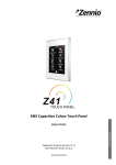
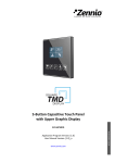
In figure 1.2, the element outline of ZAS is shown.
ZENNiO AVANCE Y TECNOLOGÍA
vwww.zennio.com
5
1.- KNX connector
2.- Temperature sensor
3.- Programming button
4.- Programming LED
5.- Inputs (A/D)
10
6 - Magnet
7.- Touch box
8 - Display
9.- IR receiver
10. Central touch panel area
Figure 1.2. ZAS Element scheme
The programming button (3) is used to set ZAS into the programming mode, by means of a short
push (the programming LED lights in red).
Note: If this button is held while plugging the device into the KNX bus, ZAS will go into secure
mode. The LED blinks in red.
Apart from the programming button(3), and particularly when it turns to be inaccessible, it will be
possible to enter the programming mode from the touch interface itself. In the factory default state,
after being connected to the KNX bus and prior to any type of download, the device will show a
certain interface, with almost no functionality at all, which, however, will commute between pages
“1” and “C” (Configuration) by pressing the “Menu” button (upper left button). Under page “C”,
pressing button number 5 (labelled with the text “Prog. LED” in the screen) will be totally equivalent
to pressing the programming button (3).
Figura 1.3. Screens “1” and “C” in the factory state
ZENNiO AVANCE Y TECNOLOGÍA
vwww.zennio.com
6
Once the download of the application program finishes, it is necessary to calibrate ZAS. The touch
calibration is carried out pressing buttons 1, 2, 7 and 8, in this order (the sequence is shown in
Figure 1.3). The Display screen will indicate the button to be pressed each time (only if a text string
associated to this process has been previously configured in ETS, under "General Labels". See
section 3.2).
Figure 1.3. Calibration sequence
To obtain more detailed information about the technical features of ZAS, as well as security and
installation information, please read the controller Datasheet, included in the original package of the
device and also available at: http://www.zennio.com.
ZENNiO AVANCE Y TECNOLOGÍA
vwww.zennio.com
7
2. CONFIGURATION
2.1. ROLL-ZAS APPLICATION
The Roll-ZAS application allows controlling a series of functionalities in a domotic installation
in a simple and intuitive way.
There are several parameters that refer to the general functionality of the controller, such as:
luminosity, touch panel locking, initial update, internal sensor, contrast, buzzer sound, presence
simulation, etc.
Pages
The information shown in the Display is divided into pages. It is possible to enable and
configure up to a total of 4 different button pages (Page 1-4), as well as the specific pages
Configuration, Security, Indicators and Screensaver. All of them are explained in detail in
section 3.3 Pages of this manual.
The access and navigation through the configured pages is explained in section 2.3.
Inputs
ZAS incorporates 2 opto-coupled inputs each of which may be individually configured as a
switch/sensor, a temperature probe or a movement detector. Depending on the selected
configuration, it is necessary to connect different external elements to the ZAS inputs: push
buttons or switches, temperature probes (like Zennio ZN1AC-NTC68) or movement sensors
(Zennio ZN1IO-DETECT).
Thermostats
ZAS allows enabling and configuring in an independent manner up to 2 thermostats, with the
"Building" functionality. How they work and the ETS configuration of this kind of thermostat is
detailed in the specific documentation "Zennio Building Thermostat", available at:
http://www.zennio.com.
ZENNiO AVANCE Y TECNOLOGÍA
vwww.zennio.com
8
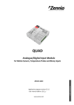
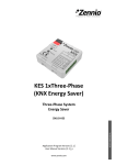
2.2. TOUCH AREA
ZAS incorporates 12 touch buttons for controlling all its functionality. Moreover, this is
complemented by the central area of the touch panel, which can also be used as a binary control.
See figure 2.1.
Touch Area
Figure 2.1. Touch Area
The first row of the touch panel consists of the following buttons:
Menu button: to navigate through the different pages of ZAS (only if this option is enabled
by parameter; see section 3.3).
Arrow buttons: to navigate through the different pages of ZAS (only if this option is
enabled by parameter; see section 3.3). Moreover, with the arrow buttons it is possible to
increase/decrease, one by one, the values of contrast, illumination and time of the Display
from the Configuration page, as well as establishing times for the timers (in the case of the
buttons configured with such purpose; see section 3.3.1).
OK Button: button to confirm and to select the desired option.
Under this first row, there are 8 more buttons, distributed into 4 rows of two buttons each. They can
be configured through ETS to operate either independently or in pairs, implementing joint functions.
They are direct-action buttons, i.e., they will carry out the parameterized action every time they are
pressed. The executed action will depend on the parameterization for the buttons in every enabled
page.
ZENNiO AVANCE Y TECNOLOGÍA
vwww.zennio.com
9
Each button contains a central LED that lights on during the time the button is kept pressed, thus
making it clear that the key press has been detected. The illumination status of the LED can be
customized, choosing between a normal illumination or dependant on the associated
communication object status. (See section 3.3.1 for further information). No LED will on in the case
of the central binary control of the touch panel.
ZAS will emit a soft beep every time a control in the touch area is pressed, unless the buzzer has
been disabled through the corresponding object.
2.3. PAGE NAVIGATION
The Roll-ZAS application has an intuitive user interface that allows, through the use of
pages, knowing at any time the chosen functionality for every button of a page.
Figure 2.2 shows how the pages are represented in the Display.
Header
Buttons
Figure 2.2. Example of page representation in the Display
Header
In the left side of the header a name (configured by parameter. See section 3.3.1) will be
shown, which identifies the current page (“ROOM 2”, in the above sample picture).
In the right side a navigation scheme is shown, composed by the sequence of numbers and
letters "i 1234 C S":
"i" refers to the Indicators page.
"1 2 3 4" refer to the pages where the direct-action controls are.
"C" refers to the Configuration page.
"S" refers to the Security page.
ZENNiO AVANCE Y TECNOLOGÍA
vwww.zennio.com
10
To have any of these letters or numbers shown in the navigation scheme of the header, it is
necessary that its referenced page has been previously enabled in ETS (see section 3.3).
Note: Take into account that Page 1 is always enabled by default and that this cannot be
modified, so number 1 will always appear here.
Thanks to the navigation scheme, it is possible to identify the current working page, since
the corresponding letter or number is highlighted.
Moreover, it is possible to know the security level required to access every enabled page.
Symbol ( ) indicates that the corresponding page has a security level of “1”, whereas symbol
(
) indicates level “2” of security. See section 3.3.3 for further information about security in
pages.
Buttons
The rest of the elements shown in the Display represent an outline of the 8 buttons of the
touch panel.
Since each of them will have an associated text (configurable by parameter) the functionality
of every enabled button can be intuitively identified.
Moreover, to identify which button has been pressed, the corresponding icon will be drawn
with the colour inverted (for example, in Figure 2.2, the button that is being pressed is the
second one from the right column).
Navigation through the enabled pages is performed by short-pressing the Menu button and/or the
Arrow buttons of the touch panel (only if the option "Page Navigation" has been enabled, for every
button, through the corresponding ETS parameter. See section 3.3). A short press on the Menu
button will scroll through the enabled pages, in this order: 1 2 3 4 Configuration
Security Indicators 1 2 …
A long press on this button will jump to the indicators page (or to page 1, if the indicators page has
not been enabled), no matter which the current page is.
If “Page navigation" is enabled for the Arrow buttons, a short press over the arrow in the right (“up”
arrow), will change to the page next to the current one (rightward), while a short press over the
arrow in the left (“down” arrow), will change to the page next to the current one, leftward. Using
these buttons permits, for instance, changing from page 3 to page 2 by a single press of the “up”
ZENNiO AVANCE Y TECNOLOGÍA
vwww.zennio.com
11
arrow, thus avoiding carrying out repeated presses over the entire sequence. A long press over any
arrow button does not imply a shifting.
After a period without navigating through the panel or pressing the touch, the Screensaver is
shown (if configured). This is a special ZAS page, which will appear after an inactivity period,
configured by parameter, and where the current time, the temperature of the room or both values
will be shown, alternately. (See section 3.3.5 for further information).
Note: Take into account that, after a KNX bus failure, the page that will be shown is Page 1, no
matter which the active page was before the failure. Moreover, if the active page is other than 1,
after 45 seconds of inactivity ZAS will automatically switch to page 1 (only if the screensaver has not
been enabled or has not been triggered yet).
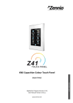
2.4. ZAS IR CONTROL
An (optional) remote control is available for ZAS, allowing the control of the functions as if
the touch panel were being actually short or long pressed. Short and long-presses are indeed
distinguished.
Moreover, the remote includes a series of buttons that directly activate some special functions such
as scenes, special climate modes (Comfort, Standby and Economy) or the sending of 1-bit objects.
Action buttons
Scenes
Special functions
Climate control
Display
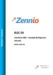
Figure 2.3. ZAS remote control
As shown by Figure 2.3, the first button row of the IR remote matches the first button row of ZAS
itself, both regarding position and functionality. The Menu, Arrows and OK keys can be found.
Functions in the external lateral columns match those of the touch panel in the device.
ZENNiO AVANCE Y TECNOLOGÍA
vwww.zennio.com
12
Besides the described buttons, which have their equivalent buttons in the touch panel, the remote
control contains the following keys for directly activating special functions:
Buttons “S1” to “S6”: to execute the scenes (from 1 to 6) that have been enabled in
section Scenes, in the "Remote" window in ETS (see section 3.2). From the remote control,
scenes can only be run, not saved.
Buttons “F1” and “F2”: they allow sending 1-bit values (“0”, “1” and alternating “0s” and
“1s”) according to the ETS parameterization.
Buttons “Comfort”, “Standby” and “Economy”: they allow directly setting the special
climate mode: Comfort, Standby and Economy. It is necessary that these modes have been
implemented in ETS in order to active them from the remote control, independently or
associated to one of the two thermostats of Roll-ZAS.
Button “Switch off”: a short press turns the ZAS display back light off. A later press on
the display or on a key of the remote control will re-activate the configured luminosity level of
the device.
When pressing a key of the remote control, besides executing the corresponding function, the
associated LED in the touch panel will light on.
Note: it is not possible to use the remote control to emulate a press on the central binary control of
the touch panel.
ZENNiO AVANCE Y TECNOLOGÍA
vwww.zennio.com
13
3. ETS PARAMETERIZATION
To begin with the parameterization of the ZAS controller it is necessary, once the ETS
program has been opened, to import the database of the product (of the Roll-ZAS application
program).
Next, the device should be added to the project where desired. And then, one right-click on the
device will permit selecting "Edit parameters", in order to start the configuration.
In the following sections there is a detailed explanation about each of the different functionalities of
MAXinBOX 16 in ETS.
3.1. DEFAULT CONFIGURATION
This section shows the default parameterization the device starts with.
Figure 3.1. Default topology
In figure 3.1 it is possible to see the communication objects available by default: "[General] Time",
for showing the current time; scenes objects "[General] Scene: receive" and "[General] Scene:
send"; and object "[General] Buzzer enabling", responsible for enabling/disabling the controller´s
buzzer.
When entering for the first time the parameter edition of Roll-ZAS, the following window will be
shown:
ZENNiO AVANCE Y TECNOLOGÍA
vwww.zennio.com
14
Figure 3.2. Configuration screen by default
As seen in figure 3.2, the configuration screen contains the following main windows:
General: destined to enable and configure the basic functionalities of the controller and
the remote control.
Pages: destined to enable and configure each available page individually, as well as the
way to navigate through them and to configure the screensaver configuration.
Inputs: destined to enable and configure each input of the controller individually.
Thermostats: destined to enable and configure each thermostat of the controller
individually.
Presence simulation: destined to enable the presence simulation and to configure its
parameters.
In the following sections, all the aforementioned windows are explained in detail.
3.2. GENERAL
The General window allows enabling and configuring the basic functionalities of the
controller and the remote control.
The basic functions that can be configured in section General are the following:
ZENNiO AVANCE Y TECNOLOGÍA
vwww.zennio.com
15
General labels. Text strings that will be shown on the "scene saved" event, as well as
text strings that will be shown through the screen calibration process. The texts parameterized
by default are "Saved", "Calibrate" and "Press".
Figure 3.3. General labels.
Luminosity. This functionality permits a customized configuration of the luminosity when
in normal operation and when in screensaver mode, or keeping the default levels (these
values are: Normal luminosity = 10 and Screensaver luminosity = 7). To customize this
luminosity level, the following options appear:
Figure 3.4. Luminosity options
Level while normal operation: a value between 5 (minimum luminosity) and 10
(maximum luminosity).
Level while screensaver: a value between 3 (minimum luminosity) and 10
(maximum luminosity).
Two more parameters apply here, to configure two special luminosity levels:
Special level 1/Special level 2 [Object]: after enabling any of them, it will be
possible to configure the desired luminosity level (from 1 to 10). Moreover, it will be
ZENNiO AVANCE Y TECNOLOGÍA
vwww.zennio.com
16
possible to set a method for enabling each special level, which can be "1-bit object" (the
1-bit communication objects "[General] Display lighting 1 or 2" will activate special levels 1
or 2 when they receive, respectively, the values "1" or "0", as configured) or "Scene",
which activates levels 1 or 2 when the parameterized scene value is received through the
object "[General] Scene: receive".
LED blink object: when enabling this parameter, a new 1-bit communication object
is displayed: "[General] LED Blink", which will light up (during the time specified in the
parameter "Blink time", in the range 1-20 seconds) every ZAS button containing a LED
whenever the value "1" is received.
This option may be useful when connecting ZAS to a presence detector, so that when it
detects movement in the room to be controlled, it sends the value "1" through a
communication object that must be linked to the same group address as the object
"[General] LED Blink". In that moment, the LEDs of the ZAS buttons will light up during
the parameterized time, thus allowing locating, even in the darkness, where the ZAS
buttons are.
Touch locking. This function allows locking and unlocking the ZAS buttons. The
following fields can be configured:
Locking method: ZAS buttons may be locked by means of: the 1-bit object
"[General] Touch lock" (with value “0” or “1”, configurable), scenes (configurable scene
number 1-64), or automatic locking (establishing the time to pass between the last key
press and the automatic locking –time to lock–, in seconds).
ZENNiO AVANCE Y TECNOLOGÍA
vwww.zennio.com
17
Unlocking method: ZAS buttons may be unlocked by means of: the 1-bit object
"[General] Touch unlock" (with value “0” or “1”, configurable), via scenes (configurable
scene number 1-64), or pressing the ZAS touch panel, which also allows sending a
welcome object (1-bit object or scene), through the objects “[General] Welcome object”
and “[General] Scene: receive”, respectively.
Note: do not confuse the possibility to send a 1-bit value through the “[General] Welcome
object” on the unlocking event (i.e., pressing whatever part of the touch panel –including
the central area– while locked) with the possibility of using the central area of the touch
panel as a binary control (i.e., for sending the value “0” or “1” through the object
“[General] Central button”) while unlocked.
Lock IR as well?: option to lock the remote control at the same time as the touch
panel ("Yes"). In this case, presses over the remote will not be taken into account until
ZAS is unlocked.
Figure 3.5. Touch locking
Initial update. This functionality is intended for updating the value of the general
indicators (if they were enabled by parameter) as well as the values of the 1-bit objects
associated to the buttons, and the object "[General] Time", on bus power recovery after a
power failure. Moreover, a delay after the power recovery is possible before the request for
the initial values is sent (to get an immediate sending, set 0 in this field).
Note: If this function is not enabled, the values prior to the bus power failure will be kept.
Remote control. When enabling this option in the general menu, the operation of the
remote control will be activated, to remotely control ZAS.
ZENNiO AVANCE Y TECNOLOGÍA
vwww.zennio.com
18
Figure 3.6. Remote control
The following parameters may be configured:
Action buttons only for Page 1?: this parameter sets if the action buttons of the
remote control (see Figure 2.3) will only control the configuration established for page 1
(option "Yes") or if they will simulate the behaviour of the buttons of all the configured
pages (1-4), with option "No".
The exclusive control of the buttons of page 1 implies that every press over the remote’s
Menu or Arrow buttons will not be taken into account (navigation through the other pages
from the remote control is not possible, but it is by pressing the same buttons in the touch
panel). Presses over the other action buttons will provoke an automatic switch to page 1
and the corresponding action will be executed, according to the pressed button.
If the action buttons of the remote do not only control page 1, presses over them will carry
out different actions, according to the currently shown page and the configuration
parameterized for every button.
Special function 1 (F1): configurable for sending the values "1", "0" or switching
between them when button F1 from the remote control is pressed. A new 1-bit
communication object will appear: "[IR] F1".
Special Function (F2): same behaviour as F1, but in this case, when pressing
button F2 in the remote control, the 1-bit object "[IR] F2" will be enabled.
ZENNiO AVANCE Y TECNOLOGÍA
vwww.zennio.com
19
Scene 1-6 (S1-S6): these parameters allow establishing the scene number (1-64)
that will be sent to the KNX bus (through the object "[General] Scene: send" when
pressing the scene buttons in the remote control (Figure 2.3).
HVAC mode buttons: this parameter allows selecting the type of control that the
climate buttons of the remote control (see Figure 2.3) will carry out: direct control of the
special modes of thermostats 1 and 2 of Roll-ZAS, being possible for example to
simulate, with every press, the arrival of a new special mode to the corresponding object
("[Tx] Special mode"), without linking any group address.
On the other side, it is also possible to configure these buttons to carry out the control of
the special modes of a remote thermostat. For this purpose, a new 1-byte communication
object is enabled: "[IR] Special mode", which will send to the remote thermostat the value
of the button pressed ("1" for Comfort, "2" for Standby and "3" for Economy).
IR locking: locking the remote control can be configured from the "Touch locking"
screen already mentioned, since it can only be locked with the touch panel altogether.
Internal Temp. Sensor. ZAS includes a built-in temperature sensor with an associated 2byte communication object ("[Internal Sensor] Current Temperature"), which appears when
the internal sensor function is enabled in the General parameterization window.
Figure 3.7. Internal Temperature Sensor
Here it is possible to configure the following features:
Temperature sensor calibration: this option allows calibrating (in tenths of a
degree) a possible deviation between the measurement made by the sensor and the real
temperature of the room.
Temperature sending period: this is the period time (in tens of a second) for
cyclically sending to the KNX bus the current temperature measure, through the
ZENNiO AVANCE Y TECNOLOGÍA
vwww.zennio.com
20
communication object "[Internal Sensor] Current Temperature". The value 0 indicates that
the periodical sending is disabled.
Send with a temperature change: ZAS can also send to the KNX bus the current
temperature value when it detects, compared to the previous reading, a change (increase
or decrease) of at least the amount of degrees specified in this parameter (from 0 to 200
tenths of a degree). To disable this sending, just set a 0 for this field.
Temperature protection: permits enabling overheating, overcooling or both
protections. Depending on the selected protection, one or two communication objects will
be enabled: "[Internal Sensor] Overheating" and "[Internal Sensor] Overcooling", which
will indicate (with the value "1") if the corresponding limit has been exceeded. It is
necessary to define the overheating or the overcooling temperature (or both), in degrees,
as well as a hysteresis value (tenths of a degree).
Contrast level: the initial contrast level of the display can be set (0-20). This value can be
changed later, if the contrast function of the configuration page is activated.
Buzzer object. Associated to this parameter is the 1-bit communication object "[General]
Buzzer", which will make ZAS emit a beep when receiving the value "1". The value "0" does
not cause any action.
Note: Take into account that for this beep to be emitted, the buzzer must be enabled
("[General] Buzzer enabling"=1).
3.3. PAGES
From this section it is possible to enable and configure individually the pages to be
implemented in ZAS.
ZENNiO AVANCE Y TECNOLOGÍA
vwww.zennio.com
21
Figure 3.8. Page configuration window
In the first place, two parameters are provided to configure which buttons will be destined to
navigate through the enabled pages: Menu or Arrow buttons. To obtain more detailed information
about navigating through pages, please consult section 2.3 of this manual.
Parameter "Pair button behaviour" also appears here, permitting the selection of the function of
the pair buttons configured in the pages, being possible to choose whether pressing the right button
will send an ON/increase order while a pressing on the left button sends an OFF/decrease order, or
the opposite.
The pages to be enabled and configured are: Pages 1-4, Configuration page, Security page,
Indicators page and Screensaver. All of them are explained in detail in the following sections.
Finally, parameter “Use the central area of the touch as a binary button” is shown, making it
possible to enable or disable this functionality. If “yes” is selected a second parameter, “Action”, will
come up. This Action will determine whether one “0”, one “1” or an alternating value (“Switch 0/1”)
will be sent as a response when the user presses over this central area. The sendings will be made
through the specific object “[General] Central button”.
ZENNiO AVANCE Y TECNOLOGÍA
vwww.zennio.com
22
3.3.1. PAGES 1-4
In every enabled page, up to 8 individual buttons or up to 4 pair buttons can be enabled.
According to the selected configuration, each button can have several functionalities, which are
explained in detail below.
Note: The configuration options and screenshots shown below refer to Page 1, but they are exactly
the same for the rest of the pages (2-4).
Figure 3.9. Page 1. Configuration
First of all the Header parameter is shown, where it is possible to establish an identifying text string
(up to a total of 10 characters) for every page, which will be shown in the left upper corner of the
Display (Figure 2.2).
Next, it is possible to establish the desired configuration, individual or in pairs, for each of the 8
buttons that can be enabled in every page. The different options for every configuration are
explained next.
ZENNiO AVANCE Y TECNOLOGÍA
vwww.zennio.com
23
a) PAIR BUTTONS
The options for pair buttons are the following:
Note: For all the cases listed below it is possible to select, through the parameter Icon, what pair of
icons should be drawn, pixel by pixel, over the representation of each button in the display. To
check the list of available icons, please consult the Annex I of this manual.
Switch: enables the 1-bit communication object "[Px][Byz] Binary control" for each pair,
which will send value "0" or "1", depending on the button that is pressed. This option allows
setting a name for the functionality associated to the buttons, and a text message for actions
Switch On and Switch Off.
Parameter LED lighting indicates if the pair of buttons will have a Regular lighting (while a
button is being pressed, the corresponding LED will stay on for a few instants), a Statedependent lighting (depending on the current value of object "[Px][Byz] Binary control", the left
or the right LED will remain on indefinitely) or a State-dependent (both LEDs) lighting (both
LEDs will stay on or off simultaneously, depending on the value of the object).
Dimmer: 3 communication objects are enabled: "[Px][Byz] Light On/Off", a 1-bit object to
switch on/off a source of light; "[Px][Byz] Light dimming", a 4-bit object for dimming the
luminosity, and "[Px][Byz] Light indicator", a 1-byte object to indicate, in percentage, the
luminosity status (0%=Off, 100%=On). In the Display, the status sent by the dimmer will be
shown, as a percentage between both buttons.
Light dimming is carried out as follows:
Off/Decrease button: a short press switches the light off ("[Px][Byz] Light On/Off"=0).
A long press sends an order to decrease the luminosity level, according to the dimming
step configured, which is followed by a stop order (0x00 in this case) as soon as the
button is released.
On/Increase button: a short press switches the light on ("[Px][Byz] Light On/Off"=1). A
long press sends an order to increase the luminosity level, according to the dimming step
configured, which is followed by a stop order (0x08 in this case) as soon as the button is
released.
It is possible to customize the name of the associated functionality and to select the desired
Dimming step, in percentage (see Table 3.1).
ZENNiO AVANCE Y TECNOLOGÍA
vwww.zennio.com
24
Parameter LED lighting indicates if the pair of buttons will have a Regular lighting (while a
button is being pressed, the corresponding LED will stay on for a few instants), a Statedependent lighting (depending on the current value of object "[Px][Byz] Light dimming", the left
or the right LED will remain on indefinitely) or a State-dependent (both LEDs) lighting (both
LEDs will stay on or off simultaneously, depending on the value of the object).
Dimming step
(1) 100%
(2) 50%
(3) 25%
(4) 12.5%
(5) 6.25%
(6) 3.1%
(7) 1.5%
Necessary pulsations for a complete
regulation (0-100%)
1
2
4
8
16
32
64
Table 3.1. Dimming step
Shutter: it allows controlling the movement of shutters by means of two binary objects:
"[Px][Byz] Move shutter" ("0"=Up and "1"=Down) and "[Px][Byz] Stop shutter" and one 1-byte
object "[Px][Byz] Shutter position", which sets the position of the shutter, in percentage, at any
time (0%=Top, 100%=Bottom). In the Display, between both buttons, the status sent from the
corresponding shutter controller will be shown as a percentage.
Shutter controlling is carried out as follows:
Decrease button: a long press moves the shutter down, while a short press stops the
shutter. The value "1" is sent through the object "[Px][Byz] Stop shutter".
Increase button: a long press moves the shutter up, while a short press stops the
shutter. The value "0" is sent through the object "[Px][Byz] Stop shutter".
Scaling: allows sending a percentage value through the object "[Px][Byz] Scaling"
associated to the particular pair of buttons. Lower and upper limits must be configured (values
between 0% and 100%). The behaviour of this type of buttons is as follows:
Decrease button: a short press decreases the percentage value one by one, while a
long press decreases the value 10 by 10.
ZENNiO AVANCE Y TECNOLOGÍA
vwww.zennio.com
25
Increase button: a short press increases the percentage value one by one, while a
long press increases the value 10 by 10.
Counter: allows sending an integer value through the object "[Px][Byz] 1-byte counter"
associated to the particular pair of buttons. Lower and upper limits must be configured (values
between 0 and 255). The behaviour of this type of buttons is as follows:
Decrease button: a short press decreases the counter value one by one, while a long
press decreases the value 10 by 10.
Increase button: a short press increases the counter value one by one, while a long
press increases the value 10 by 10.
Enumeration: allows sending a numeric value (0-255) via the object "[Px][Byz] Enum
control" corresponding to the particular pair of buttons. Up to 6 discrete values can be
configured for the enumeration (Value 1-Value 6). It is necessary to introduce a label (String
1-String 6) for each value in order to enable them in the enumeration menu. Pressing the right
or left buttons will make the different labels alternate in the display, sending to the bus the
numeric value associated to the final label. The first press will always show the current value
of the control. A continuous press over any of the two buttons of the couple will send the
current value to the bus.
Temperature: allows controlling a temperature value (between -20ºC and 95ºC).
Associated to this functionality is the 2-byte communication object "[Px][Byz] Temperature
control". Lower and upper limits must be configured (values between -20 and 95ºC). The
behaviour of this type of buttons is the following:
Decrease button: a short press decreases the temperature by 0.5ºC. A long press
decreases the temperature value by 1ºC.
Increase button: a short press increases the temperature by 0.5ºC. A long press
increases the temperature value by 1ºC.
Switch control + Indicator: Enables one 1-bit communication object for each pair,
"[Px][Byz] Binary control", which will send the value "0" or "1", depending on the button that is
pressed. Moreover, a numerical indicator may be configured, whose value will be shown in the
Display, next to the parameterized name for the pair of buttons, in parenthesis. This indicator
can be of the following types:
ZENNiO AVANCE Y TECNOLOGÍA
vwww.zennio.com
26
1-byte unsigned integer. Enables the 1-byte object "[Px][Byz] 1-byte indicator",
which will receive the value (0-255) to be represented in the Display every time a button
of the pair is pressed.
Scaling. Enables the 1-byte object "[Px][Byz] Scaling indicator", which will receive
the value (0-100%) to be represented in the Display every time a button of the pair is
pressed.
2-byte unsigned integer. Enables the 2-byte object "[Px][Byz] 2-byte indicator",
which will receive the value (0-65535) to be represented in the Display every time a
button of the pair is pressed.
Temperature. Enables the 1-byte object "[Px][Byz] Temperature indicator", which will
receive the value (-20 and 95ºC) to be represented in the Display every time a button of
the pair is pressed.
Multimedia control: (Only available for pair buttons in Page 4).
The 1-bit communication object "[P4][Byz] Binary control" is enabled, which will be set to value
"0" or "1", depending on the button that is pressed. Moreover, associated to the multimedia
control is the 14-byte object "[P4][Byz] String indicator", through which a text string of up to 14
characters is received, which will be represented in the Display, in the middle of the two
buttons of the pair.
Take into account: After a KNX bus failure, the values received through the 14-byte object
will be deleted. It is necessary to wait 15-20 seconds before accessing page 4 so that this
process is complete and there are no remaining residual characters.
ZENNiO AVANCE Y TECNOLOGÍA
vwww.zennio.com
27
b) INDIVIDUAL BUTTONS
The options for individual action buttons are the following:
Note: For all the cases listed below it is possible to set, through the Icon parameter, the icon that
will be drawn, pixel by pixel, over the representation of each individual button in the display. To
check the list of available icons, please consult Annex I of this manual.
1 bit: it allows sending the values “0” and “1”, or switching between them. This option
allows setting a name for the function, associated to the button, and a text message for
actions Switch On and Switch Off.
Parameter LED lighting indicates if the button will have a Regular lighting (while a button is
being pressed, the corresponding LED will stay on for a few instants) or a State-dependent
lighting (depending on the current value of the related object; the button LED will light while
the object status is “1” and will remain switched off when the object status is “0”).
1-bit (Hold & Release): under this mode, the KNX bus will be sent a binary value ("0" or
"1") through the 1-bit object "[Px][Byz] Binary control: Hold" while the corresponding button is
held, and the same value (or another one) when the button is released, via the object
"[Px][Byz] Binary control: Release".
Scene: this allows the configuration of the button for running a scene or running and
saving a scene. The value of the configured scene (1-64) will be sent through the "[General]
Scene: send" object, causing the execution of the corresponding scene. This will happen after
a short press over the button. If scene saving was also enabled, a long press over the button
(at least 3 seconds), will cause that the current scene is saved.
1-byte constant: it allows sending a 1-byte fixed value when the button is pressed, via
the object "[Px][By] 1-byte value". The range is 0 to 255.
2-byte constant (unsigned integer): it allows sending a 2-byte fixed unsigned integer
value when the button is pressed, via the object "[Px][By] 2-byte value (unsigned int)". The
range is 0 to 65535.
2-byte constant (float): it allows sending a 2-byte fixed value when the button is
pressed, via the object "[Px][By] 2-byte value (float)". The range is 0 to 120.0.
ZENNiO AVANCE Y TECNOLOGÍA
vwww.zennio.com
28
Dimmer: three communication objects are enabled: "[Px][By] Light On/Off", a 1-bit object
to switch on/off a source of light; "[Px][By] Light dimming", a 4-bit object for luminosity
dimming; and "[Px][By] Light indicator", a 1-byte object to indicate, as a percentage, the
luminosity status (0%=Off, 100%=On). In the Display, next to the button, the dimmer value
received from the dimmer controlled by ZAS will be shown, as a percentage.
Light dimming is carried out the same way as described for the pair buttons.
It is possible to customize a name for the associated functionality and to select the desired
Dimming step, in percentage (see Table 3.1).
Parameter LED lighting indicates if the button will have a Regular lighting (while a button is
being pressed, the corresponding LED will stay on for a few instants) or a State-dependent
lighting (depending on the current value of the related object; the button LED will light while
the object status is “1” and will remain switched off when the object status is “0”). Object
"[Px][By] Light On/Off" must be linked to the status object of the light actuator so that the LED
lighting status is always up to date.
Timer: this functionality allows sending to the KNX bus a binary value ("1" or "0") or a
scene number at a certain time, as a single sending (one-time Execution), as a periodic
sending or after a parameterized time. The sending of the binary value is carried out through
the object "[Px][By] Timed switch control". The sending of the scene, through the general
scene sending object.
It is possible to configure the timer type by selecting one of the following:
One-time Execution. The parameterized value ("0", "1" or Scene) is sent once
through the corresponding object at a certain time.
Periodic Execution. The parameterized value ("0", "1" or Scene) is sent through the
corresponding object at a certain time, everyday.
Countdown. The parameterized value ("0", "1" or Scene) is sent through the
corresponding object once elapsed the parameterized time.
For these values to be sent at the established time, it is necessary that the timer is enabled.
This may be achieved by performing a short press over the corresponding button (each press
switches the status: disabled/enabled) or by sending the value "1" through the object "[Px][By]
Timer enable", which is deployed for this purpose (only for the one-time execution and the
ZENNiO AVANCE Y TECNOLOGÍA
vwww.zennio.com
29
periodic execution timers). If the timer is enabled, this is made evident in the Display by an
intermittent blink of the timer information – the name of the button and the parameterized time.
Besides, the LED of the button will stay ON. In the case of a countdown, the same applies,
although the time is preceded by the "-" sign, thus indicating that the time is a decreasing
value. If the timer is disabled, just the name of the button is shown and the associated LED is
off.
It is necessary to set the particular time at which the parameterized value will be sent to the
KNX bus (for the countdown, the time to be elapsed before sending that value). This action is
performed directly from the Display, by long-pressing the corresponding button. In this
configuration mode, a digital clock is shown (with the hh:mm format) where to configure the
time at which the value will be sent to the bus. To modify the hour and the minutes, the arrow
buttons should be used. To set the minutes and/or to confirm the programmed time, just shortpress the OK button or the timer button in the touch panel. For the countdown, time setting is
carried out in the same way, but it will be possible to access the programming mode by a long
or a short press.
3.3.2. CONFIGURATION PAGE
From this ETS window it is possible to enable and to assign a name to the adjustable
parameters of ZAS. The enabled parameters will be shown in the Display, inside the Configuration
page, making it possible to adjust their values in Execution time, when desired.
Figure 3.10. Configuration parameters
ZENNiO AVANCE Y TECNOLOGÍA
vwww.zennio.com
30
It is possible to set a header, text string of up to 10 characters that identifies the Configuration page
and that will be shown in the left upper side of the display when accessing that page.
The adjustable parameters of ZAS are the following:
Contrast: to adjust the contrast level of the ZAS display (value between 0 and 20). To
modify this level, just press the button corresponding to the Contrast in the touch panel (the
first one on the left). The current contrast level is then shown; to increase it, just press the up
arrow button and to decrease it, the down arrow button.
Light to adjust the luminosity level of the ZAS display (value between 1 and 10). To
modify this level, just press the button corresponding to the Luminosity in the touch panel (the
first one on the right). The current luminosity level is then shown; to increase it, just press the
up arrow button and to decrease it, the down arrow button.
Time: to set the clock time of the controller. Format is "hh:mm". To modify this, just press
the button corresponding to Time in the touch panel (the second one on the left). The current
time will be shown; the first thing to be modified is the hour, by means of the Arrow buttons.
Then, via the OK button or the Hour button itself, the focus goes to the Minutes, that can be
adjusted with the Arrow buttons. To confirm the new hour value, just press the OK button or
the Time button.
Note: On bus power losses and depending on length, a delay in the internal time of the device
may happen. This must be kept in mind and corrected once the power supply is restored.
Calibration: when pressing this button, ZAS goes into the calibration page. See the
calibration sequence in figure 1.3. A re-calibration may be necessary when the initial
calibration has not been carried out properly after downloading the application so presses
cannot be done in the centre of the button.
Programming LED: when programming the physical address of the device, it is possible
to enter the programming mode directly by short-pressing this button. This feature avoids
having to access the rear side of the panel to physically push the “Programming Button”.
While the programming LED is active, the LED associated to this button will be ON. To leave
the programming mode, just short-press this button again (the programming LED and the
button LED will be switched off).
Reset: a long press of at least of 3 seconds will be required on this button to reset ZAS.
All the stored statuses will be reset to the default values.
ZENNiO AVANCE Y TECNOLOGÍA
vwww.zennio.com
31
3.3.3. SECURITY PAGE
The security page allows configuring access restrictions to the different enabled pages, as
well as modifying the security password (or passwords).
Figure 3.11. Security page
It is possible to set a header, text string of up to 10 characters that identifies the Security page and
that will be shown in the left upper area of the display when accessing that page.
The first parameter to be configured is the number of the security levels to perform, being possible
to select one level (value by default) or two levels.
In case of selecting two levels, two parameterizable sections will be shown, Default Password
(Level 1) and Default Password (Level 2), where to establish the desired password for each
security level. Default passwords are "1234" for Level 1 and "5678", for Level 2.
ZENNiO AVANCE Y TECNOLOGÍA
vwww.zennio.com
32
Take into account: Level 2 is the maximum security level, so Level 2 Password has a higher
priority than Level 1 Password. This means that it will be possible to access pages protected with
Level 1 by using Level 2 Password, but not the opposite.
Next, it is necessary to set the desired protection level for every page (pages 1-4 and Configuration
page): Not Restricted; Restricted: Level 1; or Restricted: Level 2. The protection level is associated
to the page itself, not to the buttons of the page. The Security page is always protected with the
maximum security level, according to the number of security levels configured.
Last, it is possible to configure several Labels or text strings that will be shown when setting or
modifying the password from the touch panel, in execution time.
The configured security level may be modified in Execution time through the Security page in the
Display (see Figure 3.12).
Figure 3.12. Security page (Display)
Buttons 1-4 allow here to modify the security level of pages 1-4, respectively, while button 5 is
intended to modify the security level of the Configuration page. A short press over these buttons will
change the security level of the corresponding page, in this order: No Security ( ) Level 1( )
Level 2 (
) No Security ( )…
Buttons 7 and 8 allow changing the configured password in ETS for Level 1 and 2, respectively.
Once the password is properly typed, it will be possible to freely navigate during 60 seconds
through the ZAS pages with a security level equal or lower than the password set. When this time
expires, ZAS will ask for the password if the user tries to act on a page protected with whatever
security level. If the typed password is wrong, it will not be possible to type it again until 3 seconds
later, for security reasons.
ZENNiO AVANCE Y TECNOLOGÍA
vwww.zennio.com
33
3.3.4. INDICATORS PAGE
From this window it is possible to enable and configure up to 6 general indicators of different
types.
Figure 3.13. Indicators page
Binary: shows in the Display a text configured by parameter, according to the value ("0"
or "1") received by the "[Ind x] Binary indicator" object.
Counter: shows in the Display the value received by the "[Ind x] 1-byte indicator" object.
Scaling: shows in the Display the value received by the "[Ind x] Scaling indicator" object.
Enumeration: allows the definition of up to 6 discrete values with their corresponding
labels (texts configurable by parameter). According to the value received by the "[Ind x] Enum
indicator" object, one string or another will be shown in the Display.
Float: shows the value received by the "[Ind x] Float indicator" object, specifying the units
(text configurable by parameter).
The name of every indicator can be set (name to be shown in the display).
ZENNiO AVANCE Y TECNOLOGÍA
vwww.zennio.com
34
3.3.5. SCREENSAVER
The screensaver is a special page in ZAS that will be shown after a period of inactivity,
configurable by parameter.
It is possible to configure the screensaver to only show the current Time, the current Temperature
(selecting the desired measurement source: Internal temperature sensor or a external value,
received by the "[General] Screensaver temperature" object) or both (alternatively every 5
seconds).
Note: The temperature shown in the screensaver must be in the range [-20ºC, 95ºC].
The screensaver can also be disabled. In this case, after a period of inactivity greater than 45
seconds, ZAS will switch to Page 1 automatically. Moreover, the luminosity level of the Display can
be configured, being the possible options:
Always lighting: the Display remains lit without switching off after the inactivity
period.
Automatic display attenuation: the Display decreases its luminosity to level 3 after
the inactivity period.
On the other hand, parameter “Execute button action (Page 1) on screensaver exit?” lets
determining whether, while the screensaver is active, one press on the touch panel (on any of the
single buttons or on the central binary button) should simply cause the screensaver interruption or,
moreover –apart from exiting from the screensaver–, the execution of the action corresponding to
the pressed button, assuming it was pressed while Page 1 was active.
ZENNiO AVANCE Y TECNOLOGÍA
vwww.zennio.com
35
3.4. INPUTS
ZAS includes two input channels that can be configured as switches/sensors, temperature
probes or movement detectors.
Once the input is enabled, the access to the corresponding configuration window is shown in the
main menu according to the configured input type.
3.4.1. SWITCH/SENSOR
When configuring an input as a switch/sensor, it is necessary to select the actions to perform
on the arrival of one falling edge and on the arrival of one rising edge.
Figure 3.14. Input: Switch/Sensor
The available options are:
Rising edge: for selecting the value to be sent when this edge happens:
Nothing (no action is performed).
0: object "[Ix] Edge" is sent to the KNX bus with value "0".
1: object "[Ix] Edge" is sent to the KNX bus with value "1".
Switching: "0" or "1" are alternatively sent to the KNX bus.
Falling edge: for selecting the value to be sent when this edge happens. As in the above
case, Nothing, 0, 1 or Switching are permitted.
ZENNiO AVANCE Y TECNOLOGÍA
vwww.zennio.com
36
Sending of "0" Delay: specifies the time, in seconds, after which the value "0" will be
sent, once the corresponding signal has been received.
Sending of "1" Delay: specifies the time, in seconds, after which the value "1" will be
sent, once the corresponding signal has been received.
Periodical sending of "0": defines the period, in seconds, for a cyclical sending of the
value "0". Setting this to 0 disables the periodical sending.
Periodical sending of "1": defines the period, in seconds, for a cyclical sending of the
value "1". Setting this to 0 disables the periodical sending.
Lock: if "Yes" is chosen, a new 1-bit communication object, "[Ix] Lock", is deployed,
making it possible to lock and unlock the corresponding input (with one "1" or one "0",
respectively). During the time the input is locked, orders received from the KNX bus will be
ignored.
Sending statuses on bus voltage recovery: this option allows forcing an automatic
sending to the KNX bus of the status of each input after a voltage recovery, with a certain
delay (value between 0 and 255, in seconds).
3.4.2. TEMPERATURE PROBE
When configuring an input as a temperature probe, the following options are available:
Figure 3.15. Input: Temperature probe
Temperature sensor calibration: this is to re-calibrate (in tenths of a degree) the value
measured by the sensor when another sensor from the installation can be used as a
reference, thus making it possible to synchronize both measures.
ZENNiO AVANCE Y TECNOLOGÍA
vwww.zennio.com
37
Temperature sending period: this is intended to set the period (in tens of a second) for
a cyclical sending to the KNX bus of the current temperature value. Setting this to 0 indicates
that no periodical sending will take place.
Send with a temperature change: the current value of the temperature will be sent to
the KNX bus when it shows an increment or decrement (compared to the previous measure)
greater than the amount set by parameter (from 0 to 200 tenths of a degree).
Temperature protection: permits enabling overheating, overcooling or both protections.
Depending on the chosen protection, one or two communication objects will be enabled: "[Ix]
Overheating" and "[Ix] Overcooling", which will indicate (with the value "1") if the
corresponding limit has been exceeded. It is necessary to define the overheating or the
overcooling temperature (or both), in degrees, as well as a hysteresis value (tenths of a
degree).
3.4.3. MOVEMENT DETECTOR
When an input is configured as a Movement detector, up to two detection channels can be
enabled (per input).
Figure 3.16. Input: Movement detector
After enabling the available channels, the following configuration window will be shown:
ZENNiO AVANCE Y TECNOLOGÍA
vwww.zennio.com
38
Figure 3.17. Channel configuration
For further information on the behaviour and the ETS parameterization of them, please consult the
specific documentation “Motion Detector”, available at: http://www.zennio.com.
3.5. THERMOSTATS
The possibility to controlling up to 2 independent thermostats is also covered by the RollZAS application.
Figure 3.18. Thermostat 1 Configuration
ZENNiO AVANCE Y TECNOLOGÍA
vwww.zennio.com
39
To obtain theoretical information about how Zennio thermostats work, as well as information about
the ETS configuration, please consult the specific documentation "Thermostat Zennio" available at:
http://www.zennio.com.
3.6. PRESENCE SIMULATION
This function is designed to simulate presences in a building, once the devices of the KNX
installation have been correctly parameterized.
It allows randomly switching on/off some elements in the domotic installation during a period of time
set by parameter.
Figure 3.19. Presence simulation
After enabling the presence simulation in ETS, two new 1-bit communication objects will be shown:
"[Sim] Presence Simulation" and "[Sim] Simulation Channel". The first one allows activating or
deactivating the presence simulation, by sending the value "1" or "0", respectively (note that the fact
of enabling this functionality does not necessarily imply an immediate begin of the presence
simulation; it will be subject to the parameterized start and finish times). The second one is in
charge of randomly sending (i.e., at random instants between the parameterized start and the end
times, respecting in any case the parameterized minimum and maximum times for each state)
binary values ("1" or "0") to switch the devices in the KNX installation on and off, such as light
ZENNiO AVANCE Y TECNOLOGÍA
vwww.zennio.com
40
sources or shutter controllers. This object must be linked to the same group address as the
corresponding control objects that are in charge of switching the devices on and off in the
installation.
The parameters to be configured are:
Starting/Finish time: to establish the start time (hours and minutes) at which the
presence simulation begins or finishes (provided that the functionality has been enabled by a
“1” through the object "[Sim] Presence simulation").
Note: The start and the finish times must be different values; if not, the presence simulation
will not work properly.
Minimum/Maximum ON/OFF time to adjust, by parameter, the minimum and maximum
ON/OFF time for the devices in the installation.
Note: The value established for Maximum Time (both ON and OFF) must be greater than the
value established for Minimum Time. If not, anomalous situations can be expected.
ZENNiO AVANCE Y TECNOLOGÍA
vwww.zennio.com
41
ANNEX I. BUTTON ICONS
Icons for individual buttons:
Name
Default
Off
On
0
1
Minus
Plus
Down
Up
Left
Right
Stop
Play
Icon
Icons for pair buttons: they are the same as for individual buttons, but they appear
grouped in pairs. The left one will be shown on the left button of the pair, while the right one
will be on the right button.
Name
Default
Off/On
0/1
Minus/Plus
Down/Up
Left/Right
Stop/Play
ZENNiO AVANCE Y TECNOLOGÍA
Icon
vwww.zennio.com
42
ANNEX II. COMMUNICATION OBJECTS
SECTION
INDICATORS
NUMBER
SIZE
IN/OUT
VALUES
FLAGS
st
NAME
RANGE
1 TIME
RESET
DESCRIPTION
0-5
1 bit
I/O
RWU
0/1
0
Last
[Ind x] Binary indicator
1-bit generic indicator
0-5
1 byte
I/O
RWU
0-255
0
Last
[Ind x] 1-byte indicator
1-byte generic indicator
0-5
1 byte
I/O
RWU
0-100%
0
Last
[Ind x] Scaling indicator
Scaling value
0-5
1 byte
I/O
RWU
0-255
0
Last
[Ind x] Enum indicator
1-byte enumeration
0-5
2 bytes
I/O
RWU
0-6553.5
0
Last
[Ind x] Float indicator
2-byte float value
Several Functionings
Several
0/1
0-255
-20-95ºC
0-100%
0-6553.5
[P1][By] “Individual Buttons Page 1”
6-37
1 bit
1 byte
2bytes
-
[P1][Byz] “Pair Buttons Page 1”
Several Functionings
[P2][By] “Individual Buttons Page 2”
Several Functionings
[P2][Byz] “Pair Buttons Page 2”
Several Functionings
[P3][By] “Individual Buttons Page 3”
Several Functionings
[P3][Byz] “Pair Buttons Page 3”
Several Functionings
[P4][By] “Individual Buttons Page 4”
Several Functionings
[P4][Byz] “Pair Buttons Page 4”
Several Functionings
38-69
I/O
1 bit
1 byte
2bytes
I/O
1 bit
1 byte
2bytes
I/O
Several
BUTTONS
70-101
102-133
241-244
ZENNiO AVANCE Y TECNOLOGÍA
1 bit
1 byte
2bytes
4 bytes
I/O
Several
Several
0/1
0-255
-20-95ºC
0-100%
0-6553.5
0/1
0-255
-20-95ºC
0-100%
0-6553.5
0/1
0-255
-20-95ºC
0-100%
0-6553.5
-
-
-
-
-
-
vwww.zennio.com
43
SECTION
NUMBER
SIZE
IN/OUT
VALUES
FLAGS
st
NAME
RANGE
1 TIME
RESET
134
3 bytes
I/O
TRWU
-
00:00
Last
135
1 byte
I
W
0-63
Indifferent
136
1 byte
O
T
0-63
137
1 bit
I
W
138
1 bit
I
139
1 bit
I
DESCRIPTION
[General] Time
Current time
Indifferent
[General] Scene: receive
0-63 (Run Scene 1-64)
Indifferent
Indifferent
[General] Scene: send
0-63 (Run or Save Scene 1-64)
0/1
Indifferent
Indifferent
[General] Display Lighting 1
1=Light the display; 0=No action
W
0/1
Indifferent
Indifferent
[General] Display Lighting 2
1=Light the display; 0=No action
W
0/1
Indifferent
Indifferent
[General] Touch block
1=Block; 0=Nothing
0=Block; 1=Nothing
GENERAL
0=Unblock; 1=Nothing
140
1 bit
I
W
0/1
Indifferent
Indifferent
[General] Touch unblock
1=Unblock; 0=Nothing
PRESENCE
SIMULATION
141
1 bit
O
T
0/1
Indifferent
Indifferent
[General] Welcome object
1-bit generic control
142
2 bytes
O
TR
-20-95ºC
25ºC
Indifferent
[General] Screensaver temperature
Temp. In the screensaver
239
1 bit
I
W
0/1
0
Last
[General] LED Blink
1=Blink LEDs; 0=Nothing
240
1 bit
I
W
0/1
0
Last
[General] Buzzer
1=Beep; 0=Nothing
245
1 bit
I
W
0/1
1
Last
[General] Buzzer Enabling
1=Enabled; 0=Disabled
246
1 bit
O
RT
0/1
1
1
[General] Central Button
1-bit generic control
147
1 bit
I
W
0/1
0
Last
[Sim] Presence simulation
0=Disabled; 1=Enabled
148
1 bit
O
RT
0/1
Random
Random
[Sim] Simulation Channel
0=Off; 1=On
ZENNiO AVANCE Y TECNOLOGÍA
vwww.zennio.com
44
SECTION
REMOTE COTNROL
INPUTS
NUMBER
SIZE
IN/OUT
VALUES
FLAGS
st
NAME
RANGE
1 TIME
RESET
DESCRIPTION
149
1 bit
O
T
0/1
0
Last
[IR] F1
1-bit generic control
150
1 bit
O
T
0/1
0
Last
[IR] F2
1-bit generic control
238
1 byte
O
RT
1,2,3
1
Last
[IR] Special Mode
143-144
1 bit
I
W
0/1
0
Last
[Ix] Block
1=Input blocked; 0=Free
145-146
1 bit
I
WT
0/1
0
0
[Ix] Edge
Edge -> Sending of “0” or “1”
151-152
2 bytes
O
TR
-20-95ºC
25ºC
Last
[Ix] Current Temperature
Temperature sensor value
154-155
1 bit
O
TR
0/1
0
Last
[Ix] Overcooling
1=Overcool.; 0=No overcool.
157-158
1 bit
O
TR
0/1
0
Last
[Ix] Overheating
1=Overheat.; 0=No Overheat
160-161
1 bit
O
RT
0/1
State
dependant
State
dependant
[Ix] Probe error
216, 218
1 bit
O
T
0/1
0
0
[Ix] Shortcircuit
1= Shortcircuit; 0=No Shortcircuit.
217, 219
1 bit
O
T
0/1
0
0
[Ix] Open Circuit
1= Open Circuit; 0=No Open Circuit
220-221
1 byte
O
RT
0-100%
Indifferent
Last
[Ix] Luminosity level
Luminosity of Input x
1
1
[Ix][Ch.y] Channel enabling
1=enable; 0=Disable
222-225
1 bit
I
W
0/1
0
0
[Ix][Ch.y] Channel block
1=Block; 0=Unblock
1-byte HVAC mode
1=Error; 0=No Error
226-229
1 bit
O
T
0/1
As Param
As Param.
[Ix][Ch.y] Detection status
According to parameters
230-233
1 byte
I
W
0-63
Indifferent
Indifferent
[Ix][Ch.y] Scene reception
0-63 (Run Scene 1-64)
234-237
1 byte
O
T
0-63
Indifferent
Indifferent
[Ix][Ch.y] Scene sending
0-63 (Send scene 1-64)
ZENNiO AVANCE Y TECNOLOGÍA
vwww.zennio.com
45
SECTION
INTERNAL SENSOR
NUMBER
SIZE
IN/OUT
VALUES
FLAGS
st
NAME
RANGE
1 TIME
RESET
DESCRIPTION
153
2 bytes
O
RT
-20-951C
25ºC
Según
medida
156
1 bit
O
RT
0/1
0
Last
[Internal Sensor] Overcooling
1=Overcool.;0=No Overcool.
159
1 bit
O
RT
0/1
0
Last
[Internal Sensor] Overheating
1=Overheat.;0=No Overheat.
162-163
2 bytes
I
W
-40ºC – 150ºC
25ºC
Last
[T1] Temperature source x (x=1,2)
External sensor measure
164-165
2 bytes
I
W
-40ºC – 150ºC
25ºC
Last
[T2] Temperature source x (x=1,2)
External sensor measure
1-4
As Param
As Param.
[Tx] Special Mode:
1-byte HVAC mode
0/1
0
Last
166-167
1 byte
I
W
168-175
1 bit
I
W
176-177
1 bit
I
W
0/1
0
178-179
1 bit
I
W
0/1
0
180-181
1 byte
O
RT
182-183
2 bytes
I
W
0-255
[Tx] Special Mode: x (x= Comfort,
Standby, Economy or Protection)
[Tx] Special Mode: x (x= Comfort,
Standby, Economy or Protection)
Temperature sensor value
0=Nothing; 1=Trigger
0=Off; 1=On
Last
0
[Tx] Window status (input)
0=Closed; 1=Opened
[Tx] Comfort prolongation
0=Nothing; 1=Timed Comfort
As Param
Last
[Tx] Special Mode (Status)
As Param
Last
[Tx] Basic setpoint
Reference setpoint:
[Tx] Setpoint
Thermostat Setpoint input
[Tx] Setpoint (Step)
0=-0.5ºC;1=+0.5ºC
THERMOSTAT
-20ºC – 150ºC
[Internal Sensor] Current Temperature
1-byte HVAC mode
184-185
1 bit
I
W
0/1
0
Indifferent
186-187
2 bytes
I
W
-10ºC, 10ºC
0
Last
[Tx] Setpoint (Offset)
Float value
188-189
2 bytes
O
RT
-20ºC – 150ºC
25ºC
Last
[Tx] Setpoint (Status)
Current setpoint
190-191
2 bytes
O
RT
-20ºC – 150ºC
As Param
Last
[Tx] Basic Setpoint (Status)
Current basic setpoint
192-193
2 bytes
O
RT
-10ºC, 10ºC
0
Last
[Tx] Setpoint (Offset Status)
Current setpoint offset
194-195
1 bit
I
W
0/1
0
Indifferent
[Tx] Setpoint reset
Reset setpoint to default
ZENNiO AVANCE Y TECNOLOGÍA
vwww.zennio.com
46
SECTION
NUMBER
IN/OUT
VALUES
FLAGS
st
NAME
RANGE
1 TIME
RESET
194-195
1 bit
I
W
0/1
0
Indifferent
196-197
1 bit
I
W
0/1
As Param
RT
0/1
As Param
198-199
THERMOSTAT
SIZE
1 bit
O
200-201
1 bit
I
W
0/1
202-203
1 bit
O
RT
0/1
204, 206
1 bit
O
RT
0/1
205, 207
208, 210
1 bit
1 byte
O
O
[Tx] Offset Reset
Reset offset
Last
[Tx] Mode
0=Cool; 1=Heat
Last
[Tx] Mode (Status)
0=Cool; 1=Heat
[Tx] ON/OFF
0=Off; 1=On
[Tx] ON/OFF (Status)
0=Off; 1=On
[Tx] Control variable (Cool)
PI control (PWM)
[Tx] Control variable (Cool)
2-point control
[Tx] Control variable (Heat)
PI control (PWM)
As Param
As Param
As Param
As Param
0
DESCRIPTION
Last
RT
0/1
0
Last
[Tx] Control variable (Heat)
2-point control
RT
0-100%
0
Last
[Tx] Control variable (Cool)
PI control (Continuous)
0
Last
[Tx] Control variable (Heat)
PI control (Continuous)
209, 211
1 byte
O
RT
0-100%
212, 214
1 bit
O
RT
0/1
0
Last
[Tx] Additional Cool
Temp > (Setpoint+Band) => "1"
213, 215
1 bit
O
RT
0/1
0
Last
[Tx] Additional Heat
Temp < (Setpoint-Band) => "1"
ZENNiO AVANCE Y TECNOLOGÍA
vwww.zennio.com
47
DOCUMENTATION
TECHNICAL SUPPORT
TECHNICAL
http://zennioenglish.zendesk.com
ZENNIO
BECOME USER!
48