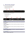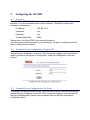
1
RV-SMB UHF/VHF Rack Mountable Network Attached Radio Modem Technical Manual Version A1 November 2012 Raveon Technologies Corporation 2461 Impala Drive Carlsbad, CA 92010 - USA www.ravtrack.com Table of Contents 1. General Information about the RV-SMB .................................................................. 3 1.1 Congratulations! ................................................................................................. 3 1.2 NOTICE ............................................................................................................. 3 1.3 Safety / Warning Information .............................................................................. 3 Blasting Caps and Blasting Areas............................................................................. 3 Potentially Explosive Atmospheres ........................................................................... 3 1.4 Safety Training information ................................................................................ 3 2. Overview ................................................................................................................... 4 2.1 Features ............................................................................................................. 4 3. Specifications............................................................................................................ 5 3.1 General .............................................................................................................. 5 3.2 User Input and Output Signals ........................................................................... 5 4. Electrical Inputs and Outputs .................................................................................... 6 4.1 LEDs .................................................................................................................. 6 Status LED ............................................................................................................... 6 Power LED ............................................................................................................... 6 The STAT LED will indicate unit function, and will vary according to the radio module within the RV-SMB. ..................................................................................... 6 4.2 AC Power ........................................................................................................... 6 4.3 Network I/O ........................................................................................................ 6 4.4 GPS TNC Connector .......................................................................................... 7 4.5 RF N-Type Connector ........................................................................................ 7 5. Configuring the RV-SMB ......................................................................................... 8 5.1 Overview ............................................................................................................ 8 5.2 Terminal Server Configuration Via Web GUI ..................................................... 8 5.3 Terminal Server Configuration Via Telnet .......................................................... 8 5.4 Terminal Server Configuration Via Serial Console ............................................. 9 5.5 Settings Required for Proper Terminal Server Operation ................................... 9 6. Operation ................................................................................................................ 11 6.1 Operating in Single-Radio mode. ..................................................................... 11 6.2 Operating In Reserve-Standby Mode ............................................................... 11 6.3 Operating In Hot-Standby Mode....................................................................... 11 7. Troubleshooting ...................................................................................................... 12 Symptom: Cannot enter Command Mode on radio module .................................... 12 Symptom: Cannot transmit from Radio B ............................................................... 12 1. General Information about the RV-SMB 1.1 Congratulations! Congratulations on your purchase of a RV-SMB Network Attached Radio Modem device. Please take a few minutes to read this manual carefully. The information presented here will allow you to derive maximum performance from your radio modem base station. After reading it, keep the manual handy for quick reference, in case questions arise later on. 1.2 NOTICE There are no user-serviceable points inside this transceiver. All service work must be referred to your Authorized Service Center or Raveon Technologies Service Department. 1.3 Safety / Warning Information Blasting Caps and Blasting Areas To avoid possible interference with blasting operations, turn off this device when you are near electrical blasting caps, in a blasting area, or in areas posted: “Turn off twoway radio.” Obey all signs and instructions. Potentially Explosive Atmospheres Turn off your radio prior to entering any area with a potentially explosive atmosphere. Do not install this product for use in areas with potentially explosive atmospheres. Sparks in a potentially explosive atmosphere can cause an explosion or fire resulting in bodily injury or even death. Note: The areas with potentially explosive atmospheres referred to above include fueling areas such as below decks on boats, fuel or chemical transfer or storage facilities, areas where the air contains chemicals or particles, such as grain, dust or metal powders, and any other area where you would normally be advised to turn off your vehicle engine. Areas with potentially explosive atmospheres are often but not always posted. 1.4 Safety Training information This radio is restricted to occupational use. Work related operations are permitted only when the radio operator has the knowledge to control the exposure conditions of its passengers and bystanders by maintaining the minimum separation distance. Failure to observe these restrictions may result in exceeding the regulatory exposure limits. 2. Overview The RV-SMB is a 1U rack-mountable (19”) high-speed UHF/VHF network attached radio modem chassis, with options for redundant radio modems of ½ to 5 watts RF power output, redundant power supply, and GPS transponder receiver. The RV-SMB is generally configured for operation as a GPS transponder base, with a redundant receiver and power supply. 2.1 Features AC 100-250V, 50-60Hz. Optional redundant power supply. Optional redundant radio module, which can be configured in reserve-standby mode (backup radio is powered down until it is needed) or hot-standby mode (backup radio is always powered). SENA PS410 terminal server. Automatic RF output switching. Dual GPS RF connections, enabling hot-standby of GPS-enabled radio modules. 3. Specifications 3.1 General Size .......................................................................................... 482.6mm X 45.0mm X 375.0mm Weight .................................................................................................................................... 18 lbs Radio Module Serial Communication Rates (programmable) .................. 9600, 14400, 19200, 38400, 115200 Operating temperature range ......................................................................................................30°C to +60°C Storage temperature range .......................................................................................................... 0ºC to +50ºC Internal fuse 3.2 ......................................................................................................................................... 6A User Input and Output Signals Network Interface ........................................................................................ 10/100 Base-Tx RJ-45 Connector Console Interface ............................................................................................ RS-232 DB-9, 9600 baud, DTE Transceiver RF ..................................................................................................................... 50 ohm N-Type GPS Antenna connector option .................................................... TNC 50 ohm (2), 3.3V for amplified antenna Power Connector ........................................................................................................................ IEC C14 Inlet 4. Electrical Inputs and Outputs The front of the <bs_pn> has these features: 1. Radio A Power and Status Indicators 2. Radio B Power and Status Indicators 3. SENA PS410 Front Panel The rear of the <bs_pn> has these features: 4. IEC C14 Power Inlet 5. RJ-45 Network I/O Connector 6. TNC GPS Jack (2) 7. N-Type RF Jack 4.1 LEDs The status LEDs visually show the current status of the radio, as well as terminal server power and activity. Status LED The STAT LED will indicate unit function, and will vary according to the radio module within the RV-SMB. Power LED The STAT LED will indicate unit function, and will vary according to the radio module within the RV-SMB. 4.2 AC Power AC power is supplied via the IEC C14 power inlet. The power inlet is switched, and contains one replaceable 6A fuse. 4.3 Network I/O The Network I/O is used with an RJ-45 terminated patch cable to connect to a network 10-BaseT or 100-BaseTX capable switch. 4.4 GPS TNC Connector The I/O connector for GPS is a 50-ohm TNC jack, and is intended for use with a 50-ohm GPS antenna. 4.5 RF N-Type Connector The I/O connector for RF is a 50-ohm N-Type jack, and is intended for use with a 50ohm radiating element. 5. Configuring the RV-SMB 5.1 Overview The RV-SMB’s SENA PS410 terminal server can be configured via the network interface, or via the front panel serial console interface. The default configuration information is listed here: IP Address: 192.168.161.5 Username: root Password: root Console Baud Rate: 9600 Please refer to the Sena PS410 user manual, located at http://www.sena.com/products/device_servers/hd_ps_x10.php, for additional terminal server configuration information. 5.2 Terminal Server Configuration Via Web GUI To configure the terminal server via the web GUI, use a web browser to connect to the terminal server’s IP address, on port 80. Once connected, logging in at the prompt will make it possible to change the IP configuration, serial port configuration, and other settings. 5.3 Terminal Server Configuration Via Telnet To configure the terminal server via the Telnet interface, open a Telnet session with the terminal server’s IP address, on port 23. Once connected, logging in at the prompt will bring up a BusyBox shell. Entering the command ‘editconf’ will start a text-based configuration menu. 5.4 Terminal Server Configuration Via Serial Console To configure the terminal server via the serial console port, open a terminal emulator, set the baud rate to 9600, and connect to the console port with a null modem cable. Once connected, logging in at the prompt will bring up a BusyBox shell. Entering the command ‘editconf’ will start a text-based configuration menu. 5.5 Settings Required for Proper Terminal Server Operation If a factory reset is performed on the terminal server, several settings will need to be manually reconfigured. /serial/*1/Port title = Radio A /serial/*2/Port title = Radio B /serial/*1/hostmode/Port number = 5001 /serial/*2/hostmode/Port number = 5002 /serial/*1/hostmode/Telnet Support = Enable /serial/*2/hostmode/Telnet Support = Enable /serial/*1/hostmode/DTR option = High when TCP/UDP is opened /serial/*2/hostmode/DTR option = High when TCP/UDP is opened /serial/*1/parameter/Baudrate = 38400 /serial/*2/parameter/Baudrate = 38400 /serial/*1/parameter/Inter_character_timeout = 20 /serial/*2/parameter/Inter_character_timeout = 20 6. Operation Once the RV-SMB is turned on, the terminal server will start. Radio A is always powered, and Radio B is only powered when there is an active telnet session connected to its TCP/IP port. Similarly, the internal antenna relay will remain connected to Radio A, except when there is no active telnet session connected to Radio A and there is an active telnet session connected to Radio B. Connected to Radio A Both radios powered Radio A has antenna Not Connected to Radio B Radio A powered Radio A has antenna Connected to Radio B Not Connected to Radio A Both radios powered Radio B has antenna Radio A powered Radio A has antenna Default TCP/IP ports: Radio A: 5001 Radio B: 5002 6.1 Operating in Single-Radio mode. When only one radio is installed, it will be configured as Radio A. Starting a telnet session with port 5001 will connect to Radio A. 6.2 Operating In Reserve-Standby Mode When two radio modules are installed, it is possible to operate in reserve-standby mode (backup radio is powered down until it is needed), use Radio A as the primary radio and end the telnet session with Radio A when it is experiencing failure. Note: Do not transmit while switching radios. 6.3 Operating In Hot-Standby Mode When two radio modules are installed, it is possible to operate in hot-standby mode (backup radio is always powered, with TDMA timing synced to GPS). To do this, use Radio B as the primary and only start a telnet session with Radio A when Radio B is experiencing failure. Note: Do not transmit while switching radios. 7. Troubleshooting Symptom: Cannot enter Command Mode on radio module Solution #1. Verify the serial port baud rate on the modem and terminal server. This is difficult if it is set wrong, because you cannot enter the command mode to check it. Try all possible baud rates, and see if one of them works with the modem. Solution #2. Make sure that Telnet Support is enabled in the terminal server. Symptom: Cannot transmit from Radio B Solution #1. Verify that there is no Telnet session connected to Radio A’s port. Solution #2. Make sure that the terminal server’s DTR mode Limited One Year Warranty If within one year from date of purchase, this product fails due to a defect in material or workmanship, Raveon Technologies, Incorporated will repair or replace it, at Raveon’s sole discretion. This warranty is extended to the original consumer purchaser only and is not transferable. This warranty does not apply to: (a) product damage caused by accident, dropping or abuse in handling, acts of God or any negligent use; (b) units which have been subject to unauthorized repair, opened, taken apart or otherwise modified; (c) units not used in accordance with instructions; (d) damages exceeding the cost of the product; (e) batteries; (f) the finish on any portion of the product, such as surface and/or weathering, as this is considered normal wear and tear; (g) transit damage, initial installation costs, removal costs, or reinstallation costs; (h) damage due to lighting, floods, fire, or earthquakes, (i) connectors, (j) antennas, or (k) belt clips. RAVEON TECHNOLOGIES INCORPORATED WILL NOT BE LIABLE FOR INCIDENTAL OR CONSEQUENTIAL DAMAGES. SOME STATES DO NOT ALLOW THE EXCLUSION OR LIMITATION OF INCIDENTAL OR CONSEQUENTIAL DAMAGES, SO THE ABOVE LIMITATION OR EXCLUSION MAY NOT APPLY TO YOU. THIS WARRANTY IS IN LIEU OF ALL OTHER EXPRESS OR IMPLIED WARRANTIES. ALL IMPLIED WARRANTIES, INCLUDING THE WARRANTY OF MERCHANTABILITY AND THE WARRANTY OF FITNESS FOR A PARTICULAR PURPOSE, ARE HEREBY MODIFIED TO EXIST ONLY AS CONTAINED IN THIS LIMITED WARRANTY, AND SHALL BE OF THE SAME DURATION AS THE WARRANTY PERIOD STATED ABOVE. SOME STATES DO NOT ALLOW LIMITATIONS ON THE DURATION OF AN IMPLIED WARRANTY, SO THE ABOVE LIMITATION MAY NOT APPLY TO YOU. This warranty gives you specific legal rights and you may also have other rights which vary from state to state. Warranty service is available by mailing postage prepaid to: Raveon Technologies Corporation 2461 Impala Drive Carlsbad, CA 92010 To obtain warranty service, include a copy of the original sales receipt or invoice showing the date, location, and price of purchase. Include a written description of the problem with the product, a phone number and name of person who may be contacted regarding the problem, and the address to where the product should be returned. Products repaired under warranty will typically have their program memories erased and reset to factory default settings.