1
SPECTRUM Enterprise Manager
Device Management
Titlepae
SmartSwitch Router
Supports Management Module SM-CSI1091
and SM-ENT1001
Notice
Restricted Rights Notice
Aprisma Management Technologies, Inc. (Aprisma), reserves the right to make
changes in specifications and other information contained in this document without
prior notice. The reader should in all cases consult Aprisma to determine whether
any such changes have been made.
(Applicable to licenses to the United States Government only.)
1. Use, duplication, or disclosure by the Government is subject to restrictions as
set forth in subparagraph (c) (1) (ii) of the Rights in Technical Data and
Computer Software clause at DFARS 252.227-7013.
The hardware, firmware, or software described in this manual is subject to change
without notice.
Aprisma Management Technologies, Inc.
121 Technology Drive
Durham NH 03824
IN NO EVENT SHALL APRISMA, ITS EMPLOYEES, OFFICERS, DIRECTORS,
AGENTS, OR AFFILIATES BE LIABLE FOR ANY INCIDENTAL, INDIRECT,
SPECIAL, OR CONSEQUENTIAL DAMAGES WHATSOEVER (INCLUDING BUT
NOT LIMITED TO LOST PROFITS) ARISING OUT OF OR RELATED TO THIS
MANUAL OR THE INFORMATION CONTAINED IN IT, EVEN IF APRISMA HAS
BEEN ADVISED OF, KNOWN, OR SHOULD HAVE KNOWN, THE POSSIBILITY
OF SUCH DAMAGES.
2. (a) This computer software is submitted with restricted rights. It may not be
used, reproduced, or disclosed by the Government except as provided in
paragraph (b) of this Notice or as otherwise expressly stated in the contract.
(b) This computer software may be:
(1) Used or copied for use in or with the computer or computers for which
it was acquired, including use at any Government installation to which
such computer or computers may be transferred;
Copyright © January 2001 by Aprisma Management Technologies. All rights
reserved.
(2) Used or copied for use in a backup computer if any computer for which
it was acquired is inoperative;
Printed in the United States of America.
Order Number: 9032814-05
(3) Reproduced for archival or backup purposes;
Aprisma Management Technologies, Inc.
121 Technology Drive
Durham NH 03824
(4) Modified, adapted, or combined with other computer software, provided
that the modified, combined, or adapted portions of the derivative
software incorporating restricted computer software are made subject
to the same restricted rights;
SPECTRUM, the SPECTRUM IMT/VNM logo, DCM, IMT, and VNM are registered
trademarks, and SpectroGRAPH, SpectroSERVER, Inductive Modeling
Technology, Device Communications Manager, and Virtual Network Machine
are trademarks of Aprisma or its affiliates.
(5) Disclosed to and reproduced for use by support service contractors in
accordance with subparagraphs (b) (1) through (4) of this clause,
provided the Government makes such disclosure or reproduction
subject to these restricted rights; and
Ethernet is a trademark of Xerox Corporation.
(6) Used or copied for use in or transferred to a replacement computer.
(c) Notwithstanding the foregoing, if this computer software is published
copyrighted computer software, it is licensed to the Government, without
disclosure prohibitions, with the minimum rights set forth in paragraph (b) of
this clause.
Virus Disclaimer
Aprisma makes no representations or warranties to the effect that the Licensed
Software is virus-free.
Aprisma has tested its software with current virus checking technologies. However,
because no anti-virus system is 100% reliable, we strongly caution you to write
protect and then verify that the Licensed Software, prior to installing it, is virus-free
with an anti-virus system in which you have confidence.
(d) Any other rights or limitations regarding the use, duplication, or disclosure
of this computer software are to be expressly stated in, or incorporated in,
the contract.
(e) This Notice shall be marked on any reproduction of this computer software, in
whole or in part.
SPECTRUM Enterprise Manager
Page 2
SmartSwitch Router
Contents
INTRODUCTION
5
Purpose and Scope ........................................................5
Required Reading ...........................................................5
Overview .........................................................................6
Supported Devices..........................................................7
Control Module ............................................................7
Line Modules ...............................................................7
The SPECTRUM Model ..................................................8
TASKS
10
DEVICE VIEWS
11
Interface Device View ...................................................11
Interface Icons ...........................................................12
Interface Label Icon Subviews Menu.........................13
Interface Status View .............................................14
Secondary Address Panel .....................................14
Chassis Device View ....................................................14
Chassis Module Icons ...............................................15
Module Identification Labels ..................................15
Interface Labels .....................................................15
Chassis Module Icon Subviews Menu ...................16
Router Module Detail View .................................16
Line Module Icon Subviews Menu .........................17
Chassis Device View for the
6-SSRM-02 ............................................................17
SPECTRUM Enterprise Manager
DEVICE TOPOLOGY VIEWS
19
Chassis Device Topology View.....................................19
Interface Device Topology View ................................... 19
APPLICATION VIEWS
21
Main Application View................................................... 21
Supported Applications ................................................. 22
Common Applications ............................................... 22
Optional Applications................................................. 22
Device-Specific Applications .....................................23
SSR Chassis Application (SSR_ChasApp) ...............23
Module Hardware View.......................................... 23
Module Hardware ............................................... 23
Port Hardware View ............................................... 24
Port Hardware .................................................... 24
Environment View .................................................. 24
Service Status View ............................................... 26
Container Application (ContainerApp)....................... 26
Container Resource Information............................ 27
Container Type Report .......................................... 27
Container Logical Information................................ 28
Container Physical Information .............................. 29
Container Network Address Information ................ 29
VRRP Application (rfc2338App) ................................ 29
PERFORMANCE VIEWS
Page 3
30
SmartSwitch Router
Contents
Contents
Device Performance View.............................................31
IF Performance View ....................................................31
CONFIGURATION VIEWS
32
Interface Configuration View .........................................32
Capacity Application Configuration View ......................33
Task Table..........................................................34
Capacity - Memory Table View..................................34
Capacity - CPU Table View .......................................35
SmartSwitch Router Configuration View .......................36
Interface Configuration Table .............................37
Redundancy and Model Reconfiguration Options View
37
Interface Address Translation Table..........................39
SmartSwitch Router TFTP View................................39
VRRP Configuration View .............................................40
VRRP Operations Table .....................................41
CORE WATCH APPLICATION
45
MODEL INFORMATION VIEW
46
INDEX
47
SPECTRUM Enterprise Manager
Page 4
SmartSwitch Router
Introduction
This section introduces the SPECTRUM Device Management documentation for SmartSwitch Router devices.
This introduction contains the following topics:
document. For general information about device
management using SPECTRUM and explanations
of SPECTRUM functionality and navigation
techniques, refer to the topics listed under
Required Reading.
• Purpose and Scope
• Required Reading
• Overview (Page 6)
• Supported Devices (Page 7)
Required Reading
• The SPECTRUM Model (Page 8)
To use this documentation effectively, you must
be familiar with the information covered by the
other SPECTRUM online documents listed below.
Purpose and Scope
Use this document as a guide for managing the
SmartSwitch Router devices described on Page 7
with SPECTRUM management modules SMCSI1091 and SM-ENT1001 (designed for the 6SSRM-02 module). This document describes the
icons, menus, and views that enable you to
remotely monitor, configure, and troubleshoot
SmartSwitch Router devices through software
models in your SPECTRUM database.
Information specific to SM-CSI1091 and SMENT1001 is what is primarily included in this
SPECTRUM Enterprise Manager
Page 5
• Getting Started with SPECTRUM for
Operators
• Getting Started with SPECTRUM for
Administrators
• How To Manage Your Network with
SPECTRUM
• Autodiscovery User’s Guide
• Core Watch User’s Guide
• SPECTRUM Views
• SPECTRUM Menus
• SPECTRUM Icons
SmartSwitch Router
Introduction
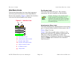
Overview
Overview
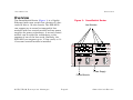
The SmartSwitch Router (Figure 1) is a Gigabit
Ethernet/wide-area router that consists of a fancooled 8-slot or 16-slot chassis. The SSR-8000
can support up to seven hot-swappable line
modules with one control module and two power
supplies for power redundancy. A second control
module can be added for redundancy at the
expense of one of the line cards. Similarly, the
SSR-8600 can support up to 15 line cards, or 14
if a second control module is installed.
Figure 1: SmartSwitch Router
Line Modules
SmartSwitch
ROUTER
Power Supply
Control Module
SPECTRUM Enterprise Manager
Page 6
SmartSwitch Router
Introduction
Supported Devices
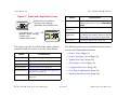
Supported Devices
Table 1 through Table 4 list the line modules that
are supported:
The SmartSwitch Router includes a Control
Module and Line Modules as described below:
Table 1: Cabletron Devices
Device
Control Module
The control module is used to manage the line
modules. It is responsible for maintaining route
table and bridge table information, SNMP
management, and system housekeeping. It has a
200 MHz R5000 processor that runs spanning
tree algorithms and routing protocols such as
RIP, BGP4 and OSPF. It has two front panel
interfaces for side and out-of-band management.
Table capacity is based on the amount of memory
within the control module. Configurations may be
either 64 MB for up to 50,000 routes, or 128 for
up to 100,000 routes.
Line Modules
The line modules determine the number of flows
that a SmartSwitch Router can handle. Line
modules with 4 MB of memory can support up to
500,000 L4 flows, with 16 MB they can support
up to 2,000,000 flows. The line modules store
bridge table and MAC address information from
the L2 table on the control module.
SPECTRUM Enterprise Manager
Page 7
Model Type
MM
SSR-32000
SmartSwRtr32
SM-CSI1091
SSR-8600
SSR-8000
SSR-3000
SSR-2100
SSR-2000
SSR-1200
IA-1100
SmartSwRtr
SM-CSI1091
Table 2:
Device
Enterasys Devices
Model Type
MM
X-Pedition ER16 SmartSwRtr32
SM-CSI1091
X-Pedition
X-Pedition
X-Pedition
X-Pedition
SmartSwRtr
SM-CSI1091
6_SSRM_02
SM-ENT1001
8600
8000
2100
2000
6-SSRM-02
SmartSwitch Router
Introduction
The SPECTRUM Model
Table 3: Riverstone Devices
Device
Model Type
MM
RS-32000
SmartSwRtr32
SM-CSI1091
RS-8600
RS-8000
RS-3000
RS-2100
RS-2000
IA-1200
IA-1100
SmartSwRtr
SM-CSI1091
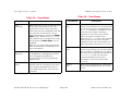
The model types for the SmartSwitch Router
devices are SmartSwRtr, 6_SSRM_02 for the
6-SSRM-02, and SmartSwRtr32 for the RS-3200
and the X-Pedition ER16. Once modeled, the type
of device is displayed in the Device icon’s Model
Type label. The Model Type label is updated to
indicate the SSR type e.g., SSR-8000 or SSR8600.
Modeling results in the creation of Device icons
that represent the devices and Application icons
that represent their supported applications.
Table 4: Terayon Devices
Device
Model Type
MM
BE2xx
BE2xx
SM-TRN1000
TL1000
TL1000MC
SM-TRN1000
TLGateway
TLGWay
SM-TRN1000
Note:
Note:
The SPECTRUM Model
The Device icons contain double-click zones and
provide access to Icon Subviews menus that let
you perform device management activities such
as those listed in Tasks on Page 10.
As Figure 1 shows, the appearance of the Device
icons varies slightly depending on the kind of view
it appears in.
Compaq, DEC and Olicom variants of
2000, 8000 and 8600 are also
managed as SmartSwRtr from SMCSI1091.
SPECTRUM Enterprise Manager
Page 8
SmartSwitch Router
Introduction
Figure 2:
Model Name
The SPECTRUM Model
Small and Large Device Icons
Option
Small Device icon appears in
Topology, Device Topology,
Application, and Container views.
SS8000
Large Device icon
appears in Device Topology,
Location, and
Interface Device views.
Fault Isolation
Opens the Fault Isolation View. For
information on this, refer to SPECTRUM
Views.
Model
Information
Model Information View (Page 46)
Primary
Application
Menu options that let you select Routing,
Gen Bridge App, MIB-II, Ethernet App or
rfc2338App as the primary application.
Core Watch
Core Watch Application (Page 45)
Model Name
SSR-8600
The device-specific Icon Subviews menu options
available from the Device icon are listed below.
Option
Accesses the...
The following views are accessible from the Device
icon for the SmartSwitch Router.
• Device Views (Page 11)
Accesses the...
• Device Topology Views (Page 19)
Device
Device Views (Page 11)
Dev Top
Device Topology Views (Page 19)
Application
Application Views (Page 21)
• Performance Views (Page 30)
Configuration
Configuration Views (Page 32)
• Configuration Views (Page 32)
• Application Views (Page 21)
• Core Watch Application (Page 45)
Rtr Redundancy Redundancy and Model Reconfiguration
Options View (Page 37)
Chassis
SSR Chassis Application (SSR_ChasApp)
(Page 23)
SPECTRUM Enterprise Manager
Page 9
• Model Information View (Page 46)
SmartSwitch Router
Tasks
This section contains an alphabetical list of device management tasks, with each task providing one or more
links to views that let you perform the task.
Application Information (examine)
Model the SmartSwitch Router (modify)
• Application Views (Page 21)
• The SPECTRUM Model (Page 8)
Device (configure)
Port Statistics (monitor)
• Device Views (Page 11)
• Device Performance View (Page 31)
• IF Performance View (Page 31)
Enable/Disable a Port (examine/modify)
Set Automatic Configuration Updates
(modify)
• Interface Status View (Page 14)
• Admin. Status (Page 33)
• Admin Status (Page 37)
• Core Watch Application (Page 45)
Identify Current Protocols (monitor)
Set Interface Thresholds (modify)
• Service Status View (Page 26)
• IF Thresholds (Page 17)
Interface or Port Operation (monitor)
•
•
•
•
•
Set Redundant Routes (modify)
Device Views (Page 11)
Interface Label Icon Subviews Menu (Page 13)
Device Topology Views (Page 19)
Operation Status (Page 37)
Core Watch Application (Page 45)
SPECTRUM Enterprise Manager
• Core Watch Application (Page 45)
Transfer Configuration File (modify)
• Configuration Views (Page 32)
P a g e 10
SmartSwitch Router
Device Views
This section describes the Device views and subviews available for models of SmartSwitch Router devices in
SPECTRUM.
These views display icons and labels that
represent the device, its modules and ports or
interfaces, and applications. This view is
described in general under SPECTRUM Views
within the SPECTRUM online documentation. The
information provided within this document is
specific to this device. The following Device views
are available for the SmartSwitch Router:
Figure 3:
Interface Device View
SpectroGRAPH: Device: IP Address
File
View
Tools
Name
Contact
Description
Location
Helpÿ
Bookmarks
System Up Time
Manufacturer
Device Type
Serial Number
Network Address
Primary Application
Model Name
Find Phy Addr
• Interface Device View
Interface Description
SmartSwRtr
• Chassis Device View (Page 14)
1
• Chassis Device View for the 6-SSRM-02
(Page 17)
OFF
2
OFF
3
OFF
4
OFF
5
OFF
6
OFF
7
OFF
ethernet
ethernet
ethernet
ethernet
ethernet
ethernet
ethernet
et.2.1
et.2.2
et.2.3
et.2.4
et.2.5
et.2.6
et.2.7
0:0:C6:FF:0:41 0:0:C6:FF:0:41 0:0:C6:FF:0:41 0:0:C6:FF:0:41 0:0:C6:FF:0:41 0:0:C6:FF:0:41 0:0:C6:FF:0:41
0:0:0:0
0:0:0:0
0:0:0:0
0:0:0:0
0:0:0:0
0:0:0:0
0:0:0:0
0
8
0
OFF
9
0
OFF
10
0
ON
11
0
ON
0
OFF
12
13
0
ON
OFF
14
ethernet
ethernet
ethernet
ethernet
ethernet
ethernet
ethernet
et.2.8
et.3.1
et.3.2
et.3.3
et.3.4
et.3.5
et.3.6
0:0:C6:FF:0:41 0:0:C6:FF:0:41 0:0:C6:FF:0:41 0:0:C6:FF:0:41 0:0:C6:FF:0:41 0:0:C6:FF:0:41 0:0:C6:FF:0:41
0:0:0:0
0:0:0:0
0:0:0:0
0:0:0:0
0:0:0:0
0:0:0:0
0:0:0:0
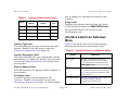
Interface Device View
Access: From the Icon Subviews menu for the Device
icon, select Device > Interface.
0
0
0
0
0
0
0
This view displays icons (Figure 3) that represent
the interfaces for the SmartSwitch Router.
SPECTRUM Enterprise Manager
P a g e 11
SmartSwitch Router
Device Views
Interface Device View
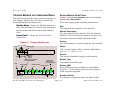
Interface Icons
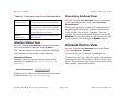
This section describes the icons that represent
the front panel interfaces on the SmartSwitch
Router line modules. Figure 4 shows the interface
icon and its labels/double-click zones.
Figure 4:
(a)
Interface Icon
Port Number Label
This label identifies this port. The number
represents the port number on this module.
Note:
Note:
Double-clicking on the “down arrow”
in the Interface Icon allows you to
drill down through the layers, starting
with the physical and going to the IP
Forwarding layer.
(b)
1
OFF
(c)
ethernet
(d)
et.2.1
0:0:C6:FF:0:41 (e)
0:0:0:0
(f)
0
(g)
a
Port Number Label
b
Administrative Status Label
c
Interface Type Label
d
Interface Description Label
e
Physical Address Label
f
IP Address Label
g
Gauge Label
SPECTRUM Enterprise Manager
Administrative Status Label
This label displays the administrative state of this
port. It also provides double-click access to the IF
Status (Page 13) view.
Table 5 lists the possible states relative to the
application selected. The default application for
this view is Physical (MIB-II). To select the
application to be displayed (Physical or Bridging),
click the Filter menu button in the Interface
Options panel.
P a g e 12
SmartSwitch Router
Device Views
Table 5:
Color
Interface Device View
you to change the address and mask for this
interface.
Interface Status Label Colors
Operational Administrative
Status
Status
Label
Text
Green
ON
ON
ON
Blue
OFF
OFF
OFF
Yellow
OFF
ON
OFF
Red
Testing
Test
TST
Gauge Label
Displays the statistic selected from the Gauge
Control Panel described in SPECTRUM Views
and provides double-click access to the
Performance view.
Interface Label Icon Subviews
Menu
Interface Type Label
This label displays the type of network interface
module. Double-click this label to open the
Interface Configuration View (Page 32).
Table 6 lists each of the Icon Subviews menu
selections available for the Interface Label.
Table 6:
Interface Description Label
This label identifies the type of network to which
this interface is connected. Double-click the label
to open the Model Information View (Page 46) for
the interface.
Physical Address Label
This label displays the physical (MAC) address of
the interface.
IP Address Label
This label displays the IP address for the
interface. Double-click the label to open the
Secondary Address Panel (Page 14), which allows
SPECTRUM Enterprise Manager
Interface Label Icon Subviews Menu
Option
Opens the ...
IF Details
Interface breakdown detail view
displays three pie charts of packet,
error, and discard information See
SPECTRUM Views for more details.
IF Status
Interface Status View allows you to set
the operational status (turn the port
on or off) through the Administrative
Status button.
IF Configuration
Interface Configuration View (Page 32)
provides interface specific
configuration information.
P a g e 13
SmartSwitch Router
Device Views
Chassis Device View
Table 6: Interface Label Icon Subviews Menu
Secondary Address Panel
Secondary
Address Panel
Secondary Address Panel displays the
current IP address for this interface.
Access: From the Icon Subviews menu for the Interface
icon in the Interface Device view, select Secondary
Address Panel.
IF Thresholds
Interface Threshold view, which lets
you set the on/off alarm thresholds
for load, packet rate, error rate, and
% discarded for the interface.
Model
Information
Model Information View (Page 46) for
this interface.
This panel provides a table of IP addresses and
masks obtained from the Address Translation
Table within the device’s firmware. You can
change the current address displayed in the IP
Address field by selecting an entry from the table
in this panel and clicking the Update button.
Interface Status View
Chassis Device View
Access: From the Icon Subviews menu for the Interface
icon in the Interface Device view, select IF Status.
Access: From the Icon Subviews menu for the Device
icon, select Device > Chassis.
The Interface Status view provides the following
information on the status of the interface:
This view (Figure 5) shows an example of a
Chassis Device View, which displays the modules
contained within the chassis, their location, and
ports. The ports are represented by dynamic icons
that display operational status.
Operational Status
Displays the current operational state of the
interface is displayed (Up, Down, Testing, or
Unknown).
Administrative Status
Allows you to select the desired operational state
of the interface (On, Off, or Testing).
SPECTRUM Enterprise Manager
P a g e 14
SmartSwitch Router
Device Views
Chassis Device View
Figure 5:
Chassis Module Icons
Chassis Device View
SpectroGRAPH: Device: IP Address
File
View Tools
Bookmarks
Module Identification Labels
Manufacturer
Device Type
Primary Application
online
These icons (Figure 6) represent the physical
modules as installed in the chassis.
System Up Time
Network Address
Model Name
Contact
Description
Location
ÿ
Help
Serial Number
These labels display the following information:
online
online
ON
ON ÿ ON
ON
ON
Off
ON
Off
ON
online
ON ÿ Off
Off
ON
Off
Off
Off
Off
online
ON ÿ ON
ON
ON
Off
Off
Off
Off
online
ON ÿ ON
ON
ON
ON
Off
Off
Off
ON
Off
online
Slot Number Label
The location of the module within the chassis.
ÿ
Model Type Label
The type of network interface module in the
chassis slot.
Chassis Module Icons
Interface Labels
These labels display the following information:
Interface Type Label
The number and type for this interface.
Interface Status Label
The current operating status of this interface.
SPECTRUM Enterprise Manager
P a g e 15
SmartSwitch Router
Device Views
Chassis Device View
Chassis Module Icon Subviews Menu
Router Module Detail View
The only Icon Subviews menu selection specific to
the Chassis Module for each device within the
SmartSwitch Router chassis are:
Access: From the Icon Subviews menu for the Chassis
Module, select Board Detail.
Module Notes - Opens the Module Notes window, which allows you to write and save notes
for the selected module within this Chassis
view.
Board Detail - Opens the Router Module
Detail View.
Figure 6:
Slot#
Fan Temp PSU
128
3.1.0.0
Control Module type
Firmware
Revision
Number
Service
The service identifier string for this module.
Control Module
Access to Chassis Module
Icon Subviews Menu
Slot#
Module Status
Access to the
Interface Label
Icon Subviews Menu
Interface Number
Interface status
4
online
1 ON 2 ON 3 ON 4 ON 5 ON 6 ON 7 ON 8 ON
Ethernet1000TX 100Mb 100Mb
Module Type
Module Description
The description of the module. For the Control
Module, it should have the software version, the
amount of dynamic RAM, and flash RAM.
Status
The current status of this module. Valid values
are: online, and offline.
Memory (Mb)
Control2
Slot
The physical slot number of the module.
Version
The alphanumeric version string for this module.
Chassis Module Icon
Color-coded status
0
This view displays the following information:
10Mb
100Mb
100Mb
100Mb 100Mb
Typical Line Module
100Mb
Connection speed
SPECTRUM Enterprise Manager
Module Type
The physical module type.
Memory (Mb)
System Memory size available on the Module.
reports -1 if no memory exists on this module,
such as power supplies.
Number of Ports
The number of physical ports on this module.
P a g e 16
SmartSwitch Router
Device Views
Chassis Device View for the 6-SSRM-02
Line Module Icon Subviews Menu
Table 7 describes each of the device-specific Icon
Subviews menu options available for the Line
Module.
Table 7:
Line Module Icon Subviews Menu
Option
Chassis Device View for the
6-SSRM-02
Access: From the Icon Subviews menu for the
6-SSRM-02, select Device > Chassis.
This view displays the Chassis Information for the
6-SSRM-02 device:
Opens the ...
IF Performance
IF Performance View (Page 31).
IF Details
Interface breakdown detail view which
displays three pie charts of packet,
error, and discard information
described in detail in the SPECTRUM
Views documentation.
IF Status
Interface Status View (Page 14) allows
you to set the operational status (turn
the port on or off) through the
Administrative Status button.
IF Configuration
Interface Configuration View (Page 32)
provides interface specific
configuration information.
Network
Information Panel
Network Information Panel.
IF Thresholds
Interface Threshold View allows you to
view and set the thresholds for this
interface.
Power Redundancy
Displays the source of power for the chassis.
Redundant indicates that power from the
secondary source is being used for the chassis.
NON_redundant indicates that power from the
primary source is being used.
PS #1 Status
The status for power supply one.
PS #2 Status
The status for power supply two.
Model Information Model Information View (Page 46) for
this interface.
SPECTRUM Enterprise Manager
P a g e 17
SmartSwitch Router
Device Views
Chassis Device View for the 6-SSRM-02
Chassis Fans
Displays the operation state for the chassis fans.
Table 8 displays the state and color indications
for the power supplies and chassis fans:
Table 8: Chassis Information Status
Color
Definition
Green
Normal
Gray
Not Installed
Red
Not operational
Blue
Unknown
SPECTRUM Enterprise Manager
P a g e 18
SmartSwitch Router
Device Topology Views
This section provides brief descriptions of the Device Topology views available for models of SmartSwitch
Router devices in SPECTRUM.
Device Topology views show the connections
between a modeled device and other network
entities. The SmartSwitch Router has two Device
Topology views:
• Chassis Device Topology View
• Interface Device Topology View
Chassis Device Topology View
Access: From the Icon Subviews menu for the Device
icon, select DevTop > Chassis.
Figure 7 shows an example of the Chassis Device
Topology view. The lower panel of the view uses
Interface icons to represent the device’s
serial/network I/O ports for a selected module.
The port labels in this view provide the same
information and menu options as those described
under the Interface Icons (Page 12).
SPECTRUM Enterprise Manager
Interface Device Topology
View
Access: From the Icon Subviews menu for the Device
icon, select DevTop > Interface.
The lower panel of the Interface Device Topology
view (Figure 7) uses interface icons to represent
the device’s serial/network I/O ports. These icons
provide the same information and menu options
as those in the Interface Device View (Page 11). If
there is a device connected to a particular
interface, a device icon appears on the vertical bar
above the interface icon with an icon representing
the network group that contains the device.
For further information on Device Topology views,
refer to SPECTRUM Views.
P a g e 19
SmartSwitch Router
Device Topology Views
Interface Device Topology View
Figure 7: Device Topology View
Interface DevTop View
Chassis DevTop View
Note:
Note:
SmartSwitch
ROUTER
File
View
Tools
Ether100
Ether100
Control
Ether100
In the Chassis Device Topology view,
only interfaces for a selected module
will be displayed. For the Interface
Device Topology view, all interfaces
for each module will be displayed.
Help
Bookmarks
Model Name
SmartSwRtr
Model Name
SSR-8000
1
OFF
2
OFF
3
OFF
4
OFF
ethernet
et.2.1
0:0:C6:FF:0:41
0:0:0:0
ethernet
et.2.2
0:0:C6:FF:0:41
0:0:0:0
ethernet
et.2.3
0:0:C6:FF:0:41
0:0:0:0
ethernet
et.2.4
0:0:C6:FF:0:41
0:0:0:0
0
0
0
0
SPECTRUM Enterprise Manager
P a g e 20
SmartSwitch Router
Application Views
This section describes the main Application view and the associated application-specific subviews available for
models of SmartSwitch Router devices in SPECTRUM.
Figure 8: Application View
Access: From the Icon Subviews menu for the Device
icon, select Application.
SpectroGRAPH: Application: IP Address
File
Main Application View
When a device model is created, SPECTRUM
automatically creates models for each of the
major and minor applications supported by the
device. The main Application view identifies all of
these application models, shows their current
condition status, and provides access to
application-specific subviews. Figure 8 shows this
view in the Icon mode. If you prefer the List mode,
which displays applications as text labels, select
View > Mode > List.
View
Tools
Help
Bookmarks
System Up Time
Network Address
Name
Contact
Description
Location
Manufacturer
Device Type
Primary Application
Serial Number
SSR-8000
SSR-8
-5 Routing
Bridging
Ethernet App
MIB II
SNMP2_Agent
GenRtrApp
CSIBridge
-5 Routing
Source Routing
SNMP2_Agent
ICMP
Span_Rt_App
IP Routing
Spanning Tree
ICMP_App
System
System2_App
GenRtrApp
SPECTRUM Enterprise Manager
P a g e 21
Span_Tree_App
EthernetApp
nettIfApp_001
ICMP_App
GenRtrApp
EthernetApp
System2_App
1
EthernetIfApp
SSRChasApp
SSR_ChasAp
SSR_ChasAp
CapacityApp
CapacityApp
CapacityApp
tIfApp_002
2
EthernetIfApp
SmartSwitch Router
Application Views
Supported Applications
Supported Applications
-
SPECTRUM’s applications can be grouped within
three general categories as follows:
• Common Applications
• Optional Applications
• Device-Specific Applications (Page 23)
Common Applications
For the most part, these applications represent
the non proprietary MIBs supported by your
device. Listed below (beneath the title of the
document that describes them) are some of the
common applications currently supported by
SPECTRUM.
The documents listed are available for
viewing at:
Note:
Note:
www.aprisma.com/manuals/
• Bridging Applications
- Spanning Tree
- Static
- Transparent
- PPP Bridging
- Source Routing
SPECTRUM Enterprise Manager
Translation
QBridge
• Routing Applications
- Generic Routing
- IP Routing
- Open Shortest Path First
• MIB II Applications
- SNMP
- IP
- ICMP
- TCP
- System2
- UDP
• Miscellaneous Applications
- Ethernet
- ctDownload
Optional Applications
•
•
•
•
P a g e 22
Routing Services (CtRouter)
DLM (DLM_Agent)
Standard RMON (RMONApp)
SecureFast VLAN (SFVLANApp)
SmartSwitch Router
Application Views
Supported Applications
Device-Specific Applications
Module Hardware View
The views and subviews available for
SmartSwitch Router device-specific applications
are described in the rest of this section, grouped
by major application as listed below:
Access: From the Icon Subviews menu for the
SSR_ChasApp Application icon, select Module Hardware.
• SSR Chassis Application (SSR_ChasApp)
This view provides information about the modules
installed in the chassis, such as slot location, and
module type.
• Container Application (ContainerApp) (Page 26)
Module Hardware
• VRRP Application (rfc2338App) (Page 29)
This section of the Module Hardware view
identifies the modules installed in the chassis by
providing the following information:
SSR Chassis Application
(SSR_ChasApp)
This major application (SSR_ChasApp) has a
single minor application: Capacity Application
Configuration View on Page 33 (CapacityApp). It
also provides the following application-specific
subviews:
• Module Hardware View
• Port Hardware View (Page 24)
• Environment View (Page 24)
• Service Status View (Page 26)
SPECTRUM Enterprise Manager
Module
Displays the location of the module in the
chassis.
Description
Describes the module installed in the location
listed under “Module.”
Ports
Displays the number of ports for that module.
Version
Displays the hardware version of that module.
Mem
The amount of memory on a module (in Mbytes).
P a g e 23
SmartSwitch Router
Application Views
Supported Applications
Service
The Aprisma service identifier string for this
card/module. Unique to a module in production,
used by Aprisma Service and Manufacturing to
identify shipped inventory.
Port Hardware View
Connector Type
Displays the type of port connector being used.
IF Index
Displays the entry in the MIB-ll Interface Table
corresponding to this port.
Environment View
Access: From the Icon Subviews menu for the
SSR_ChasApp Application icon, select Port Hardware.
Access: From the Icon Subviews menu for the
SSR_ChasApp Application icon, select Environment.
This view provides information about the ports for
all modules installed in the chassis, such as slot
number for the module, port number, and port
types.
This view provides information about the
conditions of the chassis, such as power supply
operation, and fan operation.
Port Hardware
Chassis ID
Displays the unique identification number for this
chassis.
This section of the Port Hardware view identifies
the ports on the line modules installed in the
chassis by providing the following information:
Num Slots
Displays the total number of slots for this chassis.
Module
Displays the location of the module in the
chassis.
Last Hot Swap
The time the module was last hot swapped.
Port
Displays the port number for that module.
Fan
Indicates whether or not the fan is functioning.
Port Type
Displays the type of port. For example “etherfast” for a Fast Ethernet port.
Temperature
Indicates whether or not temperature control is
functioning.
SPECTRUM Enterprise Manager
P a g e 24
SmartSwitch Router
Application Views
Supported Applications
Note that the selected model is highlighted on the
left, and three watches are shown on the right.
CM Backup State
Indicates status of the backup Control Module.
Note:
Note:
FabricStatewatch is shown as inactive.
Regardless of which Control Module
happens to be Primary, the
Administrator can set up an Alarm
Watch to be notified of the failure of
the backup module. Select the device,
then from the device menu select
Utilities>Watch Manager.
Manager Highlight
BackupCMwatch and make the watch
Active. The selected watch will now
2
The selected watch will now enter the Initial
watch status.
enter the Initial watch status.
Power Supply
Displays the status of each of the power supplies.
An Alarm Watch is applied to the power supplies
by default and the Administrator is notified at the
failure of either Primary or Secondary PSU.
Switch Fabric
If a redundant switch fabric is employed, this icon
indicates which is primary and which is backup.
The Administrator can set up an Alarm Watch on
the switch fabrics to activate if either device fails.
To do this:
1
Select device, then from device menu select
Utilities> Watch Manager.
SPECTRUM Enterprise Manager
Highlight FabricStatewatch and select
Activate.
Any change in the watched attributes, which are
polled at the device model polling interval, will
now trigger the appropriate watch, with
corresponding event and alarm information. The
alarm will be cleared should the watched
attribute return to its expected value. Note that
the SpectroSERVER would need to be restarted to
recognize existing bad values.
Alternatively the watch editor can be used to
change the watch properties from ByIMT to By
Polling, setting the watch poll period to an
appropriate interval and activating the watch.
Now an alarm will be generated at each watch poll
period if the value is not as expected.
Control Module
Status of the shelf/chassis Active Control
Module’s four LED displays.
P a g e 25
SmartSwitch Router
Application Views
Supported Applications
Service Status View
STP
Displays the current status of STP in the switch.
Access: From the Icon Subviews menu for the
SSR_ChasApp Application icon, select Service Status.
This view provides status of the routing protocols
such as; RIP, OSPF, and BGP, and multicast
protocols such as; IGMP, DVMRP, and PIM.
RIP
Displays the current status of RIP in the switch.
OSPF
Displays the current status of OSPF in the switch.
BGP
Displays the current status of BGP in the switch.
DVMRP
Displays the current status of DVMRP in the
switch.
IPX SAP
Displays the current status of IPX SAP in the
switch.
PIM
Displays the current status of PIM in the switch.
IGMP
Displays the current status of IGMP in the switch.
Container Application
(ContainerApp)
This major application (Container_App) provides
the following application-specific subviews:
• Container Resource Information (Page 27)
• Container Type Report (Page 27)
• Container Logical Information (Page 28)
• Container Physical Information (Page 29)
• Container Network Address Information
(Page 29)
IPX RIP
Displays the current status of IPX RIP in the
switch.
LFAP
Displays the current status of the LFAP in the
switch.
SPECTRUM Enterprise Manager
P a g e 26
SmartSwitch Router
Application Views
Supported Applications
Container Resource Information
Container Type Report
Access: From the Icon Subviews menu for the
ContainerApp Application icon, select Container Resource.
Access: From the Icon Subviews menu for the
ContainerApp Application icon, select Container Type.
This view provides the following information:
This view provides the following information:
ID
A unique index that defines a specific physical
resource for which this relationship exists.
Device Type
Identifies the type of device or container. This
could be a chassis, module, standalone box etc. A
vendor's authoritative identification of this device
or container. By convention, this value is
allocated within the SMI enterprise subtree
(1.3.6.1.4.1), and provides an easy and
unambiguous means for determining ‘what kind
of box' is being managed. If this information is not
present or unknown, its value should be set to
the contUnknownTypeID.
Type
The type of physical resource for which this
relationship is defined.
MIB Pointer
The value of this field defines the start of a MIB
that can be used to determine more specific
information about the given resource. This may
include information about what physical modules
the resource is connected to. It may also provide
specific control information about the physical
resource.
No. of Slots
Number of slots in the device. For bounded, slotless systems, the value of this field shall be zero.
No. of Physical Changes
Depicts the number of physical changes that have
occurred to this MIB. This includes additions and
removal of components in the component table.
No. of Logical Changes
Depicts the number of logical changes that have
occurred to this MIB. This includes all sets to
name strings etc.
SPECTRUM Enterprise Manager
P a g e 27
SmartSwitch Router
Application Views
Supported Applications
Serial Number
Reflects the revision level of the device. If no serial
number is available for the device then this field
will be the zero length string.
easy and unambiguous means for determining
the component type. If this information is not
present or unknown, its value should be set to
the OBJECT IDENTIFIER {0 0}.
No. of Container slots
Number of slots in the container in which the
device is installed. For bounded, slot-less
systems, the value of this field will be zero.
Name
A textual description of the component.
Container slot no. for the device
The slot number in a container in which the
device is installed. If the slot number is unknown
then this value will be zero.
Container Logical Information
ROCommStr
The read only community string to access MIBs
registered to this component.
RWCommStr
The read write community string to access MIBs
registered to this component.
Access: From the Icon Subviews menu for the
ContainerApp Application icon, select Container Logical.
SUCommStr
The super user community string to access MIBs
registered to this component.
This view provides the following information:
ID
A unique value identifying a component, which
includes, but is not limited to, routers, bridges,
and terminal servers. Multiple instances of a
functional device may exist within the same
container.
AdminStatus
The administrative status. Valid values are:
enable, disable, and reset.
Type
Identifies a component within this container. By
convention, this value is allocated within the SMI
enterprises subtree (1.3.6.1.4.1), and provides an
SPECTRUM Enterprise Manager
Version
A textual description of the version/revision level
for this component's software.
OperStatus
The operating status. Valid values are: unknown,
invalid, enabled, testing, operational,
error, disabled, and delete.
P a g e 28
SmartSwitch Router
Application Views
Supported Applications
Container Physical Information
Access: From the Icon Subviews menu for the
ContainerApp Application icon, select Container Physical.
This view provides the following information:
EntryStatus
The module status. Valid values are: reset,
poweroff, busy, crippled, operational, error,
testing and booting.
ID
The slot number containing this module.
Container Network Address
Information
Entries
The number of slots that this module occupies.
Some modules require more than one physical
front panel slot while only using a single
backpanel slot. In this case this field will reflect
the number of slots occupied by the physical
module. This field will have a value of 1 for all
single slot modules.
Access: From the Icon Subviews menu for the
ContainerApp Application icon, select Network Address
View.
This view provides the following information:
Index
A unique value identifying a network address.
NetworkType
Identifies the Network type e.g., Inband, etc.
Entry Class
The class (or type) of slot.
Entry Type
Uniquely defines the module type. A vendor's
authoritative identification for a module. By
convention, this value is allocated within the SMI
enterprises subtree (1.3.6.1.4.1), and provides an
easy and unambiguous means for determining
the type of module.
TimeStamp
The value of “sysUpTime” for this management
entity, when this module was last (re-)initialized.
SPECTRUM Enterprise Manager
NetAddress
The network address of the device for a particular
network.
VRRP Application (rfc2338App)
This major application (rfc2338App) provides one
application-specific subviews. See VRRP
Configuration View (Page 40).
P a g e 29
SmartSwitch Router
Performance Views
This section provides brief descriptions of the Performance views available for models of SmartSwitch Router
devices in SPECTRUM.
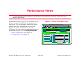
Performance views (Figure 9) are available for the
device, its ports, the modules it manages, and
their ports. The performance views listed below
provide statistical information such as load,
frame rate, errors, collisions, etc. For the
definitions for these statistics and a description of
performance views, refer to SPECTRUM Views.
Figure 9:
Device Performance View
þýüûúùø÷öõôóòÿñôÿõððùüïïîñôÿöøíúìëê
ÿ
Name
Contact
Description
Location
System Up Time
Network Address
Manufacturer
Device Type
Primary Application
Serial Number
• Device Performance View (Page 31)
100.0
10.00
1.00
0.10
Average
NOW
Log
• IF Performance View (Page 31)
Peak Value
* Frame Rate
%Delivered
%Forwarded
%Transmit
0.01
0
0:40:0 0:30:0 0:20:0
0
%Error
%Discarded
ÿ ù üïÿýüùÿïüûøëð
Graph Properties
SPECTRUM Enterprise Manager
P a g e 30
Scroll to Date-Time
Detail
SmartSwitch Router
Performance Views
Device Performance View
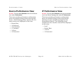
Device Performance View
IF Performance View
Access: From the Icon Subviews menu for the Device
Icon, select Performance.
Access: From the Icon Subviews menu for the Interface
icon in the Device Topology view, select IF Performance.
This view provides performance information
about the packets being passed through the
device. The following packet statistics for the
entire device are displayed in this view:
This view provides performance information
about the packets being passed through the
Interfaces on the modules managed by the
SmartSwitch Router. The following packet
statistics for the interface selected are displayed
in this view:
•
•
•
•
•
•
Frame Rate
% Delivered
% Forwarded
% Transmit
% Error
% Discarded
SPECTRUM Enterprise Manager
•
•
•
•
P a g e 31
Load
Packet Rate
% Error
% Discarded
SmartSwitch Router
Configuration Views
This section describes the various Configuration views and subviews available for models of SmartSwitch
Router devices in SPECTRUM.
Configuration views let you view and modify
current settings for the modeled device and its
interfaces, ports, and applications. The following
Configuration views are available for models of
SSR8000 and SSR8600 devices:
• Interface Configuration View
• Capacity Application Configuration View
(Page 33)
Interface Configuration View
Access: From the Icon Subviews menu for a selected
Interface icon in the Interface Device view, select Interface
Configuration
Figure 10 displays the Interface Configuration
view. Column headings are provided below for the
selected interface:
• SmartSwitch Router Configuration View
(Page 36)
• VRRP Configuration View (Page 40)
Figure 10:
Interface Configuration View
SpectroGRAPH: JK2
File
View
Tools
Bookmarks
Help
Interface Configuration View
Modelÿ
Contact
Description
Location
Operation Status
System Up Time
Network Address
Interface Type
Interface Index
IP Address/Network Mask
Physical Address
Admin. Status
Bandwidth
Last Change
Packet Size
Queue Length
SPECTRUM Enterprise Manager
P a g e 32
SmartSwitch Router
Configuration Views
Capacity Application Configuration View
Operation Status
The current operational state of the interface.
Valid values are: Up, Down, or Testing.
Interface Instance
The interface index number for this table.
Admin. Status
The desired operational state of the interface.
Valid values are: Up, Down, or Testing.
Capacity Application
Configuration View
Last Change
The System UpTime value when the interface
entered its current operational state.
Access: From the Icon Subviews menu for the
CapacityApp Application icon, select Configuration.
Slot Count
The maximum number of slots in the chassis,
including the slot for the CPU module.
Physical Address
The Ethernet (MAC) address of the interface.
Bandwidth
The estimated bandwidth of the interface,
measured in bits per second. For interfaces that
do not vary in bandwidth, or when no accurate
estimate can be made, a nominal bandwidth is
provided.
Packet Size
The largest packet that can be transmitted or
received by the port, displayed in octets.
Queue Length
The length of the outbound packet queue, in
packets.
Slots Used
The number of slots used in the chassis. This
number includes the slot used for the CPU
module, if any.
Slots Free
The number of free slots in the chassis. This
includes all of the available slots not used by the
CPU or redundant CPU card.
CPU Redundancy
The chassis CPU redundancy capability of the
SSR. Valid values are: noSupport, available,
enabled, and disabled.
Func Addr
Enables the IEEE Spanning Tree Protocol at the
TrBRF level to use the IBM bridge functional.
SPECTRUM Enterprise Manager
P a g e 33
SmartSwitch Router
Configuration Views
Capacity Application Configuration View
PS Redundancy
The chassis Power Supply redundancy capability
of the SSR. Valid values are: noSupport,
available, enabled, and disabled.
SF Redundancy
The chassis Switching Fabric redundancy
capability of the SSR. Valid values are:
noSupport, available, enabled, and disabled.
Memory Table
Clicking this button opens a table which displays
the storage devices in the SSR.
CPU Table
Clicking this button opens a table which displays
CPU statistics.
Task Table
A summary of the tasks running on a CPU
enabled module in the chassis. Column headings
are as follows:
Task
A unique index assigned to a task instance. This
index is unique to the task for the time SSR is
booted. If the task is terminated, the index will
not be reused for another task that might become
active in the system.
SPECTRUM Enterprise Manager
Name
The encrypted name assigned to this task. This is
unique for each different type of task, but there
may be multiple instances of the same task
running in the system.
Sched
The number of times this task has been
scheduled to run. This is a cumulative count from
the time the SSR was started.
Status
The current status of this task.
MemUsed
The size of the memory consumed by this task.
This can be used to monitor any excess memory
used by a particular task and is expressed in
bytes.
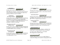
Capacity - Memory Table View
Access: From the Capacity Application Configuration
View, click on the Memory Table button.
A summary of the non-volatile storage devices in
the SSR. Column headings are as follows:
Index
An index or enumeration for the entries of a
particular memory type. This corresponds to:
• Interface index for L2Hardware Type
P a g e 34
SmartSwitch Router
Configuration Views
Capacity Application Configuration View
the number of times a Full Hash Bucket condition
has been met.
• Module index for L3Hardware Type
• Enumeration for everything else.
Description
The description of the memory device.
Size
Memory device total memory capacity expressed
in blocks.
Removable
Indicates if the memory type is removable. Valid
values are: yes and no.
Capacity - CPU Table View
Free
Device free memory in blocks. This will include
any unused memory between used memory
blocks and is calculated by subtracting the
memory used from the size of the memory device.
Access: From the Capacity Application Configuration
View, click on the CPU Table button.
Used
Size of used memory on the memory device. This
includes the blocks of memory that are only
partially used and is expressed in blocks.
Index
The slot index in which the current CPU is
residing.
BlockSize
Size of the memory blocks on the memory device.
This is the minimum block size of memory
returned when memory is requested and is
expressed in bytes.
Failures
The number of times a memory allocation in this
memory device has failed. In the case of
L2Hardware and L3Hardware types it expresses
SPECTRUM Enterprise Manager
Summary of CPU statistics. It is assumed that
there is only one CPU per line card.Index. Column
headings are as follows:
CurrUtil
The CPU utilization expressed as an integer
percentage. This is calculated over the last 5
seconds at a 0.1 second interval as an average.
L3Learned
The total number of new layer 3 (L3) flows the
CPU has processed and programmed into the L3
hardware flow tables. L3 flows are packets for IP
or IPX protocols that will be routed from one
subnet to another. Bridged flows or IP and IPX
P a g e 35
SmartSwitch Router
Configuration Views
SmartSwitch Router Configuration View
flows that originate and terminate in the same
subnet are accounted for by L2Learned.
L3Aged
The total number of L3 flows that have been
removed from the L3 hardware flow tables across
all modules by the L3 aging task. This number
may increase quickly if routing protocols are not
stable. Removal or insertion of routes into the
forwarding table will cause premature aging of
flows. Flows are normally aged/removed from the
hardware when there are no more packets being
sent for a defined time period. This counter is
cumulative from the time the system started.
L2Learned
The number of Layer 2 (L2) flows or addresses
learned. The intended result here is to see how
many stations attempt to establish switched
communication through the SSR.
NIA-txd
The total number of packets transmitted by the
NIA chip. This is useful in seeing how much the
CPU is communicating directory with
management stations and other routers.
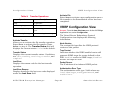
SmartSwitch Router
Configuration View
Access: From the Icon Subviews menu for the Device
icon, select Configuration.
Contact Status
The contact status of the model.
Number of Interfaces
The number of interfaces on the model.
Redundancy and Model
Reconfiguration Options
L2Aged
The total number of L2 addresses or flows aged
out. Hosts that end switched communication
through the SSR are aged out every 15 seconds.
Clicking this button opens the Redundancy and
Model Reconfiguration Options View (Page 37).
NIA-rcvd
The total number of packets received by the NIA
chip. This is useful in gauging how many packets
are forwarded to the CPU for processing.
Clicking this button opens the Interface Address
Translation Table (Page 39).
SPECTRUM Enterprise Manager
IP IF Address Translation
P a g e 36
SmartSwitch Router
Configuration Views
SmartSwitch Router Configuration View
Admin Status
The desired operational state of the interface.
Valid values are: Up, Down, or Testing.
TFTP Configuration
Clicking this button opens the SmartSwitch
Router TFTP View (Page 39).
Last Change
The System UpTime value when the interface
entered its current operational state.
Interface Configuration Table
This section provides the following information:
Queue Length
The length of the outbound packet queue, in
packets.
Description
Contains the name of the device and the
hardware revision number.
Type
The type of module plugged into the slot. Module
types OC8600 and OC860x(860x) represent the
mother board with the CPU and system memory.
Module state none represents a slot with no
modules plugged in.
Bandwidth
The estimated bandwidth of the interface,
measured in bits per second. For interfaces that
do not vary in bandwidth, or no accurate estimate
can be made, a nominal bandwidth is provided.
Physical Address
The Ethernet (MAC) address of the interface.
Packet Size
The largest packet that can be transmitted or
received by the port, displayed in octets.
Redundancy and Model
Reconfiguration Options View
Access: From the Icon Subviews menu for the Application
icon, select Rtr Redundancy.
This view allows you to enable redundant
addresses, have SPECTRUM notify you of a
redundancy update, and reconfigure aspects of
your network connections. Column headings are
as follows:
Operation Status
The current operational state of the interface.
Valid values are: Up, Down, or Testing.
SPECTRUM Enterprise Manager
P a g e 37
SmartSwitch Router
Configuration Views
SmartSwitch Router Configuration View
Redundancy
Administrative Status
Generate Redundancy
Alarms
Setting this button to Enabled will cause
SPECTRUM to display a redundant address from
the Redundant Preferred Address list when the
primary address is not accessible.
Setting this button to True will cause SPECTRUM
to generate an alarm when a redundant address
has been selected.
Create Sub Interfaces
Automatically
Reconfigure Interfaces
Setting this button to True will cause SPECTRUM
to monitor the number of interfaces for this
device. If a change is detected by SPECTRUM, the
interfaces displayed in SPECTRUM will be
updated to reflect the change.
Setting this button to True will cause SPECTRUM
to display sub-interfaces in the DevTop view when
RFC1573 is supported by the device.
Topologically Relocate
the Model
Setting this button to True will cause SPECTRUM
to relocate the model for this device to a different
topological location as part of AutoDiscovery.
Reconfigure due to LINK
UP/Down events
Setting this button to True will cause SPECTRUM
to verify the interfaces displayed when a LINK UP
or LINK DOWN event is received.
Device Discovery after
Reconfiguration
Setting this button to True will cause SPECTRUM
to verify the interfaces displayed after a model
reconfiguration occurs.
Button Explanations
Clicking this button will display a window that
allows you to read definitions for the buttons
included in the Redundancy and Model
Reconfiguration Options view.
Reconfigure Model
Clicking this button will cause SPECTRUM to
verify and change the interfaces displayed for this
SPECTRUM Enterprise Manager
P a g e 38
SmartSwitch Router
Configuration Views
device when necessary. If the Topologically
Relocate the Model button is set to True, this
button will also execute a device discovery.
Discover LANs
Clicking this button will cause SPECTRUM to
execute a device discovery on this devices
connections.
Interface Address Translation
Table
Access: From the SmartSwitch Router Configuration
view, click on the IP IF Address Translation button.
This table provides the physical and network
addresses associated with the interface index.
Interface Index
A pointer to the entry in the Interface Table
corresponding to this port.
Physical Address
The Ethernet (MAC) address of the interface.
SmartSwitch Router Configuration View
SmartSwitch Router TFTP View
Access: From the SmartSwitch Router Configuration
View, click on the TFTP Configuration button.
This view allows you to manage SmartSwitch
Router configuration files and perform file
transfers to and from the manager and agent.
Column headings are as follows:
Manager Address
Displays the address for the manager used by the
agent for CFG transfer operations. The value
0.0.0.0 is the default. The address must be a
unicast address that is reachable from the agent.
File Name
Displays the file name to be retrieved from the tftp
server at the host manager address or the file
name to be written to. The default is blank.
Transfer Operation
Displays the transfer operation to be performed.
Send and receive operations use tftp to transfer
files from the manager to the agent. Table 9 lists
possible operations:
Network Address
The IP Address of the interface.
SPECTRUM Enterprise Manager
P a g e 39
SmartSwitch Router
Configuration Views
Table 9:
VRRP Configuration View
Activate File
Enter True to activate a new configuration once a
file transfer to the SmartSwitch router has been
completed.
Transfer Operations
Operation
Description
noop
No operation.
sendConfigToAgent
Send configuration to agent.
receiveConfigFromAgent
Receive configuration from
agent.
VRRP Configuration View
receiveBootlogFromAgent Receive boot log from the agent.
Activate Transfer
Allows you to activate the file transfer operation.
Enter True to activate the file transfer. Enter
False to stop it. The Transfer Status field will
displays the current status. False is the default.
Access: From the Icon Subviews menu for the rfc2338App
Application icon, select Configuration.
The Virtual Router Redundancy Protocol
Configuration view displays the following
information:
Node Version
The version field specifies the VRRP protocol
version of this packet.
Transfer Status
Displays the current transfer status. Conditions
are: idle, sending, receiving, transfer, and
complete.
Trap Control
Indicates whether the VRRP-enabled router will
generate SNMP traps for events defined in this
MIB. Enabled results in SNMP traps; disabled
means no traps are sent.
Last Error
Displays the reason code for the last transfer
operation.
Packet Source
The IP address of an inbound VRRP packet.
Last Error Reason
Displays details for the last error code displayed
under the Last Error field.
Authorisation Error Type
The authorization error type. Valid values are:
InvalidAuthtype, authTypeMismatch, and
authFailure.
SPECTRUM Enterprise Manager
P a g e 40
SmartSwitch Router
Configuration Views
VRRP Configuration View
VRRP Operations Table
Table 10:
Virtual Router States
This table provides the following information:
State
Index
This field contains the Virtual Router Identifier
(VRID).
Virt MAC Address
The virtual MAC address of the virtual router.
This is derived as follows: 00-00-5E-00-01<VRID>.
Where the first three octets consist of the IANA’s
OUI; the next two octets indicate the address
block of the VRRP protocol; and the remaining
octets consist of the VRID.
State
The mandatory state of the virtual router. This
field has three defined values, as described in
Table 10:
Description
initialize
The virtual router is waiting for is
startup event.
backup
The virtual router is monitoring
the availability of the master
router.
master
The virtual router is forwarding
packets for IP addresses that are
associated with this router.
Setting the Admin State (below) initiates
transitions in the value of this field.
Admin State
This field will enable/disable the virtual router
function. Setting the value to up, will transition
the State of the virtual router from “initialize’” to
“backup” or “master”; setting the value to down,
will transition the router from “master” or
“backup” to “initialize”. State transitions may not
be immediate; they sometimes depend on other
factors, such as the interface (IF) state.
This field must be set to down prior to modifying
the other read-write fields in the conceptual row.
The value of Status (Page 43) must be “active”,
signifying that the conceptual row is valid (i.e.,
SPECTRUM Enterprise Manager
P a g e 41
SmartSwitch Router
Configuration Views
VRRP Configuration View
the fields are correctly set), in order for this field
to be set to up.
Pri
The priority to be used for the virtual router
master election process. Higher values imply
higher priority.
A priority of 0, although not settable, is sent by
the master router to indicate that this router has
ceased to participate in VRRP and a backup
virtual router should transition to become a new
master.
A priority of 255 is used for the router that owns
the associated IP address(es). The default value is
100.
IP Addr Cnt
The number of IP addresses that are associated
with this virtual router. This number is equal to
the number of rows in the vrrpAssoIpAddrTable
that correspond to a given IF index/VRID pair.
Auth Type
Authentication type used for VRRP protocol
exchanges between virtual routers. This value of
this field is the same for a given Index. Valid
values are described in Table 11:
Table 11:
Authentication Types
Authentication Type
Master IP Addr
The master router’s real (primary) IP address.
This is the IP address listed as the source in
VRRP advertisement last received by this virtual
router.
SPECTRUM Enterprise Manager
Primary IP Addr
In the case where there is more than one IP
address for a given Index, this field is used to
specify the IP address that will become the
Master IP Addr, should the virtual router
transition from backup to master. If this field is
set to 0.0.0.0, the IP address which is
numerically lowest will be selected.
Description
noAuthentication
VRRP protocol exchanges are
not authenticated.
simpleTextPassword
Exchanges are authenticated
by a clear text password.
ipAuthenticationHeader Exchanges are authenticated
using the IP authentication
header.
P a g e 42
SmartSwitch Router
Configuration Views
VRRP Configuration View
Auth Key
The Authentication Key. This field is set according
to the value of Auth Type (“simpleTextPassword”
or “ipAuthenticationHeader”). If the length of the
value is less than 16 octets, the agent will left
adjust and zero fill to 16 octets. The value of this
field is the same for a given ifIndex.
When read, this value always returns an Octet
String of length zero.
Adv Intvl
The time interval, in seconds, between sending
advertisement messages. Only the master router
sends VRRP advertisements. The default is 1
second.
Preempt Mode
Controls whether a higher priority virtual router
will preempt a lower priority master. Default is
True.
Up Time
This is the value of the “sysUpTime” field when
this virtual router (i.e., the State) transitioned out
of “initialized.”
Status
The row status variable, used in accordance to
installation and removal conventions for
conceptual rows.
The state that this field transitions to when set is
based on a determination of whether the readwrite fields in the row have been correctly
initialized for virtual router operation. A row in
which not all of the fields are correctly set is
considered ‘incomplete’.
The row status of a mandatory active row in the
vrrpOperTable is also constrained by the
operational state of the corresponding virtual
router. Prior to setting this field from active to a
different value, Admin State must be set to
“down”, and the State field be transitioned to
“initialize.”
The row status column has six defined values, as
defined in Table 12:
Protocol
The particular protocol being controlled by this
Virtual Router. Valid values are: ip, bridge,
decnet, and other.
SPECTRUM Enterprise Manager
P a g e 43
SmartSwitch Router
Configuration Views
Table 12:
Row Status
active
(read/set)
VRRP Configuration View
Table 12:
Row Status
Row Status
Description
When this value is read, it indicates that
all the read-write fields (in the row)
required for virtual router operation
have been correctly initialized such that
the respective virtual router can be
made operational by setting the Admin
State to “up”. When set to active, no
other fields in the conceptual row, with
the exception of Admin State, can be
modified.
When set, the agent will transition the
value of rowstatus to ‘notReady’ if the
row is incomplete.
notInService
(read/set)
When set, allows the fields in the row to
be modified by a management station,
thus changing the operational
characteristics of the corresponding
virtual router.
notReady
(read)
The agent sets the field to this state to
indicate that the conceptual row exists,
but is lacking initialization of one or
more fields required for virtual router
operation.
SPECTRUM Enterprise Manager
Row Status
Description
createAndGo
(set)
Set by a management station wishing to
create a new instance of a virtual router
and to have its status automatically set
to active, making it available for use by
a virtual router. Upon receiving a
request to set the row status to this
value, the agent transitions the
rowstatus to active if the other settable
fields in the row have been correctly
initialized. If the row is incomplete, the
agent transitions the state to notReady.
createAndWait
(set)
Set by a management station wishing to
create a new instance of a virtual router
but not make it available for use. When
this value is set, rowstatus transitions to
notInService if the row has been
correctly initialized; if the row is
incomplete, row status will become
notReady.
destroy
(set)
Deletes the conceptual row, and hence,
the corresponding instance of a virtual
router.
P a g e 44
SmartSwitch Router
Core Watch Application
The Core Watch application allows you to access information for the chassis and the line modules it contains.
CoreWatch is a device management and
configuration application for SmartSwitch
Routers. It provides configuration, monitoring,
and reporting capabilities with the assistance of
wizards, property sheets, and drag-and-drop
operations. CoreWatch provides access to
Configuration Expert, which is a utility that
makes it easier to configure routers, virtual local
area networks (VLANs), application-level Quality
of Service (QoS) policies, and security filters.
CoreWatch management features include:
fields, assign a precedence to the fields of the
flows you define, and establish queuing
policies.
• Configuration of security filters and access
control lists (ACLs). An ACL is a list the SSR
keeps to control access to or from various
services.
• Drag-and-drop VLAN setup and
administration.
• Detailed reporting in the hypertext markup
language (HTML) format.
• Java-based graphical user interface (GUI).
• For more detailed information on using Core
Watch, refer to the Core Watch User’s Guide.
• Simplified bridging configuration.
• Simplified routing configuration.
• Quality of Service (QoS) policy management.
• QoS is a set of parameters that assign
priorities to different types of traffic, define
flows for Internet Protocol (IP) and
Internetwork Packet Exchange (IPX) packet
SPECTRUM Enterprise Manager
P a g e 45
SmartSwitch Router
Model Information View
This section provides a brief overview of the Model Information view.
This view displays administrative information
about the device and its applications and lets you
set thresholds and alarm severity for the device.
Figure 11 shows a sample Model Information
view. The layout of this view is the same for all
model types in SPECTRUM but some information
will vary depending on the model it defines. Refer
to the SPECTRUM Views documentation for a
complete description of this view.
Figure 11:
Model Information View
SpectroGRAPH: IP Address
File
View
Tools
Help
Bookmarks
Model Information View
Model Name
Contact
Network Address
System Up Time
Manufacturer
Description
Location
User-Defined Type
Device Type
Primary Application
Primary Address
General Information
MM Name
Serial Number
Communication Information
DCM Timeout
MM Part Number
DCM Retry
MM Version Number
Community Name
Model Type
Mgmt Protocol
Model Creation Time
Model Created By
Model State
Security String
Condition
Poll/Log Information
Poll Interval
Polling Status
Last Successful Poll
Log Ratio
Condition Value
Contact Status
Lost Child Count
LOGGED
POLLED
Value When Yellow
Value When Orange
Value When Red
SPECTRUM Enterprise Manager
P a g e 46
SmartSwitch Router
50
Index
Symbols
B
%
%
%
%
%
Bandwidth 33, 37
BGP 26
BlockSize 35
Board Detail 16
BRF Configuration View 33
Delivered 31
Discarded 31
Error 31
Forwarded 31
Transmitted 31
Numerics
C
6_SSRM_02 8
Capacity - CPU Table View 35
Capacity - Memory Table View 34
Chassis Device View 14
Chassis ID 24
Chassis Module Icon 10
Module Notes 16
Chassis Views
Environment View 24
Module Hardware View 23
Port Hardware View 24
Service Status View 26
Colors
Interface Status Label 13
Configuration View
Device
Activate File 40
Activate Transfer 40
A
Acitvate File 40
Activate Transfer 40
Address Translation Table 14
Admin. Status 33
Administrative Status 14
administrative status 13, 17
Administrative Status Label 12
Application
Device-specific 23
Application View 21
Automatically Reconfigure
Interfaces 38
SPECTRUM Enterprise Manager
Page 47
File Name 39
Last Error 40
Last Error Reason 40
Manager Address 39
Transfer Operation 39
Transfer Status 40
Configuration views 32
Connector Type 24
Contact Status 36
Control Module 7, 25
CPU Redundancy 33
Create Sub Interfaces 38
Current Utilization 35
D
Delivered 31
Device Discovery after
Reconfiguration 38
Device Topology View 19
Discarded 31
Discover LANs 39
DVMRP 26
SmartSwitch Router
Index
E
Environment View
Chassis ID 24
Fan 24
Num Slots 24
Temperature 24
Error 31
F
Failures 35
Fan 24
File Name 39
Forwarded 31
Frames Received Rate 31
Free 35
G
Generate Redundancy Alarms 38
I
Icon
Chassis Module 15
Ethernet Chassis Module 16
Interface 12
Icon Subviews Menu
Index
Chassis Module 16
Interface Label 13, 17
Icons
Interface 19
IF Index 24
IGMP 26
Interface Address Translation
Table 39
Interface Configuration View 32
Interface Device View 11
Interface Icon
Administrative Status 14
Operational Status 14
Interface Index 39
Interface Labels 15
Interface Menu Selection
IF Confirguration 13, 17
IF Details 13, 17
IF Performance 17
IF Status 13, 17
IF Thresholds 14, 17
Model Information 14, 17
Network Information Panel 17
Interface Number Label 12
Interface Status Label 15
Interface Type Label 15
IP Address Label 13
IPX RIP 26
IPX SAP 26
SPECTRUM Enterprise Manager
Page 48
L
L2Aged 36
L2Learned 36
L3Aged 36
L3Learned 35
Labels
Interface
Physical Address Label 13
Last Change 33
Last Error 40
Last Error Reason 40
Last Hot Swap 24
LFAP 26
line modules 7
Load 31
M
Manager Address 32
Memory Used 34
Model Type Label 15
Module 23, 24
Module Hardware View 23
Module 23
Num Ports 23
Version 23
Module Hareware View
Description 23
Module Identification Labels 15
Module Notes 16
SmartSwitch Router
Index
N
Index
Network Address 39
Network I/O ports 19
NIA-received 36
NIA-transmitted 36
Num Slots 26
Number of Interfaces 36
IF Index 24
Module 24
Port 24
Port Type 24
Port Type 24
Power Supply 25
Power Supply Status Indicator 25
PS Redundancy 34
O
Q
Operation Status 33
Operational Status 14
operational status 13, 17
OSPF 26
Queue Length 33, 37
P
Packet Rate 31
Packet Size 33, 37
Physical Address 33, 37, 39
Physical Device View 11
PIM 26
Port 24
disable 13, 17
enable 13, 17
off 13, 17
on 13, 17
Port Hardware View 24
Connector Type 24
R
Reconfigure due to LINK UP/Down
events 38
Reconfigure Model 38
Redundancy Administrative
Status 38
Redundancy and Model
Reconfiguration Options
View 37
Removable 35
Restricted Rights Notice 2
RIP 26
SPECTRUM Enterprise Manager
S
Secondary Address Panel 14
Serial ports 19
Service Status View 26
BGP 26
DVMRP 26
IGMP 26
IPX RIP 26
IPX SAP 26
OSPF 26
PIM 26
RIP 26
STP 26
SF Redundancy 34
Slot Count 33
Slot Number Label 15
Slots Free 33
Slots Used 33
SmartSwitch Router TFTP View 39
SmartSwRtr 8
SmartSwRtr32 8
SSR_ChassApp 23
Status 34
Adminstrative 12
STP 26
Switch Fabric Alarm Watch 25
T
Task 34
Page 49
SmartSwitch Router
Index
Index
Task Table 34
Temperature 24
Topologically Relocate the Model 38
Trademarks 2
Transfer Operation 39
Transfer Status 40
Transmit 31
U
Used 35
V
Version 23
Views
Application 21
Configuration 32
Device Icon 10
W
Watch Manager 25
SPECTRUM Enterprise Manager
Page 50
SmartSwitch Router