1
A008
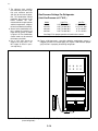
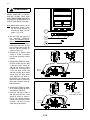
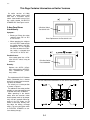
Component Location and
Identification (Single Door
Models)
A. Illuminated Ignition Switch
B. Flame On Indicator Lamp
C. Thermostat Control Knob
D. Combination Control Knob
1. Gas On/Electric Interlock
2. Push-In Safety Valve
E. AC/DC Mode Selector Switch
(3-Way models only)
F. Serial Identification Plate
F
A
Figure 3.2
B
C
D
E
Controls Location, Single Door Model
G
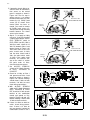
Component Location and
Identification (Two Door
Models)
A. Illuminated Ignition Switch
B. Flame On Indicator Lamp
C. Thermostat Control Knob
D. Combination Control Knob
1. Gas On/Electric Interlock
2. Push-in Safety Valve
E. AC/DC Mode Selector Switch
(3-Way models only)
F. Serial Identification Plate
G. Three Position Switch (See
page 3-6)
1. NORMAL
2. STORAGE
3. HIGH HUMIDITY
H. Interior Light Switch
F
A
Figure 3.3
B
Controls Location, Two Door Model
3-4
C
D
E
H