1
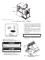
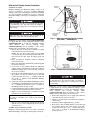
48/50HG014-028, 48/50PG03-28
Single-Package Rooftop Units
Enthalpy Switch Accessory and
Differential Enthalpy Control Accessory
for use with COMFORTLINK™ Controls
Installation Instructions
Part Numbers CRENTSNG002A00 (Enthalpy Switch)
CRENTDIF002A00 (Differential Enthalpy Control)
PACKAGE CONTENTS — CRENTSNG002A00
ITEM
Enthalpy Switch (Part No. HH57ZC003)
No. 10AB, 1/2-in. long Sheet Metal Screw
QUANTITY
1
2
PACKAGE CONTENTS — CRENTDIF002A00
ITEM
Differential Enthalpy Control
(Part No. HH57ZC001)
Red Wire Assembly (35-in. long)
Black Wire Assembly (35-in. long)
Grommet (Part No. KA56GR140)
No. 8,18, 1/2-in. long Sheet Metal Screw
QUANTITY
INSTALLATION
Enthalpy Switch Installation
48/50PG03-16 UNITS
NOTE: If installing the enthalpy switch on an accessory economizer, it is easier to install the enthalpy sensor prior to installing the economizer. If installing on a factory-installed
economizer, it is easier to install the enthalpy sensor prior to
installing the economizer hoods.
1
1
1
1
2
Prior to installation of this accessory, make sure all power
is disconnected to the unit and locked out. Failure to
disconnect power supply prior to servicing may result in
serious injury.
GENERAL
If single, outdoor-air enthalpy control is desired, a single
enthalpy control must be installed in these units.
The accessory enthalpy switch maximizes the use of free
outdoor air for efficient economizer operation with 48/50HG
and 48/50PG rooftop units. It works with the outdoor-air sensor
to determine when the economizer can be used for cooling.
Differential enthalpy control is used to increase the operating efficiency of the rooftop system. The system compares the
temperature and humidity of the return air to that of the outdoor
air to determine whether outdoor air or mechanical cooling is
more economical and efficient. The accessory enthalpy switch
(CRENTSNG002A00) is required with the accessory differential enthalpy control (CRENTDIF002A00) to provide the differential enthalpy control function.
NOTE: Use of the differential enthalpy control accessory
requires
that
the
accessory
enthalpy
switch
(CRENTSNG002A00) is installed to sense outdoor enthalpy
and to provide input to the control system.
SAFETY CONSIDERATIONS
Installation and servicing of air-conditioning equipment can
be hazardous due to system pressure and electrical components. Only trained and qualified service personnel should
install, repair, or service air-conditioning equipment.
Untrained personnel can perform the basic maintenance
functions of replacing filters. All other operations should be
performed by trained service personnel. When working on airconditioning equipment, observe precautions in the literature,
tags and labels attached to the unit, and other safety precautions
that may apply.
When removing panels from the unit, be careful not to
damage the roof or other surfaces with the panels.
1. Remove the screws securing the economizer hood panel
to the unit. Save the screws for use later.
NOTE: On size 03-14 units with factory-installed economizers, the panel will be hinged and should not be removed from the unit. Open the hinged panel and secure.
2. Mount the enthalpy switch to the economizer frame as
shown in Fig. 1, using the two screws provided.
3. From the unit harness assembly, locate the three enthalpy
wires (red, brown, and pink). Connect the red wire to
terminal 24VAC on the enthalpy switch. Connect the
brown wire to terminal GND on the enthalpy switch.
Connect the pink wire to terminal LOW on the enthalpy
switch. See Fig. 2.
4. If the accessory differential enthalpy control is also being
installed, install the accessory instead of performing the
following steps. See Differential Enthalpy Control Installation section on page 3.
5. Replace (or close if hinged panel) the economizer panel
using the screws saved from Step 1.
IMPORTANT: Be sure all seal strips and RTV sealant
are intact. A watertight seal to inside of unit must be
maintained.
6. Restore power to the unit and configure the unit for use
with the accessory. See Configuring the Control System
section on page 5.
Manufacturer reserves the right to discontinue, or change at any time, specifications or designs without notice and without incurring obligations.
PC 111
Catalog No. 534-80217
Printed in U.S.A.
Form 48/50H,P-3SI
Pg 1
3-05
Replaces: New
Book 1 1 4 4
Tab 1a 1b 6a 6b
PLUG BUTTON
ENTHALPY
SWITCH
NOTE: Vertical economizer is shown.
Fig. 1 — Enthalpy Switch Installation — 48/50PG03-16
3. From the unit harness assembly, locate the three enthalpy
wires (red, brown, and pink). Connect the red wire to
terminal 24VAC on the enthalpy switch. Connect the
brown wire to terminal GND on the enthalpy switch.
Connect the pink wire to terminal LOW on the enthalpy
switch. See Fig. 2.
4. If the accessory differential enthalpy control is also being
installed, install the accessory instead of performing the
following steps. See Differential Enthalpy Control Installation section on page 3.
5. Replace the damper motor access panel using the screws
saved from Step 1.
IMPORTANT: Be sure all seal strips and RTV sealant
are intact. A watertight seal to inside of unit must be
maintained.
Fig. 2 — Enthalpy Switch Details
6. Restore power to the unit and configure the unit for use
with the accessory. See Configuring the Control System
section on page 5.
48/50HG AND 48/50PG20-28 UNITS
NOTE: For horizontal applications it is easiest to install the
enthalpy sensor prior to making duct connections.
Prior to installation of this accessory, make sure all power
is disconnected to the unit and locked out. Failure to
disconnect power supply prior to servicing may result in
serious injury.
HARNESS
WIRES
ENTHALPY
SWITCH
When removing panels from the unit, be careful not to
damage the roof or other surfaces with the panels.
1. Remove the damper motor access panel at the return end
of the unit. Save the screws for use later.
2. Mount the enthalpy switch to the economizer frame as
shown in Fig. 3, using the two screws provided.
Fig. 3 — Switch Installation — 48/50HG and
48/50PG20-28 Units
2
Differential Enthalpy Control Installation
ENTHAPLY
SWITCH
48/50PG03-16 UNITS
NOTE: If installing the differential enthalpy control on an
accessory economizer, it is easier to install the differential
enthalpy control prior to installing the economizer. If installing
on a factory-installed economizer, it is easier to install the
differential enthalpy control prior to installing the economizer
hoods.
Prior to installation of this accessory, make sure all power
is disconnected to the unit and locked out. Failure to
disconnect power supply prior to servicing may result in
serious injury.
DIFFERENTIAL
ENTHAPLY
CONTROL
When removing panels from the unit, be careful not to
damage the roof or other surfaces with the panels.
Fig. 4 — Differential Enthalpy Control Location
(Side View) — 48/50PG03-16
NOTE: The accessory enthalpy switch (CRENTSNG002A00)
is required with the accessory differential enthalpy control
(CRENTDIF002A00) to provide the differential enthalpy
control function. The accessory enthalpy switch
(CRENTSNG002A00) must be installed to sense outdoor
enthalpy and to provide input to the control system.
1. Remove the screws securing the economizer hood panel
to the unit. Save the screws for use later.
NOTE: On size 03-14 units with factory-installed
economizers, the panel will be hinged and should not be
removed from the unit. Open the hinged panel and
secure.
2. If the economizer is installed, it must be completely
removed at this time.
3. Remove the plug button and install the grommet supplied
into the hole. See Fig. 1.
4. Locate holes in the partition. Mount the differential
enthalpy control on the back side of the partition directly
behind the enthalpy switch as shown in Fig. 4 using the
No. 8 screws provided.
5. Route the two wires included with the accessory through
the grommet and into the return section of the unit.
Connect the black wire to the “–” terminal and the red
wire to the “+” terminal on the Differential Enthalpy
Control. See Fig. 5.
6. Connect the wires from the Differential Enthalpy Control
to the Enthalpy Switch. The black wire should connect to
the “–” terminal and the red wire to the “+” terminal on
the Enthalpy Switch. See Fig. 2 and 6.
7. Complete installation of the economizer. If the economizer was previously installed, reinstall the economizer.
8. Replace (or close if hinged) the economizer hood panel
using the screws saved from Step 1.
Fig. 5 — Differential Enthalpy Control Details
Prior to installation of this accessory, make sure all power
is disconnected to the unit and locked out. Failure to
disconnect power supply prior to servicing may result in
serious injury.
NOTE: The accessory enthalpy switch (CRENTSNG002A00)
is required with the accessory differential enthalpy control
(CRENTDIF002A00) to provide the differential enthalpy
control function. The accessory enthalpy switch
(CRENTSNG002A00) must be installed to sense outdoor
enthalpy and to provide input to the control system.
1. Remove the damper motor access panel at the return end
of the unit. Save the screws for use later.
2. Punch a 7/8-in. hole in the economizer block-off panel as
shown in Fig. 7.
3. Install the grommet supplied into the 7/8-in. hole.
4. Route the two wires included with the accessory through
the grommet and into the return section of the unit.
Connect the black wire to the “–” terminal and the red
wire to the “+” terminal on the Differential Enthalpy
Control. See Fig. 5.
IMPORTANT: Be sure all seal strips and RTV sealant
are intact. A watertight seal to inside of unit must be
maintained.
9. Restore power to the unit and configure the unit for use
with the accessory. See Configuring the Control System
section on page 5.
48/50HG AND 48/50PG20-28 UNITS
NOTE: For horizontal applications it is easiest to install the
differential enthalpy control prior to making duct connections.
3
5. Locate holes on the economizer frame. Mount the differential enthalpy control as shown in Fig. 7 using the No. 8
screws provided.
6. Connect the wires from the Differential Enthalpy Control
to the Enthalpy Switch. The black wire should connect to
the “–” terminal and the red wire to the “+” terminal on
the Enthalpy Switch. See Fig. 2 and 6.
7. Replace the damper motor access panel using the screws
saved from Step 1.
IMPORTANT: Be sure all seal strips and RTV sealant
are intact. A watertight seal to inside of unit must be
maintained.
8. Restore power to the unit and configure unit for use with
the accessory. See Configuring the Control System
section on page 5.
UNIT
HARNESS
ASSEMBLY
BLK
RED
BROWN
PINK
RED
DIFFERENTIAL ENTHALPY CONTROL
ACCESSORY
ENTHALPY SWITCH ACCESSORY
Fig. 6 — Accessory Wiring
HARNESS
WIRES
ENTHALPY
SWITCH
GROMMET
DIFFERENTIAL
ENTHALPY
CONTROL
BLOCK-OFF PANEL
Fig. 7 — Differential Enthalpy Control Location — 48/50HG and 48/50PG20-28
4
Configuring the ComfortLink Control 48/50PG
Units) — The ComfortLink control must be configured to
CONFIGURING THE CONTROL SYSTEM
Configuring the ComfortLink™ Control (48/
50HG Units) — The ComfortLink control must be config-
use the enthalpy control. These configurations are changed
through the Scrolling Marquee display or a Carrier Comfort
Network device.
NOTE: Consult the Controls, Start-Up, Operation, Service and
Troubleshooting Instructions for in-depth instructions on using
and configuring the ComfortLink control. The following
instructions are written for the Scrolling Marquee display or
Navigator accessory.
1. The ComfortLink control must be configured to use the
economizer accessory. A password may be required to
edit the configurations depending on previous settings
configured in the unit. Default password is “1111”.
2. To configure the ComfortLink control, use the arrow
keys to scroll the red LED on the display to the
“Configuration” position and press ENTER .
ured to use the enthalpy control. These configurations are
changed through the Scrolling Marquee display or a Carrier
Comfort Network device.
NOTE: Consult the Controls, Start-Up, Operation, Service and
Troubleshooting Instructions for in-depth instructions on using
and configuring the ComfortLink control. The following
instructions are written for the Scrolling Marquee display or
Navigator™ accessory.
1. The ComfortLink control must be configured to use the
economizer accessory. A password may be required to
edit the configurations depending on previous settings
configured in the unit. Default password is “1111”.
2. To configure the ComfortLink control, use the arrow
keys to scroll the red LED on the display to the
“Configuration” position and press ENTER .
3. Use the arrow keys to scroll down until the display shows
“ECON”. This is the Economizer Configuration sub
menu. Press ENTER .
3. Use the arrow keys to scroll down until the display shows
“ECON”. This is the Economizer Configuration sub
menu. Press ENTER .
4. The control will display the Economizer Installed
(Configuration→ECON→EC.EN) setting. Use the
arrow keys to scroll down until the display shows
“EN.SW”. This is the enthalpy switch configuration.
Press ENTER once to select the Configuration→
ECON→EN.SW setting for configuration. Press
ENTER again for “0” to begin flashing.
4. The control will display the Economizer Installed
(Configuration→ECON→EC.EQ) setting. Use the
arrow keys to scroll down until the display shows
“EN.SW”. This is the enthalpy switch configuration.
Press ENTER once to select the Configuration→
ECON→EN.SW setting for configuration. Press
ENTER again for “0” to begin flashing.
5. Use the arrow keys to change the configuration to “1” for
a normally open switch. The Carrier accessory and wiring
is shown for normally open. Change the configuration to
“2” if using a normally closed switch. Then press
ENTER and ESCAPE to save the setting.
5. Use the arrow keys to change the configuration to “1” for
a normally open switch. The Carrier accessory and wiring
is shown for normally open. Change the configuration to
“2” if using a normally closed switch. Then press
ENTER and ESCAPE to save the setting.
6. For economizer cooling to occur, the enthalpy sensor
must sense “LOW” enthalpy and the outdoor-air temperature (Temperatures→AIR.T→OAT), as measured by
the unit control sensor, must be lower than the Economizer Cooling High Temperature Limit (EH.LO) and higher
than the Economizer Cooling Low Temperature Limit
(EL.LO). The values of EH.LO and EL.LO may be
viewed and changed in the Configuration→ECON submenu or in the Setpoints main menu.
7. If additional economizer control accessories have been
added or other configuration parameters are to be
changed from the factory defaults, then repeat the following steps:
a. Use the arrow keys to scroll up or down to the
parameter to change. Press ENTER once to select
the setting for configuration.
6. For economizer cooling to occur, the enthalpy sensor
must sense “LOW” enthalpy and the outdoor-air temperature (Temperatures→AIR.T→OAT), as measured by
the unit control sensor, must be lower than the Economizer Cooling High Temperature Limit (ECL.H) and higher
than the Economizer Cooling Low Temperature Limit
(ECL.L). The values of ECL.H and ECL.L may be
viewed and changed in the Configuration→ECON
submenu.
7. If additional economizer control accessories have been
added or other configuration parameters are to be
changed from the factory defaults, then repeat the following steps:
a. Use the arrow keys to scroll up or down to the
parameter to change. Press ENTER once to select
the setting for configuration.
b. Press ENTER again. The configuration value will
flash.
b. Press ENTER again. The configuration value will
flash.
c. Use the arrow keys to change the configuration
value.
d. Press ENTER and ESCAPE to save the setting.
8. Configuration of the ComfortLink control is now complete. Pressing ESCAPE multiple times will return the
display to the auto-scrolling setting.
c. Use the arrow keys to change the configuration
value.
d. Press ENTER and ESCAPE to save the setting.
8. Configuration of the ComfortLink control is now complete. Pressing ESCAPE multiple times will return the
display to the auto-scrolling setting.
9. The status of the enthalpy switch is accessible by viewing
the ENTH input located in the Input→GEN.I submenu
or the Run Status→ECON submenu.
10. Close and secure all access doors.
9. The status of the enthalpy switch is accessible by viewing
the ENTH input located in the Input→SW.IN submenu.
10. Close and secure all access doors.
5
Copyright 2005 Carrier Corporation
Manufacturer reserves the right to discontinue, or change at any time, specifications or designs without notice and without incurring obligations.
PC 111
Catalog No. 534-80217
Printed in U.S.A.
Form 48/50H,P-3SI
Pg 8
3-05
Replaces: New
Book 1 1 4 4
Tab 1a 1b 6a 6b