1
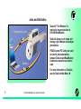
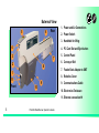
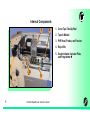
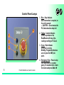
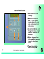
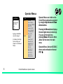
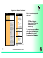
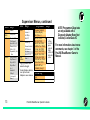
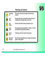
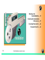
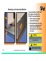
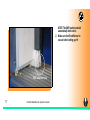
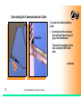
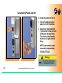
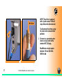
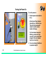
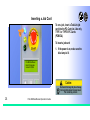
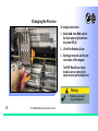
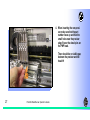
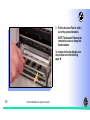
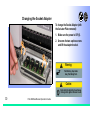
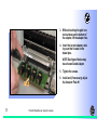
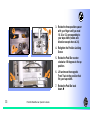
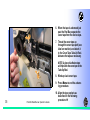
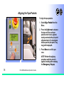
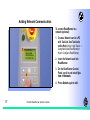
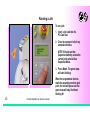
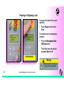
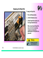
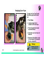
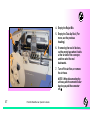
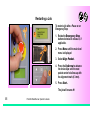
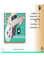
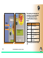
CONTENTS PN 096-0440-001A English Overview ProLINE-RoadRunner™ Operator’s Guide for Siemens SIPLACE X-Series* page 1 Installation 15 Job Setup 23 Operation 39 Maintenance 49 Troubleshooting 53 Index Data I/O has endeavored to ensure that the information in this document is accurate and complete. Data I/O assumes no liability for errors, or for any incidental, consequential, indirect, or special damages, including, without limitation, loss of use, loss or alteration of data, delays, or lost profits or savings, arising from the use of this document or the product which it accompanies. No part of this document may be reproduced or transmitted in any form or by any means, electronic or mechanical, for any purpose, without written permission from Data I/O. Data I/O is a registered trademark of Data I/O Corporation. ProLINE‐RoadRunner and TaskLink are trademarks of Data I/O Corporation. Data I/O Corporation acknowledges the trademarks of other organizations for their respective products or services mentioned in this document. SIPLACE is a registered trademark of the Siemens Corporation. © 2010 Data I/O Corporation All rights reserved *from front cover: supports some feeder table positions only. See Owner’s Manual, or contact Data I/O Customer Support. Chapter 1 ProLINE-RoadRunner for Siemens SIPLACE X........... 2 Jobs and Statistics........... 3 External View........... 4 Internal Components........... 5 Control Panel Lamps........... 6 Control Panel Buttons........... 7 Overview Operator Menus........... 8 Changing the Pass Limit........... 9 Supervisor Menus........... 10 Warnings and Cautions......... 14 Technical Support......... 63 1 ProLINE-RoadRunner Operator’s Guide A The ProLINE-RoadRunner for Siemens X 3 4 2 Data I/O is proud to introduce an inline solution for high-volume programming of electronic products. ProLINE-RoadRunner: 1. Takes programmable devices from a reel... 1 2. Places them in sockets and programs them with your data... 3. Places them on a conveyor belt... 4. Delivers them to the pick point of your assembly machine. 2 ProLINE-RoadRunner Operator’s Guide A Jobs and Statistics Programming Jobs TaskLink™ for Windows is required to process devices on ProLINE-RoadRunner. TaskLink allows you to create and manage a job database and analyze job statistics. Statistics PCMCIA cards (PC-Cards) are used to transfer jobs and statistics between TaskLink and RoadRunner. A network connection can also be used. For more information on TaskLink, see the TaskLink Help Menu. 3 ProLINE-RoadRunner Operator’s Guide A External View 5 6 Rear 1. Power and Air Connections 2. Power Switch 3. Handhold for lifting 4 4. PC Card Slot and Eject button 3 7 2 8 1 11 Front 5. Control Panel 6. Conveyor Belt 7. Feeder Bank Adapter to SMT 8. Robotics Cover 9 10 9. Communications Cable 10. Electronics Enclosure 11. Ethernet connection 4 ProLINE-RoadRunner Operator’s Guide A Internal Components 3 4 1. Cover Tape Take-Up Reel 2. Tape-In Module 3. PNP Head, Probes, and Precisor 4. Reject Bin 5. Socket Adapter, Actuator Plate, and Programmer 1 2 5 5 ProLINE-RoadRunner Operator’s Guide A Control Panel Lamps 4 2. Yellow - Caution Indicator. Correct a problem or the RoadRunner will stop. Also, reading or writing to PC-Card. 1 2 3. Green - Run Indicator. Lit: A job is running. Blinking: Programmed devices are not yet at the SMT pick point. 3 6 1. Blue - Stop Indicator. User intervention is required, or the unit is paused. — CAUTION — Do not remove the PC-Card unless blue lamp is lit. ProLINE-RoadRunner Operator’s Guide A 4. Emergency Stop - Press to stop the robot motors in an emergency. To resume motion, rotate the button and press Start. Control Panel Buttons 2 1 1. Start - start or resume the chosen job. 2. Menu - exit to the previous menu, —or show the next message (deleting the current one), —or deselect an item to end a process. 3 3. Up and Down Arrows - scroll through menu items, —or toggle selections, —or advance the device tape. 4 5 4. Select - select menu items. In this guide, Select Job means to scroll to Job and press Select. 5. Pause - interrupt the job without cancelling it. 7 ProLINE-RoadRunner Operator’s Guide A Operator Menus M a in M e n u Job Job Advance Pocket Align Pocket Purge Socket View • Light gray shaded fields cannot be changed. • For Advance Pocket, Align Pocket, and Purge, see Chapter 3 in the Owner’s Manual. 8 Results Job Name Device: E28F320 Checksum: 3FC00000 Mfg: INTEL Adapter: PA-G021 Prec: 621-0086-005 Act: 644-0016-001 Encrypted: No Passed: 992 Failed: 4 System Yld: 98.7 Prgrmr Yld: 99.6 Handler Yld: 99.5 Parts/Hour: 255 MCBI: 201 Skt 1 Yld: 99.9 Skt 2 Yld: 100 Skt 3 Yld: 100 Skt 4 Yld: 100 Skt Cycles: 249 ProLINE-RoadRunner Operator’s Guide A Operator Menus are visible on the Control Panel, and can be navigated by using the Up Arrow and Down Arrow buttons. Pressing the Menu button displays the next higher menu (one level up). If you are at the main menu, pressing Menu will have no effect. Job is the first item in the main menu. Operator Menus, Version 05.35.00.C shown, and continued on the next page. Changing the Pass Limit Operator Menus, continued Job Remaining Devices Socket 1: Enabled Socket 2: Enabled Socket 3: Enabled Socket 4: Enabled Adapter Statistics Remaining: 144 +-1 +-10 +-100 +-1000 +-10000 • Light gray shaded fields cannot be changed. 9 Changing the Pass Limit So c ke t c o n t in u e d End To change the Pass Limit: 1. Select Job. Reset Clean Count Clean Count Clean Alert: 3500 No: 22113204 Mfg: 10/31/05 Actuations:1055 Adptr. Life: 10000 Insertions: 4220 Pass: 4202 Fail: 16 Yld: 99.5 Socket 1 Insertions: 1055 Pass: 1053 Fail: 2 Yield: 99.8 Socket 2 [same as 1] Socket 3 [same as 1] Socket 4 [same as 1] ProLINE-RoadRunner Operator’s Guide A 2. Select Remaining Devices. 3. Scroll to and Select an increment for adjustment. 4. Press the Up or Down Arrow buttons as necessary. Press Menu. Repeat steps 3 & 4 if needed for another increment. Supervisor Menus Main Menu Job Advance Pocket Align Pocket Purge Socket* Home Operation* System† Robot Diagnostics^ Programmer Diags^ Event Log^ * See next page † See 2 pages ahead ^ See 3 pages ahead • HOME sends the PNP Head to the Home position. • Light gray shaded fields cannot be changed. 10 Job View Results Job Job Name Device: Checksum: 3FC00000 Mfg: INTEL Adapter: PA-G021 Prec: 621-0086-0051 Act: 644-0016-001 Encrypted: No Passed: 992 Failed: 4 System Yld: 98.7 Prgrmr Yld: 99.6 Handler Yld: 99.5 Parts/Hour: 255 MCBI: 2012 Skt 1 Yld: 99.9 Skt 2 Yld: 100 etc. Skt Cycles: 249 End Select Remaining Devices cont. Job 1 Job 2 End of List Remaining: 151 +-1 +-10 +-100 +-1000 +-10000 1 Not Required on XLF models. Mean Cycles Between Interrupts. Part numbers shown here are for example only. 2 ProLINE-RoadRunner Operator’s Guide A View the Supervisor Menus by inserting a PC-Card with supervisor authority. (The Supervisor menus are also on the next three pages.) Supervisor (administrator) authorization is set in TaskLink. For more information, refer to TaskLink Help. Version 05.35.00.C menus shown. A () indicates the currently selected item. A () indicates the current cursor position. Supervisor Menus Continued Socket Operation Socket 1: Enabled Socket 2: Enabled Socket 3: Enabled Socket 4: Enabled Adapter Statistics Reset Clean Count Clean Count Clean Alert: 3500 No: 22113204 Mfg: 09/23/02 Actuations:1055 Adptr. Life: 10000 Insertions: 4220 Pass: 4202 Fail: 16 Yld: 99.5 Socket 1 Insertions: 1055 Pass: 1053 Fail: 2 Yield: 99.8 Socket 2 [Same as 1] Socket 3 [Same as 1] Socket 4 [Same as 1] 11 Job Head Probes Teach Pick Retries: 2 Error Retries: 3 Pocket Pitch: 4 Pocket Advance: 3 Save Air: On Belt Clear Belt: On Buffer: 1 Prefill: Enabled Warning Msg: On Velocity: 250 Accel: 700 Puff: 50 Pick: 200 Place: 100 Travel: 250 Tape: 40.0 Skt 1: -26.85 Reject: -166 Belt: -180 Restore Defaults • Light gray shaded fields cannot be changed. ProLINE-RoadRunner Operator’s Guide A Refer to the previous page for the main menu. NOTE: Many of the values shown, such as the Teach and Network menus, are for illustration only. To change languages press Menu while pressing the Select button. Arrow Down to the desired language and press Menu twice. Supervisor Menus, continued System Time Odometer Update Software Network 12 System Hour: 4 Minute: 55 Month: 9 Day: 23 Year: 2002 Hours: 469.92 Devices: 24742 Timekeeping: OFF Erase: 0.0s Blankcheck: 0.0s Program: 0.0s Verify: 0.0s Network Parm:Card NetworkTxt: Delete/Save Status: Enabled PGM: FredsRR2 IP: 888.888.88.888 Prog Port: 7596 SUB: 255.255.248.0 GTW: 139.138.16.1 SNS: 0.0.0.0 SNS Port: 7500 Network (cont.) Adapter Alarm: Configuration HST: rr215.nt.data-io DOM: nt.data-io.com DNS: 888.888.88.888 DTS: 888.888.88.88 EAddr: 0010EC002211 Clear NetParms On Firmware Version Ver 05.34.02.C Installed Boards Bkpln Brd Id: 2 EP860 80Mhz WFB FCIII Id: 160 Adptr Brd Id: 3 Hardware Config HwCfgIds 1, 3, 4 View Prog Keys Prog Key information Set Prog Key Remove Prog Key Model: [name] [-XLF] Feeder Comm:SBelt/FFI Reel Detect: Enable ProLINE-RoadRunner Operator’s Guide A Refer to the main Supervisor Menu for orientation (2 pages back). Supervisor Menus, continued Robot Diags Robot Robot: Run Mode: Belt Enabled Socket Sensors 13 Job/Dry Run Move:Fwd/Bkw Pick Sensor: 0 Speed: 400 ± 10 Measure Device Offset: 0.00 Repeatability Test Start Tape Sprocket: 0 Tape Broken: 0 Reject Full: 0 Reject Bin: 1 Air: 1 Interlock: 0 E-Stop: 0 +Overtravel: 0 Home: 1 Diags State: Up Actuate: 0 Act.Duration:1503 Probe 1– 4 Position: Up Vacuum: Enabled Puff: Enabled Vac Sense: 1 Speed: 135 ± 5 Head Position Head: 0 • Light gray shaded fields cannot be changed. 3 Socket Actuation duration is set by the Socket Adapter in some instances. P ro g r a m m e r Programr: Enabled Exercise Display Test Cycles: 3 Test All: PASS Bus Test: PASS Adtr ID Test: PASS LED Dvr Test: PASS G Node Test: PASS Vcc OC Test: PASS Vpp OC Test: PASS I2C Bus Test: PASS DAC Ref Test: PASS GSlew Test: PASS High RAM Test: Continuity Loop: 3 Diags Programmer Diagnostic tests require a Diagnostic Adapter Board for all items below this line. Event Log View Clear ProLINE-RoadRunner Operator’s Guide A NOTE: Programmer Diags tests are only available with a Diagnostic Adapter Board (not included). Contact Data I/O. For more information about menu commands, see chapter 3 of the ProLINE-RoadRunner Owner’s Manual. Warnings and Cautions 14 Compressed Air Point air hoses away from body. Always wear approved eye protection. Loud Noise Sound pressure levels may exceed 85 db. Hearing protection is recommended for prolonged exposure at this level. High Voltage Disconnect power before removing the electronics cover. Heavy Object This equipment weighs approximately 15 – 19 kg (33 – 41 lbs). Do not drop. Mount only with approved hardware. Moving Parts Pinch warning. Keep hands away from moving parts. Electrostatic Discharge Electrostatic Discharge (ESD) may cause damage. Discharge static against a common ground. ProLINE-RoadRunner Operator’s Guide A Chapter 2 Mounting on the Assembly Machine...... 16 Connecting the Communications Cable (optional).......18 Connecting Power and Air ...... 20 Turning the Power On ...... 22 Installation 15 ProLINE-RoadRunner Operator’s Guide A Mounting on the Assembly Machine To mount RoadRunner (with Feeder Bank Adapter attached) onto a SIPLACE X Assembly Machine: 1 1 NOTE: To attach the Adapter, contact Data I/O Support. 1. Holding RoadRunner level, align the grooves on the Adapter with ribs on the Feeder Bank, and slide RoadRunner as far forward as it will go. Warning: FEEDER CARTS CAN TIP: Remove RoadRunner from the Feeder Cart before pulling the cart away from the SMT machine. Warning: 16 Heavy; 19 kg (41 lbs). Do Not Drop. Mount Only With Approved Hardware. ProLINE-RoadRunner Operator’s Guide A NOTE: The SMT machine should automatically latch onto it. 2. Make sure that RoadRunner is secure before letting go. SMT attaches here 17 ProLINE-RoadRunner Operator’s Guide A Connecting the Communications Cable To connect the Communications Cable: Red Dot 1. Correctly orient the connector (the red dot will be on top) and plug it into RoadRunner. The socket is located on the far side—facing the SMT feeder table. continued 1 18 ProLINE-RoadRunner Operator’s Guide A 2. Orient and plug the other end of the cable into the Feeder Bank Adapter. 2 19 ProLINE-RoadRunner Operator’s Guide A To unplug the cable, pull back on the connector collar. Connecting Power and Air To connect the power and the air: 1. Turn the RoadRunner power switch to the Off (0) position. 2. Grasp the air hose behind the “quick connect” collar and push it firmly onto the male fitting. The collar must be allowed to move back as it goes onto the fitting. 1 2 NOTE: Compressed air must be clean and dry at approximately 5.25 kgf/cm2(75 psi). Warning: Point Air Hoses Away From Body. Wear Approved Eye Protection. 20 ProLINE-RoadRunner Operator’s Guide A Pull Collar NOTE: The air line is equipped with a “quick connect” that will stop airflow when disconnected. To disconnect the air hose, grasp the collar on the connector and pull back. 3 3. Connect to a grounded power source using a cable with a standard IEC 320 plug. RoadRunner accepts power between 100 and 240 VAC, 50/60 Hz. 21 ProLINE-RoadRunner Operator’s Guide A Turning the Power On To turn the power on: 1. Push the power rocker switch to On (I). All the Control Panel indicator lamps light up. A Self-test runs. Then only the blue lamp will remain on and the version number will display. 1 ProLINE-RoadRunner Data I/O Corporation Version: 05.35.00.C If all the indicator lamps start blinking, a serious error has occurred. Turn the unit off then on again. If the error remains, have the unit serviced. 2. If no errors display, RoadRunner is operation ready. 22 ProLINE-RoadRunner Operator’s Guide A Chapter 3 Inserting a Job Card ..... 24 Changing the Precisor ..... 26 Changing the Actuator Plate..... 28 Changing the Socket Adapter..... 30 Adjusting the Tape-In Module ..... 32 Loading a Reel of Devices ..... 34 Job Setup 23 ProLINE-RoadRunner Operator’s Guide A Aligning the Tape Pockets ..... 36 Adding Network Communication..... 37 Inserting a Job Card To run a job, insert a TaskLink job card into the PC-Card slot. Use only TYPE I or TYPE II PC-Cards (PCMCIA). 1 To insert a job card: 1. If the power is on, make sure the blue lamp is lit. ProLINE-RoadRunner Data I/O Corporation Version 02.00.00.B Caution: Electrostatic Discharge May Cause Damage. Discharge Static Against Common Ground Prior to Inserting Job Card. 24 ProLINE-RoadRunner Operator’s Guide 2. Slide the job card into the PCCard slot. NOTE: When fully inserted, the job card extends slightly from the PCCard slot. 3 2 NOTE: Do not eject the card unless the blue lamp is lit (or the power is off). 3. The Card Eject button can be pushed to remove the card when the blue lamp is lit. 25 ProLINE-RoadRunner Operator’s Guide A Changing the Precisor To change the precisor: 1. Select Job, then End, wait for the blue lamp to light and turn the power Off (0). 2. Lift off the Robotics Cover. 3 3. Starting at one end, pull the precisor down off the magnet. The PNP Head Cover (some models) can be removed for easier access (pull straight out.) Warning: Pinch Warning. Keep Hands Away From Moving Parts. 26 ProLINE-RoadRunner Operator’s Guide 4. When inserting the new precisor, make sure that the part number faces up and that the small holes near the precisor edge fit over the dowel pins on the PNP head. There should be no visible gap between the precisor and the head. 4 27 ProLINE-RoadRunner Operator’s Guide A Changing the Actuator Plate To change the Actuator Plate: PNP Head 1. Select Job, then End, wait for the blue lamp to light and turn the power Off (0). 2. Lift off the Robotics Cover. Once power is off, the PNP Head can be moved by hand to allow access to the Actuator Plate. Warning: Pinch Warning. Keep Hands Away From Moving Parts. 28 ProLINE-RoadRunner Operator’s Guide 3. Pull the Actuator Plate to slide it out of the grooved brackets. NOTE: The Actuator Plate must be removed to access or change the Socket Adapter. To change the Socket Adapter, see the procedure on the following page. 3 29 ProLINE-RoadRunner Operator’s Guide A Changing the Socket Adapter To change the Socket Adapter (with the Actuator Plate removed): 1. Make sure the power is Off (0). 2. Unscrew the two captive screws and lift the adapter bracket. 2 2 Warning: Pinch Warning. Keep Hands Away From Moving Parts. Caution: Electrostatic Discharge May Cause Damage. Discharge Static Against Common Ground. 30 ProLINE-RoadRunner Operator’s Guide 3. Without touching the gold contact surfaces on the bottom of the adapter, lift the adapter free. 4. Insert the correct adapter, making sure that it seats on the dowel pins. NOTE: Each type of device may have its own Socket Adapter. 5. Tighten the screws. 6. Install and (if necessary) adjust the Actuator Plate. 3 31 ProLINE-RoadRunner Operator’s Guide A Adjusting the Tape-In Module If you have an Adjustable Tape-In Module, you may need to adjust it to match your tape width. Non-Adjustable Adjustable Tape-In Module only— If the etched number on the three-position spacer does not match your tape width dimension (mm) then adjust it: Adjustable Current Setting 2. Loosen the Position Locking Screw most of the way out using a 4 mm Allen wrench. 2 32 1. With the power off (0), push the PNP head out of the way. ProLINE-RoadRunner Operator’s Guide 3 5 4 3. Rotate the three-position spacer with your finger until you read 16, 24 or 32, corresponding to your tape width (rotates one direction except when at 24). 4. Retighten the Position Locking Screw. 5. Rotate the Peel Bar counterclockwise 180 degrees to the up position. 6 6 6. Lift and move the magnetic Front Track to the position that fits your tape width. 7. Rotate the Peel Bar back down. 33 ProLINE-RoadRunner Operator’s Guide A Loading a Reel of Devices To load and thread device tape: 1. Ensure you have the correct Tape-In Module/adjustment for your tape (tape fits in track). 2. Place a reel onto the RoadRunner spindle. 3 6 3. Lock the reel in place by rotating the brass button on the spindle end. 4. Insert device tape into the TapeIn Module and its sprocket. 5. With power on, select Advance Pocket from the menu, then press the Up Arrow button. 34 ProLINE-RoadRunner Operator’s Guide — CAUTION — Do not advance devices past the pick point: they may fall and jam the tape. 6. When the tape is advanced just past the Peel Bar, separate the cover tape from the device tape. 7 7. Thread the cover tape up through the cover tape path (see label on machine) and attach it to the Cover Tape Take-Up Reel. Advance the tape as necessary. NOTE: A piece of adhesive tape will help stick the cover tape to the Take-Up Reel. 7 8. Wind up slack cover tape. 9. Press Menu to end the advancing procedure. 35 ProLINE-RoadRunner Operator’s Guide A 10. Align the tape pockets as described in the following procedure. Aligning the Tape Pockets To align the tape pockets: 1. Select Align Pocket from the Menu. Job Advance Pocket > Align Pocket Purge 2 2 2. Press the Up Arrow to advance the tape until the next tape pocket center hole is approximately centered at the pick point alignment mark. Do not advance devices past the pick point. They may jam the tape path. 3. Press Menu to end this process. 1 NOTE: Perform this aligning procedure each time power is applied, including after releasing the Emergency Stop. 36 ProLINE-RoadRunner Operator’s Guide Adding Network Communication To connect RoadRunner to a network (optional): 1. Create a Network card at a PC with TaskLink. See TaskLink’s online Help: (Help > Help Topics > 3 • Network: Parm Status: Enabled PGM: RRWestLine IP 123.123.12.123 4 Using Networked RoadRunners > How to Configure RoadRunner). 2. Insert the Network card into RoadRunner. 3. On the RoadRunner Control Panel, scroll to and select System > Network. 4. Press Select again to edit. 37 ProLINE-RoadRunner Operator’s Guide A Network Connection, continued 5. Using the arrow buttons, toggle Network to Card. 6. Press the Menu button to save your changes. 5 • Network: Card Status: Enabled PGM: MyRR IP 123.123.12.123 5 6 7. Cycle the power Off and then On. 8 NOTE: The network configuration file is deleted from the PC-Card at the end of the process. This prevents accidentally configuring two RoadRunners with the same network settings. 8. 38 ProLINE-RoadRunner Operator’s Guide Plug in a Network Cable, 10BaseT or 100BaseT. Only FC III & later programmers make use of the latter. Chapter 4 Running a Job ......... 40 Pausing or Stopping a Job ......... 41 Ending a Job ......... 42 Emptying the Reject Bin ......... 44 Emptying Cover Tape ......... 45 Shutting Down ......... 46 Restarting a Job ......... 48 Operation 39 ProLINE-RoadRunner Operator’s Guide A Running a Job To run a job: 1. Insert a job card into the PC-Card slot. 1 2. Clear the conveyor belt of any unneeded devices. > Job Advance Pocket Align Pocket Purge 3 NOTE: If the job card has Supervisor authority, ensure the correct job is selected. See Supervisor Menu. 3. Press Start. The green lamp will start blinking. When the programmed devices reach the assembly machine pick point, the belt will pause and the green lamp will stay lit without blinking. 40 ProLINE-RoadRunner Operator’s Guide A Pausing or Stopping a Job To pause at the end of the current operation: • > Job Advance Pocket Align Pocket > Job Advance Pocket Align Pocket Press Pause on the Control Panel. To instantly stop in an emergency situation: • Press the Emergency Stop (E-Stop) button. The E-Stop does not stop the Assembly Machine. in an emergency Warning Electrical shock hazard. The E-Stop does not stop electricity to RoadRunner. 41 ProLINE-RoadRunner Operator’s Guide A Ending a Job Whenever you want to change job cards, you must first end the current job. To end the current job: 1. Press the Pause button. > Job Advance Pocket Align Pocket 2 View Results > End 1 42 ProLINE-RoadRunner Operator’s Guide A 2. Scroll to and select End from the Job Menu. “Job” is in the main menu. The system will finish processing devices and place the devices on the belt, but no additional devices will get picked from the tape. 3. Clear away excess devices from the conveyor belt. 4 4. Empty the Reject Bin. (See next heading.) 3 5. Empty the Cover Tape Take-Up Reel. (See “Emptying Cover Tape” ahead several pages.) 5 43 ProLINE-RoadRunner Operator’s Guide A Emptying the Reject Bin To empty the Reject Bin: 1. Press the Pause button. 2. Lift off the Robotics Cover. 3 3. Lift the Reject Bin straight up by the finger tab and then out. When reinserting the Reject Bin, be sure the bin is completely lowered so that the tab is positioned out of the path of the probes. Warning: Pinch Warning. Keep Hands Away From Moving Parts. 44 ProLINE-RoadRunner Operator’s Guide A Emptying Cover Tape To empty the Cover Tape Take-Up Reel (during a job) when it looks full: 1. Press Pause. 2. Leaving enough slack to re-attach, cut the cover tape. 4 3. Pull the Take-Up Reel straight out and off the hub. 3 5 4. Unwind the used cover tape and discard it. 5. Replace the Take-Up Reel—slide it on and rotate it to line up with the pins, and push. Warning: Pinch Warning. Keep Hands Away From Moving Parts. 45 ProLINE-RoadRunner Operator’s Guide A Shutting Down To turn off RoadRunner: 2 > Job Advance Pocket Align Pocket 1. If a job is running: A. Press Pause. B. Select End Job from the Job Menu and wait for all devices to be removed from the sockets. 2. Turn the power Off (0). 3. Remove devices from the conveyor belt. 1A 46 ProLINE-RoadRunner Operator’s Guide A continued 4. Empty the Reject Bin. 5 4 5. Empty the Take-Up Reel. (For more, see the previous heading.) 6. If removing the reel of devices, cut the empty tape where it exits at the far end of the conveyor, and then wind the reel backwards. 6 7. Turn off the air flow, or remove the air hose. NOTE: When disconnecting the air hose, pull the connector collar back as you pull the connector off. 47 ProLINE-RoadRunner Operator’s Guide A Restarting a Job 1 3 To restart a job after a Pause or an Emergency Stop: Job Advance Pocket > Align Pocket Purge 1. Rotate the Emergency Stop button clockwise to release it, if applicable. 2. Press Menu until the main level menu is displayed 4 3. Select Align Pocket. 5 4. Press the Up Arrow to advance the device tape until the next pocket center hole lines up with the alignment mark (± 3 mm). 5. Press Start. The job will resume. 48 ProLINE-RoadRunner Operator’s Guide A Chapter 5 Cleaning with Air.......... 50 Cleaning with Alcohol.......... 51 Running the Self-Test.......... 52 Maintenance 49 ProLINE-RoadRunner Operator’s Guide A Cleaning with Air et s To prevent dust accumulation, inject compressed air into the following component areas: NOTE: Compressed air must be clean and dry. So ck T-I • Tape-In Module (weekly). • Sockets (daily). Sockets should be opened and closed by hand while air is injected. Warning: Point Air Hoses Away From Body. Wear Approved Eye Protection. 50 ProLINE-RoadRunner Operator’s Guide A Cleaning with Alcohol 2 1 To prevent dust and oil accumulations, clean the following component areas with isopropyl alcohol on a lint-free cloth. • Chassis and Covers (every 3 months). • Conveyor belt (daily). See “Device Rotation” in the Troubleshooting chapter. NOTE: Dry the conveyor belt before rotating it. These intervals are based on running 40,000 devices weekly. 51 ProLINE-RoadRunner Operator’s Guide A Running the Self-Test Run the Self-test procedure approximately once a week. To run the Self-test procedure: > Job Advance Pocket Align Pocket 3 1 1. Press Pause or end a job if running. 2. Clear all devices from the sockets and from the conveyor belt. 3. Toggle the power switch Off and then back On. The Self-test will run, checking the condition of the components. 4. Check the display for system errors. 52 ProLINE-RoadRunner Operator’s Guide A Chapter 6 Viewing Errors............ 54 Enabling a Socket............ 56 Removing Jammed Device Tape............ 57 Device Rotation............ 58 Technical Support............ 63 Troubleshooting 53 ProLINE-RoadRunner Operator’s Guide A Viewing Errors To view and correct errors: 1. Messages will appear in the keypad display. 2. Check the condition—tape path, Reject Bin, etc.—indicated by the message. 1 Inadequate Air Pressure > U8 RevA ID27 Devices: 800 Rejected: 0 Parts/Hr: 567 3 If you cannot correct the error condition, contact a service technician. 3. Press Menu to remove the message. If there are other error messages the next one will appear. 54 ProLINE-RoadRunner Operator’s Guide A Some common error messages are listed below. For more information see “Troubleshooting” in the ProLINE-RoadRunner Owner’s Manual. Stop Caution Motor Controller not responding Lamp Color E r ro r M e s s a g e No change in lamps Yellow Card not present Blue Blue Blue 1 Reject Bin needs to be emptied Cover tape broken Emergency Stop is activated1 Motor controller not responding Twist the Emergency Stop button to release it. 55 ProLINE-RoadRunner Operator’s Guide A Enabling a Socket If a socket repeatedly becomes disabled, RoadRunner should be serviced. To re-enable a disabled socket: 1. Press Pause if a job is running. 2 Advance Pocket Align Pocket Purge > Socket 3 1 • Socket 1: Disabled Socket 2: Enabled Socket 3: Enabled Socket 4: Enabled 4 2. Select Socket from the top level menu. 3. Scroll to and select the disabled socket from the Socket menu. (A dot appears.) 4. Press the Up Arrow button to re-enable the socket. 5. Press Menu to end the process. 56 ProLINE-RoadRunner Operator’s Guide A NOTE: To disable a probe, disable the probe’s corresponding socket. Removing Jammed Device Tape If the tape jams, an error message displays and the blue lamp illuminates. To clear the tape path: 3 1. Press the Emergency Stop button (to continue the job later) or select Job, then End. 2. Turn the power Off. 5 3 3. Unroll one turn of cover tape and cut it near the Take-Up Reel. 4. Cut the device tape where it exits the conveyor end. 5. At the tape reel, pull the tape out backwards until the end is free from the tape path. 57 6. Trim away any flaws before reloading. ProLINE-RoadRunner Operator’s Guide A Device Rotation If devices rotate excessively on the conveyor belt: 3 Clean 1. Press Pause. Wait for all devices to get picked from the belt. 2. Press the Emergency Stop. 3 Dry 3 Rotate & Repeat 58 ProLINE-RoadRunner Operator’s Guide A 3. Remove the Dust Cover (some models) and clean only the exposed surface of the conveyor belt with isopropyl alcohol on a cloth, then dry it. Rotate the belt by hand and repeat until entire belt is clean. 4. To continue, replace the Conveyor Dust Cover, and release the Emergency Stop button. Align the tape pockets (Chapter 3), then press Start. Index A Actuator Plate, changing 28 Adapter See ’Socket’ or ’Feeder Bank’ Advancing tape 34 Air requirement 20 Align pocket 36 B Belt cleaning 58 Buttons, Control Panel 7 C Card eject 25 Check-mark button 7 59 Cleaning 50, 51 Communication cable 18 Contact information 63 Control Panel button description 7 lamps Conveyor Belt, cleaning 51 Cover Tape, discarding 45 D Data I/O online 63 Device rotation 58 Device Tape advancing 34 aligning 36 jammed 57 ProLINE-RoadRunner Operator’s Guide A loading 34 Disable a Probe 56 E Eject card 25 e-mail addresses 63 Emergency Stop button, see E-Stop Enable a socket 56 Ending a Job 42 Error Messages common 55 viewing 54 ESD definition 14 E-Stop location 6 releasing 48 E-stop about 41 Excess device movement 58 K Handhold 4 Hook, mounting 16 Keypad description 7 J F Facilities, connecting 18–21 Facilities, connecting Network 38 Features external 4 internal 5 Feeder Bank Adapter 16 Front Track 33 60 H Jammed tape 57 Job ending 42 pausing 41 restarting 48 starting 40 Job card 24 removing 25 ProLINE-RoadRunner Operator’s Guide A L Lamps all blinking 22 interpretation 6 Language, changing 11 M MCBI 10 Menu button 7 diagnostics 13 main 8 operator 8–9 supervisor 10–13 symbols 10 Mounting RoadRunner 16 N Network card 37 Networking 37 P Pass Limit 9 Pause a job 41 PC card 24 Peel Bar 33, 34 PNP Head 5 61 Power requirement 21 Power switch 22 Power, switching Off 46 Precisor 5 Precisor, changing 26 Probe, disabling 56 Process, RoadRunner 2 R Reject Bin, emptying 44 Removing Job card 25 Representative search 63 Restarting a job 48 Resume operation 48 S Self-Test 52 Shutting down 46 Socket Adapter, changing 30 Sockets cleaning 50 disabled 56 enabling 56 Start button 40 Stopping 41, 42 Support information 63 Symbols, warning 14 T Take-up Reel 5 ProLINE-RoadRunner Operator’s Guide A Take-Up Reel, emptying 45 Tape jam, removing 57 Tape-In Module adjustable 32 adjusting 32 current setting 32 non-adjustable 32 TaskLink 3 Threading tape 34 Web site 63 V Version number 22 W Warning Symbols 14 62 ProLINE-RoadRunner Operator’s Guide A Technical Support Contact your local Data I/O representative. Worldwide To find your local representative, go to http://www.dataio.com/contact/repsearch.asp Data I/O Corporation 6464 185th Ave. N.E., Suite 101 Redmond, WA USA 98052 Telephone: Fax: E-mail: 425-881-4444 USA Only: 1-800-332-8246 425-867-6972 [email protected] You can also find answers by visiting the Knowledge Base on our Web site at www.dataio.com, then click Support, then Knowledge Base Search. 63 ProLINE-RoadRunner Operator’s Guide A www.dataio.com Junk text for correct PDF


![Manual condicionador de sinal SD20 [PTBR]](http://vs1.manualzilla.com/store/data/006085115_1-891da68fb4d8bbd4bc5f0d8350060514-150x150.png)