1
Combined RAID SW-UG.book Page 1 Monday, September 9, 2002 1:25 PM
STORAGE MANAGEMENT
SOFTWARE USER’S GUIDE
ADAPTEC SCSI RAID 2010S/ 2015S
Combined RAID SW-UG.book Page i Monday, September 9, 2002 1:25 PM
Adaptec
Storage Management Software
User’s Guide
R
Combined RAID SW-UG.book Page ii Monday, September 9, 2002 1:25 PM
Copyright
© 2002 Adaptec, Inc. All rights reserved. No part of this publication may be
reproduced, stored in a retrieval system, or transmitted in any form or by any
means, electronic, mechanical, photocopying, recording or otherwise, without the
prior written consent of Adaptec, Inc., 691 South Milpitas Blvd., Milpitas, CA 95035.
Trademarks
Adaptec and the Adaptec logo are trademarks of Adaptec, Inc., which may be
registered in some jurisdictions. Windows NT, Windows 2000 and Windows XP are
trademarks of Microsoft Corporation in the US and other countries, used under
license.
Linux is trademarked by Linus Torvalds.
Red Hat® Linux® consists of hundreds of software modules, some developed by
Red Hat and many developed by other members of the open source community.
Those authors hold the copyrights in the modules or code they developed. At the
same time, the combined body of work that constitutes Red Hat® Linux® is a
collective work which has been organized by Red Hat, and Red Hat holds the
copyright in that collective work. Red Hat then permits others to copy, modify and
redistribute the collective work. To grant this permission Red Hat usually uses the
GNU General Public License ("GPL") version 2 and Red Hat's own End User License
Agreement. Although software licensed under the GPL is "open source software,"
Red Hat retains ownership of the copyright in its collective work.
All other trademarks are the property of their respective owners.
Changes
The material in this document is for information only and is subject to change
without notice. While reasonable efforts have been made in the preparation of this
document to assure its accuracy, Adaptec, Inc. assumes no liability resulting from
errors or omissions in this document, or from the use of the information contained
herein.
Adaptec reserves the right to make changes in the product design without
reservation and without notification to its users.
Disclaimer
IF THIS PRODUCT DIRECTS YOU TO COPY MATERIALS, YOU MUST HAVE
PERMISSION FROM THE COPYRIGHT OWNER OF THE MATERIALS TO AVOID
VIOLATING THE LAW WHICH COULD RESULT IN DAMAGES OR OTHER
REMEDIES.
ii
Combined RAID SW-UG.book Page iii Monday, September 9, 2002 1:25 PM
Adaptec Software License Agreement
PLEASE READ CAREFULLY: THE USE OF THIS SOFTWARE IS SUBJECT TO THE
SOFTWARE LICENSE TERMS OF ADAPTEC, INC. AND OTHER LICENSORS
WHOSE SOFTWARE MAY BE BUNDLED WITH THIS PRODUCT.
BY YOUR USE OF THE SOFTWARE INCLUDED WITH THIS PRODUCT YOU
AGREE TO THE LICENSE TERMS REQUIRED BY THE LICENSOR OF THAT
SOFTWARE, AS SET FORTH DURING THE INSTALLATION PROCESS. IF YOU
DO NOT AGREE TO THE LICENSE TERMS APPLICABLE TO THE SOFTWARE,
YOU MAY RETURN THE ENTIRE UNUSED PRODUCT FOR A FULL REFUND.
(Single User, Non-Networked Applications)
In return for acquiring a license to use the Adaptec software, which may include
software from third party licensors and patches made available by Adaptec
(“Software”), and the related documentation, you agree to the following terms and
conditions:
1. License. This Agreement grants you, the Licensee, a license to:
a. Use the Software on a single computer system, which is not intended for use
by more than five (5) users; and:
b. Make one copy of the Software in machine readable form solely for back-up
purposes, provided you reproduce Adaptec's copyright proprietary legends.
Notwithstanding the foregoing, the Software may be used on the home,
laptop or other secondary computer of the principal user of the Software, and
an additional copy of the Software may be made to support such use. As
used in this license, the Software is “in use” when it is either loaded into
RAM or installed on a hard disk or other permanent memory device. The
Software may be “in use” on only one computer at any given time. (Different
license terms and fees are applicable for networked or multiple user
applications.) As a specific condition of this license, you agree to use the
Software in compliance with all applicable laws, including copyright laws,
and that you will not copy, transmit, perform or distribute any audio or other
content using the Software without obtaining all necessary licenses or
permissions from the owner of the content.
2. Restrictions. You may not distribute copies of the Software to others or
electronically transfer the Software from one computer to another over a
network. You may not post or otherwise make available the Software, or any
portion thereof, in any form, on the Internet. You may not use the Software in a
computer service business, including in time sharing applications. The Software
contains trade secrets and, in order to protect them, you may not decompile,
reverse engineer, disassemble, or otherwise reduce the Software to a humanperceivable form. YOU MAY NOT MODIFY, ADAPT, TRANSLATE, RENT,
LEASE, LOAN, RESELL FOR PROFIT, DISTRIBUTE, NETWORK OR CREATE
DERIVATIVE WORKS BASED UPON THE SOFTWARE OR ANY PART
THEREOF.
iii
Combined RAID SW-UG.book Page iv Monday, September 9, 2002 1:25 PM
3. Ownership of Software. As Licensee, you own the media upon which the
software is recorded or fixed, but Adaptec and its licensors retain title and
ownership of the Software recorded on the original media and all subsequent
copies of the Software, regardless of the form or media in which or on which the
original and other copies may exist. This license is not a sale of the Software or
any copy.
4. Confidentiality. You agree to maintain the Software in confidence and that you
will not disclose the Software to any third party without the express written
consent of Adaptec. You further agree to take all reasonable precautions to
preclude access of unauthorized persons to the Software.
5. Term. This license is effective until January 1, 2045, unless terminated earlier.
You may terminate the license at any time by destroying the Software (including
the related documentation) together with all copies or modifications in any form.
Adaptec will have the right to terminate our license immediately if you fail to
comply with any term or condition of this Agreement. Upon any termination,
including termination by you, you must destroy the Software (including the
related documentation), together with all copies or modifications in any form.
6. Special Terms Applicable to Databases. Where a database is included with the
Software, you acknowledge that it is licensed only in connection with the use of
the Software to perform disc creation, and that the database and all data derived
therefrom must be maintained in confidence in accordance with the provisions
of Section 4. This license does not grant you any rights to distribute or disclose
such database or data.
7. Limited Warranty. Adaptec and its Licensor warrant only that the media upon
which the Software is furnished will be free from defects in material or
workmanship under normal use and service for a period of thirty (30) days from
the date of delivery to you. ADAPTEC AND ITS LICENSORS DO NOT AND
CANNOT WARRANT THE PERFORMANCE OR RESULTS YOU MAY
OBTAIN BY USING THE SOFTWARE OR DOCUMENTATION. THE
FOREGOING STATES THE SOLE AND EXCLUSIVE REMEDIES ADAPTEC
AND ITS LICENSORS WILL PROVIDE FOR BREACH OF WARRANTY.
EXCEPT FOR THE FOREGOING LIMITED WARRANTY, ADAPTEC AND ITS
LICENSORS MAKE NO WARRANTIES, EXPRESSED OR IMPLIED,
INCLUDING, BUT NOT LIMITED, AS TO NON-INFRINGEMENT OF THIRD
PARTY RIGHTS, MERCHANTABILITY OR FITNESS FOR A PARTICULAR
PURPOSE. Some states do not allow the exclusion of implied warranties or
limitations on how long an implied warranty may last, so the above limitations
may not apply to you. This warranty gives you specific legal rights and you may
also have other rights which vary from state to state.
8. The entire liability of Adaptec and its licensors, and your exclusive remedy for a
breach of this warranty, shall be:
a. The replacement of any media not meeting the above limited warranty which
is returned to Adaptec; or:
iv
Combined RAID SW-UG.book Page v Monday, September 9, 2002 1:25 PM
b. if Adaptec or its distributor is unable to deliver replacement media which is
free from defects in materials or workmanship, you may terminate this
Agreement by returning the Software and your money will be refunded.
9. Limitation of Liability. IN NO EVENT WILL ADAPTEC OR ITS LICENSORS BE
LIABLE TO YOU FOR ANY INCIDENTAL, CONSEQUENTIAL OR INDIRECT
DAMAGES, INCLUDING ANY LOST PROFITS, LOST SAVINGS, OR LOSS OF
DATA, EVEN IF ADAPTEC OR A LICENSOR HAS BEEN ADVISED OF THE
POSSIBILITY OF SUCH DAMAGES, OR FOR ANY CLAIM BY ANY OTHER
PARTY. Some states do not allow the exclusion or limitation of special,
incidental, or consequential damages, so the above limitation or exclusion may
not apply to you.
10. Export. You acknowledge that the laws and regulations of the United States and
other countries may restrict the export and re-export of the Software. You agree
that you will not export or re-export the Software or documentation in any form
in violation of applicable United States and foreign law.
11. Government Restricted Rights. The Software is subject to restricted rights as
follows. If the Software is acquired under the terms of a GSA contract: use,
reproduction or disclosure is subject to the restrictions set forth in the applicable
ADP Schedule contract. If the Software is acquired under the terms of a DoD or
civilian agency contract, use, duplication or disclosure by the Government is
subject to the restrictions of this Agreement in accordance with 48 C.F.R. 12.212
of the Federal Acquisition Regulations and its successors and 49 C.F.R. 227.72021 of the DoD FAR Supplement and its successors.
12. General. You acknowledge that you have read this Agreement, understand it,
and that by using the Software you agree to be bound by its terms and
conditions. You further agree that it is the complete and exclusive statement of
the agreement between Adaptec and you, and supersedes any proposal or prior
agreement, oral or written, and any other communication between Adaptec and
you relating to the subject matter of this Agreement. No additional or any
different terms will be enforceable against Adaptec unless Adaptec gives its
express consent, including an express waiver of the terms of this Agreement, in
writing signed by an officer of Adaptec. You assume full responsibility for the
use of the Software and agree to use the Software legally and responsibly. This
Agreement shall be governed by California law, except as to copyright matters,
which are covered by Federal law. This Agreement is deemed entered into at
Milpitas, California by both parties. Should any provision of this Agreement be
declared unenforceable in any jurisdiction, then such provision shall be deemed
severable from this Agreement and shall not affect the remainder hereof. All
rights in the Software not specifically granted in this Agreement are reserved by
Adaptec.
Should you have any questions concerning this Agreement, you may contact
Adaptec by writing to:
Adaptec, Inc.
Legal Department
691 South Milpitas Boulevard
Milpitas, California 95035.
v
Combined RAID SW-UG.book Page vi Monday, September 9, 2002 1:25 PM
vi
Combined RAID SW-UG.book Page vii Monday, September 9, 2002 1:25 PM
Contents
1
Storage Management Software Overview
2
Storage Manager on ROM
Overview 2-2
Keyboard Reference 2-3
Menu Control 2-3
Left Pane – Tree View Control 2-4
Right Pane – Information View Control 2-4
Menu Reference 2-4
File 2-5
RAID 2-5
Action 2-5
Help 2-5
Icon Reference 2-6
Screen Layout 2-6
The Menu Bar 2-7
The Left Pane – Tree View 2-7
The Right Pane – Information View 2-8
Running SMOR 2-9
Information and Configuration Views 2-10
Controller BIOS Settings 2-10
Information Tab 2-12
Configuration Tab 2-14
Bus Configuration Tab 2-15
Device Information Tab 2-18
Array and Array Group Information 2-21
Setting the Configuration 2-23
Array Operations 2-24
Creating an Array 2-24
Creating a Multilevel RAID 2-26
Deleting an Array 2-27
Hot Spares 2-28
Rebuilding a Failed Array 2-29
vii
Combined RAID SW-UG.book Page viii Monday, September 9, 2002 1:25 PM
Adaptec Storage Management Software User’s Guide
Formatting a Drive 2-29
Upgrading Firmware – Flash HBA Option
Creating a SMOR Boot Disk 2-32
3
2-30
Storage Manager
Introduction 3-2
System Requirements 3-3
Installing Storage Manager 3-4
Running Storage Manager 3-5
Using Storage Manager Locally 3-5
Using Storage Manager Remotely 3-5
Views 3-6
Physical Configuration View 3-6
Logical Configuration View 3-8
Logical Device Addresses 3-10
Array Groups 3-12
Status Reporting 3-22
Information Windows 3-22
Host Bus Adapter Information Window 3-23
Configure Host Bus Adapter Window 3-24
Flash Configuration Window 3-26
Device Information Window 3-28
Device Configuration Window 3-30
Saving the Subsystem Configuration 3-31
Events 3-32
Event Log 3-32
Event Broadcaster 3-34
Event Messaging by Pager – Windows XP, Windows 2000
and Windows NT only 3-38
Formatting Drives 3-40
Drive Failures 3-41
Rebuilding a Degraded Array 3-42
Assigning Hot Spares 3-42
Running a Verify Process 3-43
Background Task Priority 3-44
Controller I/O Statistics 3-45
Cache Statistics 3-46
viii
Combined RAID SW-UG.book Page ix Monday, September 9, 2002 1:25 PM
Command Statistics 3-47
Device I/O Statistics 3-47
Remote Communication 3-50
Connecting Across a Network 3-51
Installation and Configuration 3-51
4
RAIDUTIL Command Line Utility
Introduction 4-1
Exit Status 4-2
Device Address Syntax 4-2
Command Line Switches 4-3
Miscellaneous 4-3
Logical Drive Creation and Deletion 4-4
Array Modification 4-6
RAID Operation 4-7
Controller-Specific 4-8
Hot Spare Control 4-9
General Information and Feedback 4-10
A
SNMP
Introduction A-1
SNMP A-2
Management Information Base A-2
Management Console A-3
Adaptec MIB Information A-3
What’s Included A-6
System Requirements A-6
Management Consoles A-6
Installing Adaptec SNMP Support A-7
Installing SNMP for Windows XP, Windows 2000 and
Windows NT A-7
Installing the MIB A-7
SNMP Architecture A-8
Adaptec SNMP Subagent A-9
Adaptec SNMP Trap Broadcaster Module A-9
ix
Combined RAID SW-UG.book Page x Monday, September 9, 2002 1:25 PM
Adaptec Storage Management Software User’s Guide
B
DMI
Introduction B-1
System Requirements B-2
Adaptec CI B-3
Installing DMI Support B-4
Adaptec DMI Modules B-4
DMI-Specific Files B-4
x
Combined RAID SW-UG.book Page 1 Monday, September 9, 2002 1:25 PM
1
Storage Management
Software Overview
Your Adaptec RAID controller includes the following software tools
to manage your storage subsystem:
■
Storage Manager —The graphical user interface (GUI) through
which you interact with the storage subsystem. It provides an
intuitive graphical interface that enables you to do such things as
create and manage arrays, set up security levels for users and
administrators, establish the means of notifying users of disk
failures, etc. Storage Manager is supported under the following
operating systems:
■
Windows XP, Windows 2000 and Windows NT 4.0.
■
Red Hat Linux 7.3
■
For details on the latest Linux releases supported go to
linux.adaptec.com.
For details, refer to Chapter 3.
■
RAIDUTIL Command Line Utility—Provides the same
functions as Storage Manager in environments where a GUI is
not available. It is also scriptable, making it an invaluable
companion RAID configuration utility in environments where
many similarly-configured RAID subsystems must be replicated
quickly. For details, refer to Chapter 4.
1-1
Combined RAID SW-UG.book Page 2 Monday, September 9, 2002 1:25 PM
Adaptec Storage Management Software User’s Guide
■
1-2
Storage Manager On ROM (SMOR)—A built-in utility that is
part of the controller’s BIOS code. You can start SMOR by
pressing Ctrl+A during BIOS startup. SMOR enables the user to
create arrays prior to loading an operating system. For details,
refer to Chapter 2.
Combined RAID SW-UG.book Page 1 Monday, September 9, 2002 1:25 PM
2
Storage Manager on ROM
In this Chapter
Overview
2-2
Keyboard Reference
2-3
Menu Reference
2-4
Icon Reference
2-6
Screen Layout
2-6
Running SMOR
2-9
Information and Configuration Views
2-10
Setting the Configuration
2-20
Array Operations
2-20
Formatting a Drive
2-25
Upgrading Firmware – Flash HBA Option
2-26
Creating a SMOR Boot Disk
2-28
2-1
Combined RAID SW-UG.book Page 2 Monday, September 9, 2002 1:25 PM
Adaptec Storage Management Software User’s Guide
Overview
Storage Manager on ROM (SMOR) is a BIOS-based setup utility
that enables you to configure your Adaptec RAID controller
without loading an operating system and using Storage Manager.
You can also use SMOR to perform basic array configuration.
SMOR makes the initial setup of your RAID controller and RAID
storage easier and faster.
To configure your hardware and create disk arrays when Storage
Manager is not available, run SMOR during system startup. This is
especially useful for a new system where you need to create disk
arrays before you install the operating system.
After your storage subsystem is configured, install your operating
system. Instructions on installing the correct driver are provided in
the Adaptec SCSI RAID Installation Guide for your controller. For
access to all of the advanced features of your controller, install the
version of Storage Manager specific to your operating system.
To run SMOR and configure a new system, follow these steps:
1 Press Ctrl+A when the Adaptec RAID controller BIOS message
appears during boot to start SMOR.
2 Inspect the hardware configuration as shown by SMOR. Verify
that all peripheral devices and controllers are shown. If any
devices are missing from the display, exit SMOR and check
your hardware connections.
Note the IRQ and address displayed in the Configuration
window (see page 2-10). The IRQ and address values may be
required during installation of your operating system.
3 Create disk arrays (see Array Operations on page 2-20). Array
groups can be created or modified at any time after system
installation. However, if the boot device will be an array, that
array must be created before the operating system is installed.
4 Exit SMOR when you are finished with the configuration tasks.
Arrays that were created or modified will start building when
you save the configuration changes. This process may take
several hours depending on the size of the array. You can
perform other activities on the system while the build operation
continues.
2-2
Combined RAID SW-UG.book Page 3 Monday, September 9, 2002 1:25 PM
Storage Manager on ROM
The array groups are accessible during the build process, with data
protected; however RAID performance is at a reduced level until
the build is complete.
If you have exited SMOR and you want to monitor the progress of
the build operation, you can view the Array Group Information
window for the array in Storage Manager. See Array Groups on
page 3-12 for additional information.
Keyboard Reference
The navigation keys are as follows:
Menu Control
Alt + (Menu
Highlight)
Select the corresponding menu or menu item.
Enter
Initiate an action.
Up/Down Arrows
Move between menu choices.
Esc
Return to the Tree View.
2-3
Combined RAID SW-UG.book Page 4 Monday, September 9, 2002 1:25 PM
Adaptec Storage Management Software User’s Guide
Left Pane – Tree View Control
Up/Down Arrows
Move between elements within the tree.
Left/Right Arrows
Scroll the tree left and right.
+
Expand the current branch, showing the
devices attached to it. The element must be
preceded by a plus sign.
–
Collapse the current branch. The element must
be preceded by a minus sign.
Tab
Move to the right pane, Information View.
Right Pane – Information View Control
Alt + (Tab
Highlight)
Select and go to the corresponding tab page
within the Information View.
Tab
Move to the next field in the window.
Shift-Tab
Move to the previous field in the window.
Space
Select or deselect an item (checkboxes or radio
buttons).
Up/Down Arrows
Change a combo box value.
Esc
Return to the Tree View.
Menu Reference
The SMOR Main Menu changes dynamically depending on what is
selected in the Tree View. The following is a complete list of
possible selections. Some items may not be available depending on
the device selected.
2-4
Combined RAID SW-UG.book Page 5 Monday, September 9, 2002 1:25 PM
Storage Manager on ROM
File
Read System Config
Rescan the system. Unsaved configuration
changes are lost.
Set System Config
Save and enable configuration changes.
Exit
Quit SMOR.
RAID
Create…
Create a new array.
Delete
Delete the currently selected array.
Rebuild
Rebuild a RAID 1, 5, 10 or 50 array.
Stop Build
Stop building or rebuilding an array.
Action
Make Hotspare
Designate the currently selected drive as a
hot spare.
Remove Hotspare
Make the currently selected hot spare
available for use by the operating system.
Format Drive
Low-level format a currently selected drive.
Note: Do not format a SCSI drive unless
formatting is recommended by the
manufacturer.
Flash HBA
Update the firmware, controller BIOS, or
SMOR image in controller ROM.
Make Boot Floppy
Make a bootable disk that runs SMOR.
Help
About…
Display version information for SMOR.
2-5
Combined RAID SW-UG.book Page 6 Monday, September 9, 2002 1:25 PM
Adaptec Storage Management Software User’s Guide
Icon Reference
SMOR uses the following icons in the Tree View:
·
Controller
Hard drive
CD
Array
Tape
Other
Device
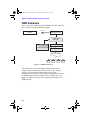
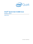
Screen Layout
The SMOR interface works like the Windows Explorer treestructured interface. The screen, shown in Figure 2-1, is divided
into three major components: a menu bar across the top of the
screen and two display panes below the menu bar.
Figure 2-1 Screen Layout
2-6
Combined RAID SW-UG.book Page 7 Monday, September 9, 2002 1:25 PM
Storage Manager on ROM
The Menu Bar
To open a specific menu, press Alt+highlighted letter of the menu
name. After a menu is open, you can select a specific menu item by
pressing the key for the letter highlighted on the menu item. For
example, to select the Read System Config item on the File menu,
press Alt+F to open the File menu, then press R to select Read
System Config.
Note: Depending on your configuration, not all menu items
may be available. Unavailable menu items are shown in a
low-contrast color.
The Left Pane – Tree View
The Tree View, displayed in the left pane, is the central control for
SMOR. This view displays a tree structure that represents the
organization of the storage subsystem, including controllers,
storage devices, and arrays detected by SMOR. By moving the
highlight with the up and down arrows, you can select items you
want to view or configure. As items are highlighted, the associated
information on the item is displayed in the Information View
(display pane on the right side).
If an item in the Tree View is preceded by a plus sign, press Enter
or the plus key to expand the tree, showing the devices associated
with that item. If an item is preceded by a minus sign, press Enter
or the minus key to collapse that portion of the tree, hiding the
devices associated with that item.
If the text for an item is larger than the width of the Tree View
pane, you can scroll the pane horizontally by using the left and
right arrow keys.
2-7
Combined RAID SW-UG.book Page 8 Monday, September 9, 2002 1:25 PM
Adaptec Storage Management Software User’s Guide
The Right Pane – Information View
To the right of the component tree is the Information View pane.
This area displays information related to the currently selected
item in the tree on the left side. The specific information displayed
in the Information View varies depending on the item selected.
When there are separate types of information available for the
selected item, the Information View is separated into tabbed pages.
Tab pages are information or configuration parameters that are
related to the selected item.
To select a specific tab page within the Information View, press
Alt+highlighted letter on the tab. For example, to change to a
controller’s Configuration tab, press Alt+C. You can also press the
Tab key when in the Tree View to move over to the currently
displayed Information View tab page. On a tab page within the
Information View, you can move between the items with the Tab
or Shift+Tab keys. See Keyboard Reference on page 2-3 for additional
details on changing between the Tree View and Information View,
using the menu bar, and navigating within the SMOR interface.
Within the Information View, select an item to configure by using
the Tab or Shift+Tab keys to move the highlight to the item. Items
that cannot be selected are shown in black. The way in which you
change an item depends on the type of control associated with the
item. Checkboxes are toggled by using the Spacebar. List-box
items (for example, Transfer Rate) are changed using the up and
down arrow keys. List box items can be recognized by the
downward pointing arrow at the right of the item.
To exit the Information View and return to the Tree View, press
Esc. If you have changed the configuration, save changes if desired
by using the Tab key to select Yes or No and then pressing Enter.
Note: The items and settings shown in the Information View
vary depending on the type of controller, device, or array
selected in the Tree View.
2-8
Combined RAID SW-UG.book Page 9 Monday, September 9, 2002 1:25 PM
Storage Manager on ROM
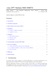
Running SMOR
Start SMOR by pressing Ctrl+A when the RAID controller BIOS
message appears on the screen during the boot sequence. SMOR
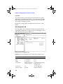
starts by displaying its opening screen, as shown in Figure 2-2.
Figure 2-2 SMOR Welcome Window
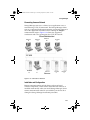
The letters that appear during the initial device scan process are
C
CD
D
Hard drive
E
SAF-TE, intelligent RAID enclosure, or processor
device
H
Hot spare drives
T
Tape device
0, 1, 5
Physical arrays identified by the RAID level
The position of a letter corresponds to the device ID assigned to
that device.
Note: The scans occur and display for only a few seconds.
2-9
Combined RAID SW-UG.book Page 10 Monday, September 9, 2002 1:25 PM
Adaptec Storage Management Software User’s Guide
Information and Configuration Views
When you highlight an item within the Tree View, the
corresponding Information View is displayed.
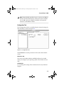
Controller BIOS Settings
The controller displays the default Information View when SMOR
starts, as shown in Figure 2-3.
Figure 2-3 Configuration Window
The settings in this view affect the controller BIOS and all the
Adaptec controllers in your system. To view or change these
settings, highlight Configuration in the Tree View.
The following table illustrates the default settings to be found in
the windows shown in Figure 2-3.
Controller Options
Default
Available Settings
Enable SCSI CD-ROM Boot
Disabled
Enabled
INT13 Cache Setting
Write Through
Write Back
Scan Delay (seconds)
Default
1, 10, 20, 30
EBDA Relocation
Disabled
Enabled
Enable Extended Int13
Enabled
Disabled
SmartROM Options
2-10
Combined RAID SW-UG.book Page 11 Monday, September 9, 2002 1:25 PM
Storage Manager on ROM
Enable SCSI CD-ROM Boot
When enabled, the BIOS attempts to detect a bootable CD-ROM
that uses the El-Torito format. This setting is disabled by default,
because some bootable CD-ROMs contain device-specific boot
code that is not supported by Adaptec controllers.
INT13 Cache Setting
This setting determines how the controller responds to Int13 write
commands under DOS and certain operating system installation
programs. The default is Write Through to avoid problems that can
occur during operating system installation if write-back caching is
enabled. After the operating system is installed, you can change to
Write Back caching for improved performance.
Change this setting back to Write Through during future operating
system installs or upgrades to avoid problems.
Scan Delay
Some devices require a time interval between power on, bus reset,
and scan or they do not respond correctly. If devices are not
displayed in the Tree View after power on, set the delay to a longer
interval.
EBDA Relocation
This setting determines the way that RAID controllers handle
Extended BIOS Data Area (EBDA) relocation. The default is
disabled. If the RAID controller does not behave as expected
enabling this option may resolve problems caused by conflicts with
other adapter cards.
Enable Extended Int13
This option enables extended Logical Block Addressing (LBA) for
hard drives. LBA enables operating system access to drives larger
than 8.6 GB. You should not change this setting.
2-11
Combined RAID SW-UG.book Page 12 Monday, September 9, 2002 1:25 PM
Adaptec Storage Management Software User’s Guide
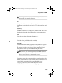
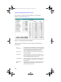
Information Tab
To view or change the configuration of the controller, highlight the
controller in the Tree View. Available tabs are Information and
Configuration, as shown in Figure 2-4.
Figure 2-4 Information Tab
The Information tab for a controller displays general information
reported by that controller. Fields may have special conditions:
Model
Controller model number
Serial #
Controller serial number
NVRAM Ver.
Version number for NVRAM settings
Cache
Amount of installed cache memory
Revision
Controller firmware revision
FW Type
Firmware type
ECC
Yes if Error Correction Code (ECC) memory is installed
SCSI Bus
Busses
Number of buses on the controller
SCSI ID
SCSI ID assigned to controller
Transfer
Maximum possible transfer rate
Host Bus
Type
PCI 64-bit
Transfer
Host PCI transfer rate: 528 MB/sec
2-12
Combined RAID SW-UG.book Page 13 Monday, September 9, 2002 1:25 PM
Storage Manager on ROM
Note: Adaptec RAID controllers report a cache size 16 MB less
than the total installed memory value because the controller
uses 16 MB as processor RAM. Controllers will report the
amount of cache RAM available.
Configuration Tab
The Configuration tab for a controller displays internal settings for
that controller, as shown in Figure 2-5.
Figure 2-5 Configuration Tab
Select Default to reset the parameters on this tab to their default
values.
Mem Address, IRQ
The values in the Mem Address and IRQ fields may be needed
when you configure your operating system. These fields are read
only.
PCI MWI Enable
Do not change this setting unless instructed to do so by Technical
Support.
2-13
Combined RAID SW-UG.book Page 14 Monday, September 9, 2002 1:25 PM
Adaptec Storage Management Software User’s Guide
Boot Enable
This option enables you to modify the boot process for systems
with multiple peripheral controllers in cases where the controller
BIOS does not provide effective or appropriate default operation.
This setting is enabled by default.
Disable this setting and the controller can not be used as a boot
device.
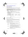
Bus Configuration Tab
This tab enables you to modify the hardware parameters for the
highlighted controller bus; it appears when you highlight a device
in the Tree View, as shown in Figure 2-6.
Figure 2-6 Bus Configuration Tab
Default resets the parameters on this tab to their default values.
Controller Parameter
ID
Type
Width
Transfer Rate
Default
7
As reported
As reported
Maximum allowed
for the controller
Termination
Bus boot enable
On
Enabled
2-14
Available Settings
SCSI: 0 – 6
N/A
N/A
Ultra320, Ultra160, Ultra2,
Ultra, FAST, 8, 5
Asynchronous
On, Off, High Only
Enabled, Disabled
Combined RAID SW-UG.book Page 15 Monday, September 9, 2002 1:25 PM
Storage Manager on ROM
Note: As reported means that the field displays the value
returned by the controller firmware.
Bus
Each peripheral bus on a controller is assigned a number.
Numbering starts with 0 for the first bus, 1 for the second bus, and
so on.
ID (SCSI only)
SCSI RAID controllers are configured by default at ID 7. This value
should not be changed unless required for special configurations.
Type
This is the type of bus (Ultra320, Ultra160, etc.).
Width
The width of the parallel bus (8-bit or 16-bit).
Transfer Rate
The controller automatically negotiates with each device at powerup or reset to set the maximum transfer rate. This parameter limits
the transfer rate to the value selected. This setting should not be
changed except when you are troubleshooting bus errors.
Note: On buses, if setting this parameter to 5 MHz eliminates
bus data errors, this is usually an indication that the bus is too
long or that the bus is not terminated correctly.
Termination
This option controls the termination for the controller and bus. The
default value (On) should not be changed unless both internal and
external cables are attached to the controller. Refer to the
Configuring Termination section in the Adaptec SCSI RAID
Installation Guide for information on setting this parameter.
2-15
Combined RAID SW-UG.book Page 16 Monday, September 9, 2002 1:25 PM
Adaptec Storage Management Software User’s Guide
Device Information Tab
Individual devices are listed in the Tree View under the controller
to which they are connected, as shown in Figures 2-7. Highlight a
device to view its information tab page.
Figure 2-7 Device Information Tab
The Device Information tab displays general information and
configuration. This view is divided into three parts: Description,
SCSI Capabilities and Status.
The Description section displays a general description of the
highlighted device, as follows:
2-16
Description
Manufacturer name and model number as reported by
the device, followed by the icon for the device.
Revision
Device firmware revision.
Address
Device address in the form HBA x, Channel x, ID x, LUN
x. Display contains as much information as necessary to
unambiguously define the address of the device.
Capacity
Device capacity in MB. For removable media, the
reported capacity is for the currently inserted media or no
media inserted if no media is inserted. Tape drives do not
report media.
Block Size
Block size reported by device.
Combined RAID SW-UG.book Page 17 Monday, September 9, 2002 1:25 PM
Storage Manager on ROM
Negotiated
Bus speed negotiated between the device and the
controller.
Transfer
Rate
Maximum transfer rate for negotiated bus speed and
transfer path (8-bit, 16-bit).
The status condition is one of the following for attached devices:
Dead
Device failed to respond to controller commands. If the
device becomes available, it only changes status after
the system configuration is read or the host is
restarted.
Failed
Drive failure occurred.
Impacted
Performance degradation in response to server I/O
requests.
Missing
Drive is physically missing or does not respond to
commands on the device bus.
Optimal
Device is fully functional.
Uninitialized
Drive is operational, but has been initialized as part of
an array.
Verify
Verify operation is being performed on the array. I/O
performance is reduced.
Warning
Imminent failure on a device with a S.M.A.R.T. failure
prediction.
The SCSI Capabilities section is a list of controller capabilities. A
check mark next to a feature indicates that the drive supports the
feature.
2-17
Combined RAID SW-UG.book Page 18 Monday, September 9, 2002 1:25 PM
Adaptec Storage Management Software User’s Guide
Array and Array Group Information
The Information tab for any array may be viewed by highlighting
that array, as shown in Figure 2-8.
Figure 2-8 Array Group Information Tab
RAID 0 arrays are comprised of any number of drives greater than
1. RAID 1 arrays are comprised of a pair of drives. RAID 5 arrays
contain three or more drives.
After you create the arrays, one or more arrays of the same RAID
level can be combined into a multilevel RAID (see Creating a
Multilevel RAID on page 2-23). Arrays are striped into multilevel
RAIDs by the controller firmware. All the drives in an array or
multilevel RAID must be attached to the same controller, and
appear to the host as a single Logical Storage Unit (LSU).
Note: Arrays do not start building until a Set System Config
action has been performed.
The Array Information tab displays general array information and
hardware configuration. It is divided into three parts: Description,
SCSI Capabilities, and Status.
2-18
Combined RAID SW-UG.book Page 19 Monday, September 9, 2002 1:25 PM
Storage Manager on ROM
The Description section displays a general description of the
highlighted array, as follows:
Description
RAID level used for the array.
Revision
Firmware revision of the RAID controller.
Address
RAID address in the form dDbBtTdD, as described in
Device Address Syntax on page 4-2. Display contains as
much information as necessary to unambiguously
define the address of the device. Controllers always are
assigned the lowest logical address of any device in the array.
Capacity
The usable capacity of the array in MB. The available
capacity depends upon the RAID level of that array.
Removable
As reported by the devices in the array.
Read Only
As reported by the devices in the array.
Block Size
The sector (block) size of the selected device in bytes.
For hard drives, the value should be 512. If the size is not
512, use SMOR to do a low-level format and create 512-byte
sectors. See Formatting a Drive on page 2-25 for more
information.
Stripe Size
Displays the stripe size used to create the RAID.
The Status section displays the current status of the array. A
progress indicator (a numeric percentage of completion) can also
appear if the array is building or rebuilding. The status definitions
are listed below:
Building
The array is being built.
Created
The array or device is defined, but not initialized.
Dead
A Write Back Cache command to the array failed. This
is an unrecoverable failure.
Degraded
A single drive in the array failed; array performance is
degraded.
Impacted
A verification is being performed on the array; I/O
performance is affected.
Optimal
The array is fully functional.
Pending
The array has been created and the build is queued on
the controller, but not yet started.
Rebuilding
Data is being rebuilt onto a drive in the array.
2-19
Combined RAID SW-UG.book Page 20 Monday, September 9, 2002 1:25 PM
Adaptec Storage Management Software User’s Guide
Setting the Configuration
There are two configuration options on the File menu:
■
Read System Config—Causes SMOR to rescan to detect any
changes in hardware configuration or status. Any changes that
have been made and not saved are lost. This operation is run
automatically when SMOR is started.
■
Set System Config—Causes SMOR to save changes that have
been made to the storage subsystem configuration in the
controller memory. If any array groups or multilevel RAIDs
have been created or modified, this operation causes the
controller to initiate a build operation on the new groups.
Array Operations
This section describes how to use SMOR to create arrays and
multilevel RAIDs, delete arrays, assign hot spare drives, and
rebuild an array.
Creating an Array
To create an array, follow these steps:
1 Select RAID > Create. The RAID Type window appears as
shown in Figure 2-9.
Figure 2-9 RAID Type Window
2-20
Combined RAID SW-UG.book Page 21 Monday, September 9, 2002 1:25 PM
Storage Manager on ROM
2 When the RAID Type window appears, select the RAID level
you want to use. The default stripe size is selected
automatically; however you can select a different stripe size
value by highlighting the field and using the up and down
arrow keys to change the stripe size.
Note: Although you can change the stripe size, Adaptec
recommends using the default value, which has been selected
for optimum performance based on the type of disk array you
chose to create.
a When you are ready to proceed, select Ok.
b The Eligible Devices tab appears, as shown in Figure 2-10.
The list of eligible devices can be either individual hard
drives or previously created array groups. Array groups
appear in the list when you select RAID 0 and eligible array
groups exist.
Figure 2-10 Eligible Devices Tab
2-21
Combined RAID SW-UG.book Page 22 Monday, September 9, 2002 1:25 PM
Adaptec Storage Management Software User’s Guide
3 Select the devices you want to include in the array:
a To add devices to the array, highlight the device and press
the Spacebar. A check mark appears next to the device to
indicate that it has been selected. You might need to scroll
the display down to view all eligible devices.
b To remove a previously selected device from the array,
highlight the device and press the Spacebar.
4 When you are finished selecting drives for the new array, select
Done.
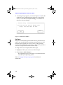
5 If you are creating a RAID 1 array, the RAID 1 Build Option
window appears, as shown in Figure 2-11. RAID 1 arrays are
built by copying the existing data from one device to the other.
Select the direction for the copy, then select Ok.
RAID 1 Build Option:
( ) Copy from (1,2,0,0) to (1,0,12,0)
(n) Copy from (1,0,12,0) to (1,2,0,0)
Ok
Cancel
Figure 2-11 RAID 1 Build Option Window
6 Select File > Set System Config to start the build process. The
build process begins for the array you created. If you created
multiple arrays, they are built serially in the order they were
defined. Alternatively, you can exit SMOR. Upon exiting, you
are prompted to save the configuration changes. If you save, the
build process begins for any arrays you defined.
For large redundant arrays, the build process can take several
hours to complete. You can exit SMOR and perform other activities
on the system while the build continues. An array being built can
be accessed during the build process.
If you exit SMOR and you want to monitor the progress of the
build operation, you can use the Storage Manager Array Group
Information window. See Array Groups on page 3-12 for additional
information.
2-22
Combined RAID SW-UG.book Page 23 Monday, September 9, 2002 1:25 PM
Storage Manager on ROM
Creating a Multilevel RAID
Creating a multilevel RAID (RAID 10 or 50) is similar to creating a
normal RAID 1 or RAID 5 array group. To create a RAID10 or
RAID 50 multilevel RAID, follow these steps:
1 Create and build your array groups as described in Creating an
Array on page 2-20. Do not initiate the build process on any
arrays that you intend to use in a multilevel RAID.
2 After you have created your initial array groups, select
RAID > Create again.
3 Select RAID 0 for the RAID type and click Ok.
4 Select two or more arrays of the same type from the list of
eligible devices, then click Done.
Note: You cannot combine arrays that use different RAID
levels.
5 Select File > Set System Config to begin the build process for
the multilevel RAID.
The Tree View displays the multilevel RAID LSU as
(x,x,x,x) FW RAID-0
with the array groups listed where drives would normally be
listed. Selecting an array group component branches to the hard
drives for that array group. The LSU address is the lowest address
of the array logical addresses that comprise the multilevel RAID.
Deleting an Array
To delete an array, follow these steps:
1 In the left pane, highlight the array that you want to remove.
Then, select RAID > Delete.
2-23
Combined RAID SW-UG.book Page 24 Monday, September 9, 2002 1:25 PM
Adaptec Storage Management Software User’s Guide
2 A warning message appears, as shown in Figure 2-12. Select Yes
or No. The array configuration for the devices is not deleted
until you select File > Set System Config or exit SMOR and
choose to save your changes.
Delete array
Are you sure you want to delete this
array? All data will be lost.
No
Yes
Figure 2-12 Delete Array Window
Hot Spares
Hot spares automatically replace failed drives in protected arrays
and are not accessible by the operating system for other use. Any
hard drive not assigned to an array or in use by the operating
system can be designated as a hot spare, as long as the spare drive
is at least as large as the other drives in the array.
To assign a drive as a hot spare, follow these steps:
1 Highlight the drive you want to use in the left pane.
2 Select Action > Make Hotspare.
The selected hot spare is reassigned as a normal hard drive
accessible by the operating system.
Refer to Assigning Hot Spares on page 3-42 for additional
information.
2-24
Combined RAID SW-UG.book Page 25 Monday, September 9, 2002 1:25 PM
Storage Manager on ROM
Rebuilding a Failed Array
To replace a failed drive in an array that is not protected by an
automatic hot spare, follow these steps:
1 Remove and replace the failed drive according the procedures
in your hardware documentation.
2 When the failed drive has been replaced, select
RAID > Rebuild Array to start the rebuild process.
The status of the array changes to Rebuilding (view the
Information tab for that array). When the rebuild is complete, the
array status changes to Optimal.
Note: Supported SAF-TE or SES enabled enclosures
automatically detect the replacement of a failed drive and the
controlelr will initiate a rebuild as soon as the new drive is
online.
Formatting a Drive
Formatting hard drives is not normally required. However, if you
have a drive that was previously formatted with a sector size other
than 512 bytes, low-level format the drive to 512 bytes/sector.
!
Caution: Do not remove power from the drive until the format
operation is completed. Doing so may damage the drive so
that it requires factory repair or replacement.
Low-level formatting large capacity drives can take considerable
time. To perform a low-level format on a hard drive, follow these
step:
1 Highlight the drive to be formatted
2 Select Action > Format Drive.
3 Select Ok and confirm. To determine if the format has
completed, view the Information tab for that drive.
2-25
Combined RAID SW-UG.book Page 26 Monday, September 9, 2002 1:25 PM
Adaptec Storage Management Software User’s Guide
Upgrading Firmware – Flash HBA Option
The firmware on your controller is upgradable using the Flash
HBA option, which appears on the Action menu when a controller
is selected in the Tree View. The Flash HBA option enables you to
upgrade to the latest firmware, controller BIOS and SMOR.
Note: There is no way to backup the controller firmware.
When you upgrade to the latest firmware, the previous
firmware image is replaced by the new one and any settings
you may have made are lost.
Each component must be upgraded as a separate operation,
however, they should all be upgraded at the same time. Adaptec
periodically releases updated firmware, controller BIOS, and
SMOR. You can obtain the latest files from the Adaptec website
(www.adaptec.com).
■
Firmware image upgrades are contained in a xxxxxxxx.ima or
xxxxxxxx.fwi file, where the 8-character file name consists of the
4-digit controller model number and a 4-digit release number.
■
Controller BIOS images are contained in a file named i2obios.xxx
(where, xxx is the version number).
■
SMOR updates are contained in a file named smoryyyy.xxx.
Where, yyyy is the build number and the file extension (xxx) is
the version number.
Copy these files to a floppy disk, CD or hard disk drive partition
formatted with a FAT16 filesystem.
To upgrade the controller firmware, BIOS, and/or the SMOR
utility, follow these steps:
1 Obtain the applicable firmware, BIOS, and/or SMOR utility
image files.
2 Insert the image files disk in a drive that is connected to the
system where the controller is installed.
3 In the Tree View, select the controller that you want to update.
2-26
Combined RAID SW-UG.book Page 27 Monday, September 9, 2002 1:25 PM
Storage Manager on ROM
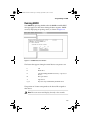
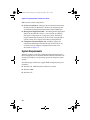
4 Select Action > Flash HBA. The Source File Browser window
appears, as shown in Figure 2-13.
-A:
2
I
S
-
20103A0H.ima
100320B.IMA
I20BIOS.160
2OBIOS.134
SMOR0031.112
MOR0031.112
#0 22100S:
100S:
#0
Select
for for
flashflash
Selecta asource
source
image
thethe
browser.
Imageusing
using
browser.
Select
button
to start
SelectOK
OK
button
to start
flash
flashprocedure.
procedure.
Ok
Ok
Cancel
Cancel
Figure 2-13 Source File Browser Window
5 In the Source File Browser window, select the drive that
contains the image files. Press Enter to expand the drive listing.
6 Highlight the image file you want to use and select Ok to
update the controller flash ROM. After the controller reads the
image, it displays the version number of the component you
selected. Select Yes to confirm. A progress indicator appears
showing of the flash operation.
If the operation does not complete successfully, refer to the
procedures for recovering from an incomplete or failed flash ROM
upgrade in the Troubleshooting section of the Adaptec SCSI RAID
Installation Guide.
2-27
Combined RAID SW-UG.book Page 28 Monday, September 9, 2002 1:25 PM
Adaptec Storage Management Software User’s Guide
Creating a SMOR Boot Disk
To create a SMOR boot disk, click Action > Make Boot Floppy or
use the Adaptec RAID Installation CD. You may need a SMOR boot
disk in certain situations when it is not possible to access SMOR by
typing Ctrl+A during startup. To create a SMOR boot disk
1 Insert a blank disk into the disk drive.
2 Select Action > Make Boot Floppy.
3 When prompted, select Yes to create the bootable disk. A
progress indicator appears showing the progress of the disk
creation. When finished, the progress meter closes.
To use the bootable disk with SMOR, follow these steps:
1 Insert the bootable disk you created into your disk drive.
2 Restart your system. The system boots from the disk and starts
SMOR automatically. If the system attempts to boot from
another device, you must change the boot order setting in your
system BIOS setup. Refer to your system documentation for
information about changing this setting.
3 Use this version of SMOR to perform whatever tasks are
necessary to configure your storage subsystem.
4 When you are finished, remove the disk from the disk drive.
Select File > Exit to exit SMOR.
Note: Exiting automatically restarts the computer. Leave the
bootable disk in the disk drive, it will restart SMOR.
2-28
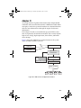
Combined RAID SW-UG.book Page 1 Monday, September 9, 2002 1:25 PM
3
Storage Manager
In this Chapter
Introduction
3-2
Installing Storage Manager
3-4
Running Storage Manager
3-5
Views
3-6
Status Reporting
3-22
Information Windows
3-22
Events
3-32
Formatting Drives
3-40
Drive Failures
3-41
Running a Verify Process
3-43
Controller I/O Statistics
3-45
Remote Communication
3-50
3-1
Combined RAID SW-UG.book Page 2 Monday, September 9, 2002 1:25 PM
Adaptec Storage Management Software User’s Guide
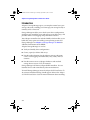
Introduction
Adaptec’s Storage Manager gives you complete control over your
storage subsystem, enabling you to manage your storage locally or
remotely across a network.
Storage Manager enables you to check your device configuration,
configure your controller, create and manage your disk arrays, and
provides online event logging and performance statistics.
Your Adaptec controller also includes SMOR, which enables you to
build disk arrays prior to installing your operating system and
Storage Manager. See Chapter 2, Storage Manager on ROM for
additional information about SMOR.
Adaptec Storage Manager is used to:
■
Verify and modify drive configurations
■
Create, expand, or delete disk arrays.
■
Provide online functions for the Adaptec storage subsystem
such as event logging and notification, array status, and I/O
statistics.
■
Provide remote access to Adaptec hardware and attached
storage devices across a TCP/IP network.
Storage Manager will detect Adaptec RAID controllers. It is not
intended for use with controllers by other manufacturers.
To install Storage Manager, insert the Adaptec RAID Installation CD.
An autorun installation dialog should appear. Refer to the Adaptec
SCSI RAID Installation Guide for more information about installing.
3-2
Combined RAID SW-UG.book Page 3 Monday, September 9, 2002 1:25 PM
Storage Manager
System Requirements
Adaptec Storage Manager software and device drivers require
approximately 4 MB of disk space. The host system should have at
least 64 MB of memory and a Pentium processor (200 MHz or
faster). A mouse and SVGA color monitor are required.
The host system should comply with the PCI Local Bus Specification
(revisions 2.1 and 2.2) and must be able to properly configure
multifunction PCI devices where one of the devices is a bridge.
If remote communication services are to be used to monitor and
control the array(s) using a network connection, then a network
connection is also required.
Storage Manager can be installed on a computer with one of the
following operating systems:
■
Windows XP, Windows 2000, Windows NT 4 (Service Pack 6 or
later).
■
Red Hat Linux 7.3
■
For details on the latest Linux releases supported go to
linux.adaptec.com.
Before running Storage Manager, be sure that your mouse driver is
installed. Access to some features of Storage Manager requires the
use of a pointing device in place of the keyboard.
3-3
Combined RAID SW-UG.book Page 4 Monday, September 9, 2002 1:25 PM
Adaptec Storage Management Software User’s Guide
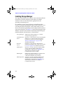
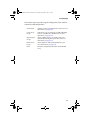
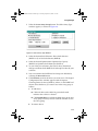
Installing Storage Manager
The original installation of the software starts with the installation
instructions covered in chapter 4 of the Adaptec SCSI RAID
Installation Guide. Use the instructions appropriate for the
operating system being used.
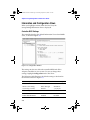
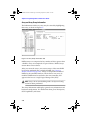
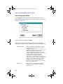
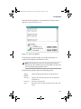
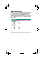
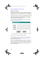
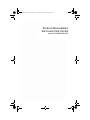
On a Windows system, after the drivers are installed and the
system is restarted, reinserting the Adaptec RAID Installation CD or
executing autorun.exe will display a menu from which you can
choose to install Storage Manager, install Adobe Acrobat reader or
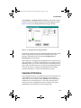
create driver diskettes. See Figure 3-1 on the following page for the
Windows selection screen from the installation utility. During the
initial installation, select the boxes as shown below:
Storage Manager
Required for initial installation -- Loads the
Storage Manager application.
Communications
Server
Optional -- Loads software to allow controlling the
RAID array(s) on this machine from another
machine via a network connection. Refer to
Remote Communication on page 3-50 for
detailed information.
3-4
Broadcast
Service
Optional -- Loads software components for
tracking and logging events on the array(s). Refer
to Events on page 3-32 for further information.
SNMP Agent
Optional -- Used in conjunction with the SNMP
service, which should be installed prior to
installing this component. See Appendix A for
details. May be used instead of the
Communications Server or DMI.
RAID Engine
Required for initial installation -- Loads the DLL
used by other applications that need to
communicate with the array hardware.
DMI Component
Optional -- Used in conjunction with the DMI
standard, which should be installed prior to
installing this component. See Appendix B for
details. May be used instead of SNMP or
Communications Server.
Combined RAID SW-UG.book Page 5 Monday, September 9, 2002 1:25 PM
Storage Manager
.
Figure 3-1 Storage Manager Setup Window
Running Storage Manager
You can run Storage Manager in one of the following ways:
■
Locally—On the same computer that contains the RAID
controller and drives.
■
Remotely—Across a TCP/IP network, you can view and
configure servers from remote locations.
Using Storage Manager Locally
Storage Manager scans for RAID controllers installed on the
computer on which it is run. If one or more controllers are found,
the storage subsystem hardware configuration is displayed.
Using Storage Manager Remotely
Host systems can be viewed and configured across a TCP/IP
network from a client system running Storage Manager.
3-5
Combined RAID SW-UG.book Page 6 Monday, September 9, 2002 1:25 PM
Adaptec Storage Management Software User’s Guide
Views
This section describes the two primary configuration views, which
are:
■
Physical Configuration View
■
Logical Configuration View (includes Logical Device
Addresses)
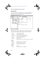
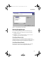
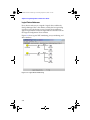
Physical Configuration View
The first window displayed by Storage Manager is the Physical
Configuration View (see Figure 3-2). This window displays each
RAID controller in the system along with the peripheral buses and
attached devices. Icons representing hard drives, CD-ROMs, tapes,
bridge controllers, and jukeboxes are displayed. Devices are sorted
by controller number and device ID from lowest to highest.
RAID hard drive icons contain the word “RAID”. Hot spare icons
have a red circle with a white cross. Select Legend of Icons from
the Storage Manager Help menu to see a list of the various icons
and their meaning.
3-6
Switch View
Toggles between the Physical Configuration View
and the Logical Configuration View window.
Create Array
Group
Starts the process of creating a RAID logical disk.
Print
Prints a text report of the subsystem configuration.
Combined RAID SW-UG.book Page 7 Monday, September 9, 2002 1:25 PM
Storage Manager
Figures 3-2 shows a sample view of a Physical Configuration.
Figure 3-2 Physical Configuration Window
3-7
Combined RAID SW-UG.book Page 8 Monday, September 9, 2002 1:25 PM
Adaptec Storage Management Software User’s Guide
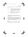
Logical Configuration View
On the right side of the Logical Configuration View Window,
shown in Figure 3-3, are all the physical devices that are attached to
the RAID controllers.
Figure 3-3 Logical Configuration Window
On the left side of the window are the associated logical devices as
seen by the host computer.
Storage Manager displays the same icon for non-hard-drive
devices in both logical and physical views. Hard drives appear
either as individual drives or as members of arrays. In either case,
the drive or array is represented on the left side of the window as a
Logical Storage Unit (LSU). Arrays that make up a multilevel RAID
are displayed as RAID 1 or RAID 5 icons that appear between the
LSU icon on the left and the drives on the right.
Devices are displayed in order of device type, with all non-harddrive devices displayed first, followed by all hard drives not
assigned to an array, then hot spares, and finally all arrays by RAID
level.
3-8
Combined RAID SW-UG.book Page 9 Monday, September 9, 2002 1:25 PM
Storage Manager
The tool bar at the top of the Logical Configuration View window
contains the following buttons:
Switch View
Switches to the Logical Information View. For more
information, see page 3-20.
Create Array
Group
Starts the process of collecting available individual
drives to assemble into a RAID array. For more
information, see page 3-14.
Expand Array
Group
Allows adding drives to an existing array and
dynamically resizing the logical drive. For more
information, see page 3-19.
Delete Array
Group
Allows deletion of the selected RAID array. For
more information, see page 3-21.
Print
Prints the configuration file of the selected RAID
array.
3-9
Combined RAID SW-UG.book Page 10 Monday, September 9, 2002 1:25 PM
Adaptec Storage Management Software User’s Guide
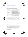
Logical Device Addresses
Every device and array is assigned a logical device address by
Storage Manager. This is the address used by the host operating
system to access the device or array. Logical device addresses
appear in parentheses under the logical device and LSU icons on
the Logical Configuration View window.
Figure 3-4 shows typical LSU numbering, array numbering, and
drive numbers.
Figure 3-4 Logical Device Addressing
3-10
Combined RAID SW-UG.book Page 11 Monday, September 9, 2002 1:25 PM
Storage Manager
The complete logical device address is composed of the following
fields:
HBA
The controller to which the device is attached. PCI bus slots
are scanned from lowest to highest looking for Adaptec
controllers. As Adaptec controllers are found, they are
assigned numbers incrementally, starting with 0.
Bus
Channel number of the channel to which the device is
attached.
Device
The unique ID for that device. For an array this is the
lowest ID among the drives that make up the array.
LUN
The LUN for that device is normally 0.
Array groups are automatically assigned an address that
corresponds to the lowest logical device address used by a device
in that array group.
When an array group has been created, its logical device address
does not change if the drive with the lowest ID is replaced by a hot
spare. When a hot spare replacement occurs, the failed drive
automatically becomes the new hot spare. If you choose not to use
that drive as a hot spare, Storage Manager prompts you to select an
unused logical device address for that drive.
Example
If the lowest member device address for an array is HBA:0 Bus:1
ID:12 LUN:0, the LSU address is HBA:0 Bus:1 ID:12 LUN:0.
3-11
Combined RAID SW-UG.book Page 12 Monday, September 9, 2002 1:25 PM
Adaptec Storage Management Software User’s Guide
Array Groups
The tool bar at the top of the Logical Configuration View window,
shown in Figure 3-4, contains the following buttons:
Switch View
Switches to the Logical Information View. For
more information, see page 3-20.
Create Array Group
Starts the process of collecting available
individual drives to assemble into a RAID array.
For more information, see page 3-14.
Expand Array
Group
Windows XP, Windows 2000 and Windows NT
only—Allows adding drives to an existing array
and dynamically resizing the logical drive. For
more information, see page 3-19.
Delete Array Group
Allows deletion of the selected RAID array. For
more information, see page 3-21.
Print
Prints the configuration file of the selected
RAID array.
You can use the Logical Configuration View window to create any
combination of RAID level 0, 1, or 5 disk arrays. RAID 0 arrays can
be any combination of individual drives. RAID 1 arrays are
comprised of multiple pairs of drives. RAID 5 arrays contain three
or more drives.
One or more arrays of the same RAID level can be combined into a
multilevel RAID, such as:
■
RAID 10 for multiple RAID 1 arrays
■
RAID 50 for multiple RAID 5 arrays
The drives in a multilevel RAID appear as a single LSU to the host
computer.
Although arrays must be built from drives that are all attached to
the same controller, arrays can contain drives from multiple
channels. Arrays are built using the drives in the order selected,
regardless of which channel they are connected to.
Arrays created using drives on multiple channels can offer
performance benefits over single-channel arrays. Multiple channels
can also be used to create fault-tolerant arrays using pairs of drives
on alternate channels.
3-12
Combined RAID SW-UG.book Page 13 Monday, September 9, 2002 1:25 PM
Storage Manager
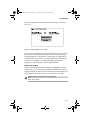
To view the Array Group Information window, shown in Figure
3-5, double-click the appropriate array icon in the Logical
Configuration View window.
Figure 3-5 Array Group Information Window
The Array Group Information window displays the following
information:
Name
The descriptive name assigned to the array. An icon
in the upper right corner of the window indicates
the RAID level.
Address
This is the logical device address used by the host
operating system to access the logical drive. The
address is the same as the lowest device address in
the array.
Capacity
The total usable storage capacity of the array in MB.
Status
The current status of the array as reported by the
controller.
Hotspares
Displays a list of any hot spare drives that are
available to protect the array in the event of a drive
failure.
Components
Displays the logical address, model, and stripe size
for each member of the array. If this is a multilevel
RAID Information window, the list displays the
address or name and stripe size for each disk array
that is a member of the multilevel RAID.
3-13
Combined RAID SW-UG.book Page 14 Monday, September 9, 2002 1:25 PM
Adaptec Storage Management Software User’s Guide
Note: The availability of the various buttons depends on the
current configuration and state of the array.
The toolbar at the bottom of the Array Group Information window
contains the following buttons:
Event Log
Displays the activity log of the RAID system. For
more information, see page 3-32.
I/O Stats
Displays the log of the array’s I/O activity. For more
information, see page 3-45.
Verify
Starts the process of checking the current status and
operability of the RAID array. For more information,
see page 3-43.
Expand
Windows XP, Windows 2000 and Windows NT only—
Allows setting and checking the parameters of the
RAID controller. For more information, see page
3-19.
Name
Allows entering or changing the name to be shown
for this RAID array. This does not affect the LSU of
the array. For more information, see page 3-21.
Configure
Allows changing the configuration of the array.
Print
Prints the configuration file of the selected RAID
array.
Build
Arrays that have a build pending display this
button.
Rebuild
Redundant arrays that have a failed drive show this
button.
Stop Bld
Arrays that are building or rebuilding show a Stop
Bld button.
Stop Vfy
Arrays running a Verify operation show this button.
Creating an Array Group
To create an array group, follow these steps:
3-14
Combined RAID SW-UG.book Page 15 Monday, September 9, 2002 1:25 PM
Storage Manager
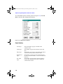
1 Select the Create Array Group button. The Select Array Type
window appears, as shown in Figure 3-6.
Figure 3-6 Select Array Type Window
2 Select the desired Fault Tolerance: Drive fault tolerance
(RAID 1 or 5) or No fault tolerance (RAID 0).
3 Select the desired Optimization: Optimize for Capacity
(RAID 5) or Optimize for Performance (RAID 1).
4 As you make your selections, the Chosen Array Parameters
change to indicate which RAID level and stripe size best fit your
selection.
5 You can customize the RAID level and stripe size defaults by
selecting the Override button.
6 Click Continue to select the drives you want to use. The Logical
Configuration View window appears with the caption
Choosing Drives for Array (RAID n), where n is the RAID level
chosen. Select the drives you want to use in the array group as
follows:
a To add drives
■
Click each drive to be added. A green check mark
indicates that a drive is selected.
■
Click Include Drive to add the marked drives to the new
array group. You may need to scroll the window to view
the array group.
b To remove drives
3-15
Combined RAID SW-UG.book Page 16 Monday, September 9, 2002 1:25 PM
Adaptec Storage Management Software User’s Guide
■
Click the drive icons you want to remove and then click
Remove Drive.
During the drive selection process some drives might be
displayed in a blue color. This indicates that these drives cannot
be included in the array unless you change the configuration.
You must either select more drives for the array or remove one
or more drives from the array. See Array Groups on page 3-12
for rules regarding the number of drives that can be included in
arrays.
7 When you finish selecting the drives to be included in the new
array group, click Done. The icon for the array group appears
with a black flag until you start the build process by saving
your changes.
8 When you are finished creating arrays, exit Storage Manager.
You are prompted to save the configuration changes. If you save
the configuration, the build operation starts automatically. If
you have created multiple arrays, they are built one at a time in
the order created. You can also start the build without exiting
Storage Manager by selecting File–Set System Configuration.
Note: Depending on the size of the array, the initialization
process can take several hours to complete. You can exit
Storage Manager and perform other activities on the system
while the build continues. Arrays can be accessed while the
initialization occurs as a background task.
Furthermore, redundant arrays provide redundancy
immediately although the performance of the array will be
less than optimal until the initialization is complete.
RAID 1 arrays are created by copying the data on one drive of the
mirrored pair to the other. If you have specified a RAID 1 array,
3-16
Combined RAID SW-UG.book Page 17 Monday, September 9, 2002 1:25 PM
Storage Manager
you are prompted to select the direction of the copy as shown in
Figure 3-7.
Figure 3-7 Mirroring Drives in an Array
If you want to monitor the progress of the build operation, display
the Array Group Information window for the new array group.
The build progress is displayed as a percentage of completion in
the Status field. You can also view the Information window for an
array that is a member of a multilevel RAID to monitor the
progress for that component of the multilevel RAID.
Naming an Array Group
In the Array Group Information window, click Name to assign a
unique name to an array group or multilevel RAID. This name is
displayed under the Array icon and other locations that display the
array identifier. The name can be 1 to 13 characters in length.
Note: You must restart the host computer before the new array
name takes effect.
3-17
Combined RAID SW-UG.book Page 18 Monday, September 9, 2002 1:25 PM
Adaptec Storage Management Software User’s Guide
Expanding and Extending Arrays – Windows XP, Windows 2000 and
Windows NT only
The following definitions are used in this section:
■
Array expansion—Adding additional space to an existing array
group using the array expansion feature.
■
Volume extension—Adding the new space created by the array
expansion to the existing Windows volume (LSU).
Array expansion enables you to increase your storage capacity by
adding one or more drives to your RAID 0 and RAID 5 arrays
while your system remains online. As additional drives are added,
the controller redistributes the data on the array, placing new space
at the end of the LSU and increasing the size of the logical drive.
Before array expansion was available, to increase the size of an
array you had to backup the data on the array, shutdown the host
system, delete the old array, and then build a larger array that
included the new drives. After the larger array was built, you
would reinstall the operating system (if necessary) and restore the
data from the backup. This entire process could keep your system
off-line for at least one day and possibly longer.
The array expansion feature enables you to add the new drives to
the array while the system is active and users are logged in and
accessing data. After the array is expanded, use the Windows Disk
Administrator to add the additional space to the volume set of the
array, then shutdown the system and restart. When the system
restarts, Windows recognizes the additional space as part of the
existing logical drive.
Note: Overall system performance is reduced significantly
during the array expansion process. To mitigate the impact,
adjust the relative priorities of processes in Storage Manager
by setting the Background Task Priority (see page 3-44).
Array expansion maintains the performance gains of RAID 0 and
RAID 5, spreading accesses randomly across the drives in the array.
The controller presents the same number of LSUs to the operating
system after the expansion. There is no need for manual load
balancing, which would be required if the new space were
presented as an additional LSU.
3-18
Combined RAID SW-UG.book Page 19 Monday, September 9, 2002 1:25 PM
Storage Manager
Requirements and Restrictions
Array expansion has the following system requirements and
restrictions.
■
Windows XP, Windows 2000, Windows NT 4.0, Server or
Workstation, with the most recent service pack.
■
Adaptec supplied driver only. (The Microsoft OSM does not
support array expansion.)
■
RAID 0 or RAID 5 array groups only
■
NTFS file system only. (You cannot extend a volume that has a
FAT partition. Instead, you would add the extra space as a
separate LSU.)
■
You cannot extend the Windows XP, Windows 2000 or
Windows NT boot partition.
■
The array must have Optimal status before beginning the
expansion. If the array status is not Optimal, correct the problem
and complete a rebuild of the existing array before continuing
with expansion.
■
Each new drive added to an array must be at least equal to the
capacity of the smallest capacity drive already in the array. This
is because in any RAID configuration, the drive with the least
capacity in the array determines the usable capacity of all the
drives in the array. There is no advantage in adding a drive with
a capacity larger than the smallest capacity drive already in the
array.
Expanding an Array Group
To expand an existing array group, follow these steps:
!
Caution: Backup your data before changing the configuration
of a disk array. Do not allow power to the host system to be
interrupted while the expansion operation is running.
1 Connect the additional drives to the peripheral bus and poweron the drives. Refer to the Adaptec SCSI RAID Installation Guide
if necessary.
3-19
Combined RAID SW-UG.book Page 20 Monday, September 9, 2002 1:25 PM
Adaptec Storage Management Software User’s Guide
Note: If the drives are not in hot-pluggable carriers, power
down the system before adding drives to the peripheral bus.
2 Start Storage Manager and click Switch View to change to the
Logical Configuration View.
3 Select the array group to which you want to add drives by
clicking on the corresponding RAID 0 or RAID 5 icon.
4 Select Expand Array Group.
5 Mark the drives to be added to the array by clicking on them. A
green check mark indicates that a drive is selected.
6 Select Include Drive. This causes the marked drives to join the
existing array group. The drives to be added are now marked
New.
7 When you are finished choosing drives, select Done. The icon
for the array group appears with a black flag until the
expansion process is started.
8 Select File–Set System Configuration to start the array
expansion. The status flag on the array group turns blue and the
flags on the components turn white during the expansion
process. You can perform other activity on the system while the
expansion continues, because the array is fully functional
during the expansion process.
For large arrays, the expansion can take several hours to
complete. Host I/O activity can prolong the expansion process.
If you want to monitor the progress of the expansion operation,
you can use Storage Manager to view the Array Group
Information window. Status is Expanding during the expansion
process, Optimal when it has completed.
3-20
Combined RAID SW-UG.book Page 21 Monday, September 9, 2002 1:25 PM
Storage Manager
Note: If a drive fails during expansion, the expansion may
complete successfully. However, the new, larger array
remains in a degraded state until the problem is fixed. If there
is a hot spare associated with the array, the degraded array is
rebuilt using the hot spare. If there is no hot spare, replace the
defective drive and rebuild the array.
Reconfiguring and Array After Expansion
When the array expansion is complete, you need to configure the
array so that Windows recognizes the additional space. Follow
these steps:
1 Shut down and restart the system.
Note: When restarting, Windows runs chkdsk to verify the new
space.
2 Start Disk Administrator. The new space appears as free space
at the end of the existing logical drive.
3 Select both the original logical drive and the free space by
highlighting both segments.
4 Select Partition–Extend Volume Set... Select Yes when
prompted to save your changes and restart Windows.
Use the rdisk.exe utility to update your emergency repair disk with
the new disk configuration information.
Deleting an Array Group
To delete an array group, follow these steps:
1 From the Logical Configuration View window, select the LSU or
array group icon of the array you want to delete. Then, select
Delete Array Group.
2 Select OK when the confirmation message appears to complete
the delete operation. Click Cancel to exit without deleting the
array group.
3-21
Combined RAID SW-UG.book Page 22 Monday, September 9, 2002 1:25 PM
Adaptec Storage Management Software User’s Guide
An array is not physically deleted until you exit Storage Manager
and choose to save changes or select File > Set System
Configuration.
Status Reporting
Status is reported by RAID controllers for arrays and drives. Some
status conditions are indicated by Storage Manager through status
flags on the drive or array icons. More detailed status information
can be obtained by viewing the Information window for that drive
or array. Changes in status conditions are logged and can also be
broadcast to selected recipients.
The general status conditions that can be indicated for drives or
arrays are listed below. The actual status message may include
additional details:
Building
The array is being built.
Created
The array or device is defined, but not initialized.
Dead
A write-back cache to the array command failed. This
is an unrecoverable failure.
Degraded
A single drive in the array has failed; array
performance is affected.
Impacted
A verification is being performed on the array; I/O
performance is affected.
Optimal
The array is fully functional.
Pending
The array has been created and the build is queued on
the controller, but is not yet started.
Rebuilding
Data is being rebuilt onto a drive in the array.
Information Windows
This section discusses information windows, which includes:
■
Host Bus Adapter Information Window on page 3-23
■
Configure Host Bus Adapter Window on page 3-24
■
Flash Configuration Window on page 3-26
■
Device Information Window on page 3-28
■
Device Configuration Window on page 3-30
3-22
Combined RAID SW-UG.book Page 23 Monday, September 9, 2002 1:25 PM
Storage Manager
Double-click a controller or device icon to display an Information
window for that controller or device.
Host Bus Adapter Information Window
This window (see Figure 3-8) displays HBA configuration
information reported by the selected controller.
The Controller section displays the Model, Serial #, Firmware
revision, and amount of installed cache. ECC is checked only if
ECC memory is installed.
The Attached Modules section shows the expansion modules and
type and capacity of memory modules installed.
The Host Bus Adapter Info window displays the current bus
configuration.
Figure 3-8 Host Bus Adapter Info Window
Note: The RAID controller requires 16 MB of memory for its
operation. The available cache memory reported here equals
the amount of memory installed minus 16 MB.
3-23
Combined RAID SW-UG.book Page 24 Monday, September 9, 2002 1:25 PM
Adaptec Storage Management Software User’s Guide
The following buttons are available:
Configure
Examine and change HBA parameters, or download
new firmware code. For more information, see page
3-24.
Event Log
Examine records of transfers to and from attached
devices. For more information, see page 3-32.
I/O Stats
Examine records of cache and command transfers. For
more information, see page 3-45.
Print
Print this window.
OK
Accept changes and return to previous window.
Configure Host Bus Adapter Window
Click Configure in the Host Bus Adapter Info window to modify
hardware parameters for the RAID controller, The Configure Host
Bus Adapter window appears, as shown in Figure 3-9.
Figure 3-9 Configure Host Bus Adapter Window
3-24
Combined RAID SW-UG.book Page 25 Monday, September 9, 2002 1:25 PM
Storage Manager
The following buttons are available:
Flash
Displays the Flash Configuration window to update
the controller firmware and BIOS.
Caching
Selects the controller cache parameters.
Defaults
Resets the controller configuration to factory default
settings.
Cancel
Cancels any changes you have made and returns to
the Host Bus Adapter Info window.
SCSI ID
Your controllers is set to ID 7 by default. Refer to the
Adaptec SCSI RAID Installation Guide for more
information about selecting an alternate SCSI ID.
SCSI
TERMPWR
By default, SCSI RAID controllers supply
termination power through the TERMPWR line on
the SCSI cable. This setting does not normally need
to be changed.
Transfer
The maximum possible transfer rate. The controller
automatically negotiates with each device at powerup, or reset, to determine the maximum transfer
rate. This parameter should only be changed when
troubleshooting SCSI bus errors. If data errors are
eliminated by setting the value to a lower rate, there
might be problems with the length of the bus or the bus
termination.
Termination
This parameter sets SCSI termination for the
controller. The default value (On) should not be
changed unless both internal and external cables are
attached to the controller. Refer to the Adaptec SCSI
RAID Installation Guide for information about
configuring SCSI bus termination.
Address, IRQ
These fields display the controller memory address
and IRQ value assigned by the host BIOS. These
values cannot be changed.
Controller Caching – Windows NT only
To ensure optimum performance, follow these steps:
1 Click Caching in the Configure Host Bus Adapter window to
display the HBA Caching Configuration window.
2 When the HBA Caching Configuration window appears,
change both of the settings to Advisory.
3-25
Combined RAID SW-UG.book Page 26 Monday, September 9, 2002 1:25 PM
Adaptec Storage Management Software User’s Guide
The Advisory setting allows the controller to use its own
algorithms for cache management. This is more efficient than
allowing the operating system to direct the cache operation.
3 Click OK to exit the window and save the changes.
4 Reboot Windows to enable the new settings.
Note: If you reset the NVRAM on the controller, the changes to
your cache settings may not be retained. In that case, repeat
this procedure to ensure optimum performance.
Flash Configuration Window
When you click Flash in the Configure Host Bus Adapter window,
the Flash Configuration window, shown in Figure 3-10, is
displayed.
Note: It is easier to perform an update if the image files are
placed in the root directory of a disk. Each component must
be upgraded as a separate operation. Flash operations are not
supported over remote connections.
Figure 3-10 Flash Configuration Window
3-26
Combined RAID SW-UG.book Page 27 Monday, September 9, 2002 1:25 PM
Storage Manager
The current controller model, firmware version, and firmware type
are displayed. To specify an image file for the flash operation, you
can type a path and filename in the Filename field or click Browse
to use a file selection window.
Firmware images are contained in a xxxxxxxx.ima file, where the
8-character file name consists of the 4-digit model number and a
4-digit release number. The controller BIOS image is contained in a
file named i2obios.xxx (where, xxx is the version number). SMOR
updates are contained in a file named smoryyyy.xxx. Where, yyyy is
the version number and the file extension (xxx) is the build number.
You can obtain the latest files by contacting your technical support
representative.
When you select an image file, Storage Manager reads the file to
determine the type of image selected: firmware, controller BIOS, or
SMOR. The Version, Date, and Type fields are displayed in the
corresponding section of the window.
Click OK to begin the flash operation. Click Cancel to return to the
Configure Host Bus Adapter window.
3-27
Combined RAID SW-UG.book Page 28 Monday, September 9, 2002 1:25 PM
Adaptec Storage Management Software User’s Guide
Device Information Window
The Device Information Window is shown in Figure 3-11.
Figure 3-11 SCSI Device Information Window
3-28
Combined RAID SW-UG.book Page 29 Monday, September 9, 2002 1:25 PM
Storage Manager
The Device Information window displays the following
information:
Description
The manufacturer and model.
Revision
The drive firmware revision.
Address
The logical address of the device.
Capacity
Storage capacity of the device in MB. For
removable-media devices, capacity is reported for
the currently inserted media.
Sectors
Total number of sectors on the drive. SCSI devices
may refer to sectors as blocks in some other
reference material.
Bytes/sector
Sector size (always 512). A SCSI hard drive may
report otherwise; if so, low-level format the drive as
described in Formatting Drives.
Removable
Indicates that the drive uses removable media.
Transfer
Transfer rate.
Status
Current status of the array as reported by the
controller. General status conditions (other than
Optimal) are indicated by flags on the device icon.
The SCSI Capabilities section shows which
supported features are enabled [x] for the device.
For a list of valid statuses, refer to Status Reporting
on page 3-22.
RAID drives display the name and level of the array to which they
belong and the stripe size for the array.
Various buttons are available depending on device type. Hard
drives have Event Log and I/O Stats buttons. Hard drives that are
not members of a RAID have Make Hotspare, Configure, and
Format buttons. Print is always available.
Hard drives that are members of arrays display a Fail Drive button.
If the drive is a hot spare, the Remove Hotspare button replaces the
Make Hotspare button.
3-29
Combined RAID SW-UG.book Page 30 Monday, September 9, 2002 1:25 PM
Adaptec Storage Management Software User’s Guide
Device Configuration Window
Click Configure in either Device Information or Array Group
Information window to display the Device Configuration window,
shown in Figure 3-12.
Figure 3-12 Device Configuration Window
The Device Configuration window enables you to change the
caching parameters for your controller and provides the following:
3-30
Predictive Cache
Enables and disables the predictive caching
feature on RAID controllers. This feature is
disabled by default.
Predictive caching reduces average disk access
time by determining when the host is
requesting data that it read previously and
reading in additional sequential data before it is
actually requested, thereby enhancing
performance if your data management
application is single-threaded or generates only
a small number of concurrent outstanding I/O
requests. If your application does not fit this
description, there may be no benefit from
predictive caching and using it may adversely
affect overall performance.
Write-back
Defers writes to disk until after command
completion and generally provides better
performance.
Combined RAID SW-UG.book Page 31 Monday, September 9, 2002 1:25 PM
Storage Manager
Write-through
Writes all data to disk for each Write command
before Command Complete status is returned
to the host. The data can also be cached for
subsequent read commands.
Defaults
Click to revert to the default setting.
Cancel
Click to exit this window without saving
changes.
OK
Click to exit with changes.
Saving the Subsystem Configuration
The Storage Manager File menu has the following options:
Read System
Configuration
Reads the current hardware configuration. Any
current changes not saved are lost.
Set System
Configuration
Saves changes that you made to the storage
subsystem configuration. If any arrays have
been created or modified, this action causes the
controller to start build operations for the new
arrays.
Load Configuration
File
Loads a previously saved configuration into
Storage Manager and apply it to the current
hardware.
Save Configuration
File
Saves the current configuration, or any changes
to that configuration, to a file for later use.
Allows storage subsystems to be configured for
other machines with like drives.
Note: If you reset the NVRAM on the controller, any changes
to your controller parameters return to the factory defaults.
3-31
Combined RAID SW-UG.book Page 32 Monday, September 9, 2002 1:25 PM
Adaptec Storage Management Software User’s Guide
Events
Events are generated for detected fault conditions as well as RAID
status changes, and are described as follows:
Soft Error
An operation on a hard drive that caused an error,
but was successful after a retry.
Recoverable
Hard Error
An error on a hard drive, controller, or peripheral
bus, where the data was recovered using ECC or
from redundant array information.
Nonrecoverabl
e Hard Error
An error on a hard drive, controller, or peripheral
bus where the data could not be recovered using
ECC or from redundant array information.
Status Change
The status of an array or drive changed. Examples of
this would be a drive or array failure, or an array
build or rebuild operation that was initiated or
completed.
Event Log
When events occur, they are automatically logged in the cache on
the RAID controller where they occurred. In addition, you can
specify that Storage Manager maintain an event log on disk (see
Event Broadcaster on page 3-34). To display the contents of the event
log, click Event Log in any controller, drive, or array information
window. Only the events reported for the selected device or array
are displayed.
3-32
Combined RAID SW-UG.book Page 33 Monday, September 9, 2002 1:25 PM
Storage Manager
When the Event Log button is selected, the Event Logs window
appears, as shown in Figure 3-13.
Figure 3-13 Event Logs Window
The Event Logs window enables you to limit the display to a
specific level or higher (the default is level 4).
Note: Some important events may not be displayed by the
default level. You should select one of the higher event levels
to ensure displaying significant errors.
The Event Logs window allows the following actions:
Arrow
buttons
Adjusts the Display Threshold to the desired level.
View Log
Displays the event messages whose levels match the
selected levels.
Clear Log
Erases all event messages.
Print
Prints the event messages currently shown in the event
log list.
3-33
Combined RAID SW-UG.book Page 34 Monday, September 9, 2002 1:25 PM
Adaptec Storage Management Software User’s Guide
Note: Only the event messages that appear on the screen when
you click Print are printed. Therefore, if you want to print
specific messages, scroll the list until the messages are visible
and then click Print.
Event Broadcaster
If your operating system supports a broadcaster, Storage Manager
enables you to specify that event messages be sent to users, groups,
and devices, through email, to the system error log, and the
Adaptec log file. Select Options > Event Broadcast Control to
display the Event Broadcasting window, shown in Figure 3-14. The
options in the Event Broadcasting window may vary depending
upon your operating system.
Figure 3-14 Event Broadcasting Window
3-34
Stop
Broadcasting
Stops Storage Manager from sending event
messages to the addresses specified.
Unload
Broadcaster
Removes the broadcaster from the current set of
active services.
Combined RAID SW-UG.book Page 35 Monday, September 9, 2002 1:25 PM
Storage Manager
You can select or modify the following parameters:
Time Interval
Interval at which the broadcaster reads the
controller event logs.
Broadcast to
Computer(s)
When enabled, event messages are sent to each
system in the Computer Names list.
Local Desktop
Message
When enabled, event messages are displayed on the
local system desktop.
Email to users
When enabled, event messages are e-mailed to each
address in the Email Users list.
Log to Event
Viewer
When enabled, event messages are logged and
displayed in the Windows Event Viewer.
Event Logs
When enabled, event messages are logged to a
permanent log file.
Computer
Names/Email
Users
Use these fields to specify a list of computer
systems or email addresses that are to receive
broadcast messages.
Display
Threshold
Click the arrow buttons to adjust the indicator to
the threshold you want to use for reporting events.
Messages are broadcast for all events whose levels
match those selected.
Broadcasters are available on the following operating systems:
■
Windows XP, Windows 2000 and Windows NT
■
Red Hat 7.3
The broadcaster collects events logged by the controller in the host
system on which that broadcaster is running. The broadcaster
records these events to files for each controller for use by Storage
Manager. Events whose levels are greater than or equal to the
current Broadcast Threshold are sent to destinations as specified in
the Event Broadcasting window (see page 3-34).
3-35
Combined RAID SW-UG.book Page 36 Monday, September 9, 2002 1:25 PM
Adaptec Storage Management Software User’s Guide
Windows XP, Windows 2000 & Windows NT
The broadcaster collects events from the controller and records
them to files in the c:\program files\adaptec\storage manager folder for
use by Storage Manager. Additionally, events are sent to the
Windows Event Viewer or e-mailed as specified in the Event
Broadcasting window.
Installing the Broadcaster
During installation, the broadcaster is copied to the c:\program
files\storage manager folder by default as a Windows service and
runs automatically whenever the system is started. This allows
events to be gathered and recorded without user intervention.
Stopping and Restarting the Broadcaster
The broadcaster is a Windows service; therefore, it must be
managed from one of the Windows service management
applications.
■
The broadcaster can be controlled using the Services Control
Panel. To access a service, click Services in the Control Panel
folder.
■
Highlight Storage Manager Broadcaster in the Services list.
Then, click Start or Stop to start or stop the broadcaster service.
■
The broadcaster can also be started or stopped from a command
line prompt by using the NET command as follows:
net start dptserv
Starts the broadcaster
net stop dptserv
Stops the broadcaster
Viewing Events
Events can be viewed either through the Event Log Display
window in Storage Manager (refer to Event Log on page 3-32) or the
Windows Event Viewer.
To run the Event Viewer, select Event Viewer from the
Administrative Tools group on the Start menu. The Event Viewer
enables you to view events that have been placed in the System,
Security, and Application logs. To view controller events, click Log
> Application.
3-36
Combined RAID SW-UG.book Page 37 Monday, September 9, 2002 1:25 PM
Storage Manager
This window displays a list of the events submitted to the
application log by the broadcaster, as well as other applications.
Adaptec events are single-line entries that contain the following
information:
Icon
Indicates the severity of the event. Levels are Error,
Warning, Information, Operation, or Unknown.
Date
Date the event was logged by the controller.
Time
Time the event was logged by the controller.
Source
Software component—application, Windows
component, or device driver—that triggered the
event. Events can have dptelog, dpteng32, or
dptscom in their Source field.
Category
Includes None, Operation, Warning, or a
hexadecimal event code.
Event ID
Number assigned by the broadcaster to identify the
event for Windows.
User
Always display N/A.
Computer
Name of the system where the event occurred.
To view additional information about an event, click View > Detail.
The Description and Data fields display additional information
about the event. The Description field contains a detailed text
description of the event. The Data field contains the original
controller event log data, generated by the controller. This data
might be requested by your technical support representative when
troubleshooting problems.
Event information can be saved by the Event Viewer to a file. If the
file is saved in text format then only the event description is saved.
Archiving in event log (.evt) file format saves all event information,
which can then be sent out for troubleshooting purposes.
Red Hat Linux
The broadcaster collects controller events and saves them to files in
the /usr/dpt directory for use by Storage Manager. Events can also
be sent to an ASCII file, specified devices, or e-mailed as specified
in the Event Broadcasting window.
3-37
Combined RAID SW-UG.book Page 38 Monday, September 9, 2002 1:25 PM
Adaptec Storage Management Software User’s Guide
Installing the Broadcaster
When you install the controller driver, you automatically install the
the broadcaster in /usr/dpt. During broadcaster installation, you are
prompted to specify if the broadcaster is loaded automatically
when the system is started in multiuser mode. If you specify
automatic loading, events are gathered and recorded without user
intervention. This also copies a script file, s33dpt, to the /etc/rc2.d
directory. This script automatically loads the broadcaster as a
background process when the system goes into multiuser mode.
Stopping/Restarting the Broadcaster
A script file (dptlog) is provided that enables you to stop and restart
the broadcaster from the UNIX prompt. Use the following
commands to stop or start the broadcaster:
dptlog stop
Stops the broadcaster
dptlog start
Restarts the broadcaster
Viewing Events
Events can be viewed from the system console or a terminal by
using the Event Logs window in Storage Manager (see Event Log on
page 3-32).
Event Messaging by Pager – Windows XP, Windows 2000 and
Windows NT only
Storage Manager can send event messages by e-mail to
alphanumeric paging devices.
Note: This feature should work with any alphanumeric paging
system that supports email. Contact your service provider for
specific information.
To configure alphanumeric pager support, follow these steps:
1 Ensure your pager is working and activated by a service
provider.
3-38
Combined RAID SW-UG.book Page 39 Monday, September 9, 2002 1:25 PM
Storage Manager
2 Establish a permanent connection to an Internet Service
Provider (ISP) or create a dial-up networking connection to
your ISP.
3 Configure your email client software to access your Internet
mail server.
4 Determine the email addresses for the people you want to
receive event messages.
5 In Storage Manager
a Set the Display Threshold to the level where you want to
start broadcast messages.
b Enable Email to Users in the Event Broadcasting window
(Options > Event Broadcast Control).
c Enter the email addresses for the pagers in the Email Users
list box.
d Click OK to exit the window and save changes.
When the broadcaster is active, the event logger sends text
messages for selected events to the pager using the email address
specified.
3-39
Combined RAID SW-UG.book Page 40 Monday, September 9, 2002 1:25 PM
Adaptec Storage Management Software User’s Guide
Formatting Drives
Your controller can perform a low-level format on attached hard
drives in standard 512-byte format. This function is available from
the SCSI Device Information window.
A low-level format is not normally required before using a hard
drive. However, if a drive has been previously formatted with a
different sector size, it must be reformatted with 512-byte sectors
before it can be recognized by the controller.
!
Caution: Do not allow system power to be interrupted until
after the format operation is complete. Doing so can cause
drives to be left in an unusable state and require them to be
returned to the manufacturer for repair.
To perform a low-level format on a hard drive, follow these steps:
1 In the drive SCSI Device Information window, click Format. The
Format Options window appears.
2 Click Format in the Format Options window to start the
operation.
3 You may now exit Storage Manager. The format operation
continues even though Storage Manager is not running.
To determine if the format has finished, run Storage Manager and
look at the drive’s icon. A blue flag indicates that the format is still
in progress. If the drive icon has no flag, the format is complete.
3-40
Combined RAID SW-UG.book Page 41 Monday, September 9, 2002 1:25 PM
Storage Manager
Drive Failures
Drive failures are indicated by flags, which differ depending on
whether they refer to an array or a drive in an array. Failure
conditions are indicated as follows:
Device Type
Array
Type
Individual
Drive
None
Flag in
Flag in
Physical
Logical
Configuration Configuration
Probable cause
Red
Red
Failed drive with
unrecoverable errors.
Black
Black
Drive is either missing or
has stopped responding.
Individual
Drive
0
Black
Black
At least one drive is
missing and data is lost.
Individual
Drive
1, 10, 5,
or 50
N/A
Black
Drive is either missing or
has stopped responding.
Array
0
N/A
Red
At least one drive has
failed or is missing; data
is lost.
Array
1, 10, 5,
or 50
N/A
Yellow
N/A
Red
Array is currently
running in degraded
mode.
Two or more drives have
failed with unrecoverable
errors; data is lost.
3-41
Combined RAID SW-UG.book Page 42 Monday, September 9, 2002 1:25 PM
Adaptec Storage Management Software User’s Guide
Rebuilding a Degraded Array
When a drive in an array fails, and that drive is not protected by an
automatic hot spare, the array can be restored to Optimal status.
Note: You can select Rebuild even if the failed drive has not
been replaced and try using the drive again. If the rebuild
attempt is not successful, replace the drive before starting
another rebuild.
To rebuild an array, follow these steps:
1 Replace the failed drive according to the procedure in your
hardware documentation.
2 After the failed drive has been replaced, select
Logical Configuration View in Storage Manager.
3 Double-click the array group icon to open the Array Group
Information window.
4 Click Rebuild in the Array Group Information window to start
the rebuild process.
The drive displays a white flag to indicate that a rebuild operation
is in process. The array and LSU icons display yellow flags. The
percentage completion of the rebuild operation is displayed in the
Array Group Information window. When the rebuild is
successfully completed, the flags disappear and the array status
returns to Optimal.
Note: In a supported SAF-TE or SES enabled storage
enclosure, drives have hot swap (SCA-2) connectors so that
failed drives can be removed or replaced without software
intervention. The enclosure detects that a failed drive has
been physically replaced and the controller automatically
starts a rebuild operation.
Assigning Hot Spares
To assign a drive as a hot spare, click Make Hotspare in the drive’s
Device Information window. Click Remove Hotspare to reassign
an existing hot spare drive as a normal drive.
3-42
Combined RAID SW-UG.book Page 43 Monday, September 9, 2002 1:25 PM
Storage Manager
You should reboot your operating system to ensure that the hot
spare drive is recognized correctly.
Hot spares are reserved to automatically replace failed drives in
RAID 1 or 10 and RAID 5 or 50 arrays and cannot be accessed by
the operating system for data storage. Hot spares can only protect
drives of equal or less capacity that are attached to the same
controller as the hot spare.
When a drive failure occurs in an array protected by a hot spare,
the controller automatically starts rebuilding data onto the hot
spare. During this process, Storage Manager swaps the positions of
the failed drive and the hot spare in the Logical Configuration
View. The failed drive appears with a red failed flag in the former
position of the hot spare, and the hot spare appears as a member of
the array group with a white flag indicating that a rebuild
operation is in process. The array and LSU icons appear with
yellow (degraded) flags.
When the rebuild is complete, the hot spare icon and flags
disappear and the drive is displayed as a normal member of the
array. The red flag remains on the failed drive until that drive is
replaced or returned to Optimal status.
To replace the failed drive, follow these steps:
1 Follow the steps in your hardware documentation to remove
and replace the failed drive.
2 Click Make Optimal in the new drive’s Information window.
The new drive becomes the hot spare, replacing the previous
hot spare that is now a member of the rebuilt array group.
Note: If you want to try using the drive again, select Make
Optimal without removing the drive. If the operation fails,
you should replace the drive.
Running a Verify Process
Running a manual Verify for a RAID array ensures that the
redundant information contained in the array is consistent.
3-43
Combined RAID SW-UG.book Page 44 Monday, September 9, 2002 1:25 PM
Adaptec Storage Management Software User’s Guide
Note: Data inconsistencies should not occur under normal
conditions. However, a power failure that interrupts an array
write operation can cause inconsistencies. Making the data
consistent again through the Verify function does not ensure
that the new consistent data is the correct data.
This operation is performed by the RAID controller concurrent
with normal system operation and requires no user or host
computer intervention.
To start data verification on an array, select Verify in the Array
Group Information window.
If any inconsistencies in the data redundancy are found, they are
made consistent.
■
For RAID 1 arrays, the mirrored drive pairs are compared sector
by sector to ensure that both drives contain identical data.
■
For RAID 5 arrays, parity is recalculated and checked against
the stored parity information.
■
For RAID 0, only a disk media ECC check is performed.
Running Verify on an array that is in a degraded state can result in
significantly reduced I/O performance. Although there is no
impact on the host CPU, system I/O performance can be affected
due to increased demand on controller resources. If this is a
concern, use the Background Task Priority feature to assign a
lower-level priority to background processes.
Background Task Priority
You can run a rebuild or verification operation without taking an
array offline. These operations are performed as background tasks
on the RAID controller and are transparent to the host operating
system. However, the controller interleaves I/O from the operating
system with I/O from the background task and this can affect
system performance.
3-44
Combined RAID SW-UG.book Page 45 Monday, September 9, 2002 1:25 PM
Storage Manager
Select Options > Background Task Priority to control the relative
priority of I/O from the operating system and background tasks.
Figure 3-15 shows the Background Task Settings window.
Figure 3-15 Background Task Settings Window
The Priority section assigns the controller background task priority.
Set the task priority by using the arrow buttons to move the
indicator. The indicator moves between Background and
Foreground in ten increments.
If the indicator is at Background, background tasks are processed
only when there is no disk I/O from the host for a period of at least
250 milliseconds. As you move the indicator toward Foreground,
more of the controller resources are allocated to background tasks.
All of the resources are allocated to background tasks during
periods when there is no disk I/O from the host system.
Controller I/O Statistics
The controller maintains a cumulative record of I/O operations in
cache RAM for use in analyzing the efficiency of the storage
subsystem. To view this data, select I/O Stats in the Information
window for any controller, drive, or array. By analyzing these
statistics, the array configuration, cache, and stripe size can be
optimized for your particular system configuration.
3-45
Combined RAID SW-UG.book Page 46 Monday, September 9, 2002 1:25 PM
Adaptec Storage Management Software User’s Guide
To see the HBA statistics window, shown in Figure 3-16, click I/O
Stats in the Host Bus Adapter Info Window.
Figure 3-16 HBA Statistics Window
Cache Statistics
3-46
Total Pages
The total number of pages contained in the
controller cache.
Used Pages
The number of pages that currently contain disk
data.
Dirty Pages
The number of pages that contain dirty data (data in
cache that has not yet been written to disk).
Read-Ahead
Pages
The number of cache pages that contain data that
has been loaded from disk as a result of read-ahead
functions.
ECC Fault
Pages
The number of pages that have been mapped for
nonuse after a RAM fault was discovered by the
controller ECC feature.
Combined RAID SW-UG.book Page 47 Monday, September 9, 2002 1:25 PM
Storage Manager
Command Statistics
Total
Commands
The total number of commands received from the
host computer. This includes Read and Write
commands and other commands that may not
involve device I/O.
Misaligned
Transfers
The number of commands that required data to be
transferred starting at a RAM address location that
was not an even byte value.
SCSI Bus
Resets
The total number of SCSI bus resets that have been
issued by the controller. A large number of resets
can indicate a problem with the SCSI bus or an
attached device.
Device I/O Statistics
The total number of sectors written to disk by the controller is
described by the formula:
Write – Backs + Write – Throughs = Total Sectors
However, in RAID 1 arrays
Write – Backs + Write – Throughs = 2 ∗ Total Sectors
This is because each sector written from the host results in a write
to each mirrored disk. In a RAID 5, each write from the host can
generate up to two disk reads and two disk writes. Because the
controller has cache memory, the reported number of sectors read
from or written to disk may be less than this value.
3-47
Combined RAID SW-UG.book Page 48 Monday, September 9, 2002 1:25 PM
Adaptec Storage Management Software User’s Guide
I/O statistics are displayed in the Hard Drive I/O Statistics
window, as shown in Figure 3-17.
Figure 3-17 Hard Drive I/O Statistics Window
The Hard Drive I/O Statistics window displays the following
information:
3-48
I/O
Commands
The number of Read and Write commands issued by
the computer to the controller. If you use RAID and
caching, the number of commands issued to the
drives can differ significantly from this value.
Total Sectors
The total number of sectors read and written from
the host computer.
Cache Hits
The total number of sectors (read or written from
the host computer) that were found in the controller
cache and did not require a disk access.
Cache Misses
The total number of sectors that were not accessed
from the controller cache, thus were read directly
from the disk.
Read-Ahead
Hits
The number of the cache hits for data read requests
satisfied by data held in the cache from previous
disk read-ahead operations.
Combined RAID SW-UG.book Page 49 Monday, September 9, 2002 1:25 PM
Storage Manager
Write-Backs
The number of sectors written to disk that were held
in the controller cache and written some time after
the host Write command reported as completed.
WriteThroughs
The number of sectors written directly to disk before
the Write command ended.
Environments with a large number of sequential reads should
generate a high number of Read-Ahead Hits relative to Total
Sectors. These hits reduce the number of seek operations and
increase performance. The Read-Ahead Hits count can be increased
by adding more cache memory to the controller. A high percentage
of 4-KB or smaller I/O operations also indicates that increasing the
controller cache would be beneficial.
If cache hits are low, adding more cache RAM can also increase the
hit count. Systems with a large number of disk writes also derive
significant performance benefits from the controller cache.
For RAID 0 and RAID 5 arrays, the default stripe size is set for
optimal performance in most environments. However, some
specific environments can benefit from smaller or larger stripes.
For example, when a RAID 5 write operation accesses all drives,
many stripe crossings occur. By using a larger stripe size, the
RAID 5 parity data can be generated more efficiently. This results
in better write performance. However, if the write crosses one or
more stripes but does not involve all of the drives, performance is
reduced by the larger stripe size.
You should select the stripe size relative to both the I/O segment
size and the number of drives in the array, so that most I/O
operations either
■
Do not cross stripes and involve only a single drive, or
■
Cross many stripes and involve all the drives in the array.
3-49
Combined RAID SW-UG.book Page 50 Monday, September 9, 2002 1:25 PM
Adaptec Storage Management Software User’s Guide
Remote Communication
The Storage Manager Remote Communication feature enables you
to use Storage Manager running on your local workstation to
manage remote server system with a RAID controller. The
Available Connections window (shown in Figure 3-18) shows the
types of connections you can use and any predefined connections
you have created.
Figure 3-18 Available Connections Window
3-50
Combined RAID SW-UG.book Page 51 Monday, September 9, 2002 1:25 PM
Storage Manager
Connecting Across a Network
Storage Manager can run as a client/server application across a
network using a TCP/IP connection. The Storage Manager client
runs on a supported workstation operating system and connects to
one of the supported networked servers running the Adaptec
communication engine. Figure 3-19 shows the supported
workstation and server connections for a TCP/IP network.
Client/Workstation
Windows
NT
Windows
2000
Windows
XP
Red Hat
7.3
TCP/IP
Windows
2000
Windows
NT
Windows XP
Servers
Red Hat
7.3
Red Hat
7.3
Figure 3-19 Client/Server Network
Installation and Configuration
Remote communication uses both client- and server-based
software components. Client remote communication software is
installed automatically when you install Storage Manager. Server
remote communication software is installed if you elect to do so
during the Storage Manager installation procedure.
3-51
Combined RAID SW-UG.book Page 52 Monday, September 9, 2002 1:25 PM
Adaptec Storage Management Software User’s Guide
You must configure remote communication before it can be used.
For both workstations and servers, this is done by editing the
Storage Manager configuration file (dptmgr.ini). There may be
additional server configuration steps, depending on your
operating system. You must have physical connections between the
servers and client workstations.
Editing the Configuration File
Both the workstation and server communication engines use the
Storage Manager configuration file (dptmgr.ini). This file is
contained in the directory in which you installed Storage Manager.
The OPTIONS section of the file controls the behavior of the
communication server. To control the display of messages from the
server, change the Verbose parameter, Verbose=x, where x is:
0
No messages
1
Default—Basic messages, such as errors, connects, and
disconnects
2
More messages, including Option 1 messages with socket
numbers and TCP/IP addresses
3
All messages, including Option 2 messages and message
tracing
The MODULES section of the file tells the communication server
which protocol setting you want to use for communication.
3-52
[MODULES]
Specify as many as needed
TCP
Communication server uses TCP protocol
Combined RAID SW-UG.book Page 53 Monday, September 9, 2002 1:25 PM
Storage Manager
The following list shows all supported options. The value listed is
the default; optional values are in parentheses.
[TCP]
TCP/IP protocol.
SOCKET=2091
TCP socket on which to listen. Can be any valid
socket number.
Setting up the Server
If you are using an operating system that supports the Adaptec
communication server and selected the Communication Server
option during Storage Manager setup, the server was
automatically installed at that time. Additional steps may be
required to complete the installation, depending on your operating
system. Most operating systems require setting up a user name
and/or password before the server can be accessed. The default
password is password.
Windows XP, Windows 2000 or Windows NT Server
The server is installed as the Adaptec Communication Service and
starts automatically when Windows starts. Access requires both a
user name and password, which are defined through the User
Manager. The user name must have Administrator level privileges.
To setup the user accounts for Windows XP, Windows 2000 or
Windows NT 4, follow these steps:
1 Login with Administrator privileges.
2 From the Start menu select
Programs > Administrative Tools > User Manager.
3 Select Policies > User Rights and check the Show Advanced
User Rights box when the User Rights Policy window appears.
4 Grant the “Act as part of the operating system” and “Log on as
batch job” rights to the Administrators group.
5 Restart the system before you attempt to use Remote
Communication.
3-53
Combined RAID SW-UG.book Page 54 Monday, September 9, 2002 1:25 PM
Adaptec Storage Management Software User’s Guide
Linux
The Linux communication server is installed during the Storage
Manager software install process. The server module is copied to
/usr/dpt and loads automatically.
A valid user name and password are required to access a Linux
system from a remote Storage Manager client. The user ID must
have root privileges on the host system.
Connecting Servers and Workstations
The Storage Manager client must have a physical connection to
connect to a remote server.
Servers and workstations communicating by TCP/IP must be
connected by a local area network (LAN) or the Internet. Some
operating systems may require additional TCP/IP protocol
configuration before use. Refer to your operating system
documentation for more information.
The client workstation specifies the TCP/IP address of the server,
along with a user name and password as required by the server.
3-54
Combined RAID SW-UG.book Page 55 Monday, September 9, 2002 1:25 PM
Storage Manager
Connecting to Remote Systems
Select Communication > Make Connection to use Storage
Manager to manage the controller in a remote server system using
the Remote Communication feature. This menu item displays the
Available Connections window as shown in Figure 3-20.
You may alternatively use the IP=address command line
parameter when you start Storage Manager. This parameter causes
Storage Manager to connect to the remote system at the specified IP
address instead of the default Local connection.
Figure 3-20 Available Connections WIndow
From this window, you can make a connection either by selecting
one of the available protocols under Manual Connections and
entering the name, address, and password of the server; or by
selecting an entry under Custom Connections. Custom
Connections are those for which you previously stored address
information in the Phonebook (see Using the Phonebook on
page 3-57 for more information).
3-55
Combined RAID SW-UG.book Page 56 Monday, September 9, 2002 1:25 PM
Adaptec Storage Management Software User’s Guide
Making a Manual Connection
In the Manual Connections section of the Available Connections
window, there is one icon for each protocol that you configured in
the dptmgr.ini file, and an icon for the system you are using (Local).
To make a connection to a remote system, double-click the icon that
represents the protocol that your workstation uses to connect to
that system. (To select the system from which you are running
Storage Manager, select the Local icon).
For icons except Local, the Connection Information window is
displayed, as shown in Figure 3-21.
Figure 3-21 Connection Information Window - Manual
Enter the address, user name (if required), and password for the
server selected. Refer to Connecting Servers and Workstations on
page 3-54 for more information.
When you click OK, Storage Manager attempts to connect to the
remote system. If the connection is successful, Storage Manager
scans the controller on the remote system. When the hardware scan
is complete, the Physical Configuration View window for the
remote system appears.
3-56
Combined RAID SW-UG.book Page 57 Monday, September 9, 2002 1:25 PM
Storage Manager
Using the Phonebook
You can save the server name, address, user name, and protocol of
systems you frequently access in the Phonebook, shown in
Figure 3-22. After you have entered data for a system, you can
place an icon under Custom Connections to make future
connections to that system without having to re-enter the
connection information each time. To make an entry in the
Phonebook, fill in the appropriate fields.
Figure 3-22 Phonebook Window
Select Display icon for this entry if you want an icon for this
connection displayed in the Available Connections window. To
customize the icon to be used, click Choose Icon.
Click Add to add the new entry. Click Delete to remove unwanted
entries. When you are finished, click Save to save your changes.
To make a connection from within the Phonebook, highlight the
desired system and click Connect.
3-57
Combined RAID SW-UG.book Page 58 Monday, September 9, 2002 1:25 PM
Adaptec Storage Management Software User’s Guide
Using a Custom Connection
Under the Custom Connections section of the Available
Connections window, there is one icon for each system that you
marked for display in the Phonebook.
To make a connection to a remote system, double-click the icon.
The Connection Information window appears, as shown in Figure
3-23. Enter the password of the server selected. Refer to Connecting
Servers and Workstations on page 3-54 for details.
Figure 3-23 Connection Information Window - Custom
When you click OK, Storage Manager attempts to connect to the
remote system. If the connection is successful, Storage Manager
scans the controller on the remote system. After the scan is
complete the Physical Configuration View window for the remote
system appears.
As noted before, you may also use the IP=address command line
parameter when you start Storage Manager. This parameter causes
Storage Manager to connect to the remote system at a specified IP
address instead of the default Local connection.
3-58
Combined RAID SW-UG.book Page 1 Monday, September 9, 2002 1:25 PM
4
RAIDUTIL Command Line
Utility
In this Chapter
Introduction
4-1
Command Line Switches
4-3
Introduction
The command line utility (RAIDUTIL) performs operations as soon
as it has enough information from the command line to do so. The
utility does not parse the entire command line before starting an
operation. Operations are performed in series up to the first failure
encountered.
If the utility does not have all of the information necessary when it
attempts to perform an action, it reports an error. The utility can
partially succeed. That is, it was able to perform the first n actions,
then encountered something it could not do. In this case, the utility
will exit with an appropriate error message. Each operation
attempted results in a one-line pass or fail indicator displayed on the
screen unless the Quiet mode is specified.
In general, you can perform multiple operations on one command
line. However, make sure you are aware of the groupings and
restrictions to ensure that the functions are carried out correctly.
4-1
Combined RAID SW-UG.book Page 2 Monday, September 9, 2002 1:25 PM
Adaptec Storage Management Software User’s Guide
Exit Status
RAIDUTIL exits with either of the following error status
indications:
0
Error-free termination
1
Error termination (the message log contains the error
information)
Device Address Syntax
When you use RAIDUTIL to specify a device or group of devices,
use an address of the form dDbBtTdD, where:
D
Controller ID.
B
Controller channel (or bus) number of the bus to which
the disks are attached. The range is 0 – 7.
T
Target ID of the disk. The range is 0-15.
D
the second “D”—Always zero.
To list all devices on a particular bus, specify only dDbB. To list all
devices on a controller, specify only dD. To display device
information, use the List (-L) command. Always separate drive
addresses with a comma.
4-2
Combined RAID SW-UG.book Page 3 Monday, September 9, 2002 1:25 PM
RAIDUTIL Command Line Utility
Command Line Switches
Following is a list of the switches available in RAIDUTIL for testing
and controlling various aspects of the controller, arrays, and drives
attached to the controller.
Type
Switch
Description
Miscellaneous
-g
Specify drive group
Logical Drive
Creation/Deletion
-c
-d
-D
-l
-s
-z
Specify controller ID (OS)
Specify controller ID (BIOS)
Delete logical drives
Specify new logical drive RAID level
Specify logical drive capacity
Specify logical drive stripe size
Array Modification
-E
-f
Expand disk array
Force array state
RAID Operation
-C
-r
-w
Load/save configuration
Specify task rate
Write caching
Controller-specific
-a
-F
Action (task) control
Update controller firmware, BIOS, or
NVRAM
Reset NVRAM configuration
Reset/clear embedded RAID
information
-X
-Z
Hot Spare Control
-h
-H
Create hot spare drive
Delete hot spare drive
General
Information
Display Parameters
-?
-A
-e
-I
-L
-P
-q
Display utility usage information
Alarm status and control
Display or delete event log messages
Display inquiry information
List devices
Paginate output
Quiet mode
Miscellaneous
-g Specify drive group
This switch identifies the physical drive to be used for array
creation, deletion, or modification. It must always be the last switch
in the array creation command sequence and it must always be
4-3
Combined RAID SW-UG.book Page 4 Monday, September 9, 2002 1:25 PM
Adaptec Storage Management Software User’s Guide
followed by a drive address as discussed in Device Address Syntax
on page 4-2.
Multiple drive addresses on a command line must always be
separated by commas.
This switch can also be used to introduce a list of comma-separated
drive addresses in any command that uses such addresses. When
creating multilevel RAID10 or 50 arrays, separate drive groups
with a plus sign (+). The number of drives supported are listed
below:
RAID 0
2 to 64 drives
RAID 1
2 to 64 drives (as pairs)
RAID 5
3 to 64 drives
Logical Drive Creation and Deletion
-c, -d Specify controller ID
This switch specifies the RAID controller to which all subsequent
parameters will apply. It is required for all operations. You can
specify a device which is attached to the controller, from which the
controller number will be derived, or you can enter the relative
controller number directly.
■
Use –c to specify the controller using the ID assigned to the
controller by your operating system.
■
Use –d to specify the controller ID in BIOS format. Adaptec
controllers are numbered starting from 0 according to their PCI
slot location. The boot controller or the controller in the lowest
number PCI slot is ID d0.
4-4
Combined RAID SW-UG.book Page 5 Monday, September 9, 2002 1:25 PM
RAIDUTIL Command Line Utility
-D Delete logical drives
This command deletes the specified drives and returns their
capacity to unassigned space. If all is specified, then all logical
drives on the controller are deleted. Logical drives are specified by
the device address. Use commas to separate drive addresses. If
Quiet (-q) mode is not used, a confirmation message is displayed.
Example:
To delete a logical drive at d0b0t0d0, type
raidutil -D d0b0t0d0
-l Specify new logical drive RAID level
This parameter specifies the logical drive RAID level. Valid values
are 0, 1, and 5. RAID 5 is the default.
Example:
To set a logical drive to RAID level 1, type
raidutil -l 1 -g d0b0t0d0
-s Specify logical drive capacity
Specifies the new logical drive’s capacity in megabytes, where a
megabyte equals 1,048,576 bytes (220).
If this switch is omitted or if the specified capacity entered exceeds
the maximum available, the maximum possible logical drive is
created based on the capacity of the physical drives.
Example:
To set the capacity of the logical drive at d0b0t0d0 to 500 MB, type
raidutil -s500 -g d0b0t0d0
4-5
Combined RAID SW-UG.book Page 6 Monday, September 9, 2002 1:25 PM
Adaptec Storage Management Software User’s Guide
-z Specify logical drive stripe size
Specifies the stripe size (in KB) for new RAID 0 and RAID 5 logical
drives. Valid stripe sizes are: 8, 16, 32, 64, and 128 (KB). This switch
is ignored for RAID 1.
If omitted, a default stripe size is used. The default is selected by
the controller firmware based on the number of drives in the array.
Example:
To set the stripe size on the logical drive at d0b0t0d0 to 64 KB, type
raidutil -z64 -g d0b0t0d0
Array Modification
-E Expand disk array
This command enables you to add additional capacity to an
existing RAID 5 disk array. Specify an existing logical drive array
and one or more additional hard drives after the -E command. This
command switch is valid only for Windows XP, Windows 2000,
Windows NT, systems using the NTFS file system.
raidutil -E d0b0t0d0 d0b0t4d0,d0b0t4d0
Where d0b0t0d0 is the RAID 5 disk array and d0b0t4d0, d0b0t4d0
are two drives you want to add to the array.
-f Force array state
Forces an array to an Optimal or Failed status.
The following command forces the device at address d1b1t0d0 to
an Optimal status:
raidutil -f optimal d1b1t0d0
The following command forces the device at address d1b1t0d0 to a
Failed status:
raidutil -f fail d1b1t0d0
4-6
Combined RAID SW-UG.book Page 7 Monday, September 9, 2002 1:25 PM
RAIDUTIL Command Line Utility
RAID Operation
-C Load/save configuration
This switch has two options:
load
Loads the specified configuration file
save
Saves the current configuration to the file name
specified
A file name must follow the load or save parameter. This is a .dsm
file, which can also be loaded or saved using Storage Manager.
-r Specify task rate
This switch sets a task priority for the device or logical drive. The
parameter can be 0 – 9; with 0 being the slowest and 9 being the
fastest. You can also specify the rate as follows:
-r slow
=1
-r medslow
=3
-r med
=5
-r medfast
=7
-r fast
=9
The device address is required. Specify logical drives by their
device addresses. You can set the rate for all logical drives on a
controller by using the device address of the controller.
-w Write caching
Options are On and Off. The default (On) uses Write-Back caching.
Off sets the operation to Write-Through caching. Specify drives
using the device address.
4-7
Combined RAID SW-UG.book Page 8 Monday, September 9, 2002 1:25 PM
Adaptec Storage Management Software User’s Guide
Controller-Specific
-a Action (task) control
This switch has the following options which allow you to control
tasks on the controller:
List
Shows tasks for the controller
Build
Starts build of logical drive
Rebuild
Starts rebuild on logical drive
Verify
Starts a verify operation
Stop
Terminates active task on drive
Specify drives by the device address.
-F Update controller firmware, BIOS, or NVRAM
This option updates the controller flash memory (EEPROM).
Specify an image file name on the command line.
-X Reset NVRAM configuration
This option resets the controller NVRAM to the factory default
settings.
-Z Reset/clear embedded RAID information
This option destroys all RAID information pertaining to disk
arrays and logical drives for the specified device. Specify logical
drives by using the device address.
All specified drives become individual, unassigned physical drives
after this command is used.
!
4-8
Caution: There is no procedure to reverse the effect of the -Z
operation. This option is a method of last resort for deleting
conflicting RAID table information.
Combined RAID SW-UG.book Page 9 Monday, September 9, 2002 1:25 PM
RAIDUTIL Command Line Utility
Hot Spare Control
-h Create hot spare drive
This switch creates one or more stand-alone hot spare drives. The
drives must physically exist and may not contain any logical drive
segments. Reboot your system after creating hot spare drives to
ensure they are recognized correctly.
raidutil –h d0b0t15d0
Makes ID 15 on bus 0 of controller 0 a hot spare.
-H Delete hot spare drive
This switch deletes one or more stand-alone hot spare drives. The
capacity is returned to unassigned space.
Specify the hot spare drives by the device address. Commas must
be used to separate drive addresses. Specify all to delete all standalone hot spare drives.
4-9
Combined RAID SW-UG.book Page 10 Monday, September 9, 2002 1:25 PM
Adaptec Storage Management Software User’s Guide
General Information and Feedback
-? Display utility usage information
This option displays a summary of the command usage
information. This includes all command line switches and brief
definitions.
-A Alarm status and control
When no parameters follow the switch, the alarm status and enable
flags are displayed, as follows:
on
Forces the audible alarm to sound
off
Silences the audible alarm when it is on
enable
Allow the alarm to be heard when a failure occurs
disable
Prevents the alarm from sounding for any reason
-e Display or delete event log messages
This switch enables you to display or delete the entries in the
controller event log using the following parameters:
soft
Display all log data (Level 1)
recov
Display only recoverable hard errors (Level 2)
nonrecov
Display only nonrecoverable hard errors (Level 3)
status
Display only status changes (Level 4)
delete
Delete all log entries for the controller
d#
The target controller ID for this command
Examples:
RAIDUTIL -e soft -d0
Displays all log entries for controller 0.
RAIDUTIL -e delete d1
Deletes all event log entries on controller 1.
4-10
Combined RAID SW-UG.book Page 11 Monday, September 9, 2002 1:25 PM
RAIDUTIL Command Line Utility
-I Display inquiry information
This switch displays controller specific information, including
firmware revision, BIOS version, and serial number. Specify drives
by the device address.
-L List devices
Specify drives by the device address. The parameters for this
switch are listed below:
Controller
Displays a list of all Adaptec controllers in the
system.
Physical
Displays all attached devices to the specified
controller.
Logical
Displays a list of all logical drives on the controller,
by logical drive number.
Spare
Displays a list of all stand-alone hot spare drives.
RAID
Displays a list of all configured RAIDs.
Array Speed
Displays a list of the bus speed of all connected
drives.
Redirect
Displays any redirected devices.
Version
Displays the controller firmware, SMOR, NVRAM,
and BIOS version numbers.
Cache
Displays the device caching mode.
Inquiry
Displays the device capabilities as reported to the
controller.
Battery
Displays information about the battery backup
module.
All
Prints out all of the above.
Note: If a controller is not specified then each controller is
listed, along with all devices on each controller.
4-11
Combined RAID SW-UG.book Page 12 Monday, September 9, 2002 1:25 PM
Adaptec Storage Management Software User’s Guide
-P Pagination output
Limits output to 22 lines, then prompts to press Enter to continue.
Pressing Enter prints another 22 lines.
Use this switch to prevent lengthy output from -L from scrolling off
the screen.
raidutil -P -L All
-q Quiet mode
This switch suppresses display of messages while the utility is
running. This can be useful when running it from a script or batch
file.
Note: Because all command line switches are processed
sequentially, this option only suppresses output starting from
the point where it appears in the command line.
4-12
Combined RAID SW-UG.book Page 1 Monday, September 9, 2002 1:25 PM
A
SNMP
Introduction
A-1
SNMP
A-2
Management Console
A-3
Adaptec MIB Information
A-3
SNMP
A-2
What’s Included
A-6
System Requirements
A-6
Management Consoles
A-6
Installing Adaptec SNMP Support
A-7
SNMP Architecture
A-8
Introduction
SNMP (Simple Network Management Protocol) is a group of
network management specifications that includes the protocol itself,
the definition of the database, and associated concepts. SNMP
provides basic hardware configuration and status information from
an SNMP-based management console. SNMP also uses traps, which
are messages about changes in the hardware status. These messages
alert you to important events that affect the controller and drives.
A-1
Combined RAID SW-UG.book Page 2 Monday, September 9, 2002 1:25 PM
Adaptec Storage Management Software User’s Guide
SNMP
SNMP is widely used and supported on a variety of servers,
workstations, bridges, routers, and hubs. SNMP support also
includes other computer system resources, such as Fibre Channel
and RAID controllers.
SNMP implementations vary from simple device information
display and collection of statistics, to complex configuration
management systems. SNMP is implemented by creating an MIB
that describes the objects to be managed. SNMP establishes
standards to access and manage various types of data regarding
attached resources within a computer network.
Management Information Base
As with any network management system, the core component of
SNMP is the database containing the information about the objects
to be managed. For SNMP this is referred to as the Management
Information Base (MIB). A MIB is written using the ASN.1
(Abstract Syntax Notation One) format as described in ISO 8825-2.
This format allows the exchange of structured data, especially
between application programs over networks, by describing data
structures in a form that is independent of machine architecture
and application software.
Every system resource to be managed is represented as an object
and the MIB is a collection of these objects. In a network
environment each system (workstation or server) maintains a copy
of the MIB containing the current status of the objects which it
defines. The MIB information is maintained by a software agent. At
the operating system level, a master agent controls the system MIB.
Adaptec supplies a subagent that contributes its own MIB to the
system MIB. This subagent also responds to requests from the
master agent for information as needed.
Note: For additional security, all of the Adaptec MIB data is
read-only. The Adaptec SNMP feature is intended only for
gathering inventory information and for processing status
and alert information.
A-2
Combined RAID SW-UG.book Page 3 Monday, September 9, 2002 1:25 PM
SNMP
Management Console
The SNMP management console is usually a client workstation
running SNMP-based management software. The console software
can be from any vendor who provides SNMP management console
software.
Adaptec MIB Information
The specific hardware and configuration information in the
Adaptec MIB includes groups for the following:
■
Adaptec system modules
■
Adaptec controllers
■
Adaptec buses
■
Adaptec devices
■
Adaptec arrays
■
Adaptec statistics
■
Adaptec events
Refer to the MIB itself for the exact contents of each of these
groups. The following lists are the groups’ contents:
■
Adaptec System Modules group identifies the versions, creation
date, and various capabilities of the software modules. The
following specific modules are included:
■
Adaptec SNMP subagent
■
Adaptec SNMP engine
■
Adaptec driver
■
Adaptec logger
■
MIB revision information
A-3
Combined RAID SW-UG.book Page 4 Monday, September 9, 2002 1:25 PM
Adaptec Storage Management Software User’s Guide
■
■
■
Adaptec Controller group is a list of all Adaptec controllers in
the system. This group contains the following information for
each Controller:
■
Controller number
■
Controller vendor
■
Firmware version
■
Address
■
IRQ
■
IRQ type
■
Host bus type
■
Max transfer rate
■
Controller modules (RAID, expansion, caching, DIMMs)
Adaptec Bus group is a list of the buses with a set of parameters
which describe and control a bus. These parameters include:
■
SCSI bus number
■
SCSI bus width
■
SCSI bus type
■
SCSI bus transfer rate
■
Adaptec controller ID (on this bus)
Adaptec Device group is a list of devices managed by the
Adaptec subsystem and represents the physical configuration.
Each device in the system includes:
■
A-4
Device address information:
■
Controller
■
Bus
■
ID
■
LUN
Combined RAID SW-UG.book Page 5 Monday, September 9, 2002 1:25 PM
SNMP
■
■
■
Device Inquiry data
■
Device capacity and block size
■
Device RAID level and status (Optimal, Failed, etc.)
Adaptec Array group contains all the RAID-specific
information within the Adaptec subsystem. Each array
includes:
■
Configuration parameters
■
SCSI address information
■
Background task information
Adaptec Statistics group contains statistical information
regarding the Adaptec controllers, devices, and arrays. Each
controller includes statistics on the following:
■
Cache pages
■
Commands
■
Transfers
For devices and arrays there are statistics on the following:
■
Cache hits/misses
■
Stripe boundary crossings
■
Physical I/O commands (read/write)
Adaptec Events group is used to send traps on controller event
log entries. These event log entries are converted to SNMP traps
and are identical to those used by the Adaptec broadcaster. The
specific traps are listed in the MIB.
A-5
Combined RAID SW-UG.book Page 6 Monday, September 9, 2002 1:25 PM
Adaptec Storage Management Software User’s Guide
What’s Included
The Adaptec SNMP software components are included on the
Adaptec RAID Installation CD. Specific components vary by
operating system.
The Windows components can be installed directly from the
CD-ROM or a from a disk you create from the CD-ROM. The
components are as follows:
■
Adaptec event logger
■
SNMP event logger extensions
■
Adaptec SNMP subagent
■
Adaptec MIB
System Requirements
The Adaptec SNMP software supports all Adaptec RAID
controllers and has the following system requirements:
■
The TCP/IP network protocol must be enabled on your system.
Refer to your operating system documentation for information
about installing the TCP/IP protocol.
■
The SNMP service for your operating system must be installed.
Management Consoles
The Adaptec SNMP agent conforms to the SNMP Version 1
specification. Adaptec has developed and tested this feature to
work with various operating systems that provide built-in SNMP
capability.
Windows supports controller management from an SNMP
management console.
A-6
Combined RAID SW-UG.book Page 7 Monday, September 9, 2002 1:25 PM
SNMP
Installing Adaptec SNMP Support
The following topics describe how to install Adaptec SNMP
software and SNMP support for Windows.
Note: Ensure that your operating system has SNMP support
enabled before installing the Adaptec SNMP software.
The Adaptec SNMP software can be installed during the Adaptec
Storage Manager installation process. The Setup utility displays a
Select Components window that includes a check box for the
Adaptec SNMP software. By default, this box is not checked. To
install SNMP software, check the box labeled SNMP Agent.
Continue with the installation according to the installation
procedure for your operating system in the Adaptec SCSI RAID
Installation Guide.
Installing SNMP for Windows XP, Windows 2000 and
Windows NT
Refer to the Windows documentation for information about
installing the Windows SNMP service.
Installing the MIB
Before you can view information about your controller, you must
install the Adaptec MIB into the Management Console database.
During the installation of the SNMP feature, the Adaptec MIB is
installed by default in
\program files\storage manager\dptscsi.mib
Refer to your SNMP management console documentation for more
information about adding this MIB to your existing database.
The Adaptec SNMP subagent can be accessed from any SNMP
Management Console.
A-7
Combined RAID SW-UG.book Page 8 Monday, September 9, 2002 1:25 PM
Adaptec Storage Management Software User’s Guide
SNMP Architecture
Figure shows the relationship of the SNMP to the other elements
in a system that includes a RAID controller.
SNMP Management
Console
TCP/IP
SNMP Master Agent
Adaptec SCSI
Sub-Agent
SNMP Trap
Broadcast Module
Adaptec Engine
Adaptec Event Logger
Adaptec Driver
Adaptec Controller
Figure A-1. SNMP Relationship
The components used in the SNMP implementation are the
Adaptec engine, broadcaster, and device driver. The Adaptec
engine is used to gather all information on the system
configuration and to perform the defined management functions.
An SNMP trap broadcast module has been added to the event
logger to handle messages that are intended specifically for the
SNMP console.
A-8
Combined RAID SW-UG.book Page 9 Monday, September 9, 2002 1:25 PM
SNMP
Adaptec SNMP Subagent
The Adaptec SNMP subagent attaches to the operating systemspecific master agent to handle SNMP requests for objects defined
that are defined in the Adaptec MIB. It also broadcasts the Adaptec
SNMP traps to the designated management consoles.
The design and implementation of the Adaptec SNMP subagent
complies with the operating system-specific implementations of
the SNMP specification. This assures compatibility and
functionality within each operating system environment. On the
client side, all SNMP management consoles are supported.
Adaptec SNMP Trap Broadcaster Module
An SNMP trap broadcast module controls all Adaptec SNMP traps.
The SNMP trap broadcast module registers with the Adaptec event
logger to receive all events generated for the Adaptec subsystem.
This module then forwards all events to the Adaptec SNMP
subagent for processing and delivery to the SNMP master agent.
The broadcast modules have complete control over how events are
received from the event logger. The modules define what events
are to be sent and how they want to receive the event information.
Each broadcast module has control over which events are to be
broadcast, how they are broadcast, and where they are sent.
A-9
Combined RAID SW-UG.book Page 10 Monday, September 9, 2002 1:25 PM
Adaptec Storage Management Software User’s Guide
A-10
Combined RAID SW-UG.book Page 1 Monday, September 9, 2002 1:25 PM
B
DMI
In this Chapter
Introduction
B-1
System Requirements
B-2
Adaptec CI
B-3
Installing DMI Support
B-4
Adaptec DMI Modules
B-4
Introduction
The Desktop Management Interface (DMI) is a standard developed
by the Desktop Management Task Force (DMTF) to manage
computer systems and their components locally or remotely.
The DMTF has defined a mapping standard that allows SNMP and
DMI components to work together. The Adaptec DMI component
instrumentation conforms to the version 2.0 of the DMI
specification. The DMI Management Application and Service
Provider (DMI version 2.0) must be present on the system so that the
Adaptec DMI support can function.
B-1
Combined RAID SW-UG.book Page 2 Monday, September 9, 2002 1:25 PM
Adaptec Storage Management Software User’s Guide
DMI consists of three components:
■
SP (Service Provider)—Manages the communication between
the MA and the CI. Maintains a database of components that
are defined by Management Information Format (MIF) files.
■
Management Application (MI)—The Management Application
(MI) is the interface that allows a user to locally or remotely
manage the components of a computer system. The MI can
request information from the CI or the CI can notify the MI of
specific events (for example, failed drives) through the SP.
■
Component Instrumentation (CI)—Handles requests for
component information from the SP and alerts the SP of any
events that occur. Adaptec’s implementation of the CI is
discussed in Adaptec CI.
System Requirements
Adaptec supplies a read-only Component Instrumentation and
Mass Storage file for all controller models. Both the MI and the SP
must be provided by your operating system or computer system
vendor.
The following environments support DMI management for your
controller:
■
Windows NT 4.0 Workstation and Server versions
■
Windows 2000
■
Windows XP
B-2
Combined RAID SW-UG.book Page 3 Monday, September 9, 2002 1:25 PM
DMI
Adaptec CI
At startup time the CI gathers information about Adaptec RAID
controllers and stores this information in a DMI format table. When
an inquiry is made for a particular attribute it is obtained from this
table for static information or through the engine for dynamic
information.
The Adaptec CI sends event notification up to the SP for events
that are reported by the broadcaster module. These events include
high or low voltage, high temperature, drive failure, and RAID
status changes.
Figure shows how DMI relates to other elements in the system
when an RAID controller is present.
Remote DMI Management
Application
RPC
DMI Service Provider (SP)
Local DMI Management
Application
DMI Component
Instrumentation
DMI Trap
Broadcast Module
Adaptec Engine
Adaptec Event Logger
Adaptec Driver
Adaptec Controller
Figure B-1. DMI Service and Application Relation
B-3
Combined RAID SW-UG.book Page 4 Monday, September 9, 2002 1:25 PM
Adaptec Storage Management Software User’s Guide
Installing DMI Support
Adaptec supplies the CI only. The SP and MI must be provided by
the operating system or other third-party. The CI consists of the
Adaptec engine, broadcaster, controller driver, firmware, and CI
module. The CI module is a separate add-on that is installed only if
Storage Manager is already installed.
Adaptec DMI Modules
The Adaptec DMI modules are as follows:
■
Adaptec event logger
■
DMI event logger extensions
■
Adaptec RAID engine
■
Adaptec driver
■
Adaptec component instrumentation
■
Adaptec MIF
DMI-Specific Files
The MIF groups are listed below:
B-4
AdptDmic.exe
Component instrumentation application
AdptDmic.mif
Adaptec Mass Storage MIF
AdptDmic.dll
Generic DLL used by the CI
AdptSal.dll
Platform-specific DLL used by the CI
AdptDmi.dll
The DMI Trap broadcast module
Combined RAID SW-UG.book Page 5 Monday, September 9, 2002 1:25 PM
DMI
The following is a list of groups contained in the Adaptec Mass
Storage MIF file. For the attributes of each group, refer to the
admpdmi.mif file.
DMTF
ComponentID
DMTF
FRU
DMTF
Storage Devices
EventGeneration
DMTF Storage Devices
DMTF
Storage Controller
EventGeneration
DMTF Storage Controller
DMTF
Bus Port
DMTF
Fibre Channel Bus Port Extensions
DMTF
SSA Bus Port Extensions
DMTF
Aggregate Physical Extent
DMTF
Aggregate Protected Space Extent
DMTF
Volume Set
EventGeneration
DMTF Volume Set
DMTF
Redundancy Group
EventGeneration
DMTF Redundancy Group
DMTF
Mass Storage Association
EventGeneration
DMTF Mass Storage Association
DMTF
Bus Port Association
DMTF
Component Spare Association
DMTF
Subcomponent Software
DMTF
Mass Storage Statistics
DMTF
System Cache
DMTF
Cache Performance Table
DMTF
Operational State
DMTF
Worldwide Identifier
B-5
Combined RAID SW-UG.book Page 6 Monday, September 9, 2002 1:25 PM
Adaptec Storage Management Software User’s Guide
B-6
Combined RAID SW-UG.book Page 1 Monday, September 9, 2002 1:25 PM
å
Adaptec, Inc.
691 South Milpitas Boulevard
Milpitas, CA 95035
©2002 Adaptec, Inc.
All rights reserved. Adaptec, and the Adaptec logo
are trademarks of Adaptec, Inc. which may be
registered in some jurisdictions.
Part Number: 513340-06, Ver. Draft1 EW 08/02