1
Maintenance-71380
TROUBLESHOOTING
The following information is provided to help troubleshoot this instrument . Information contained in other sections of this
manual should be used along with the following information to aid in locating the defective component. An understanding of
the circuit operation is very helpful in locating troubles, particularly where integrated circuits are used .
TROUBLESHOOTING AIDS
Diagrams
four significant digits of the JEDEC or vendor number
using the resistor color-code system (e .g ., a diode color
coded yellow-brown-green-red indicates a 1 N-4152 diode) .
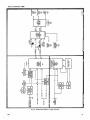
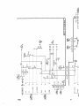
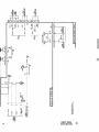
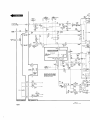
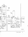
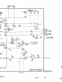
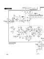
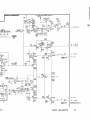
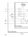
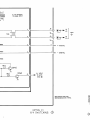
Circuit diagrams are given on foldout pages in Section 8.
The component number and electrical value of each component in this instrument is shown on the diagrams .
Components that are mounted on circuit boards are outlined on the diagrams with a heavy black line .
Wiring Color Code
Voltages and Waveforms
Semiconductor Basing
Typical operating voltages are shown on the diagrams .
Voltage Conditions given on the diagram page indicate the
test equipment used and the front-panel control status
necessary to obtain the given voltages .
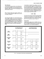
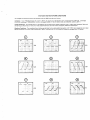
Typical operating waveforms are shown next to the diagram
where they were measured . Each waveform is numbered to
locate on the diagram the point where the waveform was
taken . Waveform Conditions given on the diagram page list
the test equipment used and the front-panel control status
necessary to obtain the given waveform .
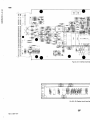
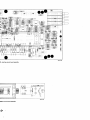
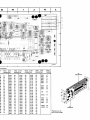
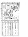
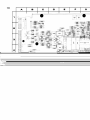
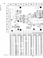
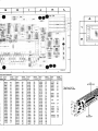
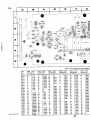
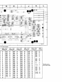
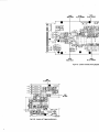
Circuit-Board Illustrations
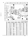
Circuit-board illustrations are shown on the foldout page
preceding the associated diagram . Each board-mounted
electrical component is identified by its circuit number, as
are interconnecting wires and connectors .
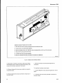
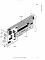
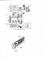
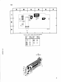
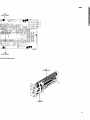
Figure 8-2, in the front of the diagrams section, shows the
location and assembly number of each circuit board in this
instrument .
Switch Cam Identification
Switch cam numbers shown on diagrams indicate the position of each cam in the complete switch assembly . The
switch cams are numbered from front to rear .
Diode Color Code
The cathode end of each glass-encased diode is indicated by
a stripe, a series of stripes, or a dot. The cathode and anode
ends of metal-encased diodes are identified by the diode
symbol marked on the case . For most silicon or germanium
diodes with a series of stripes, the color code identifies the
Insulated wire and cable used in this instrument is colorcoded to facilitate circuit tracing.
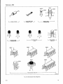
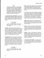
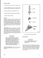
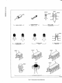
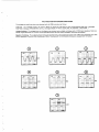
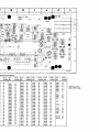
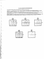
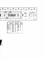
Figure 4-2 illustrates the basing configurations for all semiconductors used in this instrument . Some plastic-case
transistors have lead configurations that do not agree with
those shown here . If a replacement transistor is made by a
different manufacturer than the original, check the manufacturer's basing diagram. All transistor sockets in this
instrument are wired for the standard basing used for metalcase transistors .
Inter-Board Pin Connector Identification
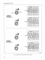
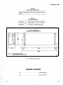
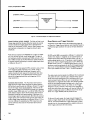
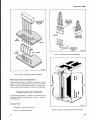
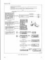
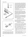
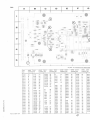
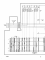
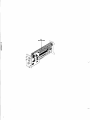
The inter-board pin connector sockets are installed on circuit boards, in groups of 5 sockets (as in Figure 4-3) .
Socket number 1 is indexed on the circuit board with either
a triangular mark or the number 1 . Each group of sockets is
identified by its J (jack) number etched on the circuit
board . The J numbers correlate to the J (jack) and P (plug)
circuit numbers on the schematic diagrams .
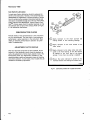
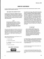
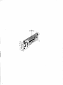
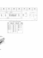
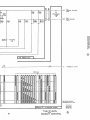
Multi-Pin Connector Identification
Multi-pin connectors mate with groups of pins soldered to
circuit boards . Pin number 1 is indexed with a triangular
mark on the circuit board and molded on the holder of the
multi-pin connector, as shown in Figure 4-4. Each group of
pins is identified by its corresponding J number etched on
the circuit board . The J numbers, on the circuit boards,
correlate to the J and P component numbers on the schematic diagrams .
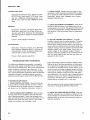
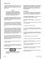
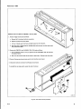
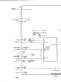
Interface Connector Pin Locations
The Interface circuit board couples the plug-in unit to the
associated mainframe (oscilloscope) . Figure 4-5 identifies
the pins on the interface connector as shown on Interface
Connectors and Power Supply diagram 8 in the Diagrams
section.
4- 3