1
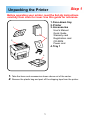
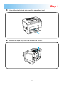
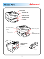
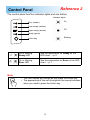
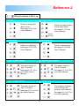
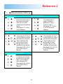
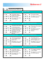
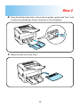
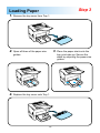
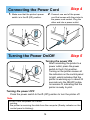
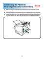
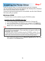
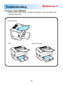
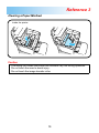
PageWorks 18L
Contents
Step 1
Unpacking the Printer ..................... 1
Reference 1
Printer Parts ..................................... 3
Reference 2
Control Panel ................................... 4
Step 2
Attaching the Face-Down Tray
and Tray 1....................................... 11
Step 3
Loading Paper................................ 13
Step 4
Connecting the Power Cord ......... 14
Step 5
Turning the Power On/Off ............. 14
Step 6
Connecting the Printer to the
Computer (Local Connection) ...... 15
Step 7
Installing the Printer Driver .......... 16
Reference 3
Troubleshooting ............................ 18
Step 1
Unpacking the Printer
Before operating your printer, read the Set-Up Instructions
carefully from cover to cover. Use this guide for reference.
1. Face-down tray
2. Printer
3. Accessories
1
3
2
User’s Manual
Quick Guide
Warranty card
Registration card
CD-ROM
Power cord
4. Tray 1
4
1.
2.
Take the items and accessories shown above out of the carton.
Remove the plastic bag and peel off the shipping tape from the printer.
1
Step 1
3.
Pull out the plastic-lead strip from the paper feed inlet.
4.
Remove the tape strip from the back of the printer.
2
Reference 1
Printer Parts
Control panel
Face-down tray
Paper size guide
Manual feed tray
Tray cover
Top cover release
button
Paper size guide
Power switch
Tray 1
(multipurpose tray)
Parallel interface
connector
Power cord socket
Imaging
cartridge
3
Reference 2
Control Panel
The control panel has four indicator lights and one button.
Indicator lights
On
Error (amber)
Toner empty (amber)
Paper empty (amber)
Off
Ready (green)
Blinking
Action key
On or blinking
Ready LED
See the explanation for Ready on the
LED chart. ☞p. 5
On or blinking
Error LED
See the explanation for Error on the LED
chart. ☞p. 7
Note
• The LED display will change as you press the Action key.
• The appearance of this icon throughout this manual indicates
when you need to press the Action key.
4
Reference 2
When the Ready LED is on
Ready
Power Save
Printer is ready and
able to print.
See page 6-16 of the
User’s Manual.
Printer has entered the
Power Save Mode.
See page 6-17 of the
User’s Manual.
Slowly
blinking
Initializing
Warming Up
Printer is warming up.
See page 6-16 of the
User’s Manual.
Power on, initializing.
See page 6-16 of the
User’s Manual.
Tray 1 Paper Empty
Tray 2 Paper Empty
The paper supply of
Tray 2 is empty.
See page 3-7 or 6-18 of
the User’s Manual.
The paper supply of
Tray 1 is empty.
See page 2-10, 3-4 or
6-18 of the User’s
Manual.
Tray 3 Paper Empty
Toner Low
The paper supply of
Tray 3 is empty.
See page 3-7 or 6-18 of
the User’s Manual.
The imaging cartridge
is low on toner but
printing is still possible.
See page 5-1 or 6-17 of
the User’s Manual.
5
Reference 2
When the Ready LED is on
Wait Action
Size Mismatch
The wrong size of
paper has been
detected in Tray 1,
Tray 2 or Tray 3.
See page 3-1, 4-50 or
6-18 of the User’s
Manual.
Press the Action key in
the event of a paper
size error or when
operating in the manual
mode.
See page 6-17 of the
User’s Manual.
Tray 2 No Cassette/No Tray 2
Tray 3 No Cassette/No Tray 3
The cassette for Tray 3
is not in place or a print
job was sent using the
Tray 3 setting in the
printer driver, even
though Tray 3 is not
installed on the printer.
See page 2-22, 4-51 or
6-19 of the User’s
Manual.
The cassette for Tray 2
is not in place or a print
job was sent using the
Tray 2 setting in the
printer driver, even
though Tray 2 is not
installed on the printer.
See page 2-22, 4-51 or
6-19 of the User’s
Manual.
Duplex Unit Not Available
A duplex print job has
been sent to a printer
that is not equipped
with a duplex unit.
See page 4-56, 4-59 or
6-19 of the User’s
Manual.
6
Reference 2
When the Error LED is on
Buffer Overflow
Cover Open
The cover is open.
See page 1-3 or 6-20 of
the User’s Manual.
The buffer cannot
handle the volume of
data being sent.
See page 6-20 of the
User’s Manual.
Paper Size Error
Cover Open (Duplex Unit)
The paper-size setting
of the printer driver
does not match the size
of paper that has been
detected in the tray.
See page 3-1, 4-50 or
6-20 of the User’s
Manual.
The cover of the duplex
unit is open.
See page 2-19, 6-9 or
6-23 of the User’s
Manual.
Wrong Media (Duplex Unit)
Wrong Size (Duplex Unit)
The wrong size of
paper has been loaded
into the duplex unit.
See page 3-16 or 6-23
of the User’s Manual.
The wrong media has
been loaded into the
duplex unit.
See page 3-16 or 6-23
of the User’s Manual.
Video Under Run
Replace Imaging Cartridge
The imaging cartridge
is out of toner.
See page 5-1 or 6-24 of
the User’s Manual.
The buffer cannot
handle the volume of
data being sent.
See page 6-24 of the
User’s Manual.
7
Reference 2
When the Error LED is on
Paper Misfeed 1
Paper Misfeed 2
A paper misfeed
occurred near Tray 2.
See page 6-8 or 6-21 of
the User’s Manual.
A paper misfeed
occurred near the
multipurpose tray.
See page 6-7 or 6-21 of
the User’s Manual.
Paper Misfeed 3
Paper Misfeed 4
A paper misfeed
occurred near Tray 3.
See page 6-8 or 6-21 of
the User’s Manual.
A paper misfeed
occurred near the
manual feeding tray.
See page 6-7 or 6-21 of
the User’s Manual.
Paper Misfeed 5
Paper Misfeed 6
A paper misfeed
occurred near the
imaging cartridge.
See page 6-2 or 6-22 of
the User’s Manual.
A paper misfeed
occurred near the
lower-duplex unit.
See page 6-9 or 6-22 of
the User’s Manual.
Paper Misfeed 7
Paper Misfeed 8
A paper misfeed
occurred near the
upper-duplex unit.
See page 6-9 or 6-22 of
the User’s Manual.
A paper misfeed
occurred near the
fuser.
See page 6-2 or 6-22 of
the User’s Manual.
8
Reference 2
When the Error LED is on
I/O Error (Parallel)
I/O Error (Network)
A network port error
occurred.
See page 6-24 of the
User’s Manual.
A controller error
occurred at the parallel
port.
See page 6-24 of the
User’s Manual.
9
Reference 2
Fatal Error
Requires servicing.
Turn the power to the printer off and then on again. If the same LED message continues to be displayed, contact your local Minolta Technical Support.
When the Error LED is on
HSYNC Abnormal
Polygonal Mirror Motor
Main Motor
Fuser Low Temperature
Fuser Overheat
SRAM, DRAM, ROM,
Engine I/F, CPU
Fuser Warm Up
Fuser Fan
P/H Fan
10
Attaching the Face-Down Tray
and Tray 1
1.
Step 2
With both hands, gently bend the face-down tray inwards and insert one of
its tabs into its holder on the upper portion of the printer. Continue to bend
the face-down tray so that it curves enough for the second tab to fit into its
holder and release the tray into position.
Note
• Be sure to close the face-down tray before opening the top cover to prevent
injuries.
11
Step 2
2.
Using the left and right slots in the printer as guides, gently push Tray 1 until
it cannot be inserted any further (as shown in the illustration).
3.
Attach the tray cover onto Tray 1.
12
Step 3
Loading Paper
1.
Remove the tray cover from Tray 1.
2.
Open all three of the paper size
guides.
4.
Replace the tray cover onto Tray 1.
3.
13
Place the paper stack onto the
tray, print-side up. Secure the
stack by adjusting the paper size
guides.
Connecting the Power Cord
1.
2.
Make sure that the printer’s power
switch is in the O (Off) position.
Step 4
Connect one end of the power
cord that comes with the printer to
the power cord socket. Plug the
other end into a power outlet.
Turning the Power On/Off
Step 5
Turning the power ON
After connecting the printer to a
power outlet, press the power
switch to the I (On) position.
Turning on the printer causes all
the indicators on the control panel
to light, which indicates that the
printer is warming up. In about 23
seconds only the READY indicator remains lit, indicating that the
printer is ready to print.
Turning the power OFF
Press the power switch to the O (Off) position to turn the printer off.
Note
DO NOT turn the power OFF while:
• printing
• the printer is receiving the data from the computer (Ready indicator on the
control panel is blinking)
14
Connecting the Printer to
Step 6
the Computer (Local Connection)
1.
Make sure that the printer and the computer you are connecting it to are
both turned off.
2.
3.
Connect one end of the interface cable to the parallel port of the computer.
Connect the other end of the cable to the parallel connector on the back of
the printer. Secure the cable using the two clips on the parallel connector.
15
Installing the Printer Driver
Step 7
Install the printer driver to control the printer from your computer.
You can install the printer driver for Windows 95, Windows 98 or Windows
NT 4.0 from the Printer Driver CD-ROM.
Follow the instructions below and for more details, see the User’s Manual
that came with your printer.
Windows 95/98
The printer driver must be installed using the CD-ROM’s installer.
Installing from the CD-ROM (Auto Run)
1. Turn on your computer and start up Windows 95 or Windows 98.
2. Insert the Printer Driver CD-ROM into your computer’s CD-ROM drive.
3. The opening screen is automatically displayed. Click on the GDI Printer
Driver menu to start the installer.
Note
• The configuration of some computers may prevent the opening screen
from appearing automatically. If the screen does not appear, double-click
setup.exe in the CD-ROM.
• The printer driver must be installed using the CD-ROM’s installer. Do not
use the Add Printer wizard from the Printers folder. Installation through the
Add Printer wizard will prevent the printer from performing properly.
After installing the printer driver, the Minolta PageWorks/Pro 18L printer
icon appears in the Printers folder.
16
Step 7
Windows NT 4.0
Installing from the CD-ROM (Auto Run)
1. Turn on your computer and start up Windows NT 4.0.
2. Insert the Printer Driver CD-ROM into your computer’s CD-ROM drive.
3. The opening screen is automatically displayed. Click on the GDI Printer
Driver menu to start the installer.
Note
• The configuration of some computers may prevent the opening screen
from appearing automatically. If the screen does not appear, double-click
setup.exe in the CD-ROM.
• The printer driver must be installed using the CD-ROM’s installer. Do not
use the Add Printer wizard from the Printers folder.
After installing the printer driver, the Minolta PageWorks/Pro 18L printer
icon appears in the Printers folder.
For details, refer to Chapter 4 of the User’s Manual.
17
Reference 3
Troubleshooting
Clearing a Paper Misfeed
Remove the misfed sheet of paper by pulling it in the direction indicated by the arrow.
Face-down tray
Tray 1
Manual feed tray
18
Reference 3
Clearing a Paper Misfeed
Inside the printer
Caution
• The fusing unit inside the printer can become very hot during operation.
Do not touch the area to avoid injury.
• Do not touch the image transfer roller.
19
Reference 3
Solving Print Quality Problems
• Remove the imaging cartridge and gently shake it a few times to distribute remaining toner.
• Remove the imaging cartridge and check it for damage. Replace the
imaging cartridge with a new one if necessary.
• Clean the inside of the printer. (Refer to the User’s Manual.)
For more details, refer to the “Troubleshooting” and “Maintenance” sections of the User’s
Manual.
No output
•
•
•
•
Make sure that the printer is plugged in.
Make sure that power is turned on.
Make sure that you are using the correct type of printer cable.
Make sure that your computer’s communication port settings are correct.
For more details, refer to the User’s Manual.
20
MEMO
MEMO
MEMO
Copyright
1999 MINOLTA CO., LTD
Printed in Japan
The information contained in this manual is
subject to change without notice to
incorporate improvements made on the
product or products the manual covers.
Minolta CO., LTD. Image Information Products Marketing Headquarters, 3-13, 2-chome, Azuchi-machi, Chuo-ku, Osaka. 541-8556, Japan
1999. 3
4110-7750-01