1
2SWLRQDO6HULDO
,QWHUIDFH
1
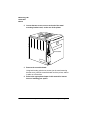
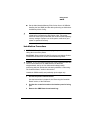
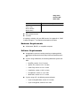
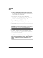
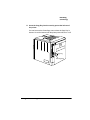
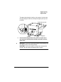
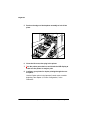
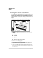
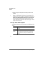
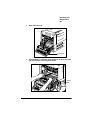
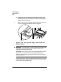
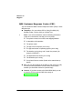
Turn off the printer, and then disconnect the power cord and
all interface cables (parallel and Ethernet) from the printer.
2
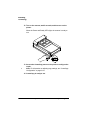
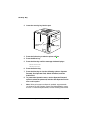
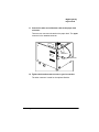
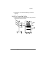
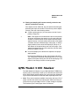
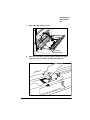
Access the printer controller board.
Use the instructions in chapter 2, “Memory and System Software”
the “Removing the Controller Board” section, of this manual.
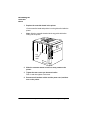
3
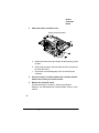
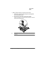
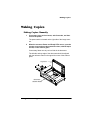
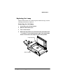
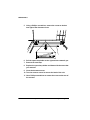
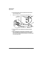
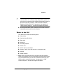
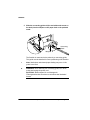
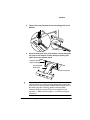
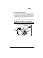
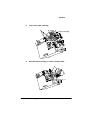
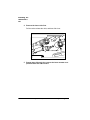
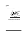
Remove the two screws from the optional interface plate.
Save the two screws. (You’ll use them when you install the
optional interface card.) You can either save or discard the plate.
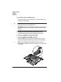
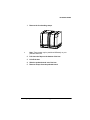
4
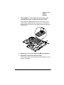
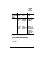
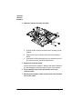
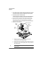
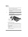
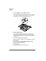
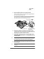
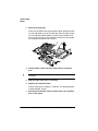
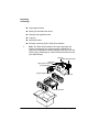
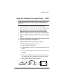
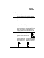
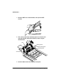
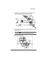
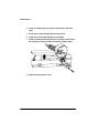
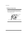
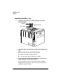
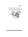
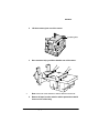
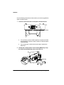
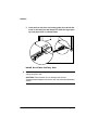
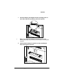
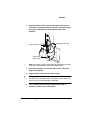
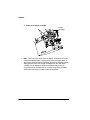
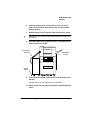
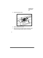
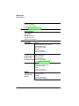
Attach the serial interface.
6HULDOFRQQHFWRUV
5LEERQ
&DEOH
6HULDO
&RQQHFWRU
3LQV
6HULDO
3RUW
.......
............ ....
...... ...
...... ...... .....................
...
...... ......
.................. .....................
... ...
...............
......
............
............
............
............
............
............
.........
............
...............
▲
a
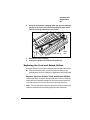
Position the serial connectors directly over the serial
connector pins on the controller board.
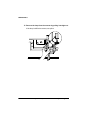
b
Snap the serial connectors directly onto the serial connector pins.
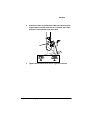
c
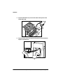
Press down on the connector gently until it is firmly seated on
the connector pins.
Caution: Do not push or pull from the ribbon cable. Use the
cable connector.
406785%23ULQW6\VWHP2SWLRQV