1
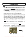
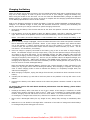
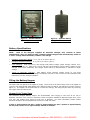
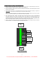
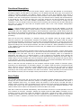
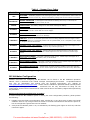
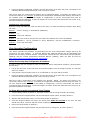
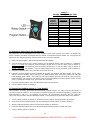
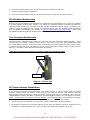
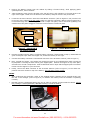
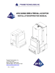
AC401 Battery Powered Changer Operations Manual For more information visit www.Gumball.com | 800-260-0010 | +1-214-550-5079 Specifications Operating voltage 12VDC Battery type Sealed Lead-Acid Power consumption Operating maximum – 20W Standby – 20mW Battery life 8-12 weeks on full charge Hopper dispense rate Approximately 3 coins/second Operating temperature 0-140 degrees Fahrenheit Hopper coin capacity 100 coins minimum to 1,600 coins maximum Warranty Information A Return Material Authorization number (RMA #) must be obtained before returning a unit for repair. A copy of invoices must accompany any and all warranty work. It is the end users’ responsibility to follow cleaning and maintenance procedures as outlined in the validator manual. Any unit returned for repair requiring only a cleaning will be charged a flat rate plus shipping and handling. Validators Validators (AC401) are warranted for two years from date of purchase. Coin Acceptor The Coin Acceptor (AC401-COIN) is covered by a one-year warranty from date of purchase. Battery The Battery is covered by a one-year Limited Warranty. Battery Hopper The Battery Hopper is covered by a five-year Limited Warranty from date of purchase. COVERED • Manufacturers’ defects in workmanship or materials NOT COVERED • • • • • • Damage caused by shipping or physical abuse Misapplication Vandalism End users’ attempt, on their own, to repair components Cleaning and maintenance Power surges and lightning strikes 3 For more information visit www.Gumball.com | 800-260-0010 | +1-214-550-5079 Table of Contents SECTION A: SET-UP & INSTALLATION Setup ............................................ Charging the Battery 5 ................................. 6 ............................... 7 Filling the Battery Hopper . . . . . . . . . . . . . . . . . . . . . . . . . . . . . . . . 7 Pushbutton . . . . . . . . . . . . . . . . . . . . . . . . . . . . . . . . . . . . . . . . . . 9 Using the Hopper Dump Feature .......................... 9 Payout Selection . . . . . . . . . . . . . . . . . . . . . . . . . . . . . . . . . . . . . . 9 Battery Specifications Functional Description ................................ 10 Error Codes . . . . . . . . . . . . . . . . . . . . . . . . . . . . . . . . . . . . . . . . . . 10-11 Bill Validator Configuration . . . . . . . . . . . . . . . . . . . . . . . . . . . . . . . 11-12 Coin Acceptor Configuration . . . . . . . . . . . . . . . . . . . . . . . . . . . . . . 12-14 Bill Validator Maintenance Coin Acceptor Maintenance ............................... 14 .............................. 14 AC Power Harness Installation ............................ 14-15 SECTION B: PARTS LIST AC401/AC401-COIN Parts List. . . . . . . . . . . . . . . . . . . . . . . . . . . . . . . . . 16 4 For more information visit www.Gumball.com | 800-260-0010 | +1-214-550-5079 SECTION A SETUP & INSTALLATION Setup 1. Fully unpack all of the boxes that accompany this changer. This should include the box containing the changer and this manual, the box containing the battery, and any extra boxes that may contain the Bill Box, Battery Charger, or additional spare batteries, etc. 2. Open the door to the changer. For the Cam Lock, use the keys that are enclosed in the manila envelope accompanying this manual. Insert the key, and then rotate it clockwise ¼ turn to unlock the door. For the T-handle, the lock is not installed yet (refer to step 9 for lock installation). Turn the handle counter-clockwise, up to 10 times or more, until the screw disengages from the lock bracket. 3. Visually inspect the changer’s interior for any obvious damage that may have occurred during shipping, including dislodged components or detached connectors. NOTE: The white two-position battery connector will be detached, as the battery is shipped in a separate box. 4. If no damage is found, install the battery in the cabinet. The battery should be placed on top of the metal platform located in the top left corner of the cabinet, above the Battery Hopper. 5. Before permanent installation of your AC401 changer, perform a functional test to further verify that there is no hidden shipping damage. To ready the changer for use, coins must first be added to the hopper. You will need at least enough coins to cover the two metal plates at the bottom of the Coin Bin, or approximately 100-150 coins. The Battery Hopper must also be powered-up. Connect the white two-position battery connector, which is secured to the left side of the cabinet, to the mating white connector attached to the top of the battery (refer to Figure 1 below). When this connection is made, the hopper’s red LED should light up for approximately two seconds. When the LED turns off, the changer is ready for testing. 6. AC401: Insert the Bill Box inside the changer. It should slide in to the right of the hopper, with its bottom resting on the two studs protruding from the right interior wall. The part on the top of the Bill Box that sticks out toward the left should be covering the hopper’s Coin Bin to block accepted bills from falling into it. AC401-COIN: Insert the Coin Box inside the changer. It should fit into the space on the bottom of the cabinet to the right of the hopper, underneath the coin acceptor. When the changer’s front door is closed, all accepted coins should fall down directly into the Coin Box. 7. Close the front door, and insert a few bills or coins to ensure the machine pays out correctly. To change the payout, refer to the “Payout Selection” section of this manual. 8. Once the changer has been tested and is working properly, please completely charge the battery before installing the changer in its permanent location. 9. Installing the T-handle lock: The lock and keys can be found inside the manila envelope accompanying this manual. To install the lock, insert the cylinder into the round hole in the middle of the T-handle, pushing it all the way in until it stops. Rotate the cylinder until you hear it ‘snap’ into place. Turn the key counterclockwise ¼ turn, and remove the keys. FUSE CONN ECT To Battery To Battery Hopper Figure 1 – Battery (top view) 5 For more information visit www.Gumball.com | 800-260-0010 | +1-214-550-5079 Charging the Battery When your AC401 arrives from the factory, the 12V Sealed Lead Acid (SLA) battery supplied with the unit may not be fully charged. In order to get the most use out of your changer, charge the battery fully before using the AC401 for the first time. You can use either the Standard Battery Charger, the Optional Battery Charger, or another of your choice, as long as it complies with the charging specifications detailed in the “Battery Specifications” section of this manual. Refer to the following procedure to charge the battery if using the supplied Standard or Optional Battery Chargers. If a different charger is used, read the directions written for removing and reinstalling the battery, and consult your charger’s manual for specific charging instructions. 1. Disconnect the battery from the Main Harness at the white two-position connector located on top of the battery. 2. Lift the battery up from the platform above the Battery Hopper, and slide it sideways, toward the right. Once it is free of the platform and the lock bracket assembly, remove it from the cabinet. NOTE: The battery should be charged in a well-ventilated area. enclosed space. Do not charge the battery in an 3. With the battery charger unplugged, connect its white connector to the white two-position connector that is attached to the battery terminals. NOTE: If your charger has alligator clips, attach the black one to the negative (-) battery terminal and the red one to the positive (+) terminal. In order for current to flow, the clips must make contact with the battery’s metal terminals; so, loosen – but do not remove – the connectors, if necessary. 4. Once the charger is properly connected to the battery, plug it into an AC outlet to begin charging. NOTE: The Standard Charger can only accept 120V (± 15V), but the Optional Charger can accept any AC voltage in the range 90V–264V. For the Standard Charger, the RED “Charging” LED will be ON solid during charging. Continue charging until the GREEN “Charged” LED turns ON solid, at which time charging is complete (refer to Figure 2). There is only one indicator LED on the Optional Charger, but it operates the same way – RED means “Charging,” and GREEN means “Charged” (refer to Figure 3). Charging times depend on the extent that the battery has been discharged and may take up to 24 hours or more for a 100% discharged battery. Both the Standard and Optional Battery Chargers may remain plugged in while connected to the battery for any length of time without harming the battery. Once charging is complete, the chargers enter a “Float” charging mode in order to maintain the battery in a completely charged state, but without overcharging it. 5. When charging is complete, unplug the charger from the wall, and detach its white connector from the battery. 6. Carefully lift the battery up, and slide it back into place on the platform in the top left corner of the cabinet. 7. Reconnect the battery to the Main Harness at the white two-position connector located on top of the battery. To prolong the service life and obtain maximum performance from the battery, please follow these guidelines: • Recharge the battery after it has been in use for 8-12 weeks. If the changer is installed in a colder and/or busier location, recharge it closer to the 8th week; if it is installed in a warmer and/or slower location, charging can wait until closer to the 12th week. NOTE: It is recommended that the battery be recharged, or swapped with a fresh one, whenever the machine is refilled or serviced. • Never store a discharged battery for any length of time; always fully recharge it immediately after use. • Batteries not in use should be recharged after a maximum of 9 months of storage and should always be recharged fully before being put into service. 6 For more information visit www.Gumball.com | 800-260-0010 | +1-214-550-5079 Figure 2 – Standard Battery Charger (120V only) Figure 3 – Optional Battery Charger w/Universal Input Battery Specifications NOTE: Both of the chargers supplied by American Changer fully conform to these specifications. They are both two-step, constant voltage chargers that automatically switch to a “float” voltage when the battery reaches a full charge. • Operating Temperature Range: 0° F (-18° C) to 140° F (60° C) • Charging Temperature Range: 0° F (-18° C) to 122° F (50° C) • Cycle Charging: Limit current to 2.4A. Charge until battery voltage (under charge) reaches 14.4– 15.0V at 68° F (20° C). Hold at 14.4–15.0V until the current drops to under 120mA. Battery is fully charged under these conditions, and charger should either be disconnected or switched to “float” voltage. • “Float” or “Stand-By” Charging: Hold battery across constant voltage source of 13.5–13.8V continuously. When held at this voltage, the battery will seek its own current level and maintain itself indefinitely in a fully-charged condition. Filling the Battery Hopper The AC401 will not operate if the hopper is empty. There must be at least enough coins in the hopper to cover the two gold-colored metal plates at the bottom of the Coin Bin for the changer to function (refer to Figure 4). The hopper can be filled while it is inside the changer, but filling may be easier by removing the hopper from the cabinet first. Hopper Coin/Token Sizes The American Changer Battery Hopper will accommodate coins ranging in size from 21–30 mm in diameter, and from 1.25–3.3 mm in thickness. There are options available to dispense larger coins, up to 31.5 mm, and smaller coins, down to 16.25 mm, in diameter. For more information, please contact American Changer’s Service Department toll free at 1-888-741-9840. A dime is approximately 18 mm; a nickel is approximately 21 mm; a quarter is approximately 25 mm; and a dollar coin is approximately 28 mm in diameter. 7 For more information visit www.Gumball.com | 800-260-0010 | +1-214-550-5079 Hopper Removal, Filling, and Replacement 1. Before removing the hopper from the cabinet, turn off the power by disconnecting the white twoposition connector located on top of the battery (refer to Figure 1). 2. Remove the Battery Hopper from the cabinet by sliding it forward slowly, while applying gentle upward pressure, until it releases. 3. Fill the hopper with coins; it can be filled all the way to the top. The hopper capacity in quarters is 1,600 coins (± 10% due to the random way the coins settle inside the bin). NOTE: When filling the hopper, do not allow any bent coins or foreign objects to enter the Coin Bin. These may cause the hopper to jam, rendering the changer inoperable. 4. Next, reinstall the hopper. NOTE: The hopper will be quite heavy when it is full, so take additional care when placing it back inside the AC401 cabinet. The hopper has mounting grooves on its underside that match up with the keyed pattern cut along the sides of the green hopper plate. Position the hopper on top of the plate, and maneuver it until it drops down. Slide it backwards until it stops, and the hopper plate’s connector inserts into the hopper’s 12-pin connector. 5. Finally, reconnect the main harness’ white two-position connector to the mating connector located on top of the battery. The changer will power up and be ready to use. Hopper Coin Bin (Pour the coins into this opening) Pushbutton LED Indicator Coin Counting Optical Sensor 12-Pin Connector (Connector is shown on reverse side of actual for detail) 123456 Bill/Coin Meter Mounting Grooves Figure 4 – Battery Hopper 8 For more information visit www.Gumball.com | 800-260-0010 | +1-214-550-5079 Pushbutton The Pushbutton on the Battery Hopper is used for several purposes. It is used primarily to control the hopper “Dump” feature, but it is also used when configuring the Bill Validator or Coin Acceptor as well as for clearing some error codes. For configuration instructions, please refer to the Bill Validator Configuration or the Coin Acceptor Configuration sections in this manual. An Error Codes section can also be found in this manual. Coin “Dump” instructions follow below. Using the Hopper Dump Feature A coin “Dump” is a way to remove all of the coins/tokens from the hopper without having to remove the hopper from the machine. During a “Dump,” the hopper’s motor is turned on, and coins are allowed to dispense continuously until it is either manually stopped or the hopper empties completely. NOTE: Please be aware of the state-of-charge of the battery when performing a coin dump, and use caution. During a coin dump, the hopper motor is running continuously, which discharges the battery at a much faster rate than normal operation of the changer. Do not perform a coin dump using a battery that is already low, as over-discharging may damage it, shortening its service life. Dump Procedure 1. Before you begin the coin Dump, open the changer door to give access to the front of the hopper. 2. Place a suitable container in front of the hopper to catch the dispensed coins. 3. Locate the Pushbutton in the top right corner of the hopper. Press and hold the Pushbutton for approximately four seconds until the hopper motor begins to run and then release it. NOTE: The red LED should turn ON while the Pushbutton is being held down, and then turn OFF when the dumping starts. 4. To stop the Dump at any time, press the Pushbutton once. The motor will stop running immediately, and the Battery Hopper will return to the normal operating mode. Payout Selection Unless otherwise specified at the time of ordering, the changer will be configured to dispense four coins per dollar from the hopper. These can be either U.S. quarters, or tokens valued at $0.25, as long as they are within the specified size limits detailed in the “Hopper Coin/Token Sizes” section in this manual. The Battery Hopper can also be configured to dispense one coin per dollar. These also can be either U.S. $1 coins, or tokens valued at $1.00, as long as they are within the specified size limits detailed in the “Hopper Coin/Token Sizes” section in this manual. To change the payout, locate the connector on the right side of the hopper through the vertical slot cut out of the plastic sidewall. Reposition the shunt, or jumper, onto the bottom two pins of the connector, as seen in Figure 5 below. NOTE: If there is no shunt installed on the hopper’s side connector, the payout will default to four coins per dollar. Standard Electronics Shunt/Jumper Shunt/Jumper with Handle 4 Coins 1 Coin Per Dollar Per Dollar Figure 5 – Side Connector 9 For more information visit www.Gumball.com | 800-260-0010 | +1-214-550-5079 Functional Description There are three primary parts inside of the AC401 changer. These are the Bill Validator or Coin Acceptor, the Battery Hopper, and the Battery. The battery is a 12V Sealed Lead-Acid (SLA) type, and it powers the changer’s complete operation. The Battery Hopper holds the coins and dispenses them during a transaction. The Circuit Board that controls the entire machine is also located inside the hopper. The Bill Validator scans the incoming bills to determine if they are authentic and to identify their denominations. It can accept $1, $5, $10, and $20 bills, but it will only accept $1s and $5s by default; the rest are “disabled.” Please refer to the “Bill Validator Configuration” section in this manual to change the bill acceptance. The Coin Acceptor works the same way by examining the incoming coins for both authenticity and value. To change the coins that are accepted, please refer to the “Coin Acceptor Configuration” section in this manual. AC401: A typical changing operation begins with a bill being inserted into the Bill Validator. As the bill enters the validator’s front bezel, a sensor detects it, and the system is powered up. Approximately one second later, after the validator has finished its internal powering-up procedure, the bill will be drawn into the acceptor to be examined for authenticity. The power-up procedure is fast enough that a bill should be able to enter the front bezel, trigger the sensor, and continue uninterrupted straight into the validator for processing. Once the bill has been “validated,” or deemed genuine, the validator sends the proper number of electronic pulses for the denomination accepted to the Battery Hopper. The hopper reads the pulses, increments the Bill Meter, and then turns on the motor to begin dispensing coins. As they exit, the coins pass an optical sensor and are counted. When the correct number of coins have been dispensed from the hopper according to the current payout selection, the motor is turned off. Shortly afterward, if the sensor in the validator’s front bezel has detected no further bills, the validator will be powered down in order to prolong battery life. AC401-COIN: A typical changing operation begins with the Coin Door being lifted. A sensor detects when this occurs, and the system is powered up. A coin is then inserted into the slot on the front of the machine to the right of the Coin Door. The coin is directed into the Coin Acceptor, where it is examined for authenticity and value. If it is deemed genuine, it will be allowed to fall straight down through the acceptor into the metal Coin Box. If it is either a coin not accepted by the machine or any other “slug” or foreign object, the Coin Acceptor will divert it through its reject chute to the external Coin Cup for return to the customer. The power-up procedure is fast enough that a coin inserted immediately after the door is lifted should be able to be processed properly by the Coin Acceptor. Once a valid coin has been accepted, the Coin Acceptor sends the proper number of electronic pulses, according to its denomination, to the Battery Hopper. The hopper reads the pulses, increments the Bill Meter, and then turns on the motor to begin dispensing coins. As they exit, the coins pass an optical sensor and are counted. When the correct number of coins have been dispensed from the hopper according to the current payout selection, the motor is turned off. Shortly afterward, if the Coin Door has been allowed to reclose, the Coin Acceptor will be powered down in order to prolong battery life. Error Codes The red LED located at the top of the front side of the Battery Hopper indicates the changer’s status through the use of flash codes. While the machine is working properly, the LED Indicator will deliver a single “heartbeat” flash every 7.5 seconds. When the machine is out-of-service, the LED will flash a specific number of times in order to indicate the error that occurred. Error Codes are signaled at a rate of 2 flashes per second, and are repeated continually, with a 1.5 second break between repetitions, until cleared. Please refer to Table 1 for descriptions of all of the LED’s error codes. Most Error Codes will be cleared automatically, and the machine will return to normal operation once the error condition is removed. Example: Refilling the hopper while the LOW COINS (2 Flashes) error is indicated. However, some Error Codes are “latched” by the hopper. To clear these codes, a single press of the Pushbutton located to the right of the LED is required, in addition to the removal of the error condition. In Table 1, asterisks (*) denote the Error Codes that require a Pushbutton press for clearing. 10 For more information visit www.Gumball.com | 800-260-0010 | +1-214-550-5079 Table 1 – Hopper Error Codes Red LED Description OFF NO POWER – The Battery Hopper is not receiving any power and is not operational. Please make sure the hopper is pushed in all the way, and check the battery voltage and all of the harness connections. “Heartbeat” 1 Flash NORMAL OPERATION – If the hopper’s LED Indicator is flashing once every 7.5 seconds, the machine is working properly and is ready for use. LOW VOLTAGE – The battery voltage is too low. Please recharge the battery. 2 Flashes LOW COINS – There are not enough coins in the hopper to cover the two metal plates at the bottom of the hopper’s coin bin. Please add coins to the hopper. 3 Flashes BLOCKED EXIT SENSOR – The optical sensor located at the hopper’s coin exit is being blocked. Please inspect the area and remove the blockage. 4 Flashes* TIME-OUT – An error occurred that prevented coins from being dispensed from the hopper. Please inspect the hopper for a mechanical problem such as a jammed belt, or for a completely empty hopper or “bridged” coins in the Coin Bin. 5 Flashes INCIDENT LIGHT: EXIT SENSOR – Incident light has been detected shining on the hopper’s coin exit sensor. Please inspect the area and remove any external light source. 6 Flashes INCIDENT LIGHT: BILL SENSOR – Incident light has been detected shining on the bill sensor mounted inside the validator’s front bezel. Please inspect the area and remove any external light source. 7 Flashes* MOTOR OVER-CURRENT – The motor is drawing excess current. Please inspect the hopper for a jammed belt, or for a damaged motor, wire, or circuit board. 8 Flashes* MOTOR UNDER-CURRENT – The motor is drawing insufficient current. Please inspect the hopper for a disconnected motor, or for a damaged motor, wire, or circuit board. 9 Flashes BILL SENSOR OBSTRUCTED – The bill sensor mounted inside the validator’s front bezel has been continually obstructed for over 1 minute. Please inspect the bill entrance and remove any obstruction. * This error must be cleared by pressing the Pushbutton. Bill Validator Configuration Detailed instructions for configuring the Bill Validator can be found in the Bill Validator’s Operation Manual, which is enclosed in the manila envelope accompanying this manual. An Operation Manual may also be downloaded and printed from the Pyramid Technologies, Inc. website at www.pyramidacceptors.com/support.html. Please read the Validator’s Operation Manual carefully before attempting to reconfigure the validator. Presented here are only instructions for filling out the Configuration Card as well as instructions for what must be done to the Battery Hopper before performing the procedure. Before Performing the Configuration Procedure In order to keep the Bill Validator’s power on during the entire configuration procedure, please perform the following: 1. Partially insert the filled-out Configuration Card, a dollar bill, or any other piece of paper into the Bill Validator. Insert it only enough so that the sensor in the front bezel detects it and turns the power on, but not enough that it gets drawn into the validator. 2. Verify that the validator power is on, as indicated by the flashing green lights on the front, and then remove the paper. 11 For more information visit www.Gumball.com | 800-260-0010 | +1-214-550-5079 3. Press the hopper’s Pushbutton, located in the top right corner of the front side, once. The hopper’s red Indicator LED should begin blinking at a rate of once per second. Once this is done, the configuration procedure can be completed. NOTE: The hopper will remain in the “Power ON” state for only 1 minute, so perform the configuration immediately after entering this mode. If the validator power turns off in the middle of configuration, it will be unsuccessful and must be reconfigured from the beginning. To take the hopper out of the “Power ON” state before the minute is up, press the Pushbutton once again. Configuration Card Settings Both the Trilogy and APEX/XLC cards are laid out the same, so make the following selections when filling out either: Section 1 – “Pulse” (Trilogy) or “Pulse/Serial” (APEX/XLC) Section 2 – “1” Section 3 – “Fast” and “Flashing” Section 4 – Fill in the ovals for only the bills you want to be enabled; the rest will be disabled (Bill/Note 1 = $1.00; Bill/Note 2 = $5.00; Bill/Note 3 = $10.00; and Bill/Note 4 = $20.00). Section 5 – “Low” and “All 4 Ways” Coin Acceptor Configuration This section provides the procedure for performing the only three configuration changes that may be required for the Coin Acceptor. A Technical Manual with additional details may be downloaded and printed from the Money Controls website. The pertinent manuals are the “Condor Plus Technical Manual” (TSP018) and the “Condor Plus/Premier MechTool Manual” (TSP020), which can both be found at www.moneycontrols.com/support/technical_manuals.asp. Before Performing Any Configuration Procedures In order to keep the Coin Acceptor’s power on during the entire configuration procedure, please perform the following: 1. Lift up the Coin Door on the front door of the AC401-COIN to turn the acceptor’s power on, and then allow it to reclose. 2. Verify that the Coin Acceptor power is on, as indicated by a lit green LED on its side. 3. Press the hopper’s Pushbutton, located in the top right corner of the front side, once. The hopper’s red Indicator LED should begin blinking at a rate of once per second. Once this is done, configuration of the acceptor may proceed. NOTE: The hopper will remain in the “Power ON” state for only 1 minute, so perform the configuration immediately after entering this mode. If the Coin Acceptor power turns off in the middle of configuration, it will be unsuccessful and must be reconfigured from the beginning. To take the hopper out of the “Power ON” state before the minute is up, press the Pushbutton once again. To Erase All Currently Programmed Coins/Tokens 1. Turn the Rotary Switch to position 0, and make sure the LED is solid green before proceeding. 2. Press and hold the Program Button until the LED begins to flash yellow, and then release it. 3. With the LED still flashing yellow, turn the Rotary Switch to position 9. 4. Press the Program Button two times, the second time within 0.5 seconds of the first. The LED should turn red for 1 second, and then return to flashing yellow. 5. Return the Rotary Switch to position 0. 6. Press and hold the Program Button until the LED returns to solid green, and then release it. 12 For more information visit www.Gumball.com | 800-260-0010 | +1-214-550-5079 Table 2 – Condor Plus/Premier Coin Window Selection Rotary Switch Position Payout A Payout B (1Coin/Dollar) (4Coins/Dollar) 1 2 3 4 5 6 7 8 9 10 11 12 4 8 12 16 20 24 28 32 36 40 44 48 (“Window”) 1 2 3 4 5 6 7 8 9 A B C To Program A Coin/Token For Acceptance Only ONE coin can be programmed into each “window” of the Coin Acceptor. Use Table 2 to identify the proper “window” into which to program the coin, based on the desired payout. NOTE: Do not program the same coin into multiple positions. This will result in the coin being rejected. 1. Make sure the acceptor’s LED is solid green before proceeding. 2. Turn the Rotary Switch to the proper position for the desired payout (refer to Table 2). Examples: For £1 = 5 x 20p, use position 5, with the hopper payout set to 1 coin per dollar (refer to Figure 5). For €1 = 2 x 50c, use position 2, with the hopper payout set to 1 coin per dollar (refer to Figure 5). For £2 = 20 x 10p, use position 5, with the hopper payout set to 4 coins per dollar (refer to Figure 5). 3. Press the Program Button once; the LED should turn solid red. 4. Pass the required number of coins (typically 8) through the acceptor. For best results, use as many sample coins as possible, rather than just one. When enough coins have been passed, the LED will begin flashing green. NOTE: If the LED has not begun flashing green by the time 20 coins have been passed through, the procedure has failed. Press the Program Button once (the LED will return to solid green), recheck the sample coins, and restart the procedure. 5. Press the Program Button once; the LED should return to solid green. 6. Turn the Rotary Switch to position 0. To Change the ENABLE Setting to “Low-Enable” This procedure is usually performed at the American Changer factory, so, under most circumstances, it will not be required. However, if you are using a Condor Plus/Premier purchased separately (outside of an AC401 machine), and it is: (A) powering on correctly, (B) programming correctly, and (C) rejects all coins, then this procedure may be attempted. NOTE: It only needs to be performed once to be effective. 1. Turn the Rotary Switch to position 0, and make sure the LED is solid green before proceeding. 2. Press and hold the Program Button until the LED begins to flash yellow, and then release it. 3. With the LED still flashing yellow, turn the Rotary Switch to position 5. 4. Press the Program Button once; the LED should begin flashing between yellow and green. 5. Turn the Rotary Switch to position C. 13 For more information visit www.Gumball.com | 800-260-0010 | +1-214-550-5079 6. Press the Program Button once; the LED should return to flashing yellow only. 7. Return the Rotary Switch to position 0. 8. Press and hold the Program Button until the LED returns to solid green, and then release it. Bill Validator Maintenance Both the Trilogy and APEX/XLC Bill Validators are designed to be maintenance free. To keep the validator in its best possible working order, though, it will require an occasional cleaning. Detailed instructions for cleaning the Bill Validator can be found in the Bill Validator’s Operation Manual, which is enclosed in the manila envelope accompanying this manual. An Operation Manual may also be downloaded and printed from the Pyramid Technologies, Inc. website at www.pyramidacceptors.com/support.html. Please read the validator’s Operation Manual carefully before attempting to clean the validator. Coin Acceptor Maintenance To ensure proper operation of the Condor Plus, the Coin Path area should be cleaned regularly – every 100,000 coins or 3 months, whichever occurs sooner. Dirt, dust, or any other grimy buildup can impair the Coin Acceptor’s sensors, causing inaccurate discrimination and low acceptance of coins and/or tokens. To access the Coin Path area, pull down on the top of the debris flap to swing it open by hand (refer to Figure 6). Use ONLY a cloth dampened with water for cleaning. Under NO circumstances should any solvent or foam-type cleaner be used! Coin Path Debris Flap Figure 6 – Condor Plus AC Power Harness Installation If an “AC Power Harness” was ordered with your AC401 changer, it will be located inside the manila envelope shipped inside the cabinet, along with the keys and this manual. This harness, American Changer Part Number AC400.16-H, allows the AC401 to be plugged into an AC electrical outlet, using the supplied Battery Charger (Standard or Optional), for maintaining the battery at a full charge at all times. NOTE: DO NOT remove the battery from the changer! The AC401 cannot be powered using the charger alone. Please use the following instructions to properly install the harness in the changer. 1. Unlock and open the front door of your AC401 or AC401-COIN battery-powered changer. 2. Disconnect the battery from the Main Harness at the white two-position connector located on top of the battery. The Main Harness runs up the left side of the cabinet to the battery at the top. 14 For more information visit www.Gumball.com | 800-260-0010 | +1-214-550-5079 3. Remove the Battery Hopper from the cabinet by sliding it forward slowly, while applying gentle upward pressure, until it releases. 4. Take the battery down from the bracket in the top left corner, and relocate it in the open area to the right of the hopper. Install it on the bottom of the cabinet, and push it all the way to the back. 5. Locate the AC Power Harness. Insert the Panel-Mount connector (refer to Figures 7 & 8) into the hole in the rear of the cabinet from the inside. Make sure that the connector’s Notch is facing upward as it is inserted through the hole. Gently push it until it ‘snaps’ into place, with its two barbs “grabbing” the outside rear of the panel. Wiggle it a little bit to ensure that it is locked in place. Notch Panel-Mount Conn. Female Conn. Male Conn. Figure 7 – AC400.16-H AC Power Harness Figure 8 – Panel-Mount Conn. 6. Reroute the Main Harness’ white, 2-position battery connector (disconnected in step 2) underneath the green metal plate upon which the hopper sits, toward the battery on the right. 7. Connect this battery connector to the Female connector of the AC Power Harness (refer to Figure 7). 8. Next, reinstall the hopper. The hopper has mounting grooves on its underside that match up with the keyed pattern cut along the sides of the green hopper plate. Position the hopper on top of the plate, and maneuver it until it drops down. Slide it backwards until it stops and the hopper plate’s connector inserts into the hopper’s 12-pin connector. 9. Finally, connect the Male connector of the AC Power Harness (refer to Figure 7) to the white twoposition connector located on top of the battery. This will power-up the system. NOTES • After performing this procedure, either of the supplied battery chargers can be plugged directly into the rear of the changer (refer to Figure 9) to maintain the battery while the machine is operating normally. • DO NOT connect a discharged battery this way in order to recharge it while inside the cabinet. Always fully recharge a discharged battery BEFORE installing it inside the AC401. Figure 9 – Applying AC Power 15 For more information visit www.Gumball.com | 800-260-0010 | +1-214-550-5079 SECTION B PARTS LIST PARTS LIST FOR THE AC401/AC401-COIN CHANGERS Main Parts AC4041 AC400.3 AC9024 AC9024-STKR AC9028 AC2066.3 AC2066.3ST AC400.4 AC401-OPTCH - ACC Battery Hopper 12V 12 amp Battery for AC401 Trilogy Bill Validator, Stackerless XLC Bill Validator, Stacker, $1 & $5 only APEX Bill Validator, Stacker, $1 – $20 Condor Plus Coin Acceptor, Std./Euro Condor Plus Coin Acceptor, GB Std. Battery Charger, 120V Only Optional Battery Charger, Universal Input - Lexan Front Door Decal Coin Cup Cam Lock & Keys Screw-In T-Handle Lock & Keys (for T-Handle) Lock Bracket Assy. & Other Cabinet Parts Coin Box Bill Box - Battery Hopper rev. 1 Trilogy Harness Battery Hopper rev. 1 APEX/XLC Harness Battery Hopper rev. 1 Condor Plus Harness AC401 Std. Battery Charger Harness AC401 Battery Terminal Harness with Fuse AC401 Coin Door Sensor with Harness AC Power Harness Cabinet Parts AC4082 AC1013-M AC3080 AC5080 AC1093 CALL CALL CALL Harnesses AC401-BHH AC401-APH AC401-CPH AC401.9-H AC401.11-H AC401.3-H AC400.16-H 16 For more information visit www.Gumball.com | 800-260-0010 | +1-214-550-5079