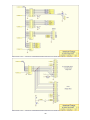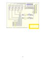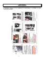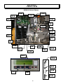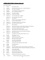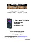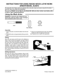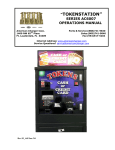
1
American
Changer
1400 NW 65TH Place ♦ Ft. Lauderdale, FL 33309
“PAYSTATION”
OPERATIONS MANUAL
MODELS AC8000/8001/8001.1
CARWASH PAY STATIONS
ARL Listed STD: UL 756
Parts & Service: (888)741-9840
Service Fax: (954)917-5204
Sales: (800)741-9840
To order parts only, visit our website: www.americanchanger.com
Service Questions? E-mail:
[email protected]
Revised October 2009
Model Number:
________________________
Serial Number:
________________________
Tested By:
________________________
Date:
________________________
2
Specifications
Operating voltage
120VAC +10% to -15%
Power consumption
Controller: 100W
Operating temperature
0-120 degrees Fahrenheit
Interface to hoppers
24VDC, 2.5 amps max.
Interface to validators
120VAC, 1.5 amps max.
Hopper coin capacities
100/hopper minimum to 1,600/hopper maximum
(3,200 total maximum)
Warranty Information
A Return Material Authorization number (RMA #) must be obtained before returning
a unit for repair. A copy of invoices must accompany any and all warranty work.
It is the end users’ responsibility to follow cleaning and maintenance procedures as
outlined in the validator manual.
Any unit returned for repair requiring only a cleaning will be charged a flat rate plus
shipping and handling.
Validators
Validators are warranted for two years from date of purchase.
Hopper(s) and/or Dispenser(s) and Logic Board
These items are warranted for one year from date of purchase.
COVERED
•
Manufacturers’ defects in workmanship or materials
NOT COVERED
•
•
•
•
•
•
Damage caused by shipping or physical abuse
Misapplication
Vandalism
End users’ attempt, on their own, to repair components
Cleaning and maintenance
Power surges and lightning strikes
3
Table of Contents
SECTION A: SETUP & INSTALLATION
Setup
............................................
Mounting Instructions
.................................
Power Supply/Relay Board
Fuse Definitions
Main Logic Board
5
5-6
..............................
7
......................................
7
.....................................
8
Hopper Coin/Token Sizes & General Information
...............
9
Validator General Information . . . . . . . . . . . . . . . . . . . . . . . . . . . . .
9
Wire Hookups for the PayStation
..........................
10
Programming the Changer . . . . . . . . . . . . . . . . . . . . . . . . . . . . . . .
11-24
Remote Paging Features & Error Codes . . . . . . . . . . . . . . . . . . . . . . .
25
AC8000/8001/8001.1 PayStation On-Screen Error Indicators . . . . . . .
26
Data Logger Information . . . . . . . . . . . . . . . . . . . . . . . . . . . . . . . . .
27
Replacing Printer Paper
.................................
28-29
Functional Description of the AC8000/8001/8001.1 PayStation . . . . . .
30
Functional Operation of the Hopper Out-of-Service Conditions
......
30
Model X-10 – Coin Learn & Field Test Procedure . . . . . . . . . . . . . . . .
31-32
Car Wash PayStation Schematics
..........................
33-36
PayStation Relay & Power Supply Board Schematics . . . . . . . . . . . . .
37-38
SECTION B: MAINTENANCE
American Changer Cleaning Kit Information . . . . . . . . . . . . . . . . . . . .
39
SECTION C: PARTS LISTS
AC8000/8001/8001.1 Parts Lists . . . . . . . . . . . . . . . . . . . . . . . . . . .
40-42
SECTION D: RELAY LOGIC BOARD & CONNECTIONS
Relay Logic Board Version Rev. “D” and Up (Draft) . . . . . . . . . . . . . .
43
Relay Board Connections
44
........................ .......
4
SECTION A
SETUP & INSTALLATION
Setup
Remove your Series AC8000/8001/8001.1 PayStation from the shipping box. Take the Hex handle out of the
envelope to open the door. (The lock system is a screw-in type and therefore, must be turned at least 10 times
counter-clockwise until it opens.) Inspect for any connectors or components that may have been dislodged during
shipping. The lock and keys for your PayStation will be inside the manila envelope along with this manual. To
install the lock, insert each cylinder into the center of the round holes. Turn the key counter-clockwise ¼ turn and
remove the keys.
NOTE: The only way to get a duplicate set of keys made is to save the tag that
comes between the keys. This ID # starts with “AC or ACC ####.”
CELLULAR WIRELESS CREDIT CARD SYSTEM (optional)
This feature is an optional add-on for most American Changer models.
A separate maintenance manual is
included in your packet. You MUST call American Changer technical support at (888) 741-9840 for setup and
operating instructions. Prior to startup in the wireless mode, the machine will operate and validate cash
transactions only.
TEST:
Before permanently installing the PayStation, do a functional test to verify that there is no shipping damage to
your new PayStation(s).
Connect power through the a conduit into the PayStation. Fill the hoppers with a minimum of 100 coins each to a
maximum of 1,600 coins each (3,200 coins total). On the Power Supply / Relay logic board turn the switch on the
bottom left corner “ON". (See Figure 1.) The rocker switch has a “1” and “0” printed on it. When the “1” is
pressed “IN” the PayStation is “ON”. Make sure the LCD display lights up, the green LED on the top left of the
power supply board comes ON. If this happen occurs, you may continue hooking up the other car wash relay
wiring.
Mounting the AC8000/8001/8001.1
On the bottom of the cabinet of the AC8000/8001/8001.1, locate the 4 mounting holes predrilled into the bottom
of the unit. The other 4 holes are for water drainage. Using lag bolts, bolt down the machine to prevent the
machine from being moved, shaken or tipped over.
REFUSAL TO MOUNT THE CHANGER OR NOT USING ALL 4 MOUNTING HOLES MAY BE DANGEROUS!!!
IF YOU ARE UNSURE IN ANY WAY IN PROCEEDING WITH THE FOLLOWING STEPS, PLEASE HIRE A
LICENSED ELECTRICIAN TO MOUNT YOUR PAYSTATION FOR YOU!
1. Disconnect any and all AC power going to the PayStation.
2. Slide the hoppers out of the cabinet.
3. Choose a height to mount the PayStation. Keep in mind that a SUV or a small car needs to be able to see the
display and insert money into the bill validator and/or a card into the card reader. We recommend the bottom
of the machine should be 30” from the ground. CAUTION: THE PAYSTATION WEIGHS 151 POUNDS. DO
NOT EXERT YOURSELF SO THAT YOU MAY CAUSE AN INJURY.
4. Brick the PayStation base to the required height or mount the stainless steel base (an option we offer)
permanently.
Note: There are 4 drain holes on the bottom of the PayStation to help in water drainage. YOU MUST
mount the Paystation off the concrete slab, about 1” to allow for water to drain from out of the cabinet
5
to the ground below. If you are mounting this machine to a base purchased from American Changer,
the holes are already supplied in the base.
5. Let the electrician run the conduit, install the new breaker, wire, and help decide how the wiring will enter the
PayStation (from the back or the bottom). This will affect the mounting location.
6. Brick in the sides of the PayStation.
7. BEFORE DRILLING THE FOUR MARKED HOLES, ENSURE THAT THERE ARE NO ELECTRICAL WIRES,
TELEPHONE LINES, GAS, OR WATER LINES BEHIND THE WALL WHICH, IF DISRUPTED, MAY CAUSE
A LOSS OF LIFE OR PERSONAL INJURY!
8. Locate the four 1/2” holes on the bottom or on the back wall of the PayStation. Using concrete anchor bolts,
drill and bolt the PayStation cabinet to the brick enclosure.
9. Verify that the machine is securely mounted.
10. Bolt a 2” thick cement top to the top of the PayStation. This allows the enclosure to be retrofitted to add the
light kit later if so desired.
11. We highly recommend HIRING a qualified electrician to perform the following:
12. Secure the 3 electrical wires as follows:
A. Connect the AC hot line to Terminal Block 1, Pin #1.
B. Connect the AC neutral line to Terminal Block 1, Pin #5.
C. Connect the safety ground / earth ground TO THE GROUND STUD OF THE CABINET!
13. Refer to the “Wire Hook Ups for the Paystation” section in this manual for the hook ups for the Car Wash
Controller input lines.
14. Call American Changer Service Department at (888) 741-9840 before using changer.
6
Relay
Input
LEDs
Fuse #4
Power
Supply OK
LED
Fuse #3
24VDC
Input
Jumper to
Main Logic
Board
Fuse #1
CAR WASH
OK LED
ON/OFF
SWITCH
Fuse #2
Car Wash
24VDC input
LED
120VAC
Line Input
120VAC for the
24VDC external
Power Supply
120VAC for
the Heater
120VAC for
the Marquee
Wash Relay &
PayStation
Output Lines
Figure 1 – AC8061 Power Supply/Relay Board
Fuse Definitions
Fuse #1 & #2 - High voltage fuses:
These are the primary transformer AC fuses. Use
replacement 2½ amp fuses ONLY!) REPLACING THIS FUSE WITH ANYTHING OTHER
THAN A 2½ AMP “AS” MAY RESULT IN A FIRE OR AN UNSAFE WORKING
CONDITION! (See Figure 2 – Main Logic Board. Any direct short of the transformer will
cause this fuse to blow. Replace
Fuses #3 & #4 - Low voltage fuses:
These are the secondary transformers fuses
(Fuse #3) for the 5 – 28VDC section of the main logic board and hoppers and the validator
24VAC fuse (Fuse #4). Replace this fuse with a 2½ amp fuse only. REPLACING THIS FUSE
WITH ANYTHING OTHER THAN A 2½ AMP MAY RESULT IN A FIRE OR AN UNSAFE
WORKING CONDITION!
7
Figure 2 – AC8060.2 Main Logic Board
Speaker
Connector
Phone Line
Port
Connector
Jumper to
Power
Supply
Board
Time/Date
Battery
Credit Card
Reader
Connector
Coin mech
connector
Volume
Bill acceptor
connector
Display
connector
Door
Switch
connector
+24VDC
Printer
connector
Left hopper
connector
Fan
Connector
Right hopper
connector
8
Keypad
Connector
Printer
connector
Replaceable
EPROM!
Hopper Coin/Token Sizes & General Information
The hopper will automatically adjust to dispense coins/tokens in size from 20-30 mm in diameter and 1.25-3.5 mm
in thickness. There is an option available to dispense smaller coins.
A nickel is approximately 21 mm, a quarter is approximately 25mm, and a dollar coin is approximately
28mm in diameter.
Hopper coin bin
(Dump the coins into this hole;
1600 coin max.)
Coin counting
optic
12-pin
female
connector
(located
in rear of
hopper)
Motor
Figure 6 – Hopper
Validator General Information
A validator user manual is included as part of your information packet. Please use this as your
reference guide to address any questions you may have.
9
Wire Hookups for the PayStation
Once the PayStation is installed, the next step will be running the wires from the Carwash Controller (CWC) to the
PayStation. There are 2 Terminal Blocks (TB) located in the manual package. Hook the 120VAC wires to the 5pin TB1 as follows:
1. Connect 120VAC HOT to Pin #1.
2. Connect Earth GROUND TO CABINET ONLY!
3. Connect 120VAC NEUTRAL to pin #5.
Note: Skip pins #2 - #4.
THE EARTH/SAFETY GROUND MUST BE HOOKED DIRECTLY TO THE CABINET!
The next step is to hook up the relay wash signals, Unitec protocol CWC return, and 24VDC from the CWC to the
second, longer, terminal block.
1.
Connect the + (positive wire) least expensive carwash relay wire to pin #1 and ground to pin #2.
Note: Pins 2-4-6-8-10 Relay Commons are shorted together.
2.
Connect the + for the second highest carwash relay wires to pin #3 and the common to pin #4.
3.
Connect the + for the third priced carwash to pin #5 and common to pin #6.
4.
Connect the highest price carwash + wire to pin #7 and common to pin #8.
Note: Relay #5 is used in the “Full” & “Blinking” protocol modes as a way for the CWC to monitor the PayStation.
This relay “Shorts” when the PayStation is out of service.
MAKE SURE THE CAR WASH CONTROLLER IS SET FOR THE CORRECT PROTOCOL (To match the correct
protocols for your carwash controller, consult the Programming section of this manual.) Connect the + protocol
wire to pin #11 and the common (or -) to pin #12.
5.
The PayStation needs +24VDC or 24VAC from the Carwash Controller in order to operate. The PayStation
monitors these lines to determine if the CWC is powered up or down. Connect the +24VDC line to pin #13
and the –24VDC to pin #14.
This concludes the wire hook up section.
until they “snap.”
Press the terminal blocks into the connectors on the Main Logic Board
10
Programming the PayStation
Table of Contents
Section
Page(s)
Programming Flow Chart
. . . . . . . . . . . . . . . . . . . . 13-17
Accessing the Program Mode
................
18
Functional Description of All Programming Modes . . 19-24
Dump Mode . . . . . . . . . . . . . . . . . . . . . . . . . . . .
19
Setup Mode . . . . . . . . . . . . . . . . . . . . . . . . . . . .
19
CC Func (credit card functions) . . . . . . . . . . . . .
19
Enable Credit Cards
.................
19
AMERICANX . . . . . . . . . . . . . . . . . . . .
19
DISCOVER . . . . . . . . . . . . . . . . . . . . .
19
Failure Reset. . . . . . . . . . . . . . . . . . . . . . . . .
19
Batch Times
......................
19
More Menus . . . . . . . . . . . . . . . . . . . . . . .
19
Batch Limit . . . . . . . . . . . . . . . . . . . . .
19
Transact. Limit . . . . . . . . . . . . . . . . . .
19
Erase all CC Records . . . . . . . . . . . . . .
19
CW-I0 (PayStation Input/Output setup menus) . .
19
Protocols . . . . . . . . . . . . . . . . . . . . . . . . .
19
Washing
......................
19
WakeUp
......................
20
Protocol Type
..................
FULL PROTOCOL
20
..............
20
BLINKING PROTOCOL . . . . . . . . . . .
20
RESET PROTOCOL . . . . . . . . . . . . .
20
BadBlink
...................
20
..................
20
MORE MENUS
Duration Disable
...........
20
.................
20
Prompt Voice Drive-In . . . . . . . .
20
........................
20
OK Test
Stacking
Wash & Location Names & Wash Values
Name Your Wash
...
20
................
20
Program the Location Name
......
Set the Values of Each of 4 Washes
Protocols
20
...
20
........................
20
11
Programming the PayStation
Table of Contents (continued)
Section
TIME
Page(s)
..... ........................
21
Read Clock . . . . . . . . . . . . . . . . . . . . . . . .
21
Set Clock
........................
21
Set Cancel . . . . . . . . . . . . . . . . . . . . . . . .
21
Set Light
21
........................
MORE MENUS (continued Setup Options)
.....
21
Ans. Rings . . . . . . . . . . . . . . . . . . . . . . . .
21
Demo Mode. . . . . . . . . . . . . . . . . . . . . .
21
FREEPLAY (WASHBUCK) & Hopper Coin Type
21
Set Value of LEFT Hopper
..........
21
.........
21
...........
21
Tokens Once? . . . . . . . . . . . . . . . . . . .
21
More Menus
....................
21
....................
21
Set Value of RIGHT Hopper
Set Value of WASHBUCK
Paging
Pin Number
Test Mode
.................
21
Print Receipt? . . . . . . . . . . . . . . . .
21
.............................
22
Relay Test . . . . . . . . . . . . . . . . . . . . . . . . . . .
22
I-0
...............................
22
Inputs . . . . . . . . . . . . . . . . . . . . . . . . . . .
22
Voltages
........................
22
Keypad . . . . . . . . . . . . . . . . . . . . . . . . . .
22
Outputs . . . . . . . . . . . . . . . . . . . . . . . . . .
22
Display Test
........................
22
Printer Test
........................
22
Status of Operations . . . . . . . . . . . . . . . . . . . . . .
22
Audit
. . .. . . . . . . . . . . . . . . . . . . . . . . . . . .
Reset & Print
22
......................
22
........................
22
View
...........................
22
Print
. . .. . . . . . . . . . . . . . . . . . . . . . . .
22
Variables
... ........................
22
Not Used
Print All CC Records
Print Info
....................
22
... ........................
22
Audit Print Definitions
... ..................
Machine Information Print Definitions
..........
12
23
24
PROGRAMMING FLOW CHART FOR THE PAYSTATION 1F-D04 SOFTWARE
13
14
15
16
17
Accessing the Program Mode
Using the LCD display on the front of the machine programs the PayStation. The “Program” mode must be
entered in order to set car wash pricing, error time outs, audit features using the printer, troubleshooting
features, and dumping the hoppers.
The first thing that must be done to enter the program mode is to enter the “Pin Number.” To do this, you must
OPEN THE DOOR TO THE PAYSTATION! The door switch must be actuated in order to allow the Pin # screen to
be accessed.
1.
Open the PayStation door to at least a 45-degree angle.
2.
Press right two car wash price select keys simultaneously.
3.
Enter the default numbers 4-3-2-1.
Changing the 4-digit pin number.
4.
You may wish to have another pin # besides the default. To change the Pin #, press the following numbers
on the front screen:
A. #2 – Set Up
B. #4 - More Menus
C. #4 - More Menus
D. #2 – Pin #
Default Pin #
is 4-3-2-1.
Press these 2
select buttons
simultaneously
to bring up pin
# screen
Enter the new Pin # and press “Enter”; then repeat a second time to activate it.
WARNING – Once the Pin # IS CHANGED, American PayStation cannot restore the old Pin # without
doing a “System Reset.” A “System Reset” will cause a loss of ALL SAVED AUDIT AND PRICING
DATA!
18
Functional Description of All Programming Modes
Programming will be described as it appears on the screen from left to right starting with the opening menu. ”#”
plus a number (I.e. #2-#2-#3) show which buttons to press STARTING WITH THE MAIN SCREEN that will
navigate you to this step. (*** means that American Changer also downloads this data once the credit card
functions are approved by a processor.)
#1 – The Dump Mode
This mode will cause the hopper(s) to run continuously. While running the front display will show the amount
counted out of each hopper and a total dispensed for audit purposes. Press the “Stop” arrow to end the dump
mode. The dump mode does not show up on the count for the printer audit features for the end of the
week totals.
To get a total of the coins dumped, press the “Print” key before exiting this mode.
#2 – The Set-Up Mode
This mode is quite involved and will be broken down by modes and sub modes.
#2-#1 – CC FUNC (Credit Card Functions)
#2-#1-#1- ENABLE CREDIT CARDS
#2-#1-#1-#1 – AMERICANX (Accept American Express) “YES” or “NO”? Default is “NO.” To change, press the
“YES” or “NO” key on the number pad. ***
#2-#1-#1-#2 – DISCOVER (Accept Discover) “YES” or “NO”? Default is “NO.” To change, press the “YES” or
“NO” key on the number pad. ***
#2-#1-#2 – Failure Reset. NEVER PRESS THIS BUTTON UNLESS A TECHNICIAN AT American Changer
AUTHORIZES YOU TO DO SO!!!
#2-#1-#3 – Batch Times. This is the time in “once a day batching” the modem will call out and transfer the
credit card transactions to the processor. Time is set on a 24-hour clock in hours (hh) and minutes (mm). ***
#2-#1-#4 - More Menus – Credit card options are continued.
#2-#1-#4-#1 – Batch Limit – Highest dollar amount allowed before batch time where modem connects and
downloads Credit Card charges. Default is $899. ***
#2-#1-#4-#2 – Transact. Limit – Limits credit card transactions per card to two per day (midnight to midnight).
“YES” or “NO” Default is “YES.” To change, press the “YES” or “NO” key on the number pad. ***
#2-#1-#4-#3 – Erase all CC Records Erase credit card records in memory that have been authorized, but not yet
downloaded.
WARNING – PRESSING “YES” DELETES ALL CHARGES NOT DOWNLOADED! NEVER PRESS THIS KEY
WITHOUT PRINTING OUT CREDIT CARD CHARGES IN MENU #4-#3!
(End Credit Card Functions)
#2-#2 – CW-IO (PayStation Input / Output set-up menus)
#2-#2-#1 - Protocols The PayStation has 3 CWC values that must be set in order for the machine to function
correctly.
#2-#2-#1-#1 - Washing – This value is the longest that a wash cycle will run. If the CWC’s “Busy” signal lasts
longer than this time interval, the PayStation will place itself out of order. The formula for the “Washing” value is
wash time = minutes X 60 X10; i.e., say the longest wash your carwash has is 4 min. 30 sec. You wish the
timeout to occur at 5 min. Therefore, 5 min = 5 X 60 X 10 = 3000. The Default value is “0000” or to
ignore this feature. ***
19
#2-#2-#1-#2 - WakeUp – This value is the longest time the PayStation will wait for the CWC to respond to a
wash vend signal before going out of order. Formula: WakeUp time = seconds X 10; i.e., if you want the
PayStation to wait 3 seconds before going out of order, then 3 X 10 = 30. The Default value is “0000” or to
ignore this feature. ***
#2-#2-#1-#3 – Protocol Type – Depending on the type of CWC system being used with the Paystation will
determine the type of protocol to use. Examples of the major manufacturers are listed with each protocol to help
set and make your set up smooth.
#2-#2-#1-#3-#1- FULL PROTOCOL – The communication type uses the 24VDC “OK” line on wires #13 & #14 to
check the status of CWC. Car Wash manufacturers using this protocol are: D&S 5000, So. Pride WindTracker,
etc.
#2-#2-#1-#3-#2- BLINKING PROTOCOL – The communication type uses the 24VDC “BUSY” line on wires #11 &
#12 to monitor the status of CWC. It is important to set the “Bad Blink” setting in order for this protocol to
function correctly. Car Wash manufacturers using this protocol are:
#2-#2-#1-#3-#3- RESET PROTOCOL – The communication type uses a special add on logic relay board (ACC
part # AC8062.2-HM) to reverse the input logic coming in from the CWC. The Paystation also uses Relay #5 to
route it’s own 24VDC to trick itself into its own “Busy” signal. Car Wash manufacturers using this protocol ar
Hamilton Conversions and (Some) Southern Prides
#2-#2-#1-#3-#4- BadBlink – This time is the minimum time the car wash can be busy. Any 24V signal on the
busy line less than the time set will be registered as a out of service condition from the CWC. All times are set to
1/10th of a second. I.e. “0020” = 20/10ths of a second or 2 seconds. The Default value is “0000” or to
ignore this feature. ***
#2-#2-#1-#4- MORE MENUS
#2-#2-#1-#3-#4-#1- Duration Disable – Used in conjunction with Cancel button disable. If a PayStation is
disabled due to a timeout of a car NOT driving in to start a wash this timer will reset the machine after either 15,
30 or 60 minutes has expired. The owner also has the option to never allow the machine to come back on with
out a hard reset. The Default value is “NEVER” or a switch reset. ***
#2-#2-#1-#3-#4-#2– OK Test – If the distributor needs to test the unit before it is installed with the car wash
controller. “Enable car wash OK Test?” “YES” or “NO” “YES” turns on the test and the PayStation. This should be
used as a temporary measure ONLY! The Default setting is “NO.” ***
#2-#2-#1-#3-#4-#3- Prompt Voice Drive-in – This allow the owner to choose between telling the customer via
voice prompt to drive in when the transaction is completed or just say “Thank You.”
#2-#2 -#2 – Stacking – Enable stacking of the car wash? (When the car wash is in use, this enables you to take
the next customer’s payment before the first car is finished washing?) “YES” or “NO” Default is “YES.” To
change, press the “YES” or “NO” key on the number pad. ***
#2-#2-#3 – Wash & Location Names + Wash Values
settings.
– Programming the individual wash and location
#2-#2-#3-#1- (#1, #2, #3, #4) – Name your wash using NINE Letters. Once the Alphabet appears use arrow
numbers #2-#3 to navigate the letter choices. #4 arrow enters the character and the #1 erases the last letter
chosen. Note: In order to center the name above each price use the “space” key to center around the nine
spaces. The “space” letter is to the left of the capital “A”. ***
#2-#2-#3-#2-#1 – Program the Location Name - Using 40 total characters. Once the Alphabet appears use
arrow numbers #2-#3 to navigate the letter choices. #4 arrow enters the character and the #1 erases the last
letter chosen. Note: In order to center the name above each price, use the “space” key to center around the 40
spaces. The “space” letter is to the left of the capital “A”. ***
#2-#2-#3-#3- (#1, #2, #3, #4) – Set the values of each of four washes. Each wash must be set in quarter
increments; i.e., a $4.00 wash = 16 quarters or “16”. Minimum wash amount is 25 cents or “01”. Maximum
wash value is $24.75 or “99.” The Default value is $10.00, or “40” for all four washes. ***
#2-#2-#4 – Protocols – This controls the enable/disable logic controlling the bill validator and electronic coin
mech. The Defaults are “LOW” for the Bills and “HIGH” for the Coins.
20
(End CW-IO Functions)
#2-#3 – TIME (Set and observe the time of day.)
#2-#3-#1 – Read Clock – This will show you the time of day of the Paystation.
#2-#3-#2 – Set Clock – this will allow you to set the year, month, day, hour, minute, seconds of the Paystation
in format: yr,mm,dd,hr,mn,ss. Use the number keys to the left of the display to enter this information. Press
the “Enter” key when complete and to start the clock with the new time. Time is set in the 24-hour clock
mode or military time! ***
#2-#3-#3 – Set Cancel – Set the time of day that the “CANCEL BUTTON” is disabled. . Set the Start time of day
the button is disabled. Now set the time of day the button will be re-enabled. Default value is time 00:00 to
00:00. This means the button is NOT DISABLED!***
#2-#3-#4 – Set Light – This option is to set the “On” and “Off” time for the optional light up header. Time is set
in the 24-hour clock mode or military time!
(End TIME Functions)
#2-#4 – MORE MENUS – Continued setup options.
#2-#4-#1 – Ans. Rings – Set how many rings on the incoming phone line before the PayStation’s mode picks up.
The Default value is “3.” ONCE THE PAYSTATION IS COMPLETELY PROGRAMMED, WE RECOMMEND “0” TO
PREVENT TELEMARKETERS FROM GRABBING THE PHONE LINE.
#2-#4-#2 – Demo Mode – This is for show room floor displays only! It enables the credit card reader
without a phone line and is equivalent to a FREE VEND mode! The Default value is “NO”!
#2-#4-#3 – FREEPLAY (WASHBUCK) & Hopper Coin Type – This option sets up the type of coins dispensed
from you hoppers, the value of your WASHBUCK, and if you would like to accept multiple IDX tokens (NOT
WASHBUCKS) for a car wash.
#2-#4-#3-#1 – Set value of LEFT hopper. Set what coin you will vend from your left hopper. Choices include;
NONE or No coins in the hopper, Quarters or quarter valued tokens, and $1 coins or $1 valued tokens. Default
value is “$1 COINS.” ***
#2-#4-#3-#2 – Set value of RIGHT hopper. Set what coin you will vend from your left hopper. Choices include;
NONE or No coins in the hopper, Quarters or quarter valued tokens, and $1 coins or $1 valued tokens. Default
value is “QUARTERS.” ***
#2-#4-#3-#3 – Set value of WASHBUCK. (If applicable) Set the value in increments of a quarter. I.e. If you
WASHBUCK will be valued at $1 then set the value at “04” or 4 quarters. Default value is “00.” ***
#2-#4-#3-#4 – Tokens Once? – This allows the owner to accept the SAME VALUE promotional tokens more than
once. (Note: This does NOT mean WASHBUCKS. We cannot accept multiple WASHBUCKS at this time.) Default
value is “YES.” ***
#2-#4-#3-#4 – More Menus. Setup Cont.
#2-#4-#3-#4-#1 – Paging – Enable the Pager function? “YES” or “NO”. American Changer will set up the pager
phone number when the machine is setup for the first time. You can turn the function on or off locally from the
menu. The Default value is “ON.” ***
#2-#4-#3-#4-#2 – Pin Number – Change the Pin Number of the machine from this menu.
WARNING – Once the PIN NUMBER IS CHANGED American Changer cannot restore the old pin #
without doing a “System Reset.” A “System Reset” will cause a loss of ALL SAVED AUDIT AND PRICING
DATA! P.S.: Don’t lose your new number :o.
#2-#4-#3-#4-#3 – Print Receipt? – This gives the owner the ability to ALWAYS print a receipt after a credit card
transaction or ask the customer a Yes/No prompt if he would like one. The default setting is “ALWAYS.”
(End SETUP Functions)
21
#3 – The Test Mode - (PayStation Test Options)
#3-#1 – Relay Test - This function tests the relay board for faulty relays. By putting the PayStation into this test
you can monitor that all relays are “clicking”, as they should. This will also light the LED associated with the
relay. The LED lighting IS NOT an indication that the relay is good. (Relay board Part number AC8061.)
#3-#2 – I-O – This will test the input/outputs present throughout the machine.
#3-#2-#1 –Inputs – These are the inputs. “I” are “shorts” or “on” or “+5-v”. the “0” is “open” or “off” or
“ground”.
#3-#2-#2 – Voltages – These are the machine power supply voltages. They are listed as follows:
V1
V2
V3
V4
=
=
=
=
V5 =
V6 =
V7 =
V8 =
(5-Volts) 4,900-5,150 is good.
(10-Volts) 9,000-11,000 is good.
(Unused)
(24-Volts) Power Supply –
24,000-25,000 is good
(24-Volts) Hoppers –
24,000 – 24,500 is good
(m amps) Left Hopper current 27-50
(m amps) Right Hopper current 27-50
Temp inside cabinet in CELSIUS! (Double it and add 30 to get Fahrenheit.)
Heater comes on at 5-10 C.
#3-#2-#1 –Keypad – Tests all the buttons of the keypad by showing them on the LCD display. Does not include
the “cancel” button. Exiting the test tests this button.
#3-#2-#1 –Outputs – These are the outputs. “I” are “shorts” or “on” or “+5-v”. the “0” is “open” or “off” or
“ground.”
#3-#3 – Display Test – This will illuminate the front display. This test is helpful in discovering any nonfunctioning display lines or a display harness in case of failure.
#3-#4 – Printer Test – This test will verify if the printer is functioning properly. Note: Most printer problems
occur when changing out the paper due to improper feeding of the new paper.
(End TEST Function)
#4 – Status - (PayStation Status of Operations)
#4-#1 – Audit (PayStation Audit Options)
#4-#1-#1 – Reset & Print – This function will print all counters for the PayStation and reset the resettable counts
to zero. It cannot reset the non-resettable counters. The sequential number counter is incremented by one.
#4-#1-#2 – Not Used
#4-#1-#3 – View – Show on the display only basic accounting counters.
#4-#1-#4 – Print – Prints accounting totals without resetting the counters.
#4-#2 – Variables (PayStation display of watchdog parameters.)
#4-#3 – Print all CC Records (Prints all Credit card charges remaining in memory. This are only the
charges not yet downloaded to the bank.)
#4-#4 – Print Info (PayStation print out of all parameters.)
On the AC8000 that does not have the printer, the display will show the basic accounting features. Total
Bills Inserted, Total washes, etc. Please copy down the totals from the front display for your records.
22
Audit Print Definitions
Car Wash ### - Audit
Date – year, mm, dd -Time – hr: mm: ss
Audit Sequence #
#
Machine Number
Year, month, day, time and sequence number
of the report.
Total Money:
$ #####. ##
Non-resettable count of total bills accepted
by the machine in its lifetime.
Total Bills:
$
#####
Total Paper bills accepted - Resettable
Ones:
$
#####
Total $1 bills accepted - Resettable
Fives:
$ #####
Total $5 bills accepted – Resettable
Tens:
$
#####
Total $10 bills accepted – Resettable
Twenties:
$
#####
Total $20 bills accepted – Resettable
Fifties:
$
#####
Total $50 bills accepted – Resettable
Hundreds:
$
#####
Total $100 bills accepted – Resettable
Dollar Coins:
$ #####
Total $1 coins accepted – Resettable
Quarters:
$
#####
Total .25 accepted – Resettable
Tokens:
$
#####
Total IDX Tokens accepted – Resettable
TokenNotes:
$
#####
Total WASHBUCKS accepted - Resettable
CreditCards:
$
##, ###. ##
Total Credit Card sales – Resettable
Change-Hop-1: $
##, ###. ##
Total change out LEFT Hopper – Resettable
Change-Hop-2: $
##, ###. ##
Total change out RIGHT Hopper– Resettable
Washes-1:
####
Total LEFT wash button - Resettable
Washes-2:
####
Total 2ND wash button - Resettable
Washes-3:
####
Total 3RD wash button - Resettable
Washes-4:
####
Total RIGHT wash button - Resettable
Washes-Total:
####
Total ALL Washes – Resettable
Hopper #1:
OK
Status of LEFT Hopper
Hopper #2:
OK
Status of RIGHT Hopper
Validator:
OK
Status of Bill Acceptor
Credit Card:
OK
Status of CREDIT CARD Operations
Total Hop-1:
$
##, ###. ##
Lifetime dispensed LEFT Hopper-Non-Resettable
Total Hop-1:
$
##, ###. ##
Lifetime dispense RIGHT Hopper-Non-Resettable
23
– continued –
Machine ### - Information
Year-mm-dd – Time: hr: mm: ss
Demo Mode =
NO
Is machine in the Demo Mode?
PagerEnabled = y or n
Hopper1 Type =
#
Hopper2 Type =
#
Type of coins dispensed from each hopper.
1=quarter, 4=$1 coin, 0=None
Selection #1 =
$
##. ##
Selection #2 =
$
##. ##
Selection #3 =
$
##. ##
Selection #4 =
$
##. ##
Cost of all 4 washes in dollars.
IDX #1 Value =
##
IDX #2 Value =
##
IDX #3 Value =
##
IDX #4 Value =
##
Value of each IDX Token used. Totals are in quarter
increments.
FreePl. Value =
##
Value of WASHBUCK coupon used. Total is in
quarter increments.
Capture $
=
####
Set how much machine will batch out at in
dollars.
Dollar Now =
####
How much CC sales equal that have not been
batched yet today.
Sched. Capt.
=
hr: mm: ss
Time machine is set to do once a day
batching.
Ring Answer
=
#
How many rings the PayStation modem will
allow before picking up.
Audit Ptr Addr=
XXXX
AuthDoneAddr= XXXX
CaptWorkAddr= XXXX
CaptDoneAddr= XXXX
Bill Validator = Low
Coin Acceptor = Hi
Reset Timer = No
Multiple Token= XX
CW Protocol
XXXX
CW OK Test
XXXXX
Cancel En/Dis
XXXXXX XXXXXX
Time cancel button is turned on until off.
Max Blink Time
.XX Sec
Max Busy Time
.XX Sec
Max WakeupTime .XX Sec
Stacking
Y or N
Is PayStation in the stacking mode.
PhoneAuthPri = ##########
PhoneAuthSec= ##########
PhoneCaptPri = ##########
PhoneCaptSec= ##########
Phone numbers PayStation calls out to Authorize
and Charge Credit Cards.
PhoneOffice = Not Used
PhonePager = ##########
Phone number called when PayStation or Car Wash
Controller is down.
BIN
=
Agent Bank =
Agent Chain =
Merchant # =
Store #
=
Terminal #
=
Merch Categ =
Merch City
=
Merch State =
ZipCode
=
Country Cod =
CurrencyCd =
Merch Loc
=
Terminal V# =
TimeZoneDif =
######
######
######
############
####
####
####
XXXXXXXXXXX
XX
#####
###
###
000001
########
###
Internal use only!
System Data Logger Information
See Data Logger Information in this manual.
– End Machine Info Print Out –
These are your credit card set up functions.
Underlined items may be requested by
technical support when you call in with a cardprocessing problem.
- End of Programming Section –
###
Batch Seq. # =
The current processing batch number.
Max twice CC =
y or n
CC# limit 2 times in 24-hr period?
Accept Am-X =
y or n
Discover
=
y or n
Machine accepts Amex/Discover Cards?
24
PayStation Remote Paging Features and Error Codes
The Paging option pages/calls the owner if the PayStation detects a problem.
For the paging option to work, the PayStation must be configured remotely by American Changer to
load the pager number into the software.
The PayStation will page most numeric pagers. (A cell phone with caller ID can be used, but there is no error
code transmitted. The only thing seen will be that the phone number to which the PayStation is connected called).
If you are using a cell phone and see that the PayStation is calling, refer to the Programming section in this
manual.
Once the telephone number is configured in the PayStation, the paging function is operational. It can be turned on
and off via the setup menu.
While the PayStation is paging, the display momentarily shows:
“Paging Service Center”
The following is a list of the codes that will be sent to the pager:
*00 * ID # of Machine * up to 4 error codes *
The 4 error codes are:
01 Hopper
02 Validator
03 Credit card/phone
04 Car wash
Example: A validator problem would usually display
The first
two digits
come up
zero.
The next three digits
are the machine
numbers chosen by
the user during
configuration.
25
00|333|02
The last two
digits is the
error code with
a zero in front.
AC8000/8001/8001.1 PayStation On-Screen Error Indicators
When the PayStation is functioning with no errors and is configured to accept credit cards, the
main screen appears as below. The “Push Arrows to Select Payment Method” appears for
approximately three seconds, then disappears.
PAYSTATION
PAYSTATION
Push Arrow to Select Payment Method
CREDIT CARD
CASH/TOKEN
CREDIT CARD
CASH/TOKEN
If three asterisks or stars alternately appear with the “Push Arrows to Select Payment
Method,” it is possible that there is an error. These are displayed when running in a onehopper mode. Also, they will appear if a credit card fails to authorize when it is swiped; but
once a successful authorization occurs, they disappear.
To determine if there is an error, perform the following:
PAYSTATION
**
CREDIT CARD
CASH/TOKEN
1. PRESS ARROW TO SELECT CASH/TOKEN.
PAYSTATION
Push Arrow Below to Select Wash Type
$8.00
Super
$7.00
Deluxe
$6.00
Plus
$5.00
Express
2. PRESS ARROW TO SELECT ANY WASH.
**
Please Deposit Money or Cancel
Wash Type Selected:
Super
Deposited: $ 0.00
VALIDATOR | CREDIT CARD
**
More needed $7.00
LEFT HOPPER | RIGHT HOPPER
ERROR CODES ARE INDICATED AS ABOVE ON THE DEPOSIT MONEY SCREEN
26
Data Logger Information
Current defined Codes are:
The printout shows the last 25 events. This data is
shown on the bottom of the Machine “Print Info” print
out.
OK
Bad
Aprv
Rej
GB
QD
NoDT
Busy
Nanr
Phon
Othr
Modm
Comm
Data
Exp
Type
Time
Rept
From left, the data fields are:
DD
HH
MM
= day of the month
= hour in 24 hour format
= minutes
Evnt
Code
= Event occurred
= Result code of event
Flag
Flag
Flag
Flag
Flag
=
=
=
=
=
1
2
3
4
5
Wsh_Flag
CC_Veri
CC_Stat
CC_Fail
Pager
WshFail
CC_Veri
CC_Stat
CC_Fail
PagerFlg
Current defined events are:
=
=
=
=
=
=
=
=
=
=
=
=
=
=
=
=
=
=
OK
Bad
Approved
Rejected
Good Batch
Quit Duplicate
No Dial Tone
Busy
No Answer
Phone Problem
Other problems
Modem Failure
Communication Failure
Bad CC data (read problems)
Expired Card
Wrong type card
Timeout on CC
Too many repeat uses
Note: A brand “X” card might be listed as wrong type
or bad date if the internal fields are different from a
standard credit card.
Strt
= Power up or Restart
Flag
= Flag Failure
Wash = Washer started
Ring
= Ringing
OffH
= Going Offhook (Dialtone ?)
Auth
= CC Authorize
Bat
= Batch
Page
= Page
Swch = Switched to cash
Ccrd
= Credit card read and failed (good ones not
recorded)
Pager Flag: Emergency pager flag
All 0
0
1
2
3
4
5
6
7
27
= No problem = no page
= Counter 0-15 Counts down in minutes time
to page
= Counter
= Counter
= Failed to send page bit
= Hopper Errors
= Validator Errors
= CC Errors or communication
= Equipment failure
Replacing the Printer Paper
Before the printer paper runs out, you might wish to contact your Distributor and order more Printer paper. The
part number is AC7071-01, and it is a special brand which is hard to find. Most AC800/8001/8001.1 problems
occur from the printer. Either the operator buys the wrong paper or has trouble loading the paper. Please follow
the steps of either Method #1 or Method #2 below to properly load your thermal printer with new paper.
Figure P1: AC7074 `Printer – Rear View
Method #1 – Automatic Feed:
NOTE: This method must be performed with the board power ON.
1. If there is paper remaining on the previous roll, it must be removed before proceeding. Move the “Paper Feed
Lever” from the DOWN to the UP position (refer to Figure P2), and then pull out the remaining paper from the
rear of the printer and discard the roll.
Paper Feed
Lever
Figure P2: AC7074 Printer – Side View, with Paper
2. Move the “Paper Feed Lever” back to the DOWN position. Slide a new roll of paper onto the “Roll Holder,”
oriented so the paper comes off on the side toward the printer (refer to Figure P3 for the correct placement).
28
Figure P3: AC7074 Printer – Side View, Showing Proper Roll Placement
3. Wrap the paper under the “Paper Guide” and begin to feed it into the “Paper Slot.” You do not need to fold or
cut the paper in any way; it should be left square in the front. At a certain point as the paper is being fed in,
the printer will detect it and automatically feed it to the printing position. When done, the setup should look
like Figure P3.
4. IMPORTANT! Turn OFF the Main Board power, and turn it ON again after a few seconds. Note: The printer
will not work until the power has been cycled!
5. Enter the Setup Mode and perform a Printer Test. Make sure the printer prints all of the lines of text and cuts
off the paper.
Method #2 – Manual Feed:
NOTE: This method can be performed with the board power ON or OFF.
1. If there is paper remaining on the previous roll, it must be removed before proceeding. Move the “Paper Feed
Lever” from the DOWN to the UP position (refer to Figure P2), and then pull out the remaining paper from the
rear of the printer and discard the roll.
2. With the “Paper Feed Lever” still in the UP position, slide a new roll of paper onto the “Roll Holder”, oriented so
the paper comes off on the side toward the printer (refer to Figure P3 for the correct placement).
3. Wrap the paper under the “Paper Guide,” and begin to feed it into the “Paper Slot.” You do not need to fold or
cut the paper in any way; it should be left square in the front. Continue to feed the paper into the slot, through
the print head, until it passes out through the front of the machine (refer to
Figure P4).
4. Move the “Paper Feed Lever” back to the DOWN position. The printer is now ready to print.
5. Enter the Setup Mode and perform a Printer Test. Make sure the printer prints all of the lines of text and cuts
off the paper.
Figure P4: AC7074 Printer – Front View, Paper Fed Through
29
Functional Description of the AC8000/8001/8001.1 PayStation
After the PayStation has been installed and the computer programming is completed, the machine is ready to
operate. Exiting the “Program” mode will bring up the main Pricing screen. A voice will prompt you to select a car
wash type.
Using the select buttons, choose a car wash. YOU MUST SELECT A CAR WASH TYPE BEFORE THE PAYSTATION
WILL ACCEPT ANY TYPE OF CURRENCY!
Once the pricing type is selected, a voice prompt will ask the customer to deposit the money. The only pay types
are bills, $1 coins, quarters, or IDX tokens. Insert one of these payment types at this time.
Once the amount of the car wash selected is reached, the PayStation will send a wash pulse to the CWC. As the
wash relay is pulled, the green LED on the Power Supply/Relay Board will flash, showing the pulse sent to the
CWC. If the CWC is busy washing another car, the PayStation will wait until the busy signal from the CWC drops to
0V. At this time, a multiple of things occur:
1.
The bills inserted count up the “Total Money” and all other associated audit features.
2.
The wash total electronic counter is incremented by 1.
3.
If there is any change to be given back, a correct mixture of $1 coins and quarters will be received by the
customer. These audit counters are also incremented.
4.
If the customer presses the “cancel” button on the keypad, a refund in $1 coin and quarters is given back to
the customer. The coins and bills will increment on the audit counters.
Functional Operation of the Hopper Out-of-Service Conditions
In a two-hopper system, the other hopper will work as a backup or give change as needed.
system there is no backup.
In a one-hopper
There are 4 instances that will shut down a hopper:
1.
Low Coin Error – This is the most common occurrence. This shutdown occurs when the coins in the hopper
fall below the gold plates, which conduct low voltage between them. The hopper will dispense coins from the
other hopper when the PayStation reads the signal. Once the first hopper is read to have “low coins,” a call
over the phone line is place to the pager/cellphone that one hopper is down. If the other hopper runs out of
coins THE PAYSTATION WILL CONTINUE TO DISPENSE COINS FROM EITHER HOPPER UNTIL BOTH HOPPERS
TIME-OUT WITH A JAM ERROR CODE. AFTER BOTH HOPPERS ARE EMPTY, THE PAYSTATION WILL
CONTINUE TO OPERATE. THE MACHINE WILL NOT SHUT DOWN IF BOTH HOPPERS CANNOT
DISPENSE COINS! A second call on the pager will now be placed, telling the operator that the second
hopper is “Low.”
2.
Security Error – There are two cases that will cause a security error:
3.
a.
The hopper is missing. The hopper is not slid into the hopper plate connector.
b.
There is a foreign object or coin lodged in the coin counting window. Remove the side of the
hopper with five screws, and look in the area where the coins exit the hopper. Check the slot
for foreign matter, and remove it from the slot.
Jammed or Time-out Error – This error occurs when the hopper is told to dispense coins and, after 45
seconds, no coin has been dispensed. This error exists when the hopper coin belt is jammed or the hopper
has run out of coins. If the coin belt is jammed, refer to your hopper manual for instructions to un-jam the
hopper.
4. Over-Pay Error – This is the error that occurs when the hopper pays out more coins than told to dispense. A
very dirty exit sensor most often causes this error.
30
Model X10 Coin Learn & Field Test Procedure
IDX INC
Coin Learn Procedure
1. Slide the front cover up, and identify the three controls to be used in this procedure:
•
Black or Red push-button near center bottom (used to input the number of credit pulses)
•
16-position rotary switch to the right of the push-button (#0 is normal RUN position; #1-#6 are for
learning each of 6 possible coin types that can be accepted). (#0 is normal RUN position; #1-#9 and #A,
#B, #C are for learning each of 12 possible coin types that can be accepted)
•
LED indicator half-way up on the right side (green in RUN mode, red in LEARN mode)
2. Turn the rotary switch to one of the LEARN positions #1-#6 or #1-#C (for example, pick #3 for learning the
3rd coin type), and observe the LED turns red to indicate it is now ready to learn.
3. Push the black or red button once for each credit pulse you wish to have issued for this coin. For example, a $1
coin would require 4 credit pulses if you are also accepting $0.25 coins for one credit pulse.
4. Slide the cover back on the unit to make sure outside light does not interfere with the sensors.
5. Show the unit 6 different samples of the coin by depositing them into the acceptor as usual. It is best to use 6
different coins, since there are typically slight variations from coin to coin.
6
After the 6th sample coin is deposited, the LED will flash red-green a few times to indicate the LEARN
procedure is complete and the coin parameters are stored in memory.
7. Slide the front cover open again, turn the rotary switch back to position #0, and observe the LED turning
green. Check that you have not accidentally turned it too far to position #15, which is a field test function
position in which it will not accept coins.
8. Slide the front cover back down and you should now be able to accept the new coin.
Coin De-Learn Procedure
1. Slide the front cover up, and turn the rotary switch to the coin # position you wish to DE-LEARN.
2. Push the black or red button once to initiate the LEARN sequence.
3. Turn the rotary switch back to position #0 without depositing any coins to signal the unit that you wish it to
erase the parameters for this coin. The LED will flash red-green to indicate completion.
4. Slide the front cover back down.
FIELD CASE & DIAGNOSTICS
A green LED shows normal operation in switch position #0. If the LED is flashing yellow or alternately red-green, it
indicates a malfunction has been detected. Some malfunctions can be corrected in the field. See below.
GATE RELAY TEST (rotary switch #0)
Press the black or red button to activate the gate relay. If not normal, it may be physically obstructed or its wire
unplugged.
INDUCTIVE METAL SENSOR TESTS (rotary switch #E, #F)
Turn the rotary switch to positions #E and #F to test the inductive sensor. Normal LED color is green. A red color
indicates that either there is metal in front of the inductive sensors or the circuit is malfunctioning.
DIAMETER OPTICS SENSOR TESTS (rotary switch #B, #C, #D)
Turn the rotary switch to positions #B, #C, and #D to test the diameter thru-beam optical sensors. Normal LED
color is green. A red or orange color indicates that either there is an object or dirt blocking one of these three
sensors and cleaning of the coin cute is required, or that the circuit is malfunctioning.
31
X-MARK CODE OPTICS SENSOR CALIBRATION (rotary switch #9)
Fold a piece of white paper twice (to 4- thickness), and insert it into the center of the coin chute. Turn the rotary
switch to position #9 (front side optics) and press the black or red button. The unit will use information gathered to
calibrate the sensitivity of its reflective sensors for reading the X-Mark optical code on tokens. The LED should be
an orange color after calibration. Repeat for switch position #A (rear side optics).
CREDIT SENSOR TEST (rotary switch #8)
Turn the rotary switch to position #8 to test the Credit Sensors (V2.0 chip and after). If not installed, the LED will
blink yellow; if installed and in good order, it will be green; if installed and dirty or blocked, it will be an orange to
red color.
MEMORY TEST (rotary switch #7)
Turn the rotary switch to positions #7 to test the validity of memory. Normal LED color is green. A red color
indicates that memory is corrupted. It may be possible to correct this by re-learning the coins. If not, the
memory chip is bad.
32
Car Wash PayStation Schematics
33
34
35
36
PayStation Relay & Power Supply Board Schematics
37
38
SECTION B
MAINTENANCE
A full-size version of the cleaning kit instructions is included in your
information packet.
39
SECTION C
PARTS LISTS
AC8001 Cabinet Shown
#18
#24
#22
#19
#1
#20
#9
#13
#16
#2
#17
#10
#11
#3
#7
#6A
#8
#30
#31
#6
#25
#14
#23
#26
#27
#28
#4
#5
#29
40
AC8000/8001/8001.1 Cabinet Parts List
S/S = Stainless Steel
#1
AC8010
S/S Cabinet w/Door
#2
AC8010.1
S/S Door ONLY (No Lock Assy. or LEXAN Door Sticker)
#3
AC8010-01
S/S Coin Cup Complete
#4
AC8065
S/S LCD Display Assembly Complete!
#5
AC8065-03
Clear Lexan Display Protector
#6
AC8010-04
S/S Hopper Platform
#6A
AC8060-HTR
Heater for the AC8001
#7
AC8010-05
S/S Lock Bracket Assy. Complete
AC8010-05A
S/S Lock Bracket Frame ONLY!
8010-33
S/S Cage Nut
8010-35
Welded T-Nut Cage Holder w/Nylock Bolt
#8
7071-01
4” Printer Paper Roll ONLY!
#9
AC8010-071
S/S Waterproof Speaker Box W/Speaker
#10
AC8010-01A
S/S Coin Cup Funnel (1 piece)
#11
8900
Manual AC8001
AC8010-09
(Not Shown) S/S Left Conduit Double Hole Block (for Hamilton’s)
AC8010-10
(Not Shown) S/S Right Conduit Double Hole Block
AC8010-11
(Not Shown) S/S Outside Fan Cover
AC8010-12
S/S IDX Electronic Coin Mech Bracket Complete
AC8010-13
(Not Shown) S/S Condor Coin Mech Bracket Complete
AC8010-14
Black Metal Coin Box
AC1047-H
(Not Shown) ACC Hopper Plate w/Harness (1 of 2)
#16
AC1047
ACC Hopper (1 of 2)
#17
AC2066.5
IDX Electronic coin Mech
AC2066.3
(Not Shown) Electronic Coin Mech
AC8060.4
Main Logic (Control) Board
AC8067
(Not Shown) Modem Board
AC8061
Power Supply Relay Board
AC8062
(Not Shown) 24VDC Switching Power Supply
#20
AC9090
Credit Card Reader
#22
AC8064
Fan 12VDC
#23
AC8065-01
Deep S/S Display Protector (Requires Display Lexan Protector)
AC8065-02
Shallow S/S Display Protector (Requires NO Display Lexan Protector)
#24
AC9022
Pyramid Bill Validator
#25
AC8080
Lock Assembly Complete
#26
AC1092
Medeco Inserting Lock & Keys
#27
8080-01
S/S Outside Ring Medeco Collar
#28
8080-02
Aluminum Hex Bolt Holder w/ Set Screw
#13
#14
#18
#19
#29
8080-03
Hex Bolt Assembly (With spring & clips & washer)
41
8080-04
Hex Bolt Lock Crank (Not Shown)
#30
AC7074
Audit Printer for the AC8000/8001 Complete
#31
AC9081
Lexan Front Overlay for the AC8000
Wire Harnesses for the AC8000 PayStation
AC7084-H
Printer Power Harness
AC7071-RH
Printer RIBBON Cable Harness
AC8060-DSH
Door Switch to MLB Harness
AC8060-H
24VSA Validator Wire Harness
AC8061-RH
Relay / PS Board to MLB RIBBON Harness (3”)
AC8065-RH
LCD Display RIBBON Harness
AC8066-H
KeyPad to MLB Harness
AC8066.5-H
IDX Coin Mech Harness
AC9090-RH
Credit Card Reader RIBBON Harness
42
SECTION D
RELAY LOGIC BOARD & CONNECTIONS
43
RELAY BOARD CONNECTIONS
44