1
WARWICK WIRELESS
LIMITED
X7220 DUAL REDUNDANT BASE STATION
WARWICK WIRELESS LIMITED
THE MANOR, ASTON FLAMVILLE, LEICESTERSHIRE, LE10 3AQ ENGLAND
TEL: +44 (0) 1455 233616 FAX: +44 (0) 1455 233179 WEB: www.radiotelemetry.co.uk
INDEX
1.0
FEATURES
2.0
SPECIFICATION
3.0
INTERFACES
3.1
Communications Port 9 Way D Connector
3.2
Service Port 9 Way D Connector
3.3
LED Indicators
3.4
Fuses
3.5
Program Switch
3.6
Alarm Reset Switch
3.7
Antenna Connectors
3.8
Power supplies
4.0
OPERATION
5.0
GETTING STARTED
5.1
Basic Connections
5.2
Power Connections
5.3
Plug and Play
6.0
CONFIGURATION
6.1
Communication Port Menu
6.2
Service Port Menu
7.0
RADIO TRANSMISSION
7.1
Radio Frequency
7.3
Radio Propagation
7.4
Antennas
8.0
TROUBLE SHOOTING
8.1
No Data Transmission
8.2
No Data Reception
8.3
Corrupt Data
8.4
Radio Path
8.5
Help Line Number
9.0
WARNING
1.0 FEATURES
•
Operates on international licensed and licence free radio bands.
•
RF Bands:
•
Conforms to ETSI 300-220, ETSI 300-113, ETSI 300-683, MPT1329.
•
Two Independently X7200HP Radio Modems in hot standby.
•
17 selectable radio channels.
•
RF Power 1W and 5W
•
RS232/RS485 serial Interface with baud rates of 1,200 to 38,400.
•
Service and monitoring RS232/RS485 serial port.
•
Remote monitoring and configuration of outstation modems.
•
Addressable individually and globally.
•
On-line AT commands for network control.
•
Variable Data Packets and error checking mode.
•
1U, 19 inch rack mounted enclosure.
147MHz to 174MHz VHF
400MHz to 500MHz UHF
868MHz to 920MHz UHF
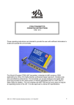
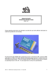
The X7220-2 Dual Redundant Base Station consists of two X7200 Radio Modems, two power supplies and an
independent monitoring system. Only one Radio Modem is operational at any time with the other in hot standby. If
any of the monitored parameters such as bit error rate, RF Power, RF sensitivity, Power Supply should exceed
there pre-set limits then the second X7200 will be brought into service and the fault reported via the monitoring
serial port and a relay contact closing. The in service radio modem will be changed automatically after a pre-set
duty time.
A 4K buffer memory is provided on each radio modem so that data can be passed asynchronously between the
host and modem without the need for handshaking. The CTS output signal on the communication port can be used
for flow control in duplex applications. The over air data speed can be configured at either 5K bits/sec or 10K
bits/sec. This is independent of the baud rate and should be set to a lower value where possible for the best radio
propagation.
The set up menu of the X7220-2 can be accessed either by a PC running any terminal emulation program like
Hyperterminal in the Accessories Section or remotely over the radio link. The set up menu is selected from the
serial serves and monitoring port. The menu configuration is permanently stored on EEPROM.
On-line “AT” commands can be sent to the modem to change the address configuration or RF frequency during
normal operation so that any modem can “dial up” any other modem on the network. The repeater path can also be
altered.
The X7220-2 Dual Redundant Base Station is housed in a 19 inch rack and can be powered from 240V power
source.
2.0 SPECIFICATION
ABSOLUTE MAXIMUM RATINGS
Storage Temperature ......................................... -30 to +85 Celsius
Operating Temperature ...................................... -10 to +55 Celsius
DIMENSIONS X7220HP UHF 1- 5W ................ 1U 19 Inch rack
ELECTRICAL CHARACTERISTICS
Frequency Range
Channels
Channel Separation
Start up Time
Modulation
Power Supply
MIN
458.500
400.000
147.000
12.5
5.0
12
TYPICAL
17
25.0
10.0
F3D, F1D
24
MAX
458.950
480.000
174.000
DIMENSION
MHz
MHz
MHz
NOTE
UK
World
Si
25.0
30.0
KHz
mSecs
With $ Selected
30
Vdc
110V, 240Vac
5
10
5
W
V
V
KHz
Kbps
TRANSMITTER
RF Power X7220HP
Data Input RS232
Data Input RS485
Frequency Deviation
Modulation Rate
Supply Current
1
-10
0
+/- 3.0
DC
0.89
RECEIVER
IF Frequencies
Sensitivity
Bandwidth
Data Output RS232
Data Output RS485
Carrier Detect
Supply Current
Supply Current Standby
+/- 7.5
-10
0
-10
80
0.005
10.0
3.1
3.2
45/455
0.9
KHz
90
0.007
Amps
MHz
µV
10
5
10
105
0.01
25KHz Channel
V
V
V
mA
mA
3.0 INTERFACES
3.1 Communication Port 9 Way D Type Connector RS232/RS485
1
6
2
7
3
8
4
9
5
PIN 1 AL1
PIN 2 RD
PIN 3 TD
PIN 4 NU
PIN 5 OV
PIN 6 AL2
PIN 7 –VE
PIN 8 CTS
PIN 9 +VE
ALARM CONTACT
ALARM CONTACT
RS232 RD RECEIVE DATA
-VE RS485
RS232 TD TRANSMIT DATA
CTSI
NU
+VE RS485
0V
OUTPUT
OUTPUT
INPUT
INPUT/OUTPUT
OUTPUT
OUTPUT
INPUT/OUTPUT
INPUT
Voltage free, normally open contact
RS232 Receive serial data from host
RS232 Transmit serial data to host.
Not Used
0V common for host.
Voltage free, normally open contact
RS485 Bi-directional data.
Brought low by the modem when a RF carrier is detected or the receiver buffer memory is full.
This can be connected to RTS on the host to inhibit data from the host in duplex operations.
RS485 Bi-directional data.
3.2 Service Port 9 Way D Type Connector RS232/RS485
1
6
2
7
3
8
4
9
5
PIN 1 NU
PIN 2 RD
PIN 3 TD
PIN 4 NU
PIN 5 OV
PIN 6 CON
PIN 7 –VE
PIN 8 NU
PIN 9 +VE
NOT USED
CONFIGURATION MODE
RS232 RD RECEIVE DATA
-VE RS485
RS232 TD TRANSMIT DATA
NOT USED
NU
+VE RS485
0V
INPUT
INPUT
INPUT/OUTPUT
OUTPUT
INPUT/OUTPUT
INPUT
Not Used
RS232 Receive serial data from host
RS232 Transmit serial data to host.
Not Used
0V common for host.
Configuration input. Connecting 0V to this input will send the configuration menu to the host
when the power is applied. It is left open circuit for normal operation.
RS485 Bi-directional data.
Not Used.
RS485 Bi-directional data.
3.3 LED Indicators
Eight LED’s on the front of the modem indicate the following states:
Transmit Data 1
Receive Data1
PSU 1
Fail 1
Green
Green
Red
Red
On when modem 1 is transmitting data.
On when a RF carrier of greater than 0.9uV is detected
On when Modem 1 power supply is good.
On when a fault is detected in Modem 1
Data 2
Receive Data 2
PSU 2
Fail 2
Green
Green
Red
Red
On when modem 2 is transmitting data.
On when a RF carrier of greater than 0.9uV is detected
On when Modem 2 power supply is good.
On when a fault is detected in Modem 2
3.4 Fuses
Fuse 1
Fuse 2
1 Amp Fuse for modem 1 PSU
1 Amp Fuse for modem 1 PSU
3.5 Program Switch
Three way switch for changing the parameters of both modem 1 and modem 2.
Central
Right
Left
Run
Program modem 1
Program modem 2
3.6 Alarm Reset
Resets alarm states
3.7 Antenna Connections
Two 50 ohm, N-Type Sockets.
Antenna 1
Antenna 2
Socket for Antenna 1
Socket for Antenna 2
3.8 Power Supply
Three pin plug for 240V mains power supply is
4.0 OPERATION
When power is applied to the Dual Redundant Base Station all the monitored parameters are checked along
with the LED’s. If no faults are found modem 1 is enabled. The Duty Cycle Timer is enabled and this then cycles
the two modems according to the time set in the service menu. ( 1 to 48 Hours)
If a fault is detected in the operational modem then the Fault LED will light, the Fault Relay will energise, an
error code will be set in the service menu and the alternative modem will be selected.
A transmission is started by sending data to RD (pin 2) on the serial communication port. The operational radio
modem places this data in the transmitter buffer memory while it checks to see if the RF. channel is free. If it is
not then the data is stored in the buffer until the channel becomes free. If it is free then a preamble message will
be transmitted so that the receiving modems can align to the incoming data.
The modem will then transmit a repeater command byte, if set, and a transmitter address byte followed by the
data that has been placed in the buffer memory. The transmission is terminated when a gap of two data bytes is
detected in the incoming data stream.
If more data is sent after a gap of two data bytes then the above sequence will be repeated.
When the receiving modem detects the presence of incoming data it takes CTS (pin 8) low. The repeater
command byte is decoded and the transmitter address compared to the receiver address. If they are the same
or if the global address of 00 is decoded or if the address mode is switched off then the data will be presented at
the serial output port TD (pin 3). At the end of the message CTS is taken high.
If the repeater command is decoded or the repeater mode set in the configuration menu then the data will be
stored and then re-transmitted.
The best results are obtained from the radio modem by setting the transmission speed to the slow setting and
the baud rate to either 4800 or 9600.
5.0
GETTING STARTED
5.1
Basic Connection on the communication and service ports
TRANSMIT
RECEIVE
GROUND
5.2
(TD)
(RD)
(0V)
ON HOST TO RECEIVE (RD) ON MODEM PIN 2
ON HOST TO TRANSMIT (TD) ON MODEM PIN 3
ON HOST TO 0V ON MODEM PIN 5
Power Connection
240V ac
5.4
Plug and Play
Connect three wires to the RS232 serial port of the host terminal (0V, TD and RD) as described above.
Connect a 240V power supply to the radio modem.
Configure a PC in Microsoft Windows Hyper Terminal, Procom or any other terminal package with the
following settings:
9600 Baud
No Parity
1 Stop Bit
Local Echo to OFF
XON/XOFF to OFF
RTS/CTS to OFF (no handshaking)
Connect up a second modem in the same way.
Pressing a key on one PC will transmit the character to the other. Refer to the Section 8.0 Trouble Shooting if
this does not happen.
If a second PC is not available simply power up the second modem. Configure the modem connected to the
PC in the repeater mode with the address mode switched off. This will command the distant modem to repeat
back the characters sent to it.
6.0
CONFIGURATION
6.1
Communication Port Menu
The Communication Port Menu is displayed by connecting a PC configured at the Baud Rate set previously
(Factory set at 9600).
Use the three position Program Switch to select either Modem 1 or Modem 2
Press the Alarm Accept button then type $ and then press the Esc key. The following menu should then
appear.
Repeat the above procedure with the Program Switch set to the alternative position.
After exiting the menu return the Program Switch to the vertical position and press the Alarm Accept button.
Warwick Wireless Ltd
X7200-2 Radio Modem V1.0
Local
Advanced Menu N
Modem ID
00
Baud Rate
9600
Parity
N
Odd/Even
E
RF Power
5
RF Channel
17
Key Transmitter
N
RSSI
N
Txmitter Speed
S
Address Mode
N
TX Address
00
RX Address
00
RF Sensitivity
50
Restore Defaults N
Exit without Save N
Save & Exit
N
Warwick Wireless Ltd
Advanced Menu
Remote
N
01
9600
N
E
5
17
N
N
S
N
00
00
50
N
N
N
Return to Main Menu
Enable AT Instructions
TX Priority
Display Journal
Packetise Data
Number of Retries
Packet Size
Logger Mode
Enable Remote Access
Access Remote
Enable Repeater Path
Set Repeater Path
Local
N
N
N
N
N
05
256
N
N
N
N
00
Remote
N
N
N
N
N
05
256
N
N
N
N
00
Local
M01 M02 M03 M04 M05 M06 M07 M08
M09 M10 M11 M12 M13 M14 M15 M16
Remote
M01 M02 M03 M04 M05 M06 M07 M08
M09 M10 M11 M12 M13 M14 M15 M16
The menu parameters are change by pressing any of the four Arrow Keys
Main Menu
Advanced Menu:
Pressing the right Arrow Key will display Advanced Menu
.
Modem ID
A user defined ID number can be set. This is used in to set up a Repeater Chain, in the
Remote Access Mode and with the ATA instruction.
Baud
Baud Rate 1.2K to 38.4K can be set. Factor set at 9600 Baud
Parity
Enable Parity
Odd/Even
Odd, Even or No Parity can be selected .
RF Channel
On of 17 RF Frequency can be selected.
Key Transmitter
The transmitter carrier can be switched on. A distant modem can them use the RSSI bar
graph to check the signal strength.
RSSI
Displays a Bar Graph of Relative Signal Strength.
Txmitter Speed
Sets the transmission speed:
Address Mode
Enables Modem Address. This can be used in with the ATT Instruction to pass data to specific
modems.
TX Address
Set Transmitter Address.
RX Address
Set Receiver Address.
RF Sensitivity
Sets the Receiver Sensitivity
Restore Defaults
Set Factory Defaults.
Exit without Save
Return to Modem
S = 5Kbps, F= 10Kbps
Advanced Menu
Return to Main Menu
Display Main Menu by pressing the left Arrow Key
Enable AT Instructions
AT instruction are enabled. The modem will act on AT instruction present as the first
set of characters in a data string.
TX Priority
Data will be transmitted when RF noise is present at the receiver.
Display Journal
Used for test diagnostics.
Packetise Data
Data is formed into packets with error detections and Acknowledgments. When the
modem has received a full packet of data or at the end of a data string CTS is taken
low to suspend data from the host.
Number of Retries
Sets number of retries
Packet Size
Sets the number of bytes in the packet size.
Logger Mode
Data will be stored in the modems memory until interrogated by a Distant Modem
Enable Remote Access
Allows distant Modem to change settings.
Access Remote Modem
Displays settings of remote
Engage Rpt Path
Enables the data repeater path entered below.
Set Repeater Path
Sets the Modem ID numbers of the required repeater path.
6.2 Service Port Menue
The Service Port Menu is displayed by connecting a PC configured at the Baud Rate set previously (Factory
set at 9600) and pressing the $ Key followed by the Esc Key.
Note that the monitor and control unit will not operate when the menu is displayed.
Warwick Wireless Ltd
X7200-2 Radio Modem V1.0
Advanced Menu
Status
Baud Rate
Parity
Odd/Even
RF Power (mW)
RF Channel
Key Transmitter
RSSI
Txmitter Speed
Address Mode
TX Address
RX Address
Restore Defaults
Exit without Save
Save & Exit
N
DRBS OK
9600
N
E
N
Not Used
Not Used
N
S
Not Used
Not Used
Not Used
N
N
N
Warwick Wireless Ltd
Advanced Menu
Return to Main Menu
Enable AT Instructions
TX Priority
Modem of Operation
Duty Cycle
Packetise Data
Number of Retries
Packet Size
Enable Remote Access
Alarm Code
Enable Repeater Path
Set Repeater Path
N
Not Used
Not Used
1+2
1
Not Used
Not Used
Not Used
N
00
Not Used
Not Used
The menu parameters are change by pressing any of the four Arrow Keys
Main Menu
Advanced Menu: Pressing the right Arrow Key will display Advanced Menu
.
Modem ID
A user defined ID number can be set. This is used in the Repeater Chain and also in the
Remote Access Mode.
Baud
Baud Rate 1.2K to 38.4K can be set. Factory set at 9600 Baud
Parity
Enable Parity
Odd/Even
Odd, Even or No Parity can be selected .
RF Power
Displays a Bar Graph of transmitter RF Power.
Key Transmitter
Not used
RSSI
Displays a Bar Graph of Relative Signal Strength.
Txmitter Speed
Not used
Address Mode
Not used
TX Address
Not used
RX Address
Not used
Restore Defaults
Set Factory Defaults.
Exit without Save
Return to Modem
Advanced Menu
Return to Main Menu
Display Main Menu by pressing the left Arrow Key
Enable AT Instructions
Not used
TX Priority
Not used
Mode of Operation
Selects one of the following:
Duty Cycle
Selects the time in hours for each modem to be operational. (1 to 48 Hr)
Packetise Data
Not used
Number of Retries
Not used
Enable Remote Access
Not used
Alarm code
One of the following alarm codes are displayed:
No fault
Bit error rate high 1
PSU fail 1
RF power fail 1
Bit error rate high 2
PSU fail 2
RF power fail 2
Dual RF power fail
Dual PSU
Engage Rpt Path
Not used.
Set Repeater Path
Not used
Modem 1 in continuous use,
Modem 2 in continuous use
Modem 1 and Modem 2 cycling on the set Duty Cycle
00
11
12
14
21
26
24
75
73
7.0 RADIO TRANSMISSION
7.1
Radio Frequency
Hex
Channel
02H
04H
06H
08H
0AH
0CH
0EH
10H
12H
14H
16H
18H
1AH
1CH
1EH
20H
22H
7.2.
RF
Channel
1
2
3
4
5
6
7
8
9
10
11
12
13
14
15
16
17
Tx RF
Frequency
440.825 MHZ
440.850 MHZ
440.875 MHZ
440.900 MHZ
440.925 MHZ
440.950 MHZ
440.975 MHZ
440.000 MHZ
440.025 MHZ
440.050 MHZ
440.075 MHZ
440.100 MHZ
440.125 MHZ
440.150 MHZ
440.175 MHZ
440.200 MHZ
440.225 MHZ
RxRF
Frequency
445.825MHz
445.850MHz
445.875MHz
445.900MHz
445.925MHz
445.950MHz
445.975MHz
446.000MHz
446.025MHz
446.050MHz
446.075MHz
446.100MHz
446.125MHz
446.150MHz
446.175MHz
446.200MHz
446.225MHz
ON
ON
ON
ON
ON
ON
ON
ON
ON
ON
ON
ON
SW5
ON
ON
ON
ON
ON
ON
ON
OFF
OFF
OFF
OFF
OFF
SW4
ON
ON
ON
OFF
OFF
OFF
OFF
ON
ON
ON
ON
OFF
SW3
ON
OFF
OFF
ON
ON
OFF
OFF
ON
ON
OFF
OFF
ON
SW2
OFF
ON
OFF
ON
OFF
ON
OFF
ON
OFF
ON
OFF
ON
SW1
NOT USED FOR TELEMETRY
ON
ON
OFF
OFF
OFF
OFF
OFF
OFF
ON
OFF
NOT USED FOR TELEMETRY
OFF
ON
ON
ON
OFF
Serial Port Channel Change
The RF channel can be changed by sending an ATX instruction to the serial port when the Address Mode has
been selected
ATXn
where n is the Hex Channel Number shown in the table above.
If the menu letter is set to A, then the RF frequency would be set to 458.525MHz when the modem is switched
on. This can be modified to say 458.650MHz by sending the following four hexadecimal characters to the serial
port:
A
41
T
54
X
58
0C
0C
No more data must be sent to the port for 20mSec while the radio sets the new frequency. CTS will be brought
low and then high to indicate the modem is busy.
7.3
Radio Propagation
When installing a X7220 Radio Modem there are a number of factors that should be considered as they will
affect the performance of the radio link. These are:
Transmitter power output.
Sensitivity of the receiver.
Height of transmitter and receiver antenna.
Length and type of the coaxial feeder cables to the antenna. These should be low loss RU67 type and
kept as short as possible. As a rule of thumb the RF power is halved every 10m of antenna feeder. It is
better to keep the signal wire long and the antenna feeder short.
Type of Antenna used.
Surrounding Topography.
Interference for other networks operating on the same frequency.
The Weather.
7.4
Antennas
Two antenna sockets are provided. For the best results each antenna should be mounted half a wavelength
apart.
8.0 TROUBLE SHOOTING
8.1
No Data Transmission
Check that TD and RD are connected to the 9 way D Connector correctly. This can be checked by using a
voltmeter:
a)
b)
c)
Connect the Host to the Modem.
With no signal present, measure the voltage between:
0V (Pin 5) and TD (Pin 3)
0V (Pin 5) and RD (Pin 2)
Both should be between -5V to -15V.
If only one is at a negative voltage then the RD and TD connections are reversed.
8.2
No Data Reception
If the RX LED on the receiver is not lighting at the same time as the TX LED on the transmitter then check the
RF frequency on both modems to see if they are set to the same RF frequency.
If the RX LED is lit when no data is being transmitted then there might be another user on the channel. Select an
RF channel the RX LED is not lit.
If RX LED is flickering on all RF channels then look for a source of local interference such as a switch mode
power supply or a computer in close proximity.
If there are other radio modems or radio telemetry systems operating on adjacent frequencies on the same site
then the antenna on your system must be mounted at least 3m away from the antenna of the other systems.
This will prevent the transmitter of one system interfering with the receiver of the other.
8.4
Radio Path
The radio path can be tested by configuring the transmitting modem to the Repeater Mode.
Exit the configuration menu and transmit a character from the dumb terminal
This will be echoed back from the distant modem if there is a good transmission path.
8.5
HELP LINE NUMBER
9.0
WARNING
+ 44 (0) 1455 233616
Warwick Wireless Limited reserve the right to change the design or specification of the X7220 Radio Modem
without notification. In addition Warwick Wireless Limited take no responsibility for the installation and operation
of the radio modem.
All documentation and software are copyright.
Doc:
DS163 Version 1.2