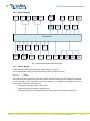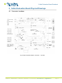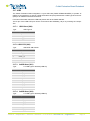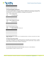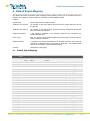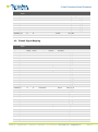
1
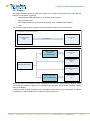
Colibri Evaluation Board Datasheet Colibri Evaluation Board Datasheet Revision History Date Doc. Rev. 11-Sept-12 Rev. 0.9 Board Version V3.1 Changes Preliminary Release 02-Oct-12 Rev. 1.0 V3.1 Added JTAG voltage warning in Section 3.8 09-Jan-13 Rev. 1.1 V3.1 Updated links to Toradex websites 23-Aug-13 Rev. 1.2 V3.1 - In the section 3.12.1 on page 33 the connector X21 is female and not male. - In the section 3.18.1 on page 38 the connector designator is X33. - In the section 3.18.3 on page 38 the connector designator is X37. - In the section 4.1 on page 39 the signals SODIMM_64 to SODIMM_70 have been modified with the correct values of the external connector X20. - In the section 3.6.5 the pins from 7 to 11 have been modified with the correct signal name. 03-Dec-2013 Rev. 1.3 V3.1 - In the section 3.6.5 on page 20 and 21, added color mapping (24bpp) data and notes. - In the section 3.6.8 on page 23, added color mapping (18bpp) data. 26-May-2014 Rev. 1.4 V3.1 - Section 1.2.8, Quick-Start Instructions: section name changed to Quick-Start Instructions from Installation. Minor corrections. - Section 3.20, Real-Time Clock (RTC): added section for RTC and Jumper (JP23) setting details. 12-June-2014 Rev. 1.5 V3.1 - Section 3.14, 2xRS232 (X25): added comments/remarks for pins U1, U4, U6, and U9 in the table. 23-Sept-2014 Rev. 1.6 V3.1 - Section 1.1.2, Colibri modules migration and compatibility guide: added Colibri Compatibility Guide download link. - Section 3.6.5, Generic Display (X20): Brief description about the Generic Display connector X20 has been added. Color mapping details have been modified in the table. 14-Oct-2014 Rev. 1.7 V3.2 - Section 2, Colibri Evaluation Board Physical Drawings: Fig. 2 and Fig. 3 have been updated. Connector X38 details have been added in the table. - Section 3.2, CAN: connector X38, jumper connectors JP4 and JP5 details have been added. - Section 3.11, Ethernet: jumper connector JP3 details have been added. - Section 3.13, Parallel Camera Interface: connector X22 pin-out details have been modified in the table. Notes have been added regarding Colibri Evaluation board V3.2 compatibility issue with Colibri Evaluation Board V3.1 and Analogue Camera Module (ACM) V1.1. - Section 3.16, USB to Serial Connector: jumpers JP20 and JP21 details have been added. - Section 5, PCB Revision: PCB revision details have been added. Toradex AG l Altsagenstrasse 5 l 6048 Horw l Switzerland l +41 41 500 48 00 l www.toradex.com l [email protected] Page | 2 Colibri Evaluation Board Datasheet Contents 1. Introduction ........................................................................................................................................... 5 1.1. Reference Documents ......................................................................................................................... 5 1.1.1 Colibri Computer Modules ........................................................................................................... 5 1.1.2 Colibri modules migration and compatibility guide ................................................................... 5 1.1.3 Pushbutton On/Off controller datasheet .................................................................................... 5 1.1.4 USB Hub datasheet ...................................................................................................................... 5 1.2. Features ................................................................................................................................................. 5 1.2.1 Overview ........................................................................................................................................ 5 1.2.2 User Interface ................................................................................................................................ 6 1.2.3 Communication ............................................................................................................................. 6 1.2.4 GPIO Usage Area ......................................................................................................................... 6 1.2.5 CPU Bus ......................................................................................................................................... 6 1.2.6 Block Diagram ............................................................................................................................... 7 1.2.7 Power Supply................................................................................................................................. 7 1.2.8 Quick-Start Instructions ................................................................................................................ 8 2. 3. Colibri Evaluation Board Physical Drawings .................................................................................. 9 2.1. Connector Locations............................................................................................................................. 9 2.2. Mechanical Drawing ........................................................................................................................... 11 Colibri Evaluation Board Connectors ............................................................................................ 12 3.1. Colibri Module (X1) ............................................................................................................................. 12 3.2. CAN....................................................................................................................................................... 12 3.2.1 CAN (X2 - Top) ............................................................................................................................ 12 3.2.2 CAN TX/RX (X38) ....................................................................................................................... 12 3.3. RS422/485 ........................................................................................................................................... 13 3.3.1 RS422/485 (X2 - Bottom) .......................................................................................................... 13 3.4. User Extension .................................................................................................................................... 14 3.4.1 User Extension (X3) ................................................................................................................... 14 3.5. Power CTRL ........................................................................................................................................ 16 3.5.1 Power CTRL (X4) ........................................................................................................................ 16 3.6. Display .................................................................................................................................................. 17 3.6.1 DVI-I Connector (X5) .................................................................................................................. 18 3.6.2 HDMI/VGA to Colibri (X6) .......................................................................................................... 18 3.6.3 Generic Touch-Screen (X16) .................................................................................................... 19 3.6.4 LVDS Connector (X18) .............................................................................................................. 19 3.6.5 Generic Display (X20) ................................................................................................................ 20 3.6.6 LCD Inverter (X23) ...................................................................................................................... 21 3.6.7 VGA (X24) .................................................................................................................................... 21 3.6.8 Unified TFT Interface (X34) ....................................................................................................... 22 3.7. GPIO Usage ........................................................................................................................................ 24 3.7.1 GPIO 1 Male (X8 Row A) ........................................................................................................... 24 3.7.2 GPIO 1 Female (X9) ................................................................................................................... 25 3.7.3 Function 1 Male (X8 Row B) ..................................................................................................... 25 3.7.4 Function 1 Female (X7).............................................................................................................. 26 3.7.5 Function 2 Male (X11 Row A) ................................................................................................... 27 3.7.6 Function 2 Female (X12) ........................................................................................................... 28 3.7.7 GPIO 2 Male (X11 Row B) ........................................................................................................ 28 3.7.8 GPIO 2 Female (X10) ................................................................................................................. 29 Toradex AG l Altsagenstrasse 5 l 6048 Horw l Switzerland l +41 41 500 48 00 l www.toradex.com l [email protected] Page | 3 Colibri Evaluation Board Datasheet 3.8. JTAG ..................................................................................................................................................... 30 3.8.1 JTAG to Host (X13) .................................................................................................................... 30 3.8.2 JTAG to Colibri (X19) ................................................................................................................. 31 3.8.3 JTAG to Colibri (X28) ................................................................................................................. 31 3.9. Analog IO ............................................................................................................................................. 32 3.9.1 Analog IO (X14)........................................................................................................................... 32 3.10. SD Card / MMC ............................................................................................................................... 32 3.10.1 SD Card / MMC (X15) ................................................................................................................ 32 3.11. Ethernet ............................................................................................................................................ 33 3.11.1 Ethernet (X17) ............................................................................................................................. 33 3.12. LEDs / Switches .............................................................................................................................. 34 3.12.1 LED/Switches (X21) ................................................................................................................... 34 3.13. Parallel Camera Interface (X22) ................................................................................................... 35 3.14. 2xRS232 (X25) ................................................................................................................................ 37 3.15. Audio ................................................................................................................................................. 38 3.15.1 3xAudio Jack (X26)..................................................................................................................... 38 3.16. USB to Serial Connector ................................................................................................................ 38 3.16.1 USB to Serial Connector (X27) ................................................................................................. 38 3.17. USB ................................................................................................................................................... 39 3.17.1 USB Client (X29) ......................................................................................................................... 39 3.17.2 USB OTG (X30) .......................................................................................................................... 39 3.17.3 2xUSB Host (X31) ....................................................................................................................... 39 3.17.4 2xUSB Host (X32) ....................................................................................................................... 39 3.18. Power Supply Connectors ............................................................................................................. 40 3.18.1 Power Supply (X33) .................................................................................................................... 40 3.18.2 Power Supply Jack (X35) .......................................................................................................... 40 3.18.3 Power OUT Jack (X37) .............................................................................................................. 40 3.19. 4. Real-Time Clock (RTC) .................................................................................................................. 40 Default Signal Mapping ..................................................................................................................... 41 4.1. Default Signal Mapping ...................................................................................................................... 41 4.2. Default Signal Mapping ...................................................................................................................... 42 5. PCB Revision ...................................................................................................................................... 44 6. RoHS Compliance .............................................................................................................................. 44 Toradex AG l Altsagenstrasse 5 l 6048 Horw l Switzerland l +41 41 500 48 00 l www.toradex.com l [email protected] Page | 4 Colibri Evaluation Board Datasheet 1. Introduction The Colibri Evaluation Board is designed to be a flexible development environment to explore the functionality and performance of the Colibri product family, and includes support for the additional/enhanced functionality on the Colibri T20 and Colibri T30, the Toradex modules which feature the NVIDIA® Tegra™ 2 and Tegra 3 processors. 1.1. Reference Documents For detailed technical information about suitable computer modules, please refer to the documents listed below. 1.1.1 Colibri Computer Modules An overview of the Colibri product family: http://www.toradex.com/products/colibri-arm-modules/colibri-arm-computer-modules 1.1.2 Colibri modules migration and compatibility guide http://docs.toradex.com/100188-colibri-migration-and-design-guide.pdf http://docs.toradex.com/102216-colibri-compatibility-guide.xlsx 1.1.3 Pushbutton On/Off controller datasheet http://cds.linear.com/docs/Datasheet/2954fb.pdf 1.1.4 USB Hub datasheet http://www.smsc.com/media/Downloads_Public/Data_Sheets/251xb.pdf 1.2. Features 1.2.1 Overview The Colibri Evaluation Board provides the following features and communication interfaces: 4x USB 2.0 port through on board USB Hub USB 2.0 OTG Micro-AB connectors for host and host/client USB Client Type B port (shared with the OTG) USB Type B port (optionally connected to FF UART via USB to serial converter) RJ45 Ethernet (10/100 Mbit) SD/MMC 4 bit Digital (TDMS) and Analog (VGA) interfaces on a single DVI-I connector Analog VGA interface on a 15 way D-type connector Single channel LVDS interface (up to 24 bit colour) Digital RGB interface (up to 24 bit colour) Unified TFT Interface with built in resistive touch for direct LCD panel connection Audio I/O on 3.5mm stereo jacks 2x RS232 Serial Interfaces IrDA 1x RS422/485 Serial Interface I2C, SPI, PWM, Analog inputs 1x CAN 2.0B Interface (up to 1Mbit/s) Real-time clock with battery backup Toradex AG l Altsagenstrasse 5 l 6048 Horw l Switzerland l +41 41 500 48 00 l www.toradex.com l [email protected] Page | 5 Colibri Evaluation Board Datasheet Resistive touch screen connector LEDs and Switches CPU Bus available on a connector Extremely Flexible and easy to use GPIO breakout and jumper area allowing easy signal rerouting, external connection and measurement/probing JTAG Parallel Camera Interface 1.2.2 User Interface The Colibri Evaluation Board provides an analog VGA connector to attach a standard computer monitor. It also provides HDMI/VGA video output through a DVI-I connector for those Colibri modules which support this feature. LCD panels can be directly connected through the digital RGB interface port. Since there is no standard connector for LCD panels, users usually need to build their own connector interface which attaches to the generic display header provided by the Evaluation Board. To simplify the connection of certain LCD panels, there is also a dedicated connector for the EDT Unified TFT Interface on board. This Interface has a built in resistive touch on the same connector. A variety of LCD panels with integrated touch support for evaluation purposes are available from the Toradex Webshop. The Colibri Evaluation Board also features a single channel LVDS interface for direct connection of LCD panels which support 18/24bit, single channel LVDS interfaces. Furthermore the Colibri Evaluation Board provides switches, buttons and LEDs for simple user interaction. Audio input and output is available on standard 3.5mm jacks. 1.2.3 Communication Commonly used communication functions are fully implemented on the Colibri Evaluation Board and include: 10/100Mb Ethernet, 4x USB 2.0 Host through USB On board USB Hub, USB OTG micro AB, 2x RS232, 1x RS485/422, USB to serial UART interface, 1x IrDA serial port, and a CAN 2.0b interface. For all these communication channels the industry standard connectors are provided on-board. The Parallel Camera Interface provides an easy way for interfacing CMOS and CCD sensors. An SDCard/MMC socket can be used to add storage devices or additional functions to the system. 1.2.4 GPIO Usage Area The GPIO breakout and jumper area provides a flexible mechanism for changing the hardware configuration and signal routing for a large number of SODIMM pins, including all of those which are GPIO capable. All the SODIMM pins and the standard function signals are described on the silkscreen in order to allow the user to identify required signals on the connector, without having to reference the board schematics. This enables the user to: - Change the factory set mapping of Colibri GPIOs to Evaluation Board functions. - Disconnect a Colibri GPIO from the standard function on the Evaluation Board, and instead connect it to an external interface or device. 1.2.5 CPU Bus The entire 16-/32-Bit bus of Colibri modules that support the external system bus is accessible through an extension connector. This offers to the user the possibility to interface custom hardware, such as FPGAs, directly to the system bus. The extension connector also provides both 3.3V and 5V power supplies. Toradex AG l Altsagenstrasse 5 l 6048 Horw l Switzerland l +41 41 500 48 00 l www.toradex.com l [email protected] Page | 6 Colibri Evaluation Board Datasheet 1.2.6 Block Diagram RS422/ 485 IrDA PWM PWM PWM ADCs ADCs USB ADCs USB RS232 RS232 CAN LEDs Switches USB OTG Serial SPI 4 Port USB Hub JTAG GPIOs Resistive Touch Colibri Module Camera Interface PWM PWM PWM ADCs ADCs PWM ADCs CPU Bus PWM PWM PWM ADCs ADCs ADCs ADCs Audio I/O Ethernet RTC SD/MMC Power Supply DVI-I Generic Display Unified Display Interface RGB VGA RGB LVDS Fig.1 Colibri Evaluation Board Block Diagram 1.2.7 Power Supply Colibri Evaluation Board has a wide input voltage range of 7-27V DC. The on-board power supply provides the following supplies (maximum power). 5V / 5A 3.3V / 5A (25W) (16.5W) The supply is protected against reverse input voltage polarity and short circuits, limiting the maximum current to about 5A. However the protection diode in the input voltage path is thermally not designed to carry that high current, especially at low input voltages. If your application dissipates more than 20W, please consider one of the following: - Work with a high input voltage, close to 24V - Add a heat-sink to the polarity protection diode - Short the polarity protection diode with a wire (removes the reverse polarity protection!) Toradex AG l Altsagenstrasse 5 l 6048 Horw l Switzerland l +41 41 500 48 00 l www.toradex.com l [email protected] Page | 7 Colibri Evaluation Board Datasheet 1.2.8 Quick-Start Instructions Perform the following steps to quick-start the Colibri Evaluation Board: 1. Insert a Colibri Module in the SODIMM socket X1 on the Colibri Evaluation Board. 2. Plug in a VGA monitor on the corresponding connector X24, a keyboard and a mouse into the available USB host ports. 3. Connect an external power supply to the board by the X33 or X35 connector (7-24V, 3W min, depending on your peripherals). 4. Turn on the external power supply. 5. Push down the power button SW7 on the Colibri Evaluation Board and the preinstalled operating system boots. For a detailed documentation of the software as well as for the newest bootloader and software images please refer to the Toradex Developer Website: http://developer.toradex.com Toradex AG l Altsagenstrasse 5 l 6048 Horw l Switzerland l +41 41 500 48 00 l www.toradex.com l [email protected] Page | 8 Colibri Evaluation Board Datasheet 2. Colibri Evaluation Board Physical Drawings 2.1. Connector Locations Power Supply X37 Power OUT JP28 SW7 X35 X16 X23 Touch JP24 JP8 X4 Power CTRL Power Supply Generic RGB Dislay Backlight Power ON/OFF X33 JP9 X20 X18 LVDS X34 Unified TFT Interface X24 JP7 JP10 X27 X7 USB Serial Out X8 JP14 JP15 GPIO Usage X9 Recovery Mode SW9 X38 X2 X5 X6 HDMI/VGA to Colibri (Tegra only) X19 JTAG to Colibri JP5 JP4 JP23 JP26 Top: CAN Bottom:RS422/485 JP12 JP16 X28 JTAG to Colibri BAT1 X32 X1 X14 Analog IO X26 X17 Ethernet JP3 JP18 JP19 JP20 JP17 JP21 X25 JP25 2 X RS232 X11 X31 USB 1/2 GPIO Usage X12 CIF X22 Switches 5 4 3 2 1 X36 4 3 2 1 IrDA LEDs USB 3/4 Colibri X10 6 HDMI/VGA (Tegra only) JP6 JP27 JP13 JP11 3 X 3.5mm Audio Jack VGA X15 JP29 LED/Switches X21 JTAG to Host X13 X30 X3 JP2 X29 SW8 USB OTG USB Client (Shared) Reset User Extension SD Card/MMC Fig.2 Colibri Evaluation Board connectors – Top Side Toradex AG l Altsagenstrasse 5 l 6048 Horw l Switzerland l +41 41 500 48 00 l www.toradex.com l [email protected] Page | 9 Colibri Evaluation Board Datasheet Ref Description Remarks X1 Colibri SODIMM X2 CAN – RS422/485 X3 User Extension X4 Power CTRL X5 HDMI/VGA Through DVI-I connector, only for modules which support this feature. X6 HDMI/VGA to Colibri Only for modules which support this feature X7 Function Tap X8 Jumper Array X9 SODIMM breakout area X10 SODIMM breakout area X11 Jumper Array X12 Function Tap X13 JTAG to Host X14 Analog IO X15 SD Card/MMC X16 Generic Touch-Screen X17 Ethernet X18 LVDS X19 JTAG to Colibri X20 Generic Display X21 LED/Switches X22 Parallel Camera X23 LCD Inverter X24 VGA X25 2x RS232 X26 3x Audio Jack X27 USB to Serial Connector X28 JTAG to Colibri X29 USB Client Shared with the connector X30 X30 USB OTG Shared with the connector X29 X31 2x USB HOST Port 1 and 2 X32 2x USB HOST Port 3 and 4 X33 Power Supply Screw Block Terminal X34 Unified TFT Interface X35 Power Supply Jack X36 IrDA X37 Power OUT X38 CAN TX/RX Toradex AG l Altsagenstrasse 5 l 6048 Horw l Switzerland l +41 41 500 48 00 l www.toradex.com l [email protected] Page | 10 Colibri Evaluation Board Datasheet 2.2. Mechanical Drawing Fig.3 Colibri Evaluation Board Mechanical Drawing – Top Side Toradex AG l Altsagenstrasse 5 l 6048 Horw l Switzerland l +41 41 500 48 00 l www.toradex.com l [email protected] Page | 11 Colibri Evaluation Board Datasheet 3. Colibri Evaluation Board Connectors 3.1. Colibri Module (X1) Type: SODIMM 200 Socket. Manufacturer: Tyco Electronics - 1473005-1. For the pin-out of the Colibri modules please refer to the Colibri Datasheets and Migration Guide for which a link is listed in chapter 1.1.2 Please note, that not all Colibri modules provide the same features (e.g.: the PXA300 does not have audio and touch-screen functionality). 3.2. CAN The Colibri Evaluation Board uses the Microchip MCP2515T-I/ST controller and the Microchip MCP2551T-I/SN CAN transceiver to implement the CAN 2.0b interface. The CAN port is electrically isolated from the system power supply. The CAN interface is available on the top part of the connector X2. The CAN connector provides the ability to optionally connect the isolated power supply to connector pins in order to provide power to external CAN nodes. Jumper assembled X2 pin number Power on X2 JP26 U6 CAN_PGND JP27 U9 CAN_PW 3.2.1 CAN (X2 - Top) Type: DSUB9 Male Pin Nr. Signal Name U1 NC U2 CAN_L U3 CAN_GND U4 NC Not connected U5 NC Not connected U6 CAN_PGND U7 CAN_H U8 NC U9 CAN_V+ 3.2.2 IO Type Voltage Pullup/Pulldown Not connected IO +5V PWR PWR IO +5V Not connected PWR +5V CAN TX/RX (X38) Colibri VFxx and Colibri iMX6 features on-module CAN interface. This is a module specific feature and may not be supported by all the computer-on-modules in the Colibri family. For more details, refer to the datasheet of Colibri computer-on-modules. http://developer.toradex.com/hardware-resources/arm-family/colibri-module/can-(controller-areanetwork)-on-colibri-module Toradex AG l Altsagenstrasse 5 l 6048 Horw l Switzerland l +41 41 500 48 00 l www.toradex.com l [email protected] Page | 12 Colibri Evaluation Board Datasheet Connector X38 along with jumpers JP4 and JP5, facilitates evaluation/testing of the on-module CAN interface. Jumper JP4 and JP5 are used to connect or disconnect the on-board CAN controller signals with the CAN transceiver. Jumper Signal JP4 CAN_TX JP5 CAN_RX In order to test the on-module CAN interface using Colibri Evaluation Board, please use the following hardware configurations: a) Open circuit jumper JP4 & JP5. b) Using jumper wires connect the CAN_TX & CAN_RX signals from Colibri module (using GPIO breakout connector) to the connector X38 respectively. c) CAN transceiver output is available on the top part of the connector X2. Type: 1x2Pin Female, 2.54mm Pin Nr. Signal Name IO Type Voltage 1 CAN_TX O +3.3V 2 CAN_RX I +3.3V Pullup/Pulldown 3.3. RS422/485 The RS422/485 interface is implemented using the Analog Devices ADM3491ARZ transceiver. The RS422/485 interface is connected to BT UART of the Colibri Module. This UART port is shared with the RS232 transceiver. The jumpers JP11, JP12, JP13, JP14, JP15, JP16 provide hardware configuration for this interface: Jumper Status Function JP11 CLOSED ECHO disabled (the sender cannot read the message just sent) JP12, JP14 CLOSED Insert the 120ohm bus termination (for RS422) JP13, JP15 OPEN Full Duplex Configuration JP16 CLOSED The upper RS232 is disable 3.3.1 RS422/485 (X2 - Bottom) Type: DSUB9 Male Pin Nr. Signal Name IO Type L1 GND L2 NC Not connected L3 NC Not connected L4 RXD+ IO L5 RXD- IO L6 NC Not connected L7 NC Not connected L8 TXD+ IO L9 TXD- IO Voltage Pullup/Pulldown PWR Toradex AG l Altsagenstrasse 5 l 6048 Horw l Switzerland l +41 41 500 48 00 l www.toradex.com l [email protected] Page | 13 Colibri Evaluation Board Datasheet 3.4. User Extension The User extension connector provides the CPU bus and a power supply for additional external Hardware. 3.4.1 User Extension (X3) Type: DIN41612 96Pin Female Pin Nr. Signal Name IO Type Voltage A1 DATA_0 IO +3V3 A2 DATA_3 IO +3V3 A3 DATA_5 IO +3V3 A4 DATA_8 IO +3V3 A5 DATA_11 IO +3V3 A6 DATA_13 IO +3V3 A7 DATA_16 IO +3V3 A8 DATA_19 IO +3V3 A9 DATA_21 IO +3V3 A10 DATA_24 IO +3V3 A11 DATA_27 IO +3V3 A12 DATA_29 IO +3V3 A13 +3V3 PWR +3V3 A14 ADDR_0 O +3V3 A15 ADDR_3 O +3V3 A16 ADDR_6 O +3V3 A17 ADDR_8 O +3V3 A18 ADDR_11 O +3V3 A19 ADDR_14 O +3V3 A20 ADDR_16 O +3V3 A21 ADDR_19 O +3V3 A22 ADDR_22 O +3V3 A23 ADDR_24 O +3V3 A24 DQM1 O +3V3 A25 +5V PWR +5V A26 WE# I +3V3 A27 EXT_CS_0# I +3V3 A28 RD_WR# I +3V3 A29 I2C_SDA IO +3V3 A30 SSP_FRM IO +3V3 A31 PWE# I +3V3 A32 EXT_IO_1 I +3V3 B1 DATA_1 IO +3V3 B2 GND B3 DATA_6 B4 DATA_9 B5 +3V3 B6 DATA_14 Pullup/Pulldown 100k to +3V3 4k7 to +3V3 PWR IO +3V3 IO +3V3 PWR IO +3V3 Toradex AG l Altsagenstrasse 5 l 6048 Horw l Switzerland l +41 41 500 48 00 l www.toradex.com l [email protected] Page | 14 Colibri Evaluation Board Datasheet Pin Nr. Signal Name IO Type Voltage B7 DATA_17 IO +3V3 B8 +3V3 B9 DATA_22 IO +3V3 B10 DATA_25 IO +3V3 B11 +3V3 B12 DATA_30 B13 GND B14 ADDR_1 B15 ADDR_4 B16 GND B17 ADDR_9 O +3V3 B18 ADDR_12 O +3V3 B19 +5V B20 ADDR_17 O +3V3 B21 ADDR_20 O +3V3 B22 GND B23 ADDR_25 O +3V3 B24 DQM_2 O +3V3 B25 GND B26 EXT_CS_1# B27 GND B28 RDY IO B29 +5V PWR B30 SSP_TXD B31 GND B32 RESET_OUT# O +3V3 C1 DATA_2 IO +3V3 C2 DATA_4 IO +3V3 C3 DATA_7 IO +3V3 C4 DATA_10 IO +3V3 C5 DATA_12 IO +3V3 C6 DATA_15 IO +3V3 C7 DATA_18 IO +3V3 C8 DATA_20 IO +3V3 C9 DATA_23 IO +3V3 C10 DATA_26 IO +3V3 C11 DATA_28 IO +3V3 C12 DATA_31 IO +3V3 C13 +3V3 C14 ADDR_2 O +3V3 C15 ADDR_5 O +3V3 C16 ADDR_7 O +3V3 C17 ADDR_10 O +3V3 C18 ADDR_13 O +3V3 Pullup/Pulldown PWR PWR IO +3V3 PWR O +3V3 O +3V3 PWR PWR PWR PWR IO +3V3 100k to +3V3 PWR O +3V3 +3V3 PWR PWR Toradex AG l Altsagenstrasse 5 l 6048 Horw l Switzerland l +41 41 500 48 00 l www.toradex.com l [email protected] Page | 15 Colibri Evaluation Board Datasheet Pin Nr. Signal Name IO Type Voltage C19 Pullup/Pulldown ADDR_15 O +3V3 C20 ADDR_18 O +3V3 C21 ADDR_21 O +3V3 C22 ADDR_23 O +3V3 C23 DQM_0 O +3V3 C24 DQM_3 O +3V3 C25 +5V PWR C26 OE# O +3V3 C27 EXT_CS_2# IO +3V3 100k to +3V3 C28 I2C_SCL IO +3V3 4k7 to +3V3 C29 SSP_SCLK IO +3V3 C30 SSP_RXD I +3V3 C31 EXT_IO_0 IO +3V3 C32 EXT_IO_2 IO +3V3 3.5. Power CTRL Power control of the Colibri Evaluation Board is implemented using the Linear LTC2954 Pushbutton On/Off controller. For further information about the signals provided by this controller please refer to the datasheet. The Power CTRL connector X4 provides the Reset and Power Button control signals to be accessed by external logic. By assembling the Jumper JP28 it is possible to obtain an “Always On” behaviour: the Colibri Evaluation Board will start without waiting for the Power On button to be pushed. In addition the pin 3 of the connector X4 can be used in order to override the Pushbutton controller. The following table shows the behaviour of the board according to the level of the PWR_CTRL signal: PWR_CTRL Level Function 0V The Pushbutton controller is working normally 3.3V The Colibri Evaluation Board is Always On when power is applied 3.5.1 Power CTRL (X4) Type: 2 x 3Pin Header Female, 2.54mm Pin Nr. Signal Name IO Type 1 PWRBTN1 2 GND 3 PWR_CTRL I 4 INT# I 5 FORCE_OFF# I 6 RESET_EXT# IO Voltage I Pullup/Pulldown PU 100K to 1.9V PWR +3.3V max PD 100K PU 10K TO 3.3V PU 100K TO 3.3V +3V3 PU to +33V Toradex AG l Altsagenstrasse 5 l 6048 Horw l Switzerland l +41 41 500 48 00 l www.toradex.com l [email protected] Page | 16 Colibri Evaluation Board Datasheet 3.6. Display The Colibri Evaluation Board provides many options for connecting LCD panels and monitors, with the following four interfaces supported: - 18/24 bit digital RGB (depending on the installed Colibri module) - Single channel LVDS - DVI-I (Digital TDMS and Analog VGA, depending on the installed Colibri module) - VGA The following image shows the Display interface architecture that has been implemented: Only for Modules which support this interface Colibri DVI/VGA FFC Connector X6 DVI-I Connector X5 DVI + VGA FFC PXA270, PXA3XX RGB to LVDS converter (NS DS90C363B) LVDS LVDS Connector X18 Unified Display Interface Connector X34 Colibri digital RGB interface Generic Display Connector X20 RGB to VGA DAC (ADV7125KSTZ140) VGA VGA Connector X24 Almost any TFT or STN display can be connected to the LCD port of the Colibri module by simply connecting the necessary signals from connectors X16 and X20 (which provide standard 2.54mm pitch) to the display. Toradex provides a range of different tools and utilities to help with the easy configuration of different LCD panels. For details please refer to: http:/developer.toradex.com Toradex AG l Altsagenstrasse 5 l 6048 Horw l Switzerland l +41 41 500 48 00 l www.toradex.com l [email protected] Page | 17 Colibri Evaluation Board Datasheet 3.6.1 DVI-I Connector (X5) Pin Description 1 TMDS_DATA2_N I 2 TMDS_DATA2_P I 3 GND 4 NC 5 NC 6 DDC_CLK I 7 DDC_DATA I 8 CRT_VSYNC I 9 TMDS_DATA1_N I 10 TMDS_DATA1_P I 11 GND 12 NC 13 NC 14 DVI_5V PWR 15 GND PWR 16 HOTPLUG_DETECT O 17 TMDS_DATA0_N I 18 TMDS_DATA0_P 19 GND 20 NC 21 NC 22 GND 23 TMDS_CLK_P I 24 TMDS_CLK_N I C1 CRT_RED I C2 CRT_GREEN I C3 CRT_BLUE I C4 CRT_HSYNC I C5 GND 3.6.2 I/O Type Voltage Pull-up/Pull-down PWR PWR +5V I PWR PWR PWR HDMI/VGA to Colibri (X6) Connector type: Hirose FH12-24S-0.5SV(55) Pin Signal Name I/O Type Voltage 1 GND 2 TMDS_CLK_P I +3.3V 3 TMDS_CLK_N I +3.3V 4 GND 5 TMDS_DATA0_P I +3.3V 6 TMDS_DATA0_N I +3.3V 7 GND 8 TMDS_DATA1_P I +3.3V 9 TMDS_DATA1_N I +3.3V 10 GND Pull-up/Pull-down PWR PWR PWR PWR Toradex AG l Altsagenstrasse 5 l 6048 Horw l Switzerland l +41 41 500 48 00 l www.toradex.com l [email protected] Page | 18 Colibri Evaluation Board Datasheet Pin Signal Name 11 TMDS_DATA2_P I +3.3V 12 TMDS_DATA2_N I +3.3V 13 NC 14 HOTPLUG_DETECT O +3.3V 15 DDC_CLK I +5V 1.8KR to +5V 16 DDC_DATA I +5V 1.8KR to +5V 17 GND 18 CRT_RED 19 GND 20 CRT_GREEN 21 GND 22 CRT_BLUE I +3.3V 23 CRT_VSYNC I +3.3V 24 CRT_HSYNC I +3.3V 3.6.3 I/O Type Voltage Pull-up/Pull-down PWR I +3.3V PWR I +3.3V PWR Generic Touch-Screen (X16) Part number: Samtec TSW-103-07-G-D (Header Male 2x3 2.54mm pitch) Pin Nr. Signal Name IO Type IO Type 1 GND 2 TOUCH_TSMY 20 O +3V3 3 TOUCH_TSMX 16 O +3V3 4 TOUCH_TSPY 18 O +3V3 5 TOUCH_TSPX 14 O +3V3 6 TOUCH_WIPER 2 (via R95) O +3.3V 3.6.4 LVDS Connector (X18) Pullup/Pulldown PWR Connector type: Hirose DF13A-20DP-1.25v(56) Pin Signal Name Description 1 LVDS_5V 5V power supply pin 2 LVDS_3.3V 3.3V power supply pin 3 GND 4 SEL1 Connected to LVDS_3.3V or GND via Jumper JP7. The default value is GND 5 LVDS_OUT0_N The negative LVDS output number 0 6 GND 7 LVDS_OUT0_P The positive LVDS output number 0 8 LVDS_OUT1_N The negative LVDS output number 1 9 GND 10 LVDS_OUT1_P The positive LVDS output number 1 11 LVDS_OUT2_N The negative LVDS output number 2 12 GND 13 LVDS_OUT2_P The positive LVDS output number 2 14 LVDS_CLK_N The negative LVDS clock signal 15 GND 16 LVDS_CLK_P The positive LVDS clock signal Toradex AG l Altsagenstrasse 5 l 6048 Horw l Switzerland l +41 41 500 48 00 l www.toradex.com l [email protected] Page | 19 Colibri Evaluation Board Datasheet Pin Signal Name Description 17 BL_ON Back Light control signal 18 GND 19 SEL2 Connected to LVDS_5V, LVDS_3.3V or GND via Jumper JP8. The default value is 5V 20 SEL3 Connected to LVDS_3.3V or GND via Jumper JP9. The default value is LVDS_3.3V 3.6.5 Generic Display (X20) Generic display connector X20 can support up-to 24 bit RGB interface, depending upon the Colibri module installed on the evaluation board. The 18 bit color mapping is compatible with all the computer-on-modules in the Colibri family. For more details please see the relevant Colibri module datasheet. Part number: Samtec TSW-125-07-G-D (Header Male 2x25 2.54mm pitch) Pin Nr. Signal Name Color Mapping 18bpp IO Type Voltage 1 GND 2 LCD_PCLK_WR OI +3V3 3 LCD_LCLK_A0 O +3V3 4 LCD_FCLK_RD O +3V3 5 GND PWR PWR 6 LCD_D_12 RED 0 O +3V3 7 LCD_D_13 RED 1 O +3V3 8 LCD_D_14 RED 2 O +3V3 9 LCD_D_15 RED 3 O +3V3 10 LCD_D_16 RED 4 O +3V3 11 LCD_D_17 RED 5 O +3V3 12 GND 13 LCD_D_6 GREEN 0 O +3V3 14 LCD_D_7 GREEN 1 O +3V3 15 LCD_D_8 GREEN 2 O +3V3 16 LCD_D_9 GREEN 3 O +3V3 17 LCD_D_10 GREEN 4 O +3V3 18 LCD_D_11 GREEN 5 O +3V3 19 GND 20 LCD_D_0 BLUE 0 O +3V3 21 LCD_D_1 BLUE 1 O +3V3 22 LCD_D_2 BLUE 2 O +3V3 23 LCD_D_3 BLUE 3 O +3V3 24 LCD_D_4 BLUE 4 O +3V3 25 LCD_D_5 BLUE 5 O +3V3 26 GND 27 L_BIAS 28 Pullup/Pulldown PWR PWR PWR PWR I +3V3 +V_DISPLAY PWR JP4 selects +3V3 or +5V 29 +V_DISPLAY PWR JP4 selects +3V3 or +5V 30 TP9 IO 31 P10 IO 32 GND PWR Toradex AG l Altsagenstrasse 5 l 6048 Horw l Switzerland l +41 41 500 48 00 l www.toradex.com l [email protected] Page | 20 Colibri Evaluation Board Datasheet Pin Nr. Signal Name 33 TOUCH_TSMY O 34 TOUCH_TSMX O 35 TOUCH_TSPY O 36 TOUCH_TSPX O 37 BL_ON O 38 GND_DISPINV PWR 39 5V_DISPINV PWR 40 GND_DISPINV PWR 41 GND PWR 42 GND PWR 43 LCD_D_22 O +3V3 44 LCD_D_23 O +3V3 45 LCD_D_20 O +3V3 46 LCD_D_21 O +3V3 47 LCD_D_18 O +3V3 48 LCD_D_19 O +3V3 49 3.3V_DISP PWR 50 TOUCH_WIPER 3.6.6 Color Mapping 18bpp IO Type Pullup/Pulldown +3V3 100k to GND +5V O LCD Inverter (X23) Part number: 3M 961105-6404-AR (Header Male 1x5 2.54mm pitch) Pin Nr. Signal Name IO Type 1 5V_DISPINV PWR 2 GND_DISPINV PWR 3 BL_ON 4 GND_DISPINV 5 NC 3.6.7 Voltage O Voltage Pullup/Pulldown +5V +3V3 100k to GND PWR Not connected VGA (X24) Type: High Density DSUB15 Pin Nr. Signal Name IO Type 1 EXT_RED O 2 EXT_GREEN O 3 EXT_BLUE O 4 NC 5 GND PWR 6 GND PWR 7 GND PWR 8 GND PWR 9 GND PWR 10 GND PWR 11 NC Not connected 12 NC Not connected 13 EXT_HSYNC Voltage Pullup/Pulldown Not connected O +5V Toradex AG l Altsagenstrasse 5 l 6048 Horw l Switzerland l +41 41 500 48 00 l www.toradex.com l [email protected] Page | 21 Colibri Evaluation Board Datasheet Pin Nr. Signal Name IO Type 14 EXT_VSYNC O 15 NC 3.6.8 Voltage Pullup/Pulldown +5V Not connected Unified TFT Interface (X34) This RGB display interface uses the EDT Unified TFT Display Interface pin out, for which there are a wide variety of displays of different sizes and resolutions available. These displays are connected to the Colibri Evaluation Board directly via a 40 way FFC. The EDT Unified TFT Interface also features a resistive touch screen interface on the same FFC, providing support for displays which have integrated touch. For further information about this interface and the available LCD panels, please refer to the Toradex developer website: http://developer.toradex.com/knowledge-base/edt-unified-interface-display-family Toradex AG l Altsagenstrasse 5 l 6048 Horw l Switzerland l +41 41 500 48 00 l www.toradex.com l [email protected] Page | 22 Colibri Evaluation Board Datasheet Connector type: Hirose FH12-40S-0.5SV(55) Pin Signal Name Color Mapping 18bpp I/O Type Voltage 1 GND PWR 2 GND PWR 3 +3.3V PWR +3.3V 4 +3.3V PWR +3.3V 5 BL_ON O +3.3V 6 PWM_A O +3.3V 7 RESET_OUT# O +3.3V 8 LCD_D_5 BLUE 5 O +3.3V 9 LCD_D_4 BLUE 4 O +3.3V 10 LCD_D_3 BLUE 3 O +3.3V 11 LCD_D_2 BLUE 2 O +3.3V 12 LCD_D_1 BLUE 1 O +3.3V 13 LCD_D_0 BLUE 0 O +3.3V 14 GND 15 LCD_D_11 GREEN 5 O +3.3V 16 LCD_D_10 GREEN 4 O +3.3V 17 LCD_D_9 GREEN 3 O +3.3V 18 LCD_D_8 GREEN 2 O +3.3V 19 LCD_D_7 GREEN 1 O +3.3V 20 LCD_D_6 GREEN 0 O +3.3V 21 GND 22 LCD_D_17 RED 5 O +3.3V 23 LCD_D_16 RED 4 O +3.3V 24 LCD_D_15 RED 3 O +3.3V 25 LCD_D_14 RED 2 O +3.3V 26 LCD_D_13 RED 1 O +3.3V 27 LCD_D_12 RED 0 O +3.3V 28 LCD_PCLK_WR O +3.3V 29 GND 30 LCD_LCLK_A0 O +3.3V 31 LCD_FCLK_RD O +3.3V 32 LCD_BIAS O +3.3V 33 Connected to 3.3V or GND via assembly option. The default assembly is GND O +3.3V/GND 34 Connected to 3.3V or GND via assembly option. The default assembly is GND O +3.3V/GND 35 GND PWR 36 +3.3V PWR +3.3V 37 TOUCH_TSPY O +3.3V 38 TOUCH_TSMX O +3.3V 39 TOUCH_TSMY O +3.3V 40 TOUCH_TSPX O +3.3V PWR PWR PWR Toradex AG l Altsagenstrasse 5 l 6048 Horw l Switzerland l +41 41 500 48 00 l www.toradex.com l [email protected] Page | 23 Colibri Evaluation Board Datasheet 3.7. GPIO Usage The GPIO breakout connectors offer the flexibility to map the GPIOs of the Colibri module to either the on-board function or to external hardware. The factory setting is a straight through jumper setting, meaning that the X8-A row is connected straight to the X8-B row. This is also true for the connector X11. To allowing easy measurement, probing, and re-routing, all signals residing on the male header are also available on a female connector in parallel. To map SODIMM ping with the corresponding GPIO numbers which are specific to individual Colibri modules, please refer to the Migration Guide (see chapter 1.1.2). 3.7.1 GPIO 1 Male (X8 Row A) Type: 2x50Pin Male, 2.54mm Pin Nr. Signal Name IO Type Voltage A1 A2 +3V3 PWR +3V3 +3V3 PWR +3V3 A3 GND PWR A4 SODIMM_45 IO +3V3 A5 SODIMM_55 IO +3V3 A6 SODIMM_63 IO +3V3 A7 SODIMM_100 IO +3V3 A8 GND A9 SODIMM_102 IO +3V3 A10 SODIMM_104 IO +3V3 A11 VDD_FAULT# IO +3V3 A12 BATT_FAULT# IO +3V3 A13 SODIMM_44 IO +3V3 A14 SODIMM_76 IO +3V3 A15 +3V3 A16 SODIMM_70 IO +3V3 A17 SODIMM_60 IO +3V3 A18 SODIMM_58 IO +3V3 A19 SODIMM_78 IO +3V3 A20 SODIMM_72 IO +3V3 A21 SODIMM_80 IO +3V3 A22 GND A23 SODIMM_46 IO +3V3 A24 SODIMM_62 IO +3V3 A25 SODIMM_48 IO +3V3 A26 SODIMM_74 IO +3V3 A27 SODIMM_50 IO +3V3 A28 SODIMM_52 IO +3V3 A29 +3V3 A30 SODIMM_54 IO +3V3 A31 SODIMM_66 IO +3V3 A32 SODIMM_64 IO +3V3 Pullup/Pulldown PWR PWR PWR PWR Toradex AG l Altsagenstrasse 5 l 6048 Horw l Switzerland l +41 41 500 48 00 l www.toradex.com l [email protected] Page | 24 Colibri Evaluation Board Datasheet Pin Nr. Signal Name IO Type Voltage A33 SODIMM_57 IO +3V3 A34 SODIMM_61 IO +3V3 A35 SODIMM_136 IO +3V3 A36 GND A37 SODIMM_138 IO +3V3 A38 SODIMM_140 IO +3V3 A39 SODIMM_142 IO +3V3 A40 SODIMM_144 IO +3V3 A41 SODIMM_146 IO +3V3 A42 SODIMM_56 IO +3V3 A43 +3V3 A44 SODIMM_68 IO +3V3 A45 SODIMM_82 IO +3V3 A46 SODIMM_71 IO +3V3 A47 SODIMM_194 IO +3V3 A48 SODIMM_196 IO +3V3 A49 GND PWR A50 GND PWR 3.7.2 Pullup/Pulldown PWR PWR GPIO 1 Female (X9) Type: 1x50Pin Female, 2.54mm Pin-out identical to X8 Pins A1 to A50. 3.7.3 Function 1 Male (X8 Row B) Type: 2x50Pin Male, 2.54mm Pin Nr. Signal Name IO Type Voltage B1 +3V3 PWR B2 +3V3 PWR B3 GND PWR B4 SODIMM_45 IO +3V3 B5 SODIMM_55 IO +3V3 B6 SODIMM_63 IO +3V3 B7 SODIMM_100 IO +3V3 B8 GND B9 SODIMM_102 IO +3V3 B10 SODIMM_104 IO +3V3 B11 VDD_FAULT# IO +3V3 B12 BATT_FAULT# IO +3V3 B13 LCD_BIAS O +3V3 B14 LCD_D_0 O OLV B15 +3V3 B16 LCD_D_1 O +3V3 B17 LCD_D_2 O +3V3 B18 LCD_D_3 O +3V3 Pullup/Pulldown PWR PWR Toradex AG l Altsagenstrasse 5 l 6048 Horw l Switzerland l +41 41 500 48 00 l www.toradex.com l [email protected] Page | 25 Colibri Evaluation Board Datasheet Pin Nr. Signal Name IO Type Voltage B19 LCD_D_4 O +3V3 B20 LCD_D_5 O +3V3 B21 LCD_D_6 O +3V3 B22 GND B23 LCD_D_7 O +3V3 B24 LCD_D_8 O +3V3 B25 LCD_D_9 O +3V3 B26 LCD_D_10 O +3V3 B27 LCD_D_11 O +3V3 B28 LCD_D_12 O +3V3 B29 +3V3 B30 LCD_D_13 O +3V3 B31 LCD_D_14 O +3V3 B32 LCD_D_15 IO +3V3 B33 LCD_D_16 IO +3V3 B34 LCD_D_17 I +3V3 B35 LCD_D_18 O +3V3 B36 GND B37 LCD_D_19 O +3V3 B38 LCD_D_20 O +3V3 B39 LCD_D_21 O +3V3 B40 LCD_D_22 I +3V3 100k to +3V3 B41 LCD_D_23 I +3V3 100k to +3V3 B42 LCD_PCLK_WR I +3V3 100k to +3V3 B43 +3V3 B44 LCD_LCLK_AO O +3V3 100k to +3V3 B45 LCD_FCLK_RD IO +3V3 33k to +3V3 B46 BL_ON IO +3V3 68k to +3V3 B47 I2C_SDA IO +3V3 4k7 to +3V3 B48 I2C_SCL IO +3V3 4k7 to +3V3 B49 GND PWR B50 GND PWR 3.7.4 Type: Pullup/Pulldown PWR PWR PWR PWR Function 1 Female (X7) 1x50Pin Female, 2.54mm Pin-out identical to X8 Pins B1 to B50 Toradex AG l Altsagenstrasse 5 l 6048 Horw l Switzerland l +41 41 500 48 00 l www.toradex.com l [email protected] Page | 26 Colibri Evaluation Board Datasheet 3.7.5 Function 2 Male (X11 Row A) Type: 2x50Pin Male Pin Nr. Signal Name IO Type Voltage Pullup/Pulldown A1 +3V3 A2 UART_C_RXD I +3V3 A3 UART_C_TXD O +3V3 A4 UART_A_DTR O +3V3 A5 UART_A _CTS I +3V3 A6 UART_A _RTS O +3V3 A7 UART_A _DSR I +3V3 A8 GND A9 UART_A _DCD I +3V3 A10 UART_A _D_RXD I +3V3 A11 UART_A _D_TXD O +3V3 A12 UART_A _RI I +3V3 A13 UART_B_CTS I +3V3 A14 UART_B_RTS O +3V3 A15 +3V3 A16 UART_B_RXD I +3V3 A17 UART_B_TXD O +3V3 A18 MM_CD I +3V3 A19 MM_CLK O +3V3 A20 MM_CMD I +3V3 33k to +3V3 A21 MM_DAT_0 IO +3V3 68k to +3V3 A22 GND A23 MM_DAT_1 IO +3V3 68k to +3V3 A24 MM_DAT_2 IO +3V3 68k to +3V3 A25 MM_DAT_3 IO +3V3 68k to +3V3 A26 PWM_A O +3V3 A27 PWM_B O +3V3 RC-filter (3.3ms) A28 PWM_C O +3V3 RC-filter (3.3ms) A29 +3V3 A30 PWM_D O +3V3 RC-filter (3.3ms) A31 CAN_INT# IO +3V3 4k7 to +3V3 A32 SSP_FRM IO +3V3 A33 SSP_SCLK IO +3V3 A34 SSP_RXD I +3V3 A35 SSP_TXD O +3V3 A36 GND A37 EXT_CS_0# O +3V3 100k to +3V3 A38 EXT_CS_1# O +3V3 100k to +3V3 A39 EXT_CS_2# O +3V3 100k to +3V3 A40 EXT_IO_0 IO +3V3 A41 EXT_IO_1 IO +3V3 A42 EXT_IO_2 IO +3V3 PWR PWR PWR PWR PWR PWR Toradex AG l Altsagenstrasse 5 l 6048 Horw l Switzerland l +41 41 500 48 00 l www.toradex.com l [email protected] Page | 27 Colibri Evaluation Board Datasheet Pin Nr. Signal Name Voltage Pullup/Pulldown A43 +3V3 PWR A44 GND PWR A45 +3V3 PWR A46 GND PWR A47 USB_PE# O +3V3 100k to GND A48 USB_OC# O +3V3 100k to +3V3 A49 USBC_DET I +3V3 A50 GND 3.7.6 IO Type PWR Function 2 Female (X12) Type: 1x50Pin Female, 2.54mm Pin-out identical to X11 Pins A1 to A50 3.7.7 GPIO 2 Male (X11 Row B) Type: 2x50Pin Male, 2.54mm Pin Nr. Signal Name IO Type Voltage B1 +3V3 B2 SODIMM_19 IO +3V3 B3 SODIMM_21 IO +3V3 B4 SODIMM_23 IO +3V3 B5 SODIMM_25 IO +3V3 B6 SODIMM_27 IO +3V3 B7 SODIMM_29 IO +3V3 B8 GND B9 SODIMM_31 IO +3V3 B10 SODIMM_33 IO +3V3 B11 SODIMM_35 IO +3V3 B12 SODIMM_37 IO +3V3 B13 SODIMM_32 IO +3V3 B14 SODIMM_34 IO +3V3 B15 +3V3 B16 SODIMM_36 IO +3V3 B17 SODIMM_38 IO +3V3 B18 SODIMM_43 IO +3V3 B19 SODIMM_47 IO +3V3 B20 SODIMM_190 IO +3V3 B21 SODIMM_192 IO +3V3 B22 GND B23 SODIMM_49 IO +3V3 B24 SODIMM_51 IO +3V3 B25 SODIMM_53 IO +3V3 B26 SODIMM_59 IO +3V3 B27 SODIMM_28 IO +3V3 B28 SODIMM_30 IO +3V3 Pullup/Pulldown PWR PWR PWR PWR Toradex AG l Altsagenstrasse 5 l 6048 Horw l Switzerland l +41 41 500 48 00 l www.toradex.com l [email protected] Page | 28 Colibri Evaluation Board Datasheet Pin Nr. Signal Name B29 +3V3 B30 SODIMM_67 IO +3V3 B31 SODIMM_73 IO +3V3 B32 SODIMM_86 IO +3V3 B33 SODIMM_88 IO +3V3 B34 SODIMM_90 IO +3V3 B35 SODIMM_92 IO +3V3 B36 GND B37 SODIMM_105 IO +3V3 B38 SODIMM_107 IO +3V3 B39 SODIMM_106 IO +3V3 B40 SODIMM_135 IO +3V3 B41 SODIMM_133 IO +3V3 B42 SODIMM_127 IO +3V3 B43 +3V3 PWR B44 GND PWR B45 +3V3 PWR B46 GND PWR B47 SODIMM_129 IO +3V3 B48 SODIMM_131 IO +3V3 B49 SODIMM_137 IO +3V3 B50 GND 3.7.8 Type: IO Type Voltage Pullup/Pulldown PWR PWR PWR GPIO 2 Female (X10) 1x50Pin Female, 2.54mm Pin-out identical to X11 Pins B1 to B50 Toradex AG l Altsagenstrasse 5 l 6048 Horw l Switzerland l +41 41 500 48 00 l www.toradex.com l [email protected] Page | 29 Colibri Evaluation Board Datasheet 3.8. JTAG The Colibri Evaluation Board provides a JTAG interface to the JTAG port available on Colibri modules. Connector X19 is used to connect to the Colibri module JTAG connector with a flexible flat cable, and X13 provides an interface to an external JTAG device via a standard 2.54mm shrouded and keyed header. In addition, the Colibri evaluation Board features a spring loaded Pogo-pin connector X28 which is positioned directly underneath the installed Colibri module, allowing direct connection with the Colibri module JTAG test points, removing the need for the JTAG FFC connector. Different Colibri modules support JTAG interfaces with different voltage levels, and therefore Jumper JP29 must be used to set the correct JTAG voltage reference: JP29 Active 1-2 VREF_JTAG = +1.8V 2-3 VREF_JTAG = +3.3V Please note that, if the voltage is wrong, the module will be damaged! 3.8.1 JTAG to Host (X13) Type: 2x10Pin Header Male, 2.54mm Pin Nr. Signal Name IO Type 1 VREF_JTAG PWR 2 VREF_JTAG PWR 3 JTAG_TRST# I 4 GND 5 JTAG_TDI 6 GND 7 JTAG_TMS 8 GND 9 JTAG_TCK 10 GND 11 NC 12 GND 13 JTAG_TDO_R 14 GND 15 JTAG_SYSRESET# 16 GND 17 NC 18 GND 19 NC 20 GND Voltage Pullup/Pulldown +3V3 PWR I +3V3 PWR I +3V3 PWR I +3V3 PWR Not connected PWR I +3V3 PWR I +3V3 PWR Not connected PWR Not connected PWR Toradex AG l Altsagenstrasse 5 l 6048 Horw l Switzerland l +41 41 500 48 00 l www.toradex.com l [email protected] Page | 30 Colibri Evaluation Board Datasheet 3.8.2 JTAG to Colibri (X19) When inserting the Colibri module into the Colibri Evaluation Board please pay attention how you connect the 8 pin FCC cable which is used for the JTAG connection between the Colibri Evaluation Board and the Colibri: First plug in FCC cable into connector X2 of Colibri module (so the blue coloured supporting tape of the FCC cable is opposite to the Colibri PCB). Secondly, plug the Colibri module into the Colibri Evaluation Board. Finally, plug the FCC cable into connector X19 of Colibri Evaluation Board (the blue coloured supporting tape of the FCC cable is facing towards the Colibri module) Part number: GCT FFC2A30-08-T-L Pin Nr. Signal Name IO Type Voltage Pullup/Pulldown 1 JTAG_SYSRESET# O +3V3 - 2 JTAG_TDI O +3V3 - 3 JTAG_TDO I +3V3 - 4 JTAG_TCK O +3V3 - 5 JTAG_TRST# O +3V3 - 6 JTAG_TMS O +3V3 - 7 GND PWR - 8 +3V3 PWR - 3.8.3 JTAG to Colibri (X28) Type: Mill-Max 823-22-006-10-000101 Pin Nr. Signal Name IO Type Voltage 1 JTAG_TDI I +3V3 2 JTAG_TDO I +3V3 3 JTAG_TCK I +3V3 4 JTAG_TRST# O +3V3 5 JTAG_TMS I +3V3 6 TP11 - - Pullup/Pulldown Toradex AG l Altsagenstrasse 5 l 6048 Horw l Switzerland l +41 41 500 48 00 l www.toradex.com l [email protected] Page | 31 Colibri Evaluation Board Datasheet 3.9. Analog IO The Analog outputs are implemented as Pulse Width Modulate (PWM) signals feeding discrete RC filters with a time constant of 3.3ms. The Analog inputs are directly connected to the GPIO breakout area. 3.9.1 Analog IO (X14) Type: 2x8Pin Header Male, 2.54mm Pin Nr. Signal Name SODIMM Pin Number 1 ANALOG_IN0 8 2 AUDIO_AGND 3 ANALOG_IN1 4 AUDIO_AGND 5 ANALOG_IN2 6 AUDIO_AGND 7 ANALOG_IN3 8 AUDIO_AGND 9 ANALOG_OUT_D 10 GND 11 ANALOG_OUT[1] 12 GND 13 ANALOG_OUT_B 14 GND 15 ANALOG_OUT_A 16 GND IO Type Voltage I +3V3 Pullup/Pulldown PWR 6 I +3V3 PWR 4 I +3V3 PWR 2 I +3V3 PWR O +3V3 RC-filter (3.3ms) +3V3 RC-filter (3.3ms) +3V3 RC-filter (3.3ms) PWR O PWR O PWR O +3V3 PWR 3.10. SD Card / MMC The hardware supported card detect function is implemented. The hardware write protect feature is not. 3.10.1 SD Card / MMC (X15) Type: SDIO-Socket Pin Nr. Signal Name IO Type Voltage Pullup/Pulldown 1 MM_DAT_3 IO +3V3 68k to +3V3 2 MM_CMD I +3V3 33k to +3V3 3 GND PWR 4 +3V3 PWR 5 MM_CLK 6 GND 7 MMDAT_0 IO +3V3 68k to +3V3 8 MMDAT_1 IO +3V3 68k to +3V3 9 MMDAT_2 IO +3V3 68k to +3V3 I +3V3 PWR Toradex AG l Altsagenstrasse 5 l 6048 Horw l Switzerland l +41 41 500 48 00 l www.toradex.com l [email protected] Page | 32 Colibri Evaluation Board Datasheet 3.11. Ethernet On the Colibri Evaluation Board there is an RJ45 connector with integrated magnetics for 10/100Mb assembled. With Jumper JP6 different Ethernet controllers can be configured: JP6 Active 1-2 DM9000E on PXA270 2-3 DM9000A/ASIX on other modules Ethernet PHY can use either current mode or voltage mode line driver technology. Current mode technology is legacy method used in 10/100 BASE-T PHY, whereas voltage mode technology has gained popularity in recent times. In future, jumper JP3 can be used to make Ethernet compatible with the voltage mode line drivers. Jumper Status Function JP3 CLOSED Current mode Ethernet PHY JP3 OPEN Voltage mode Ethernet PHY 3.11.1 Ethernet (X17) Type: RJ-45 Pin Signal Name SODIMM Pin Number I/O Type Voltage Pull-up/Pull-down 1 ETH_TX0_P 189 O +3.3V 50R to ETH_AVCC 2 ETH_TX0_N 187 O +3.3V 50R to ETH_AVCC 3 ETH_RXI_P 195 I +3.3V 4 ETH_AVCC (CT_TXD) PWR 5 ETH_AGND (CT_RXD) PWR 6 ETH_RXI_N 7 NC 8 SHIELD 9 +3.3V 10 ETH_LINK_ACT 183 I +3.3V 11 ETH_SPEED 185 I +3.3V 12 +3.3V S1 SHIELD S2 SHIELD 193 I +3.3V PWR PWR Toradex AG l Altsagenstrasse 5 l 6048 Horw l Switzerland l +41 41 500 48 00 l www.toradex.com l [email protected] Page | 33 Colibri Evaluation Board Datasheet 3.12. LEDs / Switches These signals are available on connector X21. They can be directly connected to the GPIO breakout connectors or to additional custom specific hardware. Please note that the buttons and switches are not debounced. 3.12.1 LED/Switches (X21) Type: 2x6 Pin Female, 2.54mm Pin Nr. Signal Name IO Type Voltage Pullup/Pulldown 1 2 SWITCH_1 O +3V3 100k to GND LED_1 I +3V3 100k to GND 3 SWITCH_2 O +3V3 100k to GND 4 LED_2 I +3V3 100k to GND 5 SWITCH_3 O +3V3 100k to GND 6 LED_3 I +3V3 100k to GND 7 SWITCH_4 O +3V3 100k to GND 8 LED_4 I +3V3 100k to GND 9 BUTTON_1 O 10 +3V3 11 BUTTON_2 12 GND PWR 10k to GND +3V3 O PWR 10k to GND +3V3 Toradex AG l Altsagenstrasse 5 l 6048 Horw l Switzerland l +41 41 500 48 00 l www.toradex.com l [email protected] Page | 34 Colibri Evaluation Board Datasheet 3.13. Parallel Camera Interface (X22) The Parallel Camera Interface (previously known as the Quick Capture Interface (CIF)) on connector X22 is intended for applications requiring image capture capability from CMOS or CDD image sensors. This interface supports a wide variety of operating modes, data widths, formats, and clocking schemes. For details please see the relevant Colibri module datasheet. Please note that most of the signals for this interface which are available on the connector X22 are configured as alternate functions when using the factory settings (e.g. jumper settings and the Toradex supplied Windows CE/Embedded Compact image). The user is responsible for reconfiguring these default settings prior to using the interface, which may involve both hardware and software configuration. On Colibri Evaluation Board V3.2, the pin-out of the connector X22 has been modified and a table with the new pin-out has been added to the datasheet. The modification has been done in-order to maintain the compatibility of the Parallel Camera Interface across Colibri and Apalis family carrier boards. Please note that Colibri Evaluation Board V3.2 connector X22 pin-out is no more compatible with Colibri Evaluation Board V3.1 and Analogue Camera Module V1.1 (ACM). Special attention need to be paid on the PCB revision while using the Parallel Camera Interface. Following table shows the connector X22 pin-out for Colibri Evaluation Board V3.2 Type: 2x12Pin Header Male, 2.54mm Pin Nr. Signal Name SODIMM Pin Number IO Type Voltage Pullup/Pulldown 1 +3.3 PWR 2 +3.3 PWR 3 CIF_MCLK 75 IO +3V3 4 CIF_PCLK 96 IO +3V3 5 CIF_HSYNC 94 IO +3V3 6 CIF_VSYNC 81 IO +3V3 7 CIF_D_2 101 IO +3V3 8 CIF_D_3 103 IO +3V3 9 CIF_D_4 79 IO +3V3 10 CIF_D_5 97 IO +3V3 11 CIF_D_6 67 IO +3V3 12 CIF_D_7 59 IO +3V3 13 CIF_D_8 85 IO +3V3 14 CIF_D_9 65 IO +3V3 15 I2C_SCL 196 IO +3V3 4k7 to +3V3 16 I2C_SDA 194 IO +3V3 4k7 to +3V3 17 CIF_D_0 71 IO +3V3 18 CIF_D_1 98 IO +3V3 100K to +3.3V 19 GND PWR 20 GND PWR 21 CIF_D_10 69 IO +3V3 100K to +3.3V 22 CIF_D_11 77 IO +3V3 23 +3.3V PWR 24 +5V PWR 100K to GND Toradex AG l Altsagenstrasse 5 l 6048 Horw l Switzerland l +41 41 500 48 00 l www.toradex.com l [email protected] Page | 35 Colibri Evaluation Board Datasheet For customers using Colibri Evaluation Board V3.1, following table shows the connector X22 pin-out. Type: 2x12Pin Header Male, 2.54mm Pin Nr. Signal Name SODIMM Pin Number IO Type Voltage Pullup/Pulldown 1 +3.3 PWR 2 +3.3 PWR 3 CIF_MCLK 75 IO +3V3 4 CIF_PCLK 96 IO +3V3 5 CIF_HSYNC 94 IO +3V3 6 CIF_VSYNC 81 IO +3V3 7 CIF_D_0 71 IO +3V3 8 CIF_D_1 98 IO +3V3 9 CIF_D_2 101 IO +3V3 10 CIF_D_3 103 IO +3V3 11 CIF_D_4 79 IO +3V3 12 CIF_D_5 97 IO +3V3 13 CIF_D_6 67 IO +3V3 14 CIF_D_7 59 IO +3V3 15 I2C_SCL 196 IO +3V3 4k7 to +3V3 16 I2C_SDA 194 IO +3V3 4k7 to +3V3 17 CIF_D_8 85 IO +3V3 18 CIF_D_9 65 IO +3V3 100K to +3.3V 19 GND PWR 20 GND PWR 21 CIF_D_10 69 IO +3V3 100K to +3.3V 22 CIF_D_11 77 IO +3V3 23 +3.3V PWR 24 +5V PWR 100K to GND Unlike Colibri Evaluation Board V3.1 connector X22, which was pin-to-pin compatible with Analogue Camera Module V1.1, the X22 connector of Colibri Evaluation Board V3.2 is not compatible, so a custom connector will be required to interface Colibri Evaluation Board V3.2 with the Analogue Camera Module V1.1 (ACM). Toradex AG l Altsagenstrasse 5 l 6048 Horw l Switzerland l +41 41 500 48 00 l www.toradex.com l [email protected] Page | 36 Colibri Evaluation Board Datasheet 3.14. 2xRS232 (X25) Type: 2 x DSUB9 Male stacked Pin Nr. Signal Name Remarks U1 RS232_U_DCD A dedicated pin is not available on the Colibri standard pin-out. Signal is only connected to test-point (TP3). U2 RS232_U_RXD U3 RS232_U_TXD U4 RS232_U_DTR U5 GND U6 RS232_U_DSR U7 RS232_U_RTS U8 RS232_U_CTS U9 RS232_U_RI L1 RS232_L_DCD L2 RS232_L_RXD L3 RS232_LTXD L4 RS232_L_DTR L5 GND L6 RS232_L_DSR L7 RS232_L_RTS L8 RS232_L_CTS L9 RS232_L_RI A dedicated pin is not available on the Colibri standard pin-out. Signal is pulled-up to 3.3V using 100K resistor. A dedicated pin is not available on the Colibri standard pin-out. Signal is only connected to test-point (TP5). A dedicated pin is not available on the Colibri standard pin-out. Signal is only connected to test-point (TP4). Toradex AG l Altsagenstrasse 5 l 6048 Horw l Switzerland l +41 41 500 48 00 l www.toradex.com l [email protected] Page | 37 Colibri Evaluation Board Datasheet 3.15. Audio The stacked connector offers standard jacks for active loudspeakers or headphones, for line-in and microphone input. 3.15.1 3xAudio Jack (X26) Type: 3 x 3.5mm Jack stacked Pin Nr. Signal Name SODIMM Pin Number 1 AUDIO_AGND PWR 2 AUDIO_AVCC Not connected 3 AUDIO_AVCC Not connected 4 MIC_IN 5 MIC_IN 22 HEADPHONE_AC_R 23 HEADPHONE_AC_R 24 25 1 IO Type Voltage I +3V3 1 I +3V3 17 O +3V3 17 O +3V3 HEADPHONE_AC_L 15 O +3V3 HEADPHONE_AC_L 15 O +3V3 32 LINEIN_R 7 I +3V3 33 LINEIN_R 7 I +3V3 34 LINEIN_L 5 I +3V3 35 LINEIN_L 5 I +3V3 Pullup/Pulldown 3.16. USB to Serial Connector The Colibri Evaluation Board features a built in USB to Serial UART converter (FTDI FT232RL) which can be used to interface with the serial debug Full Function (FF) UART via the USB Type B connector X27. By changing the position of the Jumpers JP17, JP19, JP20 and JP21, it is possible to route the signals TXD, RXD, RTS and CTS of the FF UART interface to the connector X27 instead of the connector X25 (bottom): JP17, JP19, JP20, JP21 Active 1-2 Connector X25 2-3 Connector X27 3.16.1 USB to Serial Connector (X27) Type: USB Type B Pin Nr. Signal Name 1 5V_USB_D 2 USBD_N 3 USBD_P 4 GND Toradex AG l Altsagenstrasse 5 l 6048 Horw l Switzerland l +41 41 500 48 00 l www.toradex.com l [email protected] Page | 38 Colibri Evaluation Board Datasheet 3.17. USB The Colibri Evaluation Board integrates a 4 port USB Hub (SMSC USB2514B-AEZC) to provide 4x USB 2.0 host interfaces, as well as a USB OTG Micro-AB (X30) shared with a USB Type B connector (X29) for an additional client/host interface. For further information about the USB Hub please refer to the SMSC website. The ID pin of the USB OTG port can be connected at the SODIMM_135 pin by inserting the Jumper JP2. 3.17.1 USB Client (X29) Type: USB Type B Pin Nr. Signal Name 1 VCC_USB5 2 USBC_B_N 3 USBC_B_P 4 GND 3.17.2 USB OTG (X30) Type: USB OTG A/B Vertical Pin Nr. Description 1 VCC_USB5 2 USBC_C_N 3 USBC_C_P 4 USB_ID 5 GND 3.17.3 Type: 2xUSB Host (X31) 2 x USB-Type A stacked (USB 1/2) Pin Nr. Signal Name U1 VCC_USB1 U2 USB1_C_N U3 USB1_C_P U4 GND_USB1 L1 VCC_USB2 L2 USB2_C_N L3 USB2_C_P L4 GND_USB2 3.17.4 2xUSB Host (X32) Type: 2 x USB-Type A stacked (USB 3/4) Pin Nr. Signal Name U1 VCC_USB3 U2 USB3_C_N U3 USB3_C_P U4 GND_USB3 L1 VCC_USB4 L2 USB4_C_N Toradex AG l Altsagenstrasse 5 l 6048 Horw l Switzerland l +41 41 500 48 00 l www.toradex.com l [email protected] Page | 39 Colibri Evaluation Board Datasheet Pin Nr. Signal Name L3 USB4_C_P L4 GND_USB4 3.18. Power Supply Connectors The Colibri Evaluation Board provides two methods of supplying power to the board. The first method is using connector X33 which is a pluggable, dual pin male screw type terminal block connector. The second method is using connector X35 which is a standard 5.5mm power jack. 3.18.1 Power Supply (X33) Type: AUK TB5102PRB-H Pin Nr. Signal Name 1 GND_IN 2 PWR_IN 3.18.2 Power Supply Jack (X35) Type: DCJ20-0014TB-L Pin Nr. Signal Name 1 PWR_IN 2 GND_IN 3.18.3 Power OUT Jack (X37) Type: 1x5Pin Header Male, 2.54mm, NA Pin Nr. Signal Name 1 +5V 2 GND 3 +3.3V 4 GND 5 V_SUPPLY_FILT Please note that the pin number five is not regulated because it is directly connected to the Power Supply connectors. 3.19. Real-Time Clock (RTC) The Colibri Evaluation Board uses the STMicroelectronics, M41T0M6 chip as external RTC. A battery holder (BAT1) is available on the Colibri Evaluation Board for RTC power backup. Jumper (JP23) is used for selection of the internal (on module) or external RTC: JP23 Active 1-2 Internal RTC (available on Colibri Module) 2-3 External RTC (available on Evaluation Board) For more details about internal RTC, please refer Colibri computer-on-module datasheet. Supported batteries: CR2032 or similar coin cells. Toradex AG l Altsagenstrasse 5 l 6048 Horw l Switzerland l +41 41 500 48 00 l www.toradex.com l [email protected] Page | 40 Colibri Evaluation Board Datasheet 4. Default Signal Mapping The table below lists the default signal mapping (factory setting). Every row of the table shows the mapping of a Colibri pin to the function or connector on the Evaluation Board. Legend: Signal name: GPIO number on the Colibri module X8 Row A, X11 Row B Pin number on the patch panel connector X7/X16, Colibri side (one end of the jumper) X8 Row B, X11 Row A Pin number on the patch panel connector X7/X16, Evaluation Board side (the other end of the jumper) External Connector if the signal is available on an external connector the connector’s pin number is listed here Conn. Type lists, if a signal is level shifted between the patch panel connector X8/X11 and the external connector Internal Function if a signal is not directly accessible on an external connector, but is used to control an on-board function, the function is listed here. For details please refer to the schematics of the Evaluation Board. Function Description of the signal 4.1. Default Signal Mapping Colibri Side of the Patch Panel Evaluation Board Side of the Patch Panel Signal Name X8 Row A X8 Row B SODIMM_44 13 SODIMM_46 SODIMM_48 Conn. Type Internal function External Connector Function 13 VGA X34-32 / X20-27 LCD_BIAS 23 23 VGA X34-19 / X20-14 LCD_Green3 / LCD_D_7 25 25 VGA X34-17 / X20-16 LCD_Green5 / LDC_D_9 SODIMM_50 27 27 VGA X34-15 / X20-18 LCD_Green7 / /LCD_D_11 SODIMM_52 28 28 VGA X34-27 / X20-6 LCD_Red2 / LDC_D_12 SODIMM_54 30 30 VGA X34-26 / X20-7 LCD_Red3 / LCD_D_13 SODIMM_56 42 42 VGA X34-28 / X20-2 LCD_PCLK_WR SODIMM_57 33 33 VGA X34-23 / X20-10 LCD_Red6 / LDD_D_16 SODIMM_58 18 18 VGA X34-10 / X20-23 LCD_Blue5 / LDC_D_3 SODIMM_60 17 17 VGA X34-11 / X20-22 LCD_Blue4 / LDC_D_2 SODIMM_61 34 34 VGA X34-22 / X20-11 LCD_Red7 / LCD_D_17 SODIMM_62 24 24 VGA X34-18 / X20-15 LCD_Green4 / LCD_D_8 SODIMM_64 32 32 VGA X34-32 / X20-9 LCD_Red5 / LCD_D_15 SODIMM_66 31 31 VGA X34-32 / X20-8 LCD_Red4 / LCD_D_14 SODIMM_68 44 44 VGA X34-32 / X20-3 LCD_LCLK_A0 SODIMM_70 16 16 VGA X34-32 / X20-21 LCD_Blue3 / LCD_D_1 SODIMM_71 46 46 X23-3 BL_ON SODIMM_72 20 20 VGA X34-8 / X20-25 LCD_Blue7 / LDC_D_5 SODIMM_74 26 26 VGA X34-16 / X20-17 LCD_Green6 / LCD_D_10 SODIMM_76 14 14 VGA X34-13 / X20-20 LCD_Blue2 / LCD_D_0 SODIMM_78 19 19 VGA X34-9 / X20-24 LCD_Blue6 / LCD_D_4 SODIMM_80 21 21 VGA X34-20 / X20-13 LCD_Green2 / LCD_D_6 Toradex AG l Altsagenstrasse 5 l 6048 Horw l Switzerland l +41 41 500 48 00 l www.toradex.com l [email protected] Page | 41 Colibri Evaluation Board Datasheet Colibri Side of the Patch Panel Evaluation Board Side of the Patch Panel SODIMM_82 45 45 VGA X34-31 / X20-4 LCD_FCLK_RD SODIMM_136 35 35 VGA X20-47 LCD_Green2 / LCD_D_18 SODIMM_138 37 37 VGA X20-48 LCD_Green2 / LCD_D_19 SODIMM_140 38 38 VGA X20-45 LCD_Green2 / LCD_D_20 SODIMM_142 39 39 VGA X20-46 LCD_Green2 / LCD_D_21 SODIMM_144 40 40 VGA X20-43 LCD_Green2 / LCD_D_22 SODIMM_146 41 41 VGA X20-44 LCD_Green2 / LCD_D_23 SODIMM_194 47 47 X3-A29 I2C_SDA SODIMM_196 48 48 X3-C28 I2C_SCL 4.2. Default Signal Mapping Colibri Side of the Patch Panel Evaluation Board Side of the Patch Panel Signal Name X11 Row B X11 Row A SODIMM_19 2 SODIMM_21 Conn. Type Internal function External Connector Function 2 X36-4 UART_C_RXD 3 3 X36-3 UART_C_TXD SODIMM_23 4 4 Level shifted X25-L4 UART_A_DTR SODIMM_25 5 5 Level shifted X25-L8 UART_A_CTS SODIMM_27 6 6 Level shifted X25-L7 UART_A_RTS SODIMM_28 27 27 SODIMM_29 7 7 SODIMM_30 28 28 SODIMM_31 9 9 Level shifted X25-L1 UART_A_DCD SODIMM_32 13 13 Level shifted X25-U8 UART_B_CTS SODIMM_33 10 10 Level shifted X25-L2 UART_A_D_RXD SODIMM_34 14 14 Level shifted X25-U7 UART_B_RTS SODIMM_35 11 11 Level shifted X25-L3 UART_A_D_TXD SODIMM_36 16 16 Level shifted X25-U2 UART_B_RXD SODIMM_37 12 12 Level shifted X25-L9 UART_A_RI SODIMM_38 17 17 Level shifted X25-U3 UART_B_TXD SODIMM_43 18 18 X15-10 MM_CD SODIMM_47 19 19 X15-5 MM_CLK SODIMM_49 23 23 X15-8 MM_DAT_1 SODIMM_51 24 24 X15-9 MM_DAT_2 SODIMM_53 25 25 X15-1 MM_DAT_3 SODIMM_59 26 26 Analog I/O Analog Out A SODIMM_67 30 30 Analog I/O Analog Out D SODIMM_73 31 31 CAN CAN_INT# SODIMM_86 32 32 X3-A30 SSP_FRM SODIMM_88 3 3 X3-C29 SSP_SCLK SODIMM_90 34 34 X3-C30 SSP_RXD SODIMM_92 35 35 X3-B30 SSP_TXD Analog I/O Level shifted Analog Out B X25-L6 Analog I/O UART_A_DSR Analog Out C Toradex AG l Altsagenstrasse 5 l 6048 Horw l Switzerland l +41 41 500 48 00 l www.toradex.com l [email protected] Page | 42 Colibri Evaluation Board Datasheet Colibri Side of the Patch Panel Evaluation Board Side of the Patch Panel SODIMM_105 37 37 X3-A27 EXT_CS_0# SODIMM_106 39 39 X3-C27 EXT_CS_2# SODIMM_107 38 38 X3-B26 EXT_CS_1# SODIMM_127 42 42 X3-C32 EXT_IO_2 SODIMM_129 47 47 USB Host USB_PE# SODIMM_131 48 48 USB Host USB_OC# SODIMM_133 41 41 X3-A32 EXT_IO_1 SODIMM_135 40 40 X3-C31 EXT_IO_0 SODIMM_137 49 49 X29-1 USB_C_DET SODIMM_190 20 20 X15-2 MM_CMD SODIMM_192 21 21 X15-7 MM_DAT_0 Level shifted Toradex AG l Altsagenstrasse 5 l 6048 Horw l Switzerland l +41 41 500 48 00 l www.toradex.com l [email protected] Page | 43 Colibri Evaluation Board Datasheet 5. PCB Revision Revision history of the Colibri Evaluation Board is as follows: Colibri Evaluation Board V3.0 : Initial Design Colibri Evaluation Board V3.1 : Production Release Colibri Evaluation Board V3.2 : Production Release From the version 3.1 to 3.2 the following changes have been made: Parallel Camera Interface connector X22 pin-out has been updated to maintain the compatibility with the Apalis Evaluation Board. Jumper JP3 has been added to make Ethernet compatible with the future voltage mode line drivers. Connector X38 and Jumpers JP4 & JP5 has been added to facilitate testing of the on-module CAN interface (available on Colibri VFxx and Colibri iMX6). Jumper JP20 and JP21 has been added to allow RTS and CTS signals of the FF UART to be routed to either connector X27 or connector X25. 6. RoHS Compliance The Colibri Evaluation Board baseboard complies with the European Union’s Directive 2002/95/EC: "Restrictions of Hazardous Substances". Toradex AG l Altsagenstrasse 5 l 6048 Horw l Switzerland l +41 41 500 48 00 l www.toradex.com l [email protected] Page | 44 Colibri Evaluation Board Datasheet Disclaimer: Copyright © Toradex AG. All rights reserved. All data is for information purposes only and not guaranteed for legal purposes. Information has been carefully checked and is believed to be accurate; however, no responsibility is assumed for inaccuracies. Brand and product names are trademarks or registered trademarks of their respective owners. Specifications are subject to change without notice. Trademark Acknowledgement: Brand and product names are trademarks or registered trademarks of their respective owners. Toradex AG l Altsagenstrasse 5 l 6048 Horw l Switzerland l +41 41 500 48 00 l www.toradex.com l [email protected] Page | 45