1
C H A P T E R
1
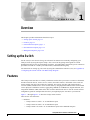
Overview
This chapter provides information about these topics:
•
Setting up the Switch, page 1-1
•
Features, page 1-1
•
Front-Panel Description, page 1-3
•
Rear-Panel Description, page 1-21
•
Management Options, page 1-24
Setting up the Switch
See the Catalyst 2950 Switch Getting Started Guide for instructions on initially configuring your
Catalyst switch by using the Express Setup. Also covered in the getting started guide are switch
management options, basic rack-mounting procedures, port and module connections, power connection
procedures for both AC- and DC-powered switches, and troubleshooting help.
For instructions on setting up your switch by using the command-line interface (CLI), see Appendix D,
“Configuring the Switch with the CLI-Based Setup Program.”
Features
The Catalyst 2950 switches are a family of Ethernet switches that you can use to connect workstations
and other network devices, such as servers, routers, and other switches. All models of the switch are
cluster-capable, but only some models are stackable. You can use switches with gigabit interface
converter (GBIC) module slots to create switch stacks by using Gigastack GBICs. Some switch models
can be deployed as backbone switches, aggregating 10BASE-T, 100BASE-TX, Gigabit Ethernet, and
Long-Reach Ethernet (LRE) traffic from other switches and network devices. See the switch software
configuration guide for examples that show how you might deploy the switches in your network.
Figure 1-1 through Figure 1-12 show the Catalyst 2950 switches.
These are the switch features:
•
Hardware
– Catalyst 2950-12 switch—12 10/100 Ethernet ports
– Catalyst 2950-24 switch—24 10/100 Ethernet ports
– Catalyst 2950C-24 switch—24 10/100 Ethernet ports and 2 100BASE-FX ports
Catalyst 2950 Switch Hardware Installation Guide
OL-6156-01
1-1
Chapter 1
Overview
Features
– Catalyst 2950G-12-EI—12 10/100 Ethernet ports and 2 GBIC module slots
– Catalyst 2950G-24-EI—24 10/100 Ethernet ports and 2 GBIC module slots
– Catalyst 2950G-24-EI-DC—24 10/100 Ethernet ports and 2 GBIC module slots with
DC-input power
– Catalyst 2950G-48-EI—48 10/100 Ethernet ports and 2 GBIC module slots
– Catalyst 2950ST-8 LRE switch—8 LRE ports, 2 10/100/1000 Ethernet ports, and
2 small-form-factor pluggable (SFP) module slots. (Two of the four uplink ports are active at
one time.)
– Catalyst 2950ST-24 LRE switch—24 LRE ports, 2 10/100/1000 Ethernet ports, and
2 SFP module slots. (Two of the four uplink ports are active at one time.)
– Catalyst 2950ST-24 LRE 997 switch—24 LRE ports, 2 10/100/1000 Ethernet ports, and
2 SFP module slots with DC-input power. (Two of the four uplink ports are active at one time.)
Note
See the Catalyst 2950 LRE switch release notes for a list of supported SFP modules for the
Catalyst 2950 LRE switches.
– Catalyst 2950SX-24 switch—24 10/100 Ethernet ports and 2 1000BASE-SX ports
– Catalyst 2950T-24 switch—24 10/100 Ethernet ports and 2 10/100/1000 Ethernet ports
– Catalyst 2950SX-48-SI switch—48 10/100 Ethernet ports and 2 1000BASE-SX ports
– Catalyst 2950T-48-SI switch—48 10/100 Ethernet ports and 2 10/100/1000 Ethernet ports
– On Catalyst 2950G-12-EI, 2950G-24-EI, 2950G-24-EI-DC, and 2950G-48-EI switches,
support for these GBIC modules:
1000BASE-SX GBIC
1000BASE-LX/LH GBIC
1000BASE-ZX GBIC
1000BASE-T GBIC (model WS-5483)
Coarse Wave Division Multiplexer (CWDM) fiber-optic GBIC
GigaStack GBIC
•
Configuration
– For 10/100 ports, autonegotiates the speed and duplex settings
– For 10/100/1000 ports on the Catalyst 2950T-24 switch, autonegotiates the speed and supports
only full-duplex mode
– For 10/100/1000 ports on the Catalyst 2950T-48-SI and 2950 LRE switches, autonegotiates the
speed and duplex setting when operating at 10 or 100 Mbps. When the switch is running at 1000
Mbps, it supports only full-duplex mode.
– For 100BASE-FX ports, supports only 100-Mbps and full-duplex settings
– For 1000BASE-SX ports, supports only 1000-Mbps and full-duplex settings
– Supports 8192 MAC addresses
– Checks for errors on a received packet, determines the destination port, stores the packet in
shared memory, and then forwards the packet to the destination port
Catalyst 2950 Switch Hardware Installation Guide
1-2
OL-6156-01
Chapter 1
Overview
Front-Panel Description
Power redundancy
•
– Connection for an optional Cisco RPS 300 redundant power system (RPS) that uses AC input
and supplies DC output to the switch
– Connection for an optional Cisco RPS 675 that uses AC input and supplies DC output to the
switch
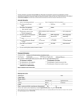
Certain Cisco LRE customer premises equipment (CPE) devices are not supported by certain Catalyst
2950 LRE switches. In Table 1-1, Yes means that the CPE is supported by the switch; No means that the
CPE is not supported by the switch.
Table 1-1
LRE Switch and CPE Compatibility Matrix
LRE Devices
Catalyst 2950ST-8 LRE
Catalyst 2950ST-24 LRE
Catalyst 2950ST-24 LRE 997
Cisco 575 LRE
CPE
Yes
Yes
No
Cisco 576 LRE 997 No
CPE
No
Yes
Cisco 585 LRE
CPE
Yes
No
Yes
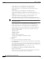
Front-Panel Description
The switch front panel contains the ports, the LEDs, and the Mode button.
Other than the Catalyst 2950ST-24 LRE 997 switch, the front panel of the Catalyst 2950 LRE switches
also contain the console port and AC power connector. On the Catalyst 2950ST-24 LRE 997 switch, the
front panel contains a DC power connector (also referred to as the terminal block header), a DC ground
lug, and an RJ-45 console port.
For more information about the power connectors on the LRE switches, see the “Power Connectors”
section on page 1-22. For more information on the console port on these switches, see the “Console Port”
section on page 1-24.
Figure 1-1 to Figure 1-12 show the switches.
SYST
RPS
STAT
UTIL DUPLX
MODE
SPEED
1x
2x
Catalyst 2950-12 Switch
3x
4x
5x
6x
7x
8x
9x
10x
10Base-T
11x
/ 100Base-
TX
12x
Catalyst 295
0 SERIES
45568
Figure 1-1
10/100 ports
Catalyst 2950 Switch Hardware Installation Guide
OL-6156-01
1-3
Chapter 1
Overview
Front-Panel Description
SYST
1
RPS
STAT
UTIL DUPLX
2
Catalyst 2950-24 Switch
3
4x
5x
6x
SPEED
7x
8x
9x
MODE
10Base-T
10x
/ 100Base-
TX
11x
12x
13x
14x
15x
16x
17x
18x
19x
20x
Catalyst 295
21x
0 SERIES
22x
23x
45567
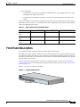
Figure 1-2
24x
10/100 ports
SYST
1x
RPS
STAT
UTIL DUPLX
2x
Catalyst 2950C-24 Switch
3x
4x
5x
6x
SPEED
7x
8x
9x
MODE
10BASE-T
10x
/ 100BASE
-TX
11x
12x
13x
14x
15x
16x
17x
18x
19x
20x
Catalyst 295
21x
0 SERIES
22x
23x
100BASE
45570
Figure 1-3
-FX
24x
25
26
10/100 ports
100BASE-FX ports
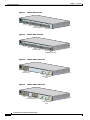
Figure 1-4
1
SYST
2
3
4
1X
5
Catalyst 2950G-12-EI Switch
6
RPS
STAT
UTIL DUPLX
7
8
9
10
11
12
SPEED
11X
2X
12X
1
Catalyst 295
0 SERIES
60978
MODE
2
10/100 ports
GBIC module
slots
1
SYST
1X
RPS
STAT
UTIL DUPLX
SPEED
2
3
4
5
Catalyst 2950G-24-EI Switch
6
7
8
9
10
11
12
13
11X
13X
14
15
16
17
MODE
2X
18
19
20
21
22
23
24
23X
12X
14X
1
Catalyst 295
0 SERIES
60977
Figure 1-5
24X
2
10/100 ports
GBIC module
slots
Catalyst 2950 Switch Hardware Installation Guide
1-4
OL-6156-01
Chapter 1
Overview
Front-Panel Description
1
SYST
2
3
4
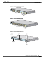
Catalyst 2950G-24-EI-DC Switch
5
1X
6
7
RPS
STAT
UTIL DUPLX
8
9
10
11
12
SPEED
13
11X
14
15
16
13X
17
18
MODE
19
20
21
2X
22
23
60977
Figure 1-6
24
23X
12X
Catalyst 295
14X
0 SERIES
1
24X
2
10/100 ports
GBIC module
slots
1
2
SYST
RPS
3
1X
4
5
Catalyst 2950G-48-EI Switch
6
7
8
9
STAT
10
11
UTIL
12
13
14
15
DUPLX
16
17
SPEED
MODE
15X
17X
16X
18X
2X
18
19
20
21
22
23
24
25
26
27
28
29
30
31
65507
Figure 1-7
32
33
31X
33X
32X
34X
34
35
36
37
38
39
40
41
42
43
44
45
46
47
Catalyst 295
0 SERIES
48
47X
1
48X
2
10/100 ports
GBIC module
slots
Figure 1-8
Catalyst 2950ST-8 LRE Switch
Power
connector
LRE
port
1
2
3
SYST
RPS
RATING
100-127
/200-240V~
1.0A/0.5
A 50-60HZ
CONSOLE
4
5
6
7
SFP
ports
8
STAT
SPEED
MODE
Catalyst
2950 SERIE
S
LRE
2
1
2
Console
port
81185
1
10/100/1000
ports
Catalyst 2950 Switch Hardware Installation Guide
OL-6156-01
1-5
Chapter 1
Overview
Front-Panel Description
Figure 1-9
Catalyst 2950ST-24 LRE Switch
Power
connector
LRE
port
1
2
3
4
5
SYST
6
7
CONSOLE
RPS
RATING
100-127
/200-240V~
1.0A/0.5
A 50-60HZ
8
9
SFP
ports
10 11
12
STAT
SPEED
MODE
13 14
15 16
17 18
19 20
21 22
23 24
Catalyst
2950 SERIE
S
LRE
1
81184
2
1
2
Console
port
10/100/1000
ports
Figure 1-10 Catalyst 2950ST-24 LRE 997 Switch
Power
connector
SFP
ports
LRE
port
SYST
RPS
CONSO
1
LE
+
2
3
STAT
-
-
+
A
INPUT
: 36 CURRENT
4
5
SPEED
6
7
8
B
72 V
:2-1
A
9
10 11
12
MODE
Console
port
Catalys
t 2950 SERIE
S
LRE 997
1
2
1
2
DC ground lug
89363
13 14
15 16
17 18
19 20
21 22
23 24
DC ground lug
10/100/1000
ports
SYST
RPS
STAT
UTIL DUPLX
MODE
SPEED
1x
2x
3x
4x
5x
6x
7x
8x
9x
10x
10BASE-T
11x
/ 100BASE
-TX
12x
13x
14x
15x
16x
17x
18x
19x
20x
Catalyst 295
21x
0 SERIES
22x
23x
24x
1000BAS
74516
Figure 1-11 Catalyst 2950SX-24 Switch
E-SX
25
26
10/100 ports
1000BASE-SX ports
Catalyst 2950 Switch Hardware Installation Guide
1-6
OL-6156-01
Chapter 1
Overview
Front-Panel Description
SYST
1x
RPS
STAT
UTIL DUPLX
2x
3x
4x
5x
6x
SPEED
7x
8x
9x
MODE
10Base-T
10x
/ 100Base-
TX
11x
12x
13x
14x
15x
16x
17x
18x
19x
Catalyst 295
20x
0 SERIES
21x
22x
23x
24x
10/100/1
47337
Figure 1-12 Catalyst 2950T-24 Switch
00Base-T
1
2
10/100 ports
10/100/1000 ports
1
SYST
RPS
2
3
4
1X
5
6
7
8
STAT
9
10
11
UTIL
12
13
14
15
DUPLX
16
17
SPEED
MODE
97630
Figure 1-13 Catalyst 2950SX-48-SI Switch
15X
17X
16X
18X
18
19
20
21
22
23
24
25
2X
26
27
28
29
30
31
32
33
31X
33X
32X
34X
34
35
36
37
38
39
40
41
42
43
44
45
46
47
Catalyst 2950
48
SERIES
47X
1
2
48X
10/100 ports
1000BASE-SX ports
Figure 1-14 Catalyst 2950T-48-SI Switch
RPS
1X
STAT
UTIL
DUPLX
2
3
4
5
6
7
8
9
10
11
12
13
14
15
16
17
SPEED
MODE
15X
17X
16X
18X
2X
18
19
20
21
22
23
24
25
26
27
28
29
30
31
97626
1
SYST
32
33
31X
33X
32X
34X
34
35
36
37
38
39
40
41
42
43
44
45
46
47
Catalyst 2950
48
SERIES
47X
1
2
48X
10/100 ports
10/100/1000 ports
10/100 Ports
The 10/100 ports use RJ-45 connectors and twisted-pair cabling. The ports can connect to these devices:
•
10BASE-T devices, such as workstations and hubs, through standard RJ-45 connectors and two
twisted-pair cabling. You can use Category 3, 4, or 5 cabling.
•
100BASE-TX devices, such as high-speed workstations, servers, hubs, routers, and other switches,
through standard RJ-45 connectors and two or four twisted-pair, Category 5 cabling.
Catalyst 2950 Switch Hardware Installation Guide
OL-6156-01
1-7
Chapter 1
Overview
Front-Panel Description
Note
When connecting the switch to workstations, servers, and routers, be sure that the cable is a twisted-pair
straight-through cable. When connecting the switch to hubs or other switches, use a twisted-pair
crossover cable. Pinouts for the cables are described in Appendix B, “Connectors and Cables.”
For information on how to identify a crossover cable, go to the “Identifying a Crossover Cable” section
on page B-5.
The 10/100 ports can be explicitly set to operate in any combination of half duplex, full duplex, 10 Mbps,
or 100 Mbps. They can also be set for speed and duplex autonegotiation, compliant with IEEE 802.3U.
In all cases, the cable length from a switch to an attached device cannot exceed 328 feet (100 meters).
When set for autonegotiation, a port senses the speed and duplex settings of the attached device and
advertises its own capabilities. If the attached device supports autonegotiation, the port negotiates the
best connection (that is, the fastest line speed that both devices support and full-duplex transmission, if
the attached device supports it) and configures itself accordingly.
10/100/1000 Ports
The 10/100/1000 ports on Catalyst 2950T-24, Catalyst 2950T-48-SI, and Catalyst 2950 LRE switches
use RJ-45 connectors and twisted-pair cabling. The ports can connect to these devices:
•
10BASE-T devices, such as workstations and hubs, through standard RJ-45 connectors and two or
four twisted-pair, Category 5 cabling.
•
100BASE-TX devices, such as high-speed workstations, servers, hubs, routers, and other switches,
through standard RJ-45 connectors and two or four twisted-pair, Category 5 cabling.
•
1000BASE-T devices, such as high-speed workstations, servers, hubs, routers, and other switches,
through standard RJ-45 connectors and four twisted-pair, Category 5 cabling.
Note
When connecting the switch to a 1000BASE-T device, be sure to use a four twisted-pair, Category 5
cable.
Note
When connecting the switch to workstations, servers, and routers, be sure to use a twisted-pair
straight-through cable. When connecting the switch to hubs or other switches, use a twisted-pair
crossover cable. Pinouts for the cables are described in Appendix B, “Connectors and Cables.”
For information on how to identify a crossover cable, go to the “Identifying a Crossover Cable” section
on page B-5.
The 10/100/1000 ports on the Catalyst 2950T-24 switch can be explicitly set to operate at 10, 100, or
1000 Mbps, but only in full-duplex mode. The 10/100/1000 ports on the Catalyst 2950T-48-SI and
Catalyst 2950 LRE switches can be explicitly set to operate at 10 or 100 Mbps in full- or half-duplex
mode or at 1000 Mbps in full-duplex mode.
The 10/100/1000 ports can also be set for speed autonegotiation, compliant with IEEE 802.3AB. In all
cases, the cable length from a switch to an attached device cannot exceed 328 feet (100 meters).
Catalyst 2950 Switch Hardware Installation Guide
1-8
OL-6156-01
Chapter 1
Overview
Front-Panel Description
Note
On the Catalyst 2950 LRE switches, the four input uplink ports are bundled as two logical ports, each
consisting of a copper 10/100/1000 port and a fiber-optic SFP module slot, respectively.
Within each logical port, you can use only the copper or the fiber-optic port at one time. If a Catalyst
2950 LRE switch senses more than two connections for both logical ports, the switch chooses the
fiber-optic connections over the copper connections in default operation.
See the “SFP Module Slots” section on page 1-11 for more information on LRE uplink logical ports.
100BASE-FX and 1000BASE-SX Ports
The 100BASE-FX and 1000BASE-SX ports both use 50/125- or 62.5/125-micron multimode fiber-optic
cabling. The 100BASE-FX ports operate only at 100 Mbps in full-duplex mode, and the 1000BASE-SX
ports operate only at 1000 Mbps in full-duplex mode.
In full-duplex mode, the cable length from a 100BASE-FX port on a switch to an attached device cannot
exceed 6562 feet (2 kilometers). The cable length from a 1000BASE-SX port on a switch to an attached
device cannot exceed 1804 feet (550 meters).
You can connect a 100BASE-FX or 1000BASE-SX port to an SC or ST port on a target device by using
one of the MT-RJ fiber-optic patch cables listed in Table 2-1 on page 2-29. Use the Cisco part numbers
in Table 2-1 to order the patch cables that you need.
LRE Port
The LRE port (shown in Figure 1-8) uses one RJ-21 connector to connect up to 24 Cisco LRE CPE
devices through structured or unstructured wiring, such as existing telephone lines. The link between the
LRE switch port and each CPE device can reach speeds of up to 15 Mbps (full duplex) over distances of
up to 4921 feet (1500 meters).
Certain Catalyst 2950 LRE switches support certain Cisco LRE CPE devices. Table 1-1 on page 1-3
shows which LRE switches support which CPE devices.
You can connect the Cisco 575 LRE CPE and Cisco 585 LRE CPE devices to LRE ports on the same
Catalyst 2950ST-8 LRE or 2950ST-24 LRE switch. You can connect the Cisco 576 LRE CPE 997 device
only to LRE ports on a Catalyst 2950ST-24 LRE 997 switch. You can hot swap the CPE devices without
powering down the switch or disrupting the other switch ports.
The default mode for each LRE port is speed autosensing and half-duplex operation. For information
about configuring the LRE ports, see the switch software configuration guide.
If telephone services, such as voice or an Integrated Services Digital Network (ISDN), use the same
cabling as LRE traffic, the LRE port must be connected to the patch panel through a plain old telephone
service (POTS) splitter. The splitter routes LRE data (high-frequency) and voice (low-frequency) traffic
from the telephone line to the switch and private branch exchange (PBX) switch or public switched
telephone network (PSTN).
If the other telephone services are connected through a PBX switch, a non-homologated POTS splitter,
such as the Cisco LRE 48 POTS Splitter, can be used. The PBX routes voice traffic to private telephone
networks and the PSTN. For more information about the Cisco LRE 48 POTS Splitter (PS-1M-LRE-48),
see the Installation and Warranty Notes for the Cisco LRE 48 POTS Splitter.
Catalyst 2950 Switch Hardware Installation Guide
OL-6156-01
1-9
Chapter 1
Overview
Front-Panel Description
For limitations and restrictions when you use a POTS splitter with the Catalyst 2950 LRE switches and
Cisco LRE CPE, see the “Limitations and Restrictions with POTS Splitters” section on page 2-31.
If the installation does not have a PBX, a certified, homologated POTS splitter is required to connect
directly to the PSTN. For more information about homologated POTS splitters, contact your Cisco sales
representative.
If a connection to a telephone network is not required, a splitter is not needed, and the switch can connect
directly to the patch panel.
For more information about the Cisco LRE CPE devices, see the Cisco LRE CPE Hardware Installation
Guide.
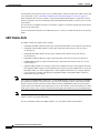
GBIC Module Ports
The GBIC module slots support these modules:
•
1000BASE-SX GBIC module for fiber-optic connections that cannot exceed 1804 feet (550 meters).
•
1000BASE-LX/LH GBIC module for fiber-optic connections that cannot exceed 32,810 feet
(10 kilometers).
•
1000BASE-ZX GBIC module for fiber-optic connections that cannot exceed 328,100 feet
(100 kilometers).
•
1000BASE-T GBIC module for copper connections that cannot exceed 328 feet (100 meters).
•
CWDM GBIC module for single-mode fiber-optic connections that cannot exceed 393,719 feet
(120 kilometers).
•
GigaStack GBIC module for creating a 1-Gbps stack configuration of up to nine supported switches.
The GigaStack GBIC supports one full-duplex link (in a point-to-point configuration) or up to nine
half-duplex links (in a stack configuration) to other Gigabit Ethernet devices. Using the required
Cisco proprietary signaling and cabling, the GigaStack GBIC-to-GigaStack GBIC connection
cannot exceed 3 feet (1 meter).
Note
Cisco-approved CWDM GBIC modules have a serial EEPROM that contains the module serial number,
the vendor name and ID, a unique security code, and cyclic redundancy check (CRC). When a GBIC
module is inserted in the switch, the switch software reads the EEPROM to check the serial number,
vendor name, and vendor ID and recomputes the security code and CRC. If the serial number, the vendor
name or ID, security code, or CRC is invalid, the switch places the interface in an error-disabled state.
Note
If you are using a non-Cisco approved CWDM GBIC module, remove the module from the switch, and
replace it with a Cisco-approved module.
For more information about these GBIC modules, see your GBIC module documentation.
Catalyst 2950 Switch Hardware Installation Guide
1-10
OL-6156-01
Chapter 1
Overview
Front-Panel Description
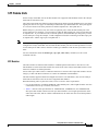
SFP Module Slots
On the Catalyst 2950 LRE switch, the SFP module slots support the SFP modules listed in the Catalyst
2950 LRE switch release notes.
The Catalyst 2950 LRE switch has four physical input ports that are logically bundled as two ports. Each
logical port consists of a copper 10/100/1000 port and a fiber-optic SFP module slot. These ports appear
as a vertical column on the front panel and are labeled Uplink Port 1 and Uplink Port 2.
Within each port, you can use only one of the two physical ports, either the SFP module port or the
10/100/1000 port. For example, you can connect to either the SFP module port or the 10/100/1000 port
on Uplink Port 1. If you connect to both, in default operation, the SFP module port has priority over the
10/100/1000 port. Using this example, a valid configuration would be connecting to the fiber-optic port
on Uplink Port 1 and the copper port on Uplink Port 2.
Note
By using the media-type {sfp | rj45 | auto-select} interface configuration command at the CLI, you can
configure the Catalyst 2950 LRE switch so that the SFP module port does not take precedence over the
10/100/1000 port. In that scenario, whichever media type establishes a link first has precedence over the
other.
For more information about the media-type {sfp | rj45 | auto-select} command, see the switch
command reference.
SFP Modules
The LRE switches use Ethernet SFP modules to establish uplink connections to other devices. The
SFP modules are inserted into SFP module slots on the front of the Catalyst 2950 LRE switches. These
transceiver modules are field-replaceable.
You use fiber-optic cables with LC or MT-RJ connectors to connect to fiber-optic SFP modules. You use
Category 5 cable with RJ-45 connectors to connect to 1000BASE-T SFP modules.
The SFP modules support nominal wavelengths from 850 to 1550 nanometers (nm). See the Catalyst
2950 LRE switch release notes for the list of supported SFP modules.
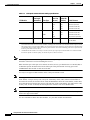
When determining where to place the switch, be sure to observe these requirements:
•
For 10/100/1000 ports, including 1000BASE-T SFP module ports, cable lengths from the switch to
connected devices are up to 328 feet (100 meters).
•
Table 1-2 lists the cable specifications for 1000BASE-SX, 1000BASE-LX, and 1000BASE-ZX
fiber-optic SFP module connections. Each port must match the wave-length specifications on the
other end of the cable, and for reliable communications, the cable must not exceed the stipulated
cable length.
Catalyst 2950 Switch Hardware Installation Guide
OL-6156-01
1-11
Chapter 1
Overview
Front-Panel Description
Table 1-2
Fiber-Optic SFP Module Port Cabling Specifications
Core Size
(micron)
Modal
Bandwidth
(MHz/km)
Cable Distance
MMF
62.5
62.5
50
50
160
200
400
500
722 feet (220 m)
902 feet (275 m)
1640 feet (500 m)
1804 feet (550 m)
MMF1
62.5
50
50
9/10
500
400
500
—
1804 feet (550 m)
1804 feet (550 m)
1804 feet (550 m)
32,810 feet (10 km)
9/10
—
43.4 to 62 miles (70
to 100 km)2
SFP Module
Wavelength
(nanometers)
Fiber Type
1000BASE-SX
850
1000BASE-LX/LH
1300
SMF
1000BASE-ZX
1550
SMF
1. A mode-conditioning patch cord is required. Using an ordinary patch cord with MMF, 1000BASE-LX/LH SFP modules, and
a short link distance can cause transceiver saturation, resulting in an elevated bit error rate (BER). When using the LX/LH
SFP module with 62.5-micron diameter MMF, you must also install a mode-conditioning patch cord between the SFP module
and the MMF cable on both the sending and receiving ends of the link. The mode-conditioning patch cord is required for link
distances greater than 984 feet (300 m).
2. 1000BASE-ZX SFP modules can send up to 62 miles (100 km) by using dispersion-shifted SMF or low-attenuation SMF;
the distance depends on the fiber quality, the number of splices, and the connectors.
Note
When using shorter distances of single-mode fiber cable, you might need to insert an inline optical
attenuator in the link to avoid overloading the receiver.
When the fiber-optic cable span is less than15.43 miles (25 km), you should insert a 5-decibel (dB) or
10-dB inline optical attenuator between the fiber-optic cable plant and the receiving port on the
1000BASE-ZX SFP module at each end of the link.
Use only Cisco-approved SFP modules on the Catalyst 2950 LRE switch.
Note
Cisco-approved SFP modules have a serial EEPROM that contains the module serial number, the vendor
name and ID, a unique security code, and cyclic redundancy check (CRC). When an SFP module is
inserted in the switch, the switch software reads the EEPROM to check the serial number, vendor name,
and vendor ID and recomputes the security code and CRC. If the serial number, the vendor name or ID,
security code, or CRC is invalid, the switch places the interface in an error-disabled state.
Note
If you are using a non-Cisco approved SFP module, remove the module from the switch, and replace it
with a Cisco-approved module.
For more information about these SFP modules, see your SFP module documentation.
Catalyst 2950 Switch Hardware Installation Guide
1-12
OL-6156-01
Chapter 1
Overview
Front-Panel Description
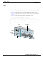
LEDs
You can use the LEDs to monitor switch activity and performance. The locations and numbers of the
LEDs vary among switch models. The location of the Mode button that you use to select the port mode
also varies by model. See these figures:
•
Figure 1-15 for the Catalyst 2950-12, 2950-24, 2950C-24, 2950SX-24, and 2950T-24 switches
•
Figure 1-16 for the Catalyst 2950G-12-EI, 2950G-24-EI, and 2950G-24-EI-DC switches
•
Figure 1-17 for the Catalyst 2950G-48-EI, Catalyst 2950SX-48-SI, and Catalyst 2950T-48-SI
switches
•
Figure 1-18 for the Catalyst 2950ST-8 LRE and 2950ST-24 LRE switches
•
Figure 1-19 for the Catalyst 2950ST-24 LRE 997 switches
All LEDs (except the utilization meter [UTIL]) are visible through the GUI management
applications—the Network Assistant application for multiple switches and the device manager for a
single switch. The switch software configuration guide describes how to use the command-line interface
(CLI) to configure and to monitor individual switches and switch clusters.
Figure 1-15 LEDs on Catalyst 2950-12, 2950-24, 2950C-24, 2950SX-24, and 2950T-24 Switches
RPS
LED
Port status
LEDs
System
LED
SYST
RPS
Port mode
LEDs
STAT
UTIL D
UPLX
SPEED
1x
2x
3x
4x
5x
6x
Mode button
52918
MODE
Catalyst 2950 Switch Hardware Installation Guide
OL-6156-01
1-13
Chapter 1
Overview
Front-Panel Description
Figure 1-16 LEDs on Catalyst 2950G-12-EI, 2950G-24-EI, and 2950G-24-EI-DC Switches
RPS
LED
Port status
LEDs
System
LED
1
SYST
2
3
4
5
1X
6
RPS
STAT
UTIL D
UPLX
8
9
10
11
12
SPEED
11X
MODE
2X
12X
Mode button
65395
Port mode
LEDs
7
Figure 1-17 LEDs on Catalyst 2950G-48-EI, 2950SX-48-SI, and 2950T-48-SI Switches
Port status
LEDs
System
LED
Port
mode
LEDs
1
SYST
RPS
1X
STAT
UTIL
DUPLX
2
3
4
5
6
7
8
9
10
11
12
13
14
15
16
SPEED
15X
MODE
2X
16X
Mode button
65508
RPS
LED
Catalyst 2950 Switch Hardware Installation Guide
1-14
OL-6156-01
Chapter 1
Overview
Front-Panel Description
Figure 1-18 LEDs on Catalyst 2950ST-8 LRE and 2950ST-24 LRE Switches
System
LED
Redundant
power
system
LED
Port status
LEDs
1
SYST
3
4
5
6
CONSO
7
LE
RPS
RATING
100-127/
200-240V
~
1.0A/0.5
A 50-60H
Z
2
8
STAT
SPEED
MODE
Speed
LED
81187
Mode button
STAT
LED
Figure 1-19 LEDs on Catalyst 2950ST-24 LRE 997 Switches
System
LED
Redundant
power
system
LED
Port status
LEDs
SYST
RPS
CONSO
LE
+
STAT
-
A
B
INPUT
: 36 72 V
CURREN
T :2
-1
-
+
SPEED
1
2
3
4
5
6
7
8
9
10 11
12
A
STAT
LED
Mode
button
Speed
LED
89364
MODE
Catalyst 2950 Switch Hardware Installation Guide
OL-6156-01
1-15
Chapter 1
Overview
Front-Panel Description
System LED
The system LED shows whether the system is receiving power and functioning properly. Table 1-3 lists
the LED colors and meanings.
Table 1-3
System LED
Color
System Status
Off
System is not powered up.
Green
System is operating normally.
Amber
System is receiving power but is not functioning properly.
For information about the system LED colors during the power-on self-test (POST), see the “Connecting
to a Power Source” section on page D-5.
RPS LED
The RPS LED shows the RPS status. Table 1-4 lists the LED colors and meanings.
Table 1-4
RPS LED
Color
RPS Status
Off
RPS is off or is not installed.
Solid green
RPS is connected and ready to provide back-up power.
Flashing green
RPS is connected but is unavailable because it is providing
power to another device (redundancy has been allocated to a
neighboring device).
Solid amber
RPS is in standby mode or in a fault condition. Press the
Standby/Active button on the RPS, and the LED should turn
green. If it does not, the RPS fan could have failed. Contact
Cisco Systems.
Flashing amber The internal power supply in a switch has failed, and the RPS
is providing power to the switch (redundancy has been
allocated to this device).
For more information about the Cisco RPS 300, see the Cisco RPS 300 Redundant Power System
Hardware Installation Guide.
For more information about the Cisco RPS 675, see the Cisco RPS 675 Redundant Power System
Hardware Installation Guide.
Port Mode and Port Status LEDs
To select or change the port mode, press the Mode button (see Figure 1-15 to Figure 1-18) to highlight
the mode that you want. Release the button to enable the highlighted mode.
Each port has a port status LED, also called a port LED. These LEDs, as a group or individually, display
information about the switch and the individual ports. The port modes (see Table 1-5) determine the type
of information displayed.
Catalyst 2950 Switch Hardware Installation Guide
1-16
OL-6156-01
Chapter 1
Overview
Front-Panel Description
Table 1-5
Port Mode LEDs
Mode LED
Port Mode
Description
STAT
Port status
The port status. This is the default mode.
Switch utilization
The bandwidth in use by the switch.
DUPLX
Port duplex mode
The port duplex mode: half duplex or full duplex.
SPEED
Port speed
The port operating speed: 10 or 100 Mbps for 10/100 ports
and 10, 100, or 1000 Mbps for 10/100/1000 ports.
UTIL
1
1. A Catalyst 2950 LRE switch does not have a UTIL or a DUPLX LED.
When you change the port mode, the meanings of the port LED colors change. Table 1-6 explains how
to interpret these colors for the non-LRE switches. Table 1-7 explains how to interpret the colors for the
LRE switches. The port LEDs are off when the MODE is set to SPEED.
Table 1-6
Meaning of Port LED Colors in Different Modes for Non-LRE Switches
Port Mode
Color
Meaning
STAT (port status)
Off
No link.
Solid green
Link present.
Flashing green Activity. Port is sending or receiving data.
Alternating
green-amber
Link fault. Error frames can affect connectivity, and errors such
as excessive collisions, CRC errors, and alignment and jabber
errors are monitored for a link-fault indication.
Solid amber
Port is not forwarding. Port was disabled by management, an
address violation, or Spanning Tree Protocol (STP).
Note
UTIL (utilization)
DUPLX
After a port is reconfigured, the port LED can remain
amber for up to 30 seconds while STP checks the switch
for possible loops.
Green
The current backplane utilization that is displayed over the
amber LED background on a logarithmic scale.
Amber
The maximum backplane utilization since the switch was
powered on.
Green and
amber
See Figure 1-20 to Figure 1-24 for details.
Off
Port is operating in half duplex.
(half or full duplex) Green
Note
If the current utilization exceeds the maximum
utilization, the maximum utilization is automatically
updated.
Port is operating in full duplex.
Catalyst 2950 Switch Hardware Installation Guide
OL-6156-01
1-17
Chapter 1
Overview
Front-Panel Description
Table 1-6
Meaning of Port LED Colors in Different Modes for Non-LRE Switches (continued)
Port Mode
Color
SPEED
10/100 ports
Meaning
Off
Port is operating at 10 Mbps.
Green
Port is operating at 100 Mbps.
10/100/1000 ports
Off
Port is operating at 10 Mbps.
Green
Port is operating at 100 Mbps.
Flashing green Port is operating at 1000 Mbps.
1000BASE-X GBIC module ports
Table 1-7
Off
Port is not operating.
Green
Port is operating at 1000 Mbps.
Meaning of Port LED Colors in Different Modes for the LRE Switches
Port Mode
Color
Meaning
STAT (port status)
Off
No link.
Solid green
Link present.
Note
The LRE port LED turns green approximately 30 seconds
after the LRE port detects a connection to an LRE CPE.
Flashing green Activity. Port is sending or receiving data.
Alternating
green-amber
Link fault. Error frames can affect connectivity, and errors such
as excessive collisions, CRC errors, and alignment and jabber
errors are monitored for a link-fault indication.
Solid amber
A link is established on a nonassigned LRE profile, or a port is
not forwarding.
If a port is not forwarding, it was disabled by management, an
address violation, or STP.
Note
DUPLX
Off
(half or full duplex) Green
After a port is reconfigured, the port LED can remain
amber for up to 30 seconds while STP checks the switch
for possible loops.
Port is operating in half duplex.
Port is operating in full duplex.
Catalyst 2950 Switch Hardware Installation Guide
1-18
OL-6156-01
Chapter 1
Overview
Front-Panel Description
Table 1-7
Meaning of Port LED Colors in Different Modes for the LRE Switches (continued)
Port Mode
Color
Meaning
SPEED
10/100/1000 ports1 2
Off
Port is operating at 10 Mbps.
Green
Port is operating at 100 Mbps.
Flashing green Port is operating at 1000 Mbps.
SFP modules1 2
Off
Port is operating at 10 Mbps
Green
Port is operating at 100 Mbps
Flashing green Port is operating at 1000 Mbps
1. On an LRE switch, the LEDs for Uplink Port 1 and Uplink Port 2 correspond either to the SFP module port or to the
10/100/1000 port, depending on which is active.
2. If an LRE switch senses connections to both ports, by default, the switch chooses the fiber-optic connection over the copper
connection.
For more information about GBIC LEDs, see your GBIC module documentation.
Figure 1-20 to Figure 1-24 show the bandwidth utilization percentages displayed by the right-most
LEDs.
Note
The Catalyst 2950 LRE switch LEDs do not give utilization status.
If all LEDs on a Catalyst 2950-12, 2950-24, 2950C-24, 2950SX-24, or 2950T-24 switch are green (no
amber showing), the switch is using 50 percent or more of the total bandwidth. If the far-right LED is
off, the switch is using more than 25 but less than 50 percent of the total bandwidth, and so on. If only
the far-left LED is green, the switch is using less than 0.0488 percent of the total bandwidth. (See
Figure 1-20 and Figure 1-21.)
Figure 1-20 Bandwidth Utilization on Catalyst 2950-12 Switches
Catalyst 2950 SERIES
10Base-T / 100Base-TX
1x
STAT
2x
3x
4x
5x
6x
7x
RPS
8x
9x
10x
11x
12x
47267
SYST
UTIL DUPLX SPEED
MODE
0–0.0487%+
6.25–12.4%+
12.5–24%+
25–49%+
50%+
Catalyst 2950 Switch Hardware Installation Guide
OL-6156-01
1-19
Chapter 1
Overview
Front-Panel Description
Figure 1-21 Bandwidth Utilization on Catalyst 2950-24, 2950C-24, 2950SX-24, and 2950T-24 Switches
Catalyst 2950 SERIES
10Base-T / 100Base-TX
1x
3x
4x
5x
6x
7x
8x
9x
10x
11x
12x
13x
100Base-FX
14x
15x
16x
17x
18x
19x
20x
21x
22x
23x
24x
25x
RPS
26x
74725
SYST
STAT
2x
UTIL DUPLX SPEED
MODE
0–0.0487%+
6.25–12.4%+
12.5–24%+
25–49%+
50%+
If all LEDs on a Catalyst 2950G-12-EI switch are green (no amber showing), the switch is using 50
percent or more of the total bandwidth. If the LED for GBIC module slot 2 is off, the switch is using
more than 25 but less than 50 percent of the total bandwidth. If LEDs for both GBIC module slots are
off, the switch is using less than 25 percent of the total bandwidth, and so on. (See Figure 1-22.)
Figure 1-22 Bandwidth Utilization on Catalyst 2950G-12-EI Switches
1
2
3
4
5
6
7
8
9
10
Catalyst 2950
11 12
11X
1
STAT
2
RPS
UTIL
DUPLX
SPEED
2X
12X
MODE
65397
1X
SYST
< 25% +
25% – 49% +
50% +
If all LEDs on a Catalyst 2950G-24-EI or 2950G-24-EI-DC switch are green (no amber showing), the
switch is using 50 percent or more of the total bandwidth. If the LED for GBIC module slot 2 is off, the
switch is using more than 25 but less than 50 percent of the total bandwidth. If LEDs for both GBIC
module slots are off, the switch is using less than 25 percent of the total bandwidth, and so on. (See
Figure 1-23.)
Figure 1-23 Bandwidth Utilization on Catalyst 2950G-24-EI and 2950G-24-EI-DC Switches
2
3
4
5
6
7
8
9
10
11 12
13 14
11X
15 16
17 18
19 20
13X
21 22
Catalyst 2950
23 24
15X
1
STAT
RPS
UTIL
DUPLX
SPEED
2X
12X
14X
MODE
16X
2
65396
1
1X
SYST
< 25% +
25% – 49% +
50% +
If all LEDs on a Catalyst 2950G-48-EI, 2950SX-48-SI, or 2950T-48-SI switch are green, the switch is
using 50 percent or more of the total bandwidth. If the LED for GBIC module slot 2 is off, the switch is
using more than 25 but less than 50 percent of the total bandwidth. If LEDs for both GBIC module slots
are off, the switch is using less than 25 percent of the total bandwidth, and so on. (See Figure 1-24.)
Catalyst 2950 Switch Hardware Installation Guide
1-20
OL-6156-01
Chapter 1
Overview
Rear-Panel Description
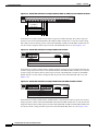
Figure 1-24 Bandwidth Utilization on Catalyst 2950G-48-EI, 2950SX-48-SI, and 2950T-48-SI Switches
Catalyst 2950
1
2
3
24
5
6
7
8
9
10
11 12
13 14
15 16
17 18
19 20
21 22
23 24
25 26
27 28
29 31
31 32
33 34
35 36
37 38
39 40
41 42
43 44
45 46
47 48
1X
15X
17X
31X
33X
47X
2X
16X
18X
32X
34X
48X
2
MODE
65510
1
SYST
RPS
STAT
UTIL
DUPLX
SPEED
< 25% +
25% – 49% +
50% +
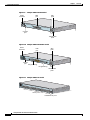
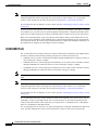
Rear-Panel Description
Other than the Catalyst 2950G-24-EI-DC switch and the Catalyst 2950 LRE switches, the rear panel of
a Catalyst 2950 switch has an AC power connector, an RPS connector, and an RJ-45 console port. (See
Figure 1-25 and Figure 1-26.)
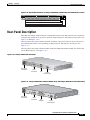
The rear panel of the Catalyst 2950G-24-EI-DC switch has a DC power connector (also referred to as
the terminal block header), a DC ground lug, an RPS connector, and an RJ-45 console port. (See
Figure 1-27.)
The rear panel of the Catalyst 2950ST-8 LRE, 2950ST-24 LRE, and 2950ST-24 LRE 997 switches has
only an RPS connector. (See Figure 1-28.)
Figure 1-25 Catalyst 2950 Switch Rear Panel
DC INPUT
FO
POWE R REMOTE
SPECIF R SUPPLY
IED IN
+12V @4MANUAL.
.5A
45585
RATING
100-127V~
@ 1A
200-240V~
@0.5A
50-60Hz
CONSOLE
AC power
connector
RPS
connector
Fan
RJ-45
console port
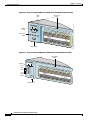
Figure 1-26 Catalyst 2950G-48-EI, Catalyst 2950SX-48-SI, and Catalyst 2950T-48-SI Switch Rear Panel
DC INPUT
FO
POWE R REMOTE
SPECIF R SUPPLY
IED IN
+12V @4MANUAL.
.5A
65511
RATING
100-127V~
@ 1A
200-240V~
@0.5A
50-60Hz
CONSOLE
AC power
connector
RPS
connector
Fan
exhaust
RJ-45
console port
Catalyst 2950 Switch Hardware Installation Guide
OL-6156-01
1-21
Chapter 1
Overview
Rear-Panel Description
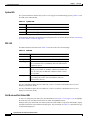
Figure 1-27 Catalyst 2950G-24-EI-DC Switch Rear Panel
A
B
DC INPUT
FO
POWE R REMOTE
SPECIF R SUPPLY
IED IN
+12V @4MANUAL.
.5A
65291
36 - 72V
1 - 0.5A
CONSOLE
DC power
connector
RPS
connector
Fan
RJ-45
DC
console ground
port
lug
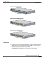
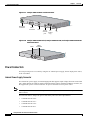
Figure 1-28 Catalyst 2950ST-8 LRE Switch, Catalyst 2950ST-24 LRE, and Catalyst 2950ST-24 LRE 997
Switch Rear Panel
RPS
connector
81225
Fans
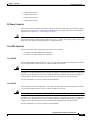
Power Connectors
You can provide power to a switch by using the AC internal power supply, the DC-input power source,
or the Cisco RPS.
Internal Power Supply Connector
The internal AC power supply is an autoranging unit that supports input voltages between 100 and 240
VAC. Other than for the Catalyst 2950G-24-EI-DC and the Catalyst 2950ST-24 LRE 997 switches, use
the supplied AC power cord to connect the AC power connector to an AC power outlet.
Note
The AC power connector is on the front panel of the Catalyst 2950ST-8 LRE and Catalyst 2950ST-24
LRE switches.
You can order these L-shaped AC power cords from your Cisco sales representative:
•
CAB-NP1200-AC-AR=
•
CAB-NP1200-AC-AU=
•
CAB-NP1200-AC-CH=
•
CAB-NP1200-AC-EU=
Catalyst 2950 Switch Hardware Installation Guide
1-22
OL-6156-01
Chapter 1
Overview
Rear-Panel Description
•
CAB-NP1200-AC-IT=
•
CAB-NP1200-AC-JP=
•
CAB-NP1200-AC-UK=
•
CAB-NP1200-AC-US=
DC Power Connector
The Catalyst 2950G-24-EI-DC and Catalyst 2950ST-24 LRE 997 switches have an internal DC-power
converter. It has dual feeds (A and B) that are diode-OR-ed into a single power block. For installation
instructions, see Appendix C, “Connecting to DC Power.”
Caution
You must connect the Catalyst 2950G-24-EI-DC and 2950ST-24 LRE 997 switches only to a DC-input
power source that has an input supply voltage from –36 to –72 VDC. If the supply voltage is not in this
range, the switch might not operate properly or might be damaged.
Cisco RPS Connector
Specific Cisco RPS models support specific Catalyst 2950 switches:
•
Cisco RPS 300 (model PWR300-AC-RPS-N1)
•
Cisco RPS 675 (model PWR675-AC-RPS-N1=)
Cisco RPS 300
The Cisco RPS 300 has two output levels: –48 V and 12 V with a total maximum output power of 300 W.
Use the supplied RPS connector cable to connect the RPS to the switch.
Warning
Attach only the Cisco RPS 300 (model PWR300-AC-RPS-N1) to the RPS receptacle. Statement 100B
The RPS is a 300-W redundant power system that can support six external network devices and provides
DC power to one failed device at a time. It automatically senses when the internal power supply of a
connected device fails and provides power to that device, preventing loss of network traffic.
For more information, see the Cisco RPS 300 documentation.
Cisco RPS 675
The Cisco RPS 675 has two output levels: –48 V and 12 V with a total maximum output power of 675 W.
Use the supplied RPS connector cable to connect the RPS to the switch.
Warning
Attach only the Cisco RPS 675 (model PWR675-AC-RPS-N1=) to the RPS receptacle. Statement 100C
The RPS is a 675-W redundant power system that can support six external network devices and provides
DC power to one failed device at a time. It automatically senses when the internal power supply of a
connected device fails and provides power to that device, preventing loss of network traffic.
For more information, see the Cisco RPS 675 documentation.
Catalyst 2950 Switch Hardware Installation Guide
OL-6156-01
1-23
Chapter 1
Overview
Management Options
Console Port
You can connect a switch to a PC through the console port and the supplied RJ-45-to-DB-9 adapter cable.
If you want to connect a switch to a terminal, you need to provide an RJ-45-to-DB-25 female DTE
adapter. You can order a kit (part number ACS-DSBUASYN=) with that adapter from Cisco. For
console-port and adapter-pinout information, see the “Cable and Adapter Specifications” section on
page B-6.
Management Options
Catalyst 2950 switches offer these management options:
•
Network Assistant
•
The Network Assistant is a GUI-based application that you can install and run on your desktop; you
do not need a web browser to run it. You can use Network Assistant to manage and monitor switch
clusters or standalone devices. For more information, see the Getting Started with Cisco Network
Assistant guide and the Network Assistant online help.
•
Device Manager
You can use the device manager, which is in the switch memory, to manage individual and
standalone switches. Use the device manager to perform basic switch configuration and monitoring.
You can access the device manager from anywhere in your network through a web browser.
To launch the Device Manager, enter the switch IP address in the web browser, and press Enter. The
device manager page appears.
Refer to the device manager online help for more information.
•
Cisco IOS CLI.
You can manage switches by using command-line entries. To access the CLI, connect a PC or a
terminal directly to the console port on the switch. If the switch is attached to your network, you can
use a Telnet connection to manage the switch from a remote location. For more information, see the
switch command reference.
For setup instructions that use the CLI, go to Appendix D, “Configuring the Switch with the
CLI-Based Setup Program.”
•
CiscoView application
You can use the CiscoView device-management application to set configuration parameters and to
view switch status and performance information. This application, which you purchase separately,
can be a standalone application or part of an Simple Network Management Protocol (SNMP)
network-management platform. For more information, see the documentation that came with your
CiscoView application.
•
SNMP network management
You can manage switches by using an SNMP-compatible management station running platforms
such as HP OpenView and SunNet Manager. The switch supports a comprehensive set of
management information base (MIB) extensions and MIB II, the IEEE 802.1D bridge MIB, and four
Remote Monitoring (RMON) groups. For more information, see the documentation that came with
your SNMP application.
Catalyst 2950 Switch Hardware Installation Guide
1-24
OL-6156-01
Chapter 1
Overview
Management Options
•
Cisco Intelligence Engine 2100 (IE2100)
The Cisco IE200 Series Configuration Registrar is a network management device that works with
embedded Cisco Networking Services (CNS) agents in the switch software. You can automate initial
configurations and configuration updates by generating switch-specific configuration changes,
sending them to the switch, executing the configuration change, and logging the results. For more
information, see the switch software configuration guide and the documentation that came with your
application.
Catalyst 2950 Switch Hardware Installation Guide
OL-6156-01
1-25
Chapter 1
Overview
Management Options
Catalyst 2950 Switch Hardware Installation Guide
1-26
OL-6156-01