1
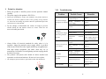
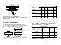
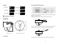
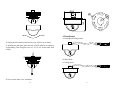
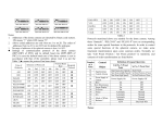
Installation and Operation Manual
for
Mini Dome Camera
CCTV
MODEL N0.:SP-606HB
SYSTEMS
Please read the operation manual carefully before installing and
Using this unit
2006021101
Insufficient
power
electrical
Index
Replace
Abnormal self-inspection
Switch on again
Bad connection of control
wire
Remove
Problems on main machine
Switch on
machine
Ball holder out of
control
Too heavy load or longer
distance of communication
Ⅰ.Points for Attention…………………………………1
main
Ⅱ.Description of Functions……………………………2
1. Connect
120 Ω
resistor
of
the
farthest ball holder
from the controller
and let others to be
broken;
Ⅲ.Setup of the speed dome camera……………………3
the
2. Increase
distributor.
code
Ⅳ.Installation of Products………………………………7
Ⅴ.Connection Drawing of the System for Reference…16
Ⅵ.Main Technical Specifications………….…….…….16
Ⅶ.Troubleshooting……………………………………
Normal problems and their causes and remedies mentioned above
are only for reference. Should you meet other special problems, you
can ask for technical support from your dealer directly.
19
……………18
I.
Points for Attention
1. Before the product is installed, please read the operation manual
carefully.
2. The power supply of the product is DC12V/1A.
VII.
Troubleshooting
Problem
3. During the transportation, storage and installation, the product should be
avoided from incorrect operations such as heavy pressing, strong vibration
etc., which can cause damage of product as there are sophisticated optical and
electronic devices inside the ball.
No action and images
when power is switched
on
4. Do not attempt to disassemble the camera. In order to prevent
electric shock, do not remove screws or covers. There are no
user-serviceable parts inside.
Abnormal
self-inspection. Images
with roaring sound of
the motor
5. Always follow all electrical standards for safety when it is in
operation. Adopt the particular power supply, which is provided
with the unit. RS-485 and video signal should keep enough distance
with high voltage equipments and cables when they are in
transmission. Precautions for anti-lightning and anti-surging should
be taken if necessary.
6. The products with plastic shell should be indoor installed and
operated to avoid rain and moisture. Do not use it in wet places.
7. The waterproof grade of metal low speed dome is IP66, and defend-burst.
Normal self-inspection
but no images
Successful
self-inspection but out
of control
Remedies
Power supply damaged or
insufficient power
Replace
Wrong
connection
power supply
Correct
Faults
circuits
in
of
engineering
Remove
Mechanical fault
Repair
Tilting camera
Place uprightly
Insufficient
power
electrical
Replace with qualified
power supply and let it
close to the ball holder
Wrong connection of VF
circuit
Correct
Bad connection of VF
circuit
Remove
Camera damaged
Replace
Wrong
connection
control signal wire
Images unstable
1
Possible Causes
of
Correct
Mismatched address
Reselect
Mismatched protocol
Adjust protocol to match
with the controller and
switch on again
Bad connection of VF
circuit
Remove
18
Installation
Ceiling
Installation/Wall
mounting/In-Ceiling Installation
ⅡDescription of Functions
Relative Temperature
10-75%(in case no condensation)
Operation Temperature
0℃~40℃
Waterproof
(metal)
IP66
The intelligent dome camera is a hi-tech CCTV product, which
incorporates the high-clarity color camera, panoramic speed-variable
PAN/TILT, multifunctional decoder into a whole. It can largely reduce
connection and installation processes of components in the system, rise
up reliability of the system and facilitate installation and maintenance.
Therefore it has advantages of beautiful appearance, compact structure
and easy operation.
Size
4.5″
CCD
1/3″Color Sony CCD
Horizontal
Range:
Horizontal
Speed:
Function
grade
Scanning
Scanning
360°
0-12°/s
Vertical Scanning Range:
0°~90°
Vertical Scanning Speed:
0-12°/s
Scanning Limitation:
Horizontal adjustable
TV format:
PAL format,1/4″color CCD
Resolution:
480TVL
Lowest Luminous:
0.1LUX
Built-In Lens:
Fix lens 2.8-16mm
Presetting Position:
32
Decoder:
Have
Cover Material:
Aluminum alloy,Vandal
whether proof
Input voltage
12V DC
Wattage:
12VA
17
proof
and
1. Built-in color video camera with vari focus lens
a. 4mm、6mm、8mm、12mm lens are available;
b. Automatic iris and shutter;
2. Integrated Multi-Protocol Decoder.
a. With built-in Decoder and integrated multi-protocol, the
customer can set up communication protocol and baud rates at
his discretion directly according to the need of the system. It is
completely compatible with over ten kinds of control system
form main manufacturers;
b. RS485 serial control and addresses of the dome 1-1023.
3. Integrated Speed-Variable PAN/TILT
a. Turning 0--360° horizontally and continuously with unlimited
positions and turning 90º vertically;
b. With 32 prepositions and data power off memory.
c. The dome camera can scan cubically between two positions
with dwelling time of 4s at each position and the scan speed of
7.5°/s;
d. With the tour locus setup function with data power-failure
memory which can be called;
e. The range of both horizontal and vertical speed is 0 - 12°/S;
Six patrol can be set up in maximum and each patrol can set up
sixteen preset positions with dwelling time fixed at 4s and the
tour speed is 7.5°/s;
2
III. Setup of the speed dome camera
V. Connection Drawing of the System for Reference
Before the installation of the product, first confirm the communication
protocol and the baud rate the controller of the system adopts, then set
the ID-CODE switch SW2 of the dome camera to be identical with that
in the system, in which SW1 is used to set the address of the dome and
SW2 is used to set the protocol type and the baud rate (see attached
tables 1, 2 and 3).
Dome Address Select
Protocol Select
JP1 1- 2 2- 3
120R ON OFF
JP1 is the 120 Ω terminal resistor for RS485 Bus. When
short-circuit terminal is set between “1-2”, the 120 Ω terminal resistor
is connected. while it is set between “2-3”, the resistor is opened. Take
care that on RS 485 Bus only one farthest spherical camera has the
terminal resistor connected while other devices should have their
terminal resistors opened.
DI P
ON
DI P
JP1 1- 2 2- 3
120R ON OFF
1 2 3 4 5 6 7 8 9 10
ON
1 2 3 4 5 6
JP1
VI.
Main Technical Specifications
Specifications
TV SYSTEM
NTSC
Image Sensor
1/4’ CCD Image Sensor
CCD total pixels
542(H)×496(V)
VF Output
Compound Signal 1.0Vp-p/75Ω
Scanning System
525 lines, 60 fields/sec
Power Supply
DC12V±10%
Power
Consumption
12VA(Fan/Heater excluded)
16
3
1.0A
Attached Table 1: The setup of the address of the dome:
Dome
Address
4) Put the connect cable across the bracket and surface, and fix the
wall mount;according the different environment to choice the bolts
by yourself;
Bit of
Switch
1
DIP
-1
ON
DIP
-2
OFF
DIP
-3
OFF
DIP
-4
OFF
DIP
-5
OFF
DIP
-6
OFF
DIP
-7
OFF
DIP
-8
OFF
DIP
-9
OFF
DIP
-10
OFF
2
OFF
ON
OFF
OFF
OFF
OFF
OFF
OFF
OFF
OFF
3
ON
ON
OFF
OFF
OFF
OFF
OFF
OFF
OFF
OFF
4
OFF
OFF
ON
OFF
OFF
OFF
OFF
OFF
OFF
OFF
5
ON
OFF
ON
OFF
OFF
OFF
OFF
OFF
OFF
OFF
6
OFF
ON
ON
OFF
OFF
OFF
OFF
OFF
OFF
OFF
7
ON
ON
ON
OFF
OFF
OFF
OFF
OFF
OFF
OFF
8
OFF
OFF
OFF
ON
OFF
OFF
OFF
OFF
OFF
OFF
9
ON
OFF
OFF
ON
OFF
OFF
OFF
OFF
OFF
OFF
10
OFF
ON
OFF
ON
OFF
OFF
OFF
OFF
OFF
OFF
11
ON
ON
OFF
ON
OFF
OFF
OFF
OFF
OFF
OFF
12
OFF
OFF
ON
ON
OFF
OFF
OFF
OFF
OFF
OFF
13
ON
OFF
ON
ON
OFF
OFF
OFF
OFF
OFF
OFF
14
OFF
ON
ON
ON
OFF
OFF
OFF
OFF
OFF
OFF
15
ON
ON
ON
ON
OFF
OFF
OFF
OFF
OFF
OFF
16
OFF
OFF
OFF
OFF
OFF
OFF
OFF
OFF
OFF
OFF
17
ON
OFF
OFF
OFF
OFF
OFF
OFF
OFF
OFF
OFF
18
OFF
ON
OFF
OFF
OFF
OFF
OFF
OFF
OFF
OFF
ON
ON
ON
ON
ON
…
1023
…
ON
ON
ON
ON
ON
5 ) Reference the connect way , connecting according the fig of
connection。
Attached Table1
15
4
Example:
ON
ON
1
2
3
4
5
6 7
8
9 10
ON
1
2
3
4
5
6 7
8
9 10
1
2
3
4
5
6 7
8
9 10
Speed Dome Addr ess=1
Speed Dome Addr ess=2
Speed Dome Addr ess=3
ON
ON
ON
1
2
3
4
5
6 7
8
9 10
Speed Dome Addr ess=4
1
2
3
4
5
6 7
8
9 10
Speed Dome Addr ess=18
1
2
3
4
5
6 7
8
9 10
Speed Dome Addr ess=1023
1. Addresses of the dome are denoted by binary code system in which
ON means
“1”; while OFF means “0”.
2. Above coded addresses are only from no.1 to no.18. The codes of
addresses from no.19 to no.1023 can be deduced by analogue.
3. All nine bits of the SW1 are used for addresses of the dome with its
range from 1 to 1023.
4. Before the installation of this product, arrange the address of the
dome well. All products have their default addresses before
leaving the factory and are increased from 1. The address of the
product is marked at the corresponding place, for example, “ID:
01” means the address of the product is 1.
5. When there are much dome camera are connected in the same
RS485 bus in parallel, the addresses could not be overlapped,
otherwise they’ll be activated simultaneously when they are
operated by the controller thus to affect the application of eh
product.
4) Reference the connect way, connect the wire according the board
cable.
D. Metal shell(wall mount)
1) Amending the way of code reference ceiling mount;
2) Tale off ceiling installation board,put the wall installation board
on,also pay attention the connect cable;
Put the connect cable across the fixed bracket,fix the dome with
installation bracket by Φ3x5 bolt;
Attached Table 2:
The setup of the communication protocols (DIP1-DIP4 of SW2) and the
default baud rates (last 2 bits of SW2) are as follows. In case the default
baud rate is not identical with that of the main controller, please set it to
be identical with that of the main controller as per Attached Table 3.
5
14
Attached table2
Type of
Selection of Protocols
communication
Normal Baud Rate
DIP-1
DIP-2
DIP-3
DIP-4
DIP-5
DIP-6
SAMSUNG
ON
OFF
OFF
OFF
OFF
ON
GOLDENSIGHTB01
ON
OFF
OFF
OFF
OFF
ON
PELCO-D
ON
ON
OFF
OFF
OFF
OFF
ON
OFF
OFF
OFF
ON
OFF
OFF
ON
OFF
ON
ON
ON
OFF
ON
PELCO-P/4800
PELCO-P/9600
5) Reinstall the metal shell,and fixed the screws;
6) Educe the system cable from the aperture,Fix the dome to ceiling
with Φ5x14 screw;
7) Reference the connect way of cable.
C. Metal Shell(Suspending mount)
1) Modify dial code way, please reference the ceiling mount;
2) Take off the ceiling mount board, use the suspending mount to
change it, also please pay attention of the
connect cable;
AELC
Notes to Attached Table 2:
The baud rates corresponding to the protocol are only for reference and
the customer can make modification based on the actual baud rate of
the system as per Attched Table3. Take care that ever for reference, the
coding swich should be set well can the system become effective
otherwise the default rate of the system is 2400bps.
Attached Table3
Coding Switch
1
5
6
2400bps
OFF
OFF
4800bps
ON
OFF
9600bps
OFF
ON
19200bps
ON
ON
Baud Rate
3) Put the cable cross the fixed bracket, then fixed the bracket and
dome;
13
2
Schematic drawing of codes:
6
3
4
Example
B. Metal Shell(Ceiling mount)
ON
ON
B01/ 9600Bps
1
2
3
4
5
6
SAMSUNG/ 9600Bps
ON
2
3
4
5
6
1
2
3
4
5
6
1
2
3
4
5
6
ON
AELC/ 9600Bps
1
2
3
4
5
6
PELCO- D/ 2400Bps
ON
PELCO- P/ 4800Bps
1
ON
1
2
3
4
5
6
PELCO- P/ 9600Bps
1) Drill the round hole(6cm) in ceiling, it is used for install the slot ring
and educe the connect cable;
2) Take out the fixed screws use special tools, then put is well;
Ⅳ. Installation of Products
4.1 Dimension
a) Plastic Shell
Scr ew on
130
18
t ake of f
92
32
105
3) Due to demand of waterproof, inside with airproof circle; when take
out the fixed screws, must use screwdriver to take the metal shell;
5
poi nt
Dimension of shel
Dimension of bottom board l
b) Metal Shell
4) Setting the dial switcher(reference the way of dial code switcher);
7
12
130
60
5
100
5
7.
6
R
t ake of f
Scr ew on
4.2 Installation
A. PlasticShell(Ceiling mount)
3) Setting the dial switcher(reference the way of dial code switcher);
4) Spinning the underpan, make the hole of PCB and hole of underpan
corresponding. Then using the screw of Φ5×14 to fix the dome with
ceiling.
B. Metal Shell
a) Ceiling mount
5) Screw on the dome cover with dome;
11
8
b) Suspend installation
300
6. 5
Φ7
3
Fixed bracket
Orientation aperture
Fixed bracket(with installation board) Fixed bracket(with wall interface)
86
4.3 Step of installation
40
130
Suspend installation board
A. Plastic Shell (Ceiling mount)
1) Drill the round hole(6cm) in ceiling, it is used for install the slot ring
and educe the connect cable;
2) Rotate the cover, pay attention for exert oneself point in bottom.
Please do not rotate the protection part of slip ring in bottom.
(salience part):
a) Wall mount
3
Bot t om r ot at i onal poi nt s
Wall mount board
9
10
SAFETY PRECAUTIONS
The lighting flash with a arrowhead symbol, in an equilateral triangle, is
intended to alert the user. There is uninsulated“dangerous voltage”presence
near by the product’s enclosure which may be risk of to persons.
The exclamation point within an equilateral triangle is intended to alert the user
to reference of the important operating and maintenance(servicing) instructions.
THE PRODUCT CODE MARKED ON THE BOTTTOM COVER.
PLEASE FILL THE CODE IN THE FOLLOWING BLANK. PLEASE
SAVING THIS SPECIFICATION CAREFULLY, SO THAT CHECKING
MODEL:__________________________________
PRODUCT CODE:________________________