1
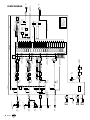
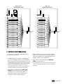
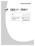
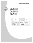
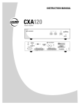
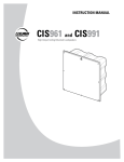
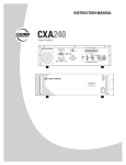
INSTRUCTION MANUAL
DX 1208
12x8 Digital Matrix Mixer and Signal Processor
1
2
3
4
5
INPUT
6
DX 1208
7
8
9/10
DX LINK RX
A
11/12
ANALOG
OUTPUT
B
C
D
G
REMOTES
CLIP
DX LINK ACTIVE
- 40
COMM
H
G
F
E
D
C
B
A
GND
GND
GND
GND
GND
GND
GND
GND
RS232
ADDRESS
LOGIC
S/PDIF
IN 9/10
IN 8
IN 7
OUT 3
OUT 2
OUT 1
IN 6
IN 5
IN 4
IN 3
IN 2
IN 1
GND
GND
GND
GND
GND
GND
GND
GND
GND
R
ETHERNET
DX LINK TX
MATRIX MIXER
H
L
ON
DX 1208
ON
OUTPUT
E
F
CLIP
- 40
IN 11/12
IN 6
L
R
IN 5
IN 4
IN 3
IN 2
GND
GND
GND
IN 1
GND
IN 8
IN 7
IN 6
IN 5
GND
GND
GND
GND
L
R
1. IMPORTANT SAFETY INSTRUCTIONS
1.
2.
3.
4.
5.
6. 7.
8.
9.
10.
11.
12.
13.
14.
Read these instructions.
Keep these instructions.
Heed all warnings.
Follow all instructions.
Do not use this apparatus near water.
Clean only with dry cloth.
Do not block any ventilation openings. Install in accordance with the
manufacturer's instructions.
Do not install near any heat sources such as radiators, heat registers,
stoves, or other apparatus (including amplifiers) that produce heat.
Do not defeat the safety purpose of the polarized or grounding-type
plug. A polarized plug has two blades with one wider than the other. A
grounding type plug has two blades and a third grounding prong. The wide
blade or the third prong are provided for your safety. If the provided plug
does not fit into your outlet, consult an electrician for replacement of the
obsolete outlet.
Protect the power cord from being walked on or pinched particularly at
plugs, convenience receptacles, and the point where they exit from the
apparatus.
Only use attachments/accessories specified by the manufacturer.
Use only with the cart, stand, tripod, bracket,
PORTABLE CART
or table specified by the manufacturer, or
WARNING
sold with the apparatus. When a cart is used,
use caution when moving the cart/apparatus
combination to avoid injury from tip-over.
Unplug this apparatus during lightning storms
or when unused for long periods of time.
Refer all servicing to qualified service
personnel. Servicing is required when the
apparatus has been damaged in any way, such as power-supply cord or
plug is damaged, liquid has been spilled or objects have fallen into the
apparatus, the apparatus has been exposed to rain or moisture, does not
operate normally, or has been dropped.
CAUTION
AVIS
RISK OF ELECTRIC SHOCK • DO NOT OPEN
RISQUE DE CHOC ELECTRIQUE
NE PAS OUVRIR
CAUTION: TO REDUCE THE RISK OF ELECTRIC SHOCK
DO NOT REMOVE COVER (OR BACK)
NO USER-SERVICEABLE PARTS INSIDE
REFER SERVICING TO QUALIFIED PERSONNEL
ATTENTION: POUR EVITER LES RISQUES DE CHOC
ELECTRIQUE, NE PAS ENLEVER LE COUVERCLE. AUCUN
ENTRETIEN DE PIECES INTERIEURES PAR L'USAGER. CONFIER
L'ENTRETIEN AU PERSONNEL QUALIFIE.
AVIS: POUR EVITER LES RISQUES D'INCENDIE OU
D'ELECTROCUTION, N'EXPOSEZ PAS CET ARTICLE
A LA PLUIE OU A L'HUMIDITE
15. Do not overload wall outlets and extension cords as this can result in a risk
of fire or electric shock.
16. This apparatus has been designed with Class-I construction and must be
connected to a mains socket outlet with a protective earthing connection
(the third grounding prong).
17. This apparatus has been equipped with a rocker-style AC mains power
switch. This switch is located on the rear panel and should remain readily
accessible to the user.
18. The mains plug or an appliance coupler is used as the disconnect device,
so the disconnect device shall remain readily operable.
19. NOTE: This equipment has been tested and found to comply with the limits
for a Class A, digital device, pursuant to Part 15 of the FCC Rules, and
the rules for Canada under ICES-003 - Feb 04. These limits are designed
to provide reasonable protection against harmful interference when the
equipment is operated in a commercial environment. This equipment
generates, uses, and can radiate radio frequency energy and, if not
installed and used in accordance with the instruction manual, may cause
harmful interference to radio communications. Operation of this equipment
in a residential area is likely to cause harmful interference in which
case the user will be required to correct the interference at his/her own
expense.
CAUTION: Changes or modifications to this device not expressly approved
by LOUD Technologies Inc. could void the user’s authority to operate the
equipment under FCC rules.
WARNING! This equipment has been designed to be installed
by qualified professionals only! There are many factors to be
considered when installing professional sound reinforcement
systems, including mechanical and electrical considerations, as well
as acoustic coverage and performance. EAW Commercial strongly
recommends that this equipment be installed only by a professional
sound installer or contractor.
WARNING — To reduce the risk of fire or
electric shock, do not expose this appliance to
rain or moisture.
CAUTION — Internal lithium battery. Danger
of explosion if battery is incorrectly replaced.
Replace only with the same or equivalent type.
The lightning flash with arrowhead symbol within an equilateral triangle is
intended to alert the user to the presence of uninsulated "dangerous voltage"
within the product's enclosure, that may be of sufficient magnitude to constitute
a risk of electric shock to persons.
Le symbole éclair avec point de flèche à l'intérieur d'un triangle équilatéral est
utilisé pour alerter l'utilisateur de la présence à l'intérieur du coffret de "voltage
dangereux" non isolé d'ampleur suffisante pour constituer un risque d'éléctrocution.
The exclamation point within an equilateral triangle is intended to alert the user
of the presence of important operating and maintenance (servicing) instructions
in the literature accompanying the appliance.
Le point d'exclamation à l'intérieur d'un triangle équilatéral est employé pour
alerter les utilisateurs de la présence d'instructions importantes pour le fonctionnement et l'entretien (service) dans le livret d'instruction accompagnant l'appareil.
Correct disposal of this product. This symbol indicates that this product should not be disposed of with your household waste, according to the WEEE Directive (2002/96/EC) and your national law. This product
should be handed over to an authorized collection site for recycling waste electrical and electronic equipment (EEE). Improper handling of this type of waste could have a possible negative impact on the environment
and human health due to potentially hazardous substances that are generally associated with EEE. At the same time, your cooperation in the correct disposal of this product will contribute to the effective usage of
natural resources. For more information about where you can drop off your waste equipment for recycling, please contact your local city office, waste authority, or your household waste disposal service.
2 – DX1208
Table of Contents
1. IMPORTANT SAFETY INSTRUCTIONS......................................... 2
2. INTRODUCTION............................................................................... 4
Key Features.................................................................................. 4
Unpacking...................................................................................... 4
Front Panel Features...................................................................... 5
Rear Panel Features....................................................................... 5
3. HARDWARE INSTALLATION.......................................................... 6
Connections................................................................................... 6
AC Power Considerations............................................................ 10
4. SOFTWARE INSTALLATION......................................................... 10
Computer Requirements.............................................................. 10
Installing the Drivers and DX Navigator...................................... 10
Establishing Communication Over USB....................................... 14
Communicating Over Ethernet..................................................... 14
Communicating Over RS232........................................................ 15
Upgrading the Firmware.............................................................. 15
5. TYPICAL HOOKUP DIAGRAM...................................................... 15
6. SPECIFICATIONS........................................................................... 16
DX1208 Specifications................................................................. 16
Disclaimer.................................................................................... 17
Block Diagram.............................................................................. 18
7. SERVICE INFORMATION............................................................... 19
Part No. 0028766-00 Rev. B 06/09
© 2009 LOUD Technologies Inc. All Rights Reserved.
DX1208 – 3
2. INTRODUCTION
The DX1208 is a 12-input, 8-output DSP matrix mixer
designed for use in a variety of commercial and installed
sound applications such as churches, courtrooms, convention
centers, and hotels. Eight inputs are mic/line capable, with
selectable 48-volt phantom power provided for each input.
These 8 inputs and the 8 outputs are accessed using Euroblock
detachable connectors. Four additional inputs on unbalanced
RCA connectors allow the user to “stack” inputs (inputs 5-8),
increasing the number of audio sources that can be connected.
An additional four digital inputs are available on S/PDIF
connectors with sample rate conversion to 48 kHz. All 12
inputs are included in the audio matrix and can be assigned
DSP functions prior to distributing signal at line level.
The DX1208 can also receive up to 6 logic inputs and
send up to 3 logic outputs, programmable via the included DX
Navigator control software. Control of the DX1208 via third
party systems (i.e., AMX and Crestron) is easily attained with
an RS-232C serial connection (DB9) on the rear panel. Two
RJ-45 connections are provided as well for linking multiple (up
to eight) DX Link enabled products together in a ring network
topology.
A remote control port (RJ-25 connector) is included on the
rear panel, facilitating the connection of two different types of
remotes (UR-1 and UR-2), all mounted on wall panels. Up to 10
remotes can be attached to the DX1208 (more when external
power is supplied), and each is individually addressable and
configurable.
The DX1208 is supplied with DX Navigator control
software that allows access to all of the system’s settings and
configurations using a personal computer (PC). The expected
range of user-adjustable processing, such as EQ filters, gates,
compressors, limiters, AGC, ducking and priority assignment,
delay, gain, and crossovers are included. The Automix feature
employs a gain sharing automixer, to keep the overall system
gain constant. In addition, up to 24 programmable presets are
available per DX1208, which can be used to store and recall
frequently used settings. The programming interface is flexible,
with connection via the USB port on the front panel, or the
Ethernet jack or DB9 connector on the rear panel.
The DX1208 is UL and CE approved. It is designed for
continuous use in professional fixed installation systems and
employs a universal power supply (100-240 VAC, 50/60 Hz).
4 – DX1208
Key Features
• 32-bit DSP and 24-bit Analog/Digital Conversion
• 8 balanced Mic/Line inputs on Euroblock connectors
• Individually selectable 48V phantom power on Mic/Line
inputs 1-8
• 4 additional unbalanced line inputs stacked to inputs 5-8 on
RCA connectors
• Inputs 9/10 and 11/12 on S/PDIF connectors for digital
inputs
• Gate, compressor/AGC, and six band EQ on each input
• Mute and solo button on each input
• 8 balanced line-level outputs on Euroblock connectors
• Limiter, eight band EQ plus two crossover filters, and delay
on each output
• 6 logic inputs and 3 logic outputs
• DX Link enables small installation networks, providing an
additional 16 inputs (IDX) and 16 outputs (ODX)
• Automix feature maximizes acoustic gain without feedback
• Adjustable ducking with 5 priority levels assignable to each
input (inputs 1-12 and IDX inputs 1-16)
• 1 remote control port for connection and control of up to 10
remotes
• 1 USB port on the front panel for control and programming
with a PC
• Rear panel DB9 connector for RS-232C communications
with third party devices (AMX, Crestron)
• Rear panel Ethernet connection can also be used for control
and programming
• Comprehensive graphical user interface using DX Navigator
software
Unpacking
Contents
Qty
Item
1
Detachable Line Cord 115 VAC
1
Detachable Line Cord 230 VAC
16
3-position Euroblock connectors for audio I/O
9
2-position Euroblock connectors for logic I/O
2
Rack Ears (installed on product)
1
CD-ROM containing DX Navigator installer
(Windows)
1
Instruction Manual (this document)
Front Panel Features
Rear Panel Features
The front panel consists mostly of indicators showing the
status of the DX1208, with the exception of the USB connector
for easy programming access with a PC.
7. IEC AC SOCKET
The DX1208 has a universal power supply, allowing it to
operate from any AC mains supply from 100 to 240 VAC,
50-60 Hz. The DX1208 comes with two IEC power cables,
one for 120 V operation and one for 220 V operation. Select
the power cable appropriate for your local AC power and
connect it to the IEC AC socket.
1. INPUT LEVEL INDICATORS
Each input channel has a pair of level indicators. The green
LED indicates the presence of a signal above –40 dBFS.
The red LED indicates when the signal is above –2 dBFS
and is close to clipping.
8. ON SWITCH
2. OUTPUT LEVEL INDICATORS
Use the ON switch to turn the DX1208 on and off.
Each output channel has a pair of level indicators. The green
LED indicates the presence of a signal above –40 dBFS.
The red LED indicates when the signal is above –2 dBFS
and is close to clipping.
9. REMOTES
This RJ-25 connector is used to connect to one or more
optional remote controls. Up to 10 UR-family remotes may
be connected in a daisy-chain to this remote control port
(more when external power is supplied). See “Connecting
the REMOTES” on page 9 for more information on using the
remote controls.
3. USB CONNECTOR
Use this standard USB connector to connect the DX1208 to
a PC with DX Navigator installed.
10. ADDRESS
4. DX LINK ACTIVE
Currently disabled, this multi-position rotary switch will be
implemented in future software updates.
This red LED lights continuously to indicate when a DX Link
enabled device is connected to the DX LINK RX connector
on the rear panel and is communicating correctly.
11. ETHERNET
This RJ-45 connector allows the DX1208 to be controlled
and programmed by a PC with a 10/100 Base-T Ethernet
connection.
5. COMM
This green LED lights to indicate communication activity
via the USB, RS-232, Ethernet, Remotes, or Logic Input
connections.
12. DX LINK RX/TX
These RJ-45 connectors are used to connect multiple DX
Link enabled devices together. The DX LINK RX connector
receives audio from devices that are located upstream in
the audio path, and the DX LINK TX connector transmits
audio to devices that are located downstream in the audio
path. See “Connecting the DX LINK RX/TX” on page 9 for
more information on using the DX Link connections.
6. ON
This green LED lights when the power switch is turned
on and the DX1208 is connected to an AC mains with
sufficient voltage for operation.
1
1
2
2
3
3
4
4
5
5
INPUT
6
INPUT
6
7
7
8
8
9/10
9/10
A
11/12
B
C
D
G
DX LINK ACTIVE
- 40
- 40
COMM
CLIP
DX LINK ACTIVE
A
B
C
D
DX 1208
DX LINK RX
G
REMOTES
H
G
F
E
D
GND
GND
GND
GND
GND
RS232
ADDRESS
LOGIC
- 40
C
B
A
GND
GND
GND
S/PDIFCOMM
IN 9/10
IN 8
IN 7
ETHERNET
DX LINK TX
DX LINK RX
ON
REMOTES
ETHERNET
DX LINK TX
IN 5
IN 4
IN 3
IN 2
IN 1
GND
GND
GND
GND
L
OUT 3
OUT 2
OUT 1
IN 6
IN 5
IN 4
IN 3
IN 2
IN 1
IN 8
IN 7
IN 6
IN 5
GND
GND
GND
GND
GND
GND
GND
GND
GND
GND
GND
GND
GND
IN 4
IN 3
IN 2
IN 1
GND
GND
GND
GND
IN 8
IN 7
IN 6
IN 5
GND
GND
GND
GND
R
R
IN 11/12
ANALOG
OUTPUT
H
G
F
E
D
C
B
A
GND
GND
GND
GND
GND
GND
GND
GND
RS232
ADDRESS
IN 6
L
R
DX 1208
MATRIX MIXER
H
L
ON
DX 1208
ON
OUTPUT
E
F
CLIP
ANALOG
OUTPUT - 40
MATRIX MIXER
H
CLIP
11/12
DX 1208
ON
OUTPUT
E
F
CLIP
LOGIC
OUT 3
OUT 2
OUT 1
IN 6
IN 5
IN 4
IN 3
IN 2
IN 1
GND
GND
GND
GND
GND
GND
GND
GND
GND
S/PDIF
IN 9/10
IN 8
IN 7
IN 6
IN 5
L
L
L
R
R
R
IN 11/12
DX1208 – 5
13. RS232
18. LOGIC I/O
This is an RS-232C port on a 9-pin (DB9) connector. It
connects to a personal computer or other compatible
control system for external control of the DX1208 settings.
This may be used instead of the USB port or the Ethernet
connection for programming the DX1208.
The DX1208 provides six logic inputs and three logic
outputs on Euroblock connectors. The inputs can be used
to control a variety of DX1208 functions via external
switching, such as preset recall or channel muting. The
outputs can be used to provide logic for external indicators
and switches to indicate a range of internal settings and
conditions.
14. ANALOG OUTPUTS A-H
Eight balanced line-level outputs are provided on these
Euroblock connectors, labeled A-H.
Each logic input and output is comprised of two pins, the
active pin and ground. See “Connecting the Logic I/O”
on page 8 for suggested logic input and output wiring
examples.
15. ANALOG INPUTS 1-8
Connect eight balanced mic or line-level inputs to these
Euroblock connectors. The input gain is adjusted in the DX
Navigator software application to accommodate a mic or
line-level signal. 48V phantom power can also be applied
to a microphone input by activating it in the DX Navigator
DX1208 user-interface.
3. HARDWARE INSTALLATION
The DX1208 ships with rack ears installed, which allows
the unit to be mounted in a standard 19" rack, requiring one
rack unit (1.75"). When mounting in a rack, use plastic washers
to protect the rack ears from the mounting screws.
16. ANALOG INPUTS 5-8
These RCA connectors accept unbalanced line-level
inputs (–10 dBV) to accommodate consumer sources such
as CD or MP3 players. The left and right inputs for each
channel are summed to mono internally. It is possible to
have a signal connected to both balanced (Euroblock) and
unbalanced (RCA) connectors for inputs 5-8. The signals are
summed together in the analog domain, just prior to A/D
conversion.
Note: Since the DX1208 is convection cooled with
ventilation slots on the sides and top, please allow one rack
space above the DX1208 to allow proper ventilation.
If you do not rack mount the DX1208, you may remove the
rack ears if desired.
Connections
17. S/PDIF IN 9/10 and 11/12
Connecting Balanced Sources
These RCA connectors are used to connect S/PDIF digital
inputs to the DX1208. The sample rate is automatically
detected and converted to 48 kHz for internal processing.
Use high-quality three-conductor cable for balanced input
connections. The better the shield, the better the audio signal
is protected from induced EMI and RFI.
Note: With screw-down Euroblock connectors, it’s best
to use stranded wire that is not tinned. Solder can “flow”
under the pressure of the screw-down terminal and cause the
connection to become loose.
1
2
3
4
5
INPUT
6
DX 1208
7
8
DX LINK RX
ON
REMOTES
A
11/12
ANALOG
OUTPUT
ETHERNET
DX LINK TX
B
C
D
G
MATRIX MIXER
H
CLIP
DX LINK ACTIVE
- 40
- 40
COMM
H
G
F
E
D
C
B
A
GND
GND
GND
GND
GND
GND
GND
GND
LOGIC
DX 1208
ON
OUTPUT
E
F
CLIP
RS232
ADDRESS
6 – DX1208
9/10
OUT 3
OUT 2
OUT 1
IN 6
IN 5
IN 4
IN 3
IN 2
IN 1
GND
GND
GND
GND
GND
GND
GND
GND
GND
S/PDIF
IN 9/10
IN 11/12
IN 8
IN 7
IN 6
IN 5
L
L
L
R
R
R
IN 4
IN 3
IN 2
IN 1
GND
GND
GND
GND
IN 8
IN 7
IN 6
IN 5
GND
GND
GND
GND
To connect a balanced mic or line-level signal:
Strip the wire back about 1/4" inch. Insert the wire as far
as it will go into the appropriate hole in the supplied Euroblock
connector. Tighten down the screw with a small slot-head
screwdriver. It is recommended that you use 20 or 22 gauge
wire with the Euroblock connectors. Wire the connectors as
indicated on the rear panel:
To connect an unbalanced line-level signal to Inputs 5-8:
Inputs 5-8 have unbalanced RCA input connectors as
well as balanced Euroblock connectors. This makes it easy to
connect input sources such as a CD player, MP3 player, or the
audio from a satellite TV receiver.
S/PDIF
IN 9/10
IN 8
IN 7
IN 6
IN 5
L
L
L
R
R
R
IN 1
GND
IN 11/12
+
– GND
Balanced input connection (Euroblock)
Connecting Unbalanced Sources
It may be necessary to connect a 2-conductor unbalanced
input to a balanced input on the DX1208.
To connect an unbalanced line-level signal to a
balanced input:
Follow the instructions for connecting a balanced line-level
signal above, but wire the connector as follows:
From Analog
Audio Source
Unbalanced input connection (RCA)
These inputs accept a stereo source, but the left and right
signals are combined into a mono signal before any processing
takes place. If there is a balanced signal connected to the
Euroblock connector for Inputs 5-8, the RCA and Euroblock
input signals are combined as well.
Connecting Digital Sources
The DX1208 provides two S/PDIF input connectors for
digital audio sources. Each S/PDIF input connector accepts two
channels of digital audio, for a total of four digital inputs (9/10
and 11/12).
IN 1
GND
S/PDIF
IN 9/10
IN 8
IN 7
IN 6
IN 5
L
L
L
R
R
R
IN 11/12
+
GND
Unbalanced input connection (Euroblock)
From Digital
Audio Sources
S/PDIF digital input connection
DX1208 – 7
Connecting the Balanced Outputs
As with the balanced input connectors, use high-quality
three-conductor cable for balanced output connections.
To connect to a balanced line-level output:
Strip the wire back about 1/4" inch. Insert the wire as far
as it will go into the appropriate hole in the supplied Euroblock
connector. Tighten down the screw with a small slot-head
screwdriver. It is recommended that you use 20 or 22 gauge
wire with the Euroblock connectors. Wire the connectors as
indicated on the rear panel:
A
GND
+
– GND
Navigator, along with the action (momentary or latching), and
the function that is affected by the logic input.
LOGIC
OUT 3
OUT 2
OUT 1
IN 6
IN 5
IN 4
IN 3
IN 2
IN 1
GND
GND
GND
GND
GND
GND
GND
GND
GND
LOGIC IN 1
+
GND
LOGIC IN wiring example
The logic outputs are open-collector outputs with internal
pull-up resistors. Connect the indicator or activation circuit
between the logic output and ground. The logic outputs are
normally active high (+5 VDC) and can supply up to 10 mA of
current each. The active state can be changed in the Logic I/O
screen in DX Navigator, along with the function that generates
the logic output.
LOGIC
OUT 3
OUT 2
OUT 1
IN 6
IN 5
IN 4
IN 3
IN 2
IN 1
GND
GND
GND
GND
GND
GND
GND
GND
GND
Balanced output connection (Euroblock)
+
Connecting the LOGIC I/O
GND
LOGIC OUT 3
There are six programmable logic inputs and three
programmable logic outputs. Each logic input and output
requires two connections, the active wire and ground.
To connect to a logic input or output:
Strip the wire back about 1/4" inch. Insert the wire as far
as it will go into the appropriate hole in the supplied Euroblock
connector. Tighten down the screw with a small slot-head
screwdriver. It is recommended that you use 20 or 22 gauge
wire with the Euroblock connectors. Wire the connectors as
indicated on the rear panel:
IN 1
GND
LOGIC OUT wiring example
Connecting a PC or Controller
The DX1208 can be controlled and programmed via the
USB port, the Ethernet port, or the RS-232 port.
The most common way to connect to the DX1208 is over
the USB port, which is why it is located on the front panel—to
provide easy access, especially when the unit is rack mounted.
Simply connect the USB port on the DX1208 to the USB
port on a personal computer with DX Navigator installed.
1
+
GND
LOGIC I/O connection
Laptop
Computer
USB connection
The logic inputs have internal pull-up resistors connected
to +3.3 VDC. Use a normally open switch connected between
the logic input and ground. When the switch is open, the logic
input is high (+3.3 VDC), and when the switch is closed, the
logic input is low (ground). The active state of the logic input is
normally low, but can be changed in the Logic I/O screen in DX
8 – DX1208
10 mA Maximum
2
3
4
5
INPUT
6
7
8
9/10
A
11/12
B
C
D
OUTPUT
E
F
ON
G
H
CLIP
CLIP
DX LINK ACTIVE
- 40
- 40
COMM
DX 1208
MATRIX MIXER
The DX1208 can also be connected to a PC via the Ethernet
port, provided the PC has an Ethernet port as well. Use a Cat5
or Cat5e Ethernet cable with RJ-45 connectors.
Note: Use a Cat5 or Cat5e crossover cable when
connecting the DX1208 directly to a PC. If you are connecting
through an Ethernet switch, use a straight-through cable.
DX 1208
DX LINK RX
ANALOG
OUTPUT
H
G
RS232
LOGIC
F
E
D
C
B
A
S/PDIF
IN 9/10
IN 8
IN 7
L
ON
REMOTES
ADDRESS
OUT 3
OUT 2
OUT 1
IN 6
IN 5
IN 4
IN 3
IN 2
R
ETHERNET
100-240VAC 50-60Hz 40W
IN 6
L
IN 4
IN 3
IN 2
IN 1
IN 8
IN 7
IN 6
IN 5
IN 5
L
IN 1
R
R
IN 11/12
DX LINK TX
Ethernet connection
An RS-232C serial port is also available for connecting
a PC or other controller. This is a DB9 female connector on
the DX1208 rear panel and requires a cable with a DB9 male
connector on the DX1208 end. The DX1208 is configured as a
device or Data Communications Equipment (DCE), which is to
be connected to a controller or Data Terminal Equipment (DTE)
and be controlled.
DX LINK RX
ANALOG
OUTPUT
H
G
RS232
LOGIC
F
E
D
C
B
A
S/PDIF
IN 9/10
IN 8
IN 7
L
ON
REMOTES
ADDRESS
OUT 3
OUT 2
OUT 1
IN 6
IN 5
IN 4
IN 3
IN 2
ETHERNET
DX LINK TX
R
When two or more DX1208s are connected together using
DX Link, one must be configured as a Master and the rest as
Slaves. This is done in the Settings window of DX Navigator,
and the audio is managed in the DXLink window.
IN 4
IN 3
IN 2
IN 1
IN 8
IN 7
IN 6
IN 5
Connect the TX connector on the master device to the RX
connector on the first slave device. Then connect the TX on the
slave to the RX on the next slave, and so on. Connect the TX
on the last slave back to the RX on the master to complete the
connection.
Master
DX 1208
DX LINK RX
ANALOG
OUTPUT
H
G
RS232
LOGIC
F
E
D
C
B
A
S/PDIF
IN 9/10
IN 8
IN 7
L
ON
REMOTES
ADDRESS
OUT 3
OUT 2
OUT 1
IN 6
IN 5
IN 4
IN 3
IN 2
R
ETHERNET
100-240VAC 50-60Hz 40W
IN 6
L
IN 4
IN 3
IN 2
IN 1
IN 8
IN 7
IN 6
IN 5
IN 5
L
IN 1
R
R
IN 11/12
DX LINK TX
IN 5
L
IN 1
R
100-240VAC 50-60Hz 40W
IN 6
L
These two RJ-45 connectors are provided to connect DX
Link enabled devices together and transfer audio among the
devices. Up to 16 channels of audio can be transmitted over
the DX link ring network using shielded CAT5 cable, and up to
8 DX Link devices can be connected together.
Note: Although the DX Link uses Cat5 or Cat5e network
cable, this is not “audio over Ethernet” and cannot use
standard network hardware such as switches or repeaters.
Laptop
Computer
DX 1208
Connecting the DX LINK RX/TX
R
IN 11/12
Slave
DX 1208
DX LINK RX
ANALOG
OUTPUT
H
G
RS232
LOGIC
F
E
D
C
B
A
S/PDIF
IN 9/10
IN 8
IN 7
L
ON
REMOTES
ADDRESS
OUT 3
OUT 2
OUT 1
IN 6
IN 5
IN 4
IN 3
IN 2
R
ETHERNET
100-240VAC 50-60Hz 40W
IN 6
L
IN 4
IN 3
IN 2
IN 1
IN 8
IN 7
IN 6
IN 5
IN 5
L
IN 1
R
R
IN 11/12
DX LINK TX
Slave
Laptop
Computer
or Other Controller
DX 1208
DX LINK RX
ANALOG
OUTPUT
H
G
RS232
LOGIC
F
E
D
C
B
A
S/PDIF
IN 9/10
IN 8
IN 7
L
ON
REMOTES
ADDRESS
OUT 3
OUT 2
OUT 1
IN 6
IN 5
IN 4
IN 3
IN 2
R
100-240VAC 50-60Hz 40W
ETHERNET
DX LINK TX
IN 6
L
R
IN 4
IN 3
IN 2
IN 1
IN 8
IN 7
IN 6
IN 5
IN 5
L
IN 1
R
IN 11/12
RS232 connection
A separate document is available that provides information
on port settings and control protocol for the RS-232
connection. Visit www.eaw.com for more information.
DX LINK connection
Connecting the REMOTES
An RJ-25 connector on the rear panel is used to connect
the optional remote control peripherals. You can connect
up to 10 remotes on the remote bus. More remotes can be
connected to the remote bus, provided that external power is
supplied to the additional remotes. Refer to the documentation
provided with the remote control units for more information.
There are currently two types of remote controls available
for the DX1208. Each remote has two RJ-25 connectors, one
for connecting the remote bus from the previous device and the
other for connecting to the next device. Each remote also has
an eight position DIP-switch for assigning its unique address.
DX1208 – 9
UR-1
The UR-1 has a rotary encoder and a function button to
fit a single-gang decora plate, and mounts in a single-gang
electrical box.
AC Power Considerations
The DX1208 has a built-in universal power supply and
can accept an AC voltage ranging from 100 V to 240 V. Each
DX1208 draws an average of 0.5 amps of AC line current at
120 VAC.
Warning: Always use a 3-conductor AC power cord with
a safety ground connection. Never remove the ground pin or
attempt to bypass it. This is very dangerous.
4. SOFTWARE INSTALLATION
UR-1
The encoder is used to increase or decrease the volume of
an input or output. A ring of 15 LEDs surrounding the encoder
indicates the relative audio level. The function button can be
programmed for a number of actions, such as "Mute an Input"
or "Recall a Priority." When the function is activated, the LED in
the button lights. Programming is done in the Remotes window
of DX Navigator.
UR-2
The UR-2 has four function buttons to fit a single-gang
decora plate, and mounts in a single-gang electrical box.
Each button can be programmed to perform a different action.
When a function is activated, the LED in the button lights.
Programming is done in the Remotes window of DX Navigator.
The DX Navigator software application is provided on a CDROM, which can be installed on a PC. It provides a graphical
user interface (GUI) for controlling the digital signal processing
(DSP) for multiple DX Series products, including the DX1208.
Check our website at www.eaw.com for software upgrades
as they become available.
Computer Requirements
DX Navigator requires an IBM compatible PC with the
Windows XP SP2 and above or Windows Vista operating
system. It is not designed to work with previous versions of
Windows or Macintosh operating systems.
Installing the Drivers and
DX Navigator
During the installation process, USB drivers are installed on
your computer's hard drive. USB drivers are necessary for the
computer to communicate with the DX1208 over the USB port.
This software installation is a two-step process and requires
running the New Hardware Wizard twice.
To install the software on a PC:
1. Make sure no other applications are running.
2. Insert the DX1208 CD into your PC’s CD drive, or download
the software from www.eaw.com.
UR-2
3. Click “Start > Run > Browse” and navigate to the CD drive
or the location on your hard drive where the file was
downloaded.
4. Double-click “DXNavigator_v1_xxx.exe (where xxx is the
revision level of the installation).
5. Click “OK” in the Run window.
10 – DX1208
6. The DX Navigator Setup Wizard will begin installing the
software on your computer’s hard drive.
9. You can accept the default directory, or specify a different
location to install the application. Click “Next” to continue.
Note: The following screenshots were taken on a computer
running Windows Vista. If you are using an earlier version
of Windows, the screens may appear slightly different.
7. Click “Next” and read the License Agreement. Click “I
Agree” to continue.
8. A warning about removing previous versions of DX
Navigator appears. Click “Next” to continue.
10.Wait a few moments while DX Navigator is installed on
the computer. The following window will appear when the
installation is complete. Leave the “Run DX Navigator” tick
box checked. Click “Finish” to complete the installation of
DX Navigator.
11.When DX Navigator opens, the following dialog box
appears, informing you where the drivers are located on
the hard drive (Program Files\EAW\Data\FTDI). Click “OK” to
continue.
DX1208 – 11
12.Connect the DX1208 USB port to a USB port on your
computer using a standard USB cable. Turn on the DX1208
and the New Hardware Wizard will start.
Select “Locate and install driver software (recommended).”
13.Select “I don’t have the disc. Show me other options.”
14.Select “Browse my computer for driver software
(advanced).”
12 – DX1208
15.Click the “Browse” button and navigate to C:\Program
Files\EAW\Data\FTDI\DX1208 (or other location if you chose
to install the drivers somewhere else). Click “Next” to
continue.
16.The installer will begin installing the driver software. A
warning may appear indicating that Windows can’t verify
the publisher of the driver software. Click ”Install this
driver software anyway.”
17.When the driver software has been installed, the following
screen notifies you that the software has been successfully
installed. This completes the first half of the driver
installation. Click “Close” to continue.
18.The “Found New Hardware Wizard” opens again. Click “I
don’t have the disc. Show me other options.”
19.Select “Browse my computer for driver software
(advanced).”
21.The installer will begin installing the driver software. A
warning may appear indicating that Windows can’t verify
the publisher of the driver software. Click ”Install this
driver software anyway.”
22.When the driver software has been installed, the following
screen notifies you that the software has been successfully
installed. Click “Close” to complete the driver installation.
20.Click the “Browse” button and navigate to C:\Program
Files\EAW\Data\FTDI\DX1208 (or other location if you chose
to install the drivers somewhere else). Click “Next” to
continue.
DX1208 – 13
Establishing Communication
Over USB
There are a few steps required to establish communication
between DX Navigator and the DX1208.
1. Click “Tools” in the top menu bar and select
“Communications” from the drop-down menu. The
Communications window opens.
5. Double-click the DX1208 icon in the “Found Devices” tab
to open the DX1208 interface. Click on the tabs across the
top of the DX1208 interface to open individual screens for
accessing controls and settings. The tabs include Input,
Priorities, Automix, Output, DXLink, Logic I/O, Remotes,
and Settings.
6. Refer to the Help file for detailed information about each
of the screens. To open the Help file, return to the DX
Navigator window, click “Help” in the top menu bar, and
select “DX1208 Help.”
Communicating Over Ethernet
You can connect your computer to the DX1208 directly with
an Ethernet connection, or indirectly over an Ethernet switch or
local area network (LAN).
Direct Connection
The DX1208 can be connected directly to your computer
using a crossover Cat5/Cat5e Ethernet cable.
2. Click the “COM Port” radio button and select the COM Port
that is assigned to the USB port that is connected to the
DX1208.
If you are not sure which COM Port is being used, open
the Device Manager on your computer, locate “Ports (COM
& LPT)” in the list and click the “+” sign in front of it. You
should see “EAWC DX Family USB Serial Port” followed by
a COM port number. This is the number you should select in
DX Navigator’s Communications window.
Click “OK” to close the Communications window.
3. Click “Go Online.” DX Navigator will begin to query the
DX1208 and the COMM LED on the DX1208 should light.
4. Once communication is established, the DX1208 icon
appears in the “Found Devices” tab with a green
checkmark in front of it.
When the DX1208 is connected via Ethernet, it requires
an IP address and will initiate a DHCP (Dynamic Host
Configuration Protocol) request for an IP address from a DHCP
server. Since no DHCP server exists on a direct connection, it is
necessary to assign a static IP address to the DX1208 in order
to communicate over Ethernet.
To assign a static IP address:
1. Connect your computer to the DX1208 using the USB port.
2. Open DX Navigator, click “Go Online,” and open the
“Settings” tab in the DX1208 GUI. In the IP section, select
“Static IP” and enter 169.254.xxx.xxx, where xxx can be
any number between 1 and 254. This is a private IP address
used for link-local addressing, but you can enter a privateuse IP address if you prefer. Remember the number that
you entered. You will need it again.
In the Subnet field, enter 255.255.0.0.
Note: Refer to RFC-3927 for information on link-local
addressing, and RFC-1918 for information on address
allocation for private internets.
3. Go offline and turn the DX1208 off.
Note: You must power cycle the DX1208 in order for the
Static IP address to take effect.
4. Connect the DX1208 to your computer with an Ethernet
cable and turn the DX1208 on.
5. In DX Navigator, click “Tools > Communications” in the top
menu bar.
6. Click the “Specify Target IP Addresses” radio button. Enter
the same IP address that you entered previously for the
DX1208 and click “Add” to add it to the list of IP Addresses
that DX Navigator will search for when it goes online.
14 – DX1208
7. Click “OK.” Click “Go Online” and the DX1208 icon will
appear in the “Found Devices” tab.
Indirect Connection
If you have multiple DX1208s installed in a system, you
may want to have them connected together in a LAN. This
allows you to connect your computer to the LAN and access
each DX1208 individually without having to physically change
connections.
Again, the DX1208 will send out a request for an IP
address. If there is a DHCP server on the network, it will assign
a unique IP address to each DX1208 on the network. If there
isn’t a DHCP server, then a unique static IP address will have to
be manually assigned to each DX1208 (see “To assign a static
IP address” above).
Once an IP address has been assigned to each DX1208:
1. Open DX Navigator and click “Tools > Communications” in
the top menu bar.
2. Select “Obtain IP Addresses By Broadcast” and click “OK.”
3. Click “Go Online.” DX Navigator will find all devices on
the network with an IP address and they will appear in the
“Found Devices” tab.
5. TYPICAL HOOKUP DIAGRAM
Note: The “Obtain IP Addresses By Broadcast” may not
work with Windows Vista yet. If you are running the Vista
operating system, it may be necessary to assign a static IP
address to each DX1208, even if there is a DHCP server on
the network, and select “Specify Target IP Addresses” in the
Communications window (see “To assign a static IP address”
in the previous section).
Communicating Over RS232
A rear panel RS-232C serial port is provided for additional
third party control options. Nearly every parameter that can be
controlled with DX Navigator can also be controlled using a
third party controller (i.e., AMX and Crestron models).
Port settings and control protocol will be provided in a
separate document. Visit our website for more information at
www.eaw.com.
Upgrading the Firmware
From time to time, EAW Commercial will release upgrades
for the internal operating firmware in the DX1208. This
can be downloaded from our website (www.eaw.com) to a
PC-compatible computer along with instructions on how to
upgrade the firmware.
DX1208 – 15
6. SPECIFICATIONS
DX1208 Specifications
INPUTS / OUTPUTS
Inputs 1-8:
Balanced, Euroblock terminals
Inputs 5-8:
Unbalanced, RCA connectors (summed with Inputs 5-8 on Euroblock connectors)
Inputs 9-12:
S/PDIF with SRC, RCA connectors
SRC range: 32 kHz to 96 kHz
Outputs A-H: Balanced, Euroblock terminals
DXLink TX:
16 channel output bus, RJ-45 connector
DXLink RX:
16 channel input bus, RJ-45 connector
Ethernet: 1 RJ-45 connector, rear panel
USB: 1 “B” type connector, front panel
RS232:
1 RS-232C serial port on a DB9 connector, rear panel
Logic Inputs: 6 inputs, contact closure, Euroblock terminals
Logic Outputs:
3 outputs, open-collector, Euroblock terminals
Remote:
1 remote bus with 24 VDC, RJ-25 connector
PANEL CONTROLS
Compressor
Threshold:
Ratio:
Attack:
Release:
Gain Makeup:
AGC:
Bypass:
+20 to –60 dB
1:1 to 20:1
1 to 5000 ms
50 to 5000 ms
0 to +40 dB, 0.5 dB steps
Enable/Disable
For each compressor
AGC (Automatic Gain Control)
Target: +20 to –40 dB
Threshold: +20 to –60 dB, Target > Threshold
Attack: 1 to 5000 ms
Ratio: 1:1 to 20:1
Gate
Threshold:
Attack:
Hold:
Release:
Depth:
Ducker
Priority:
Depth:
–60 to +20 dB
1 to 200 ms
1 to 5000 ms
1 to 5000 ms
–100 to 0 dB
Select 1 of 5 priority levels
0 to –60 dB, 0.5 dB steps
Outputs
Power On:
Rocker switch, rear panel
EQ Filters:
10 per output channel (8 parametric, 1 HP, 1 LP)
Address:
10-position rotary DIP switch
Parametric
Type:
Frequency:
Gain:
Bandwidth:
Symmetrical boost/cut
20 Hz to 20 kHz
±15 dB
0.016 to 4.000 octaves
(Q = 65 to 0.25)
Low/High Shelf
Slope:
Frequency:
6 dB / 12 dB per octave
20 Hz to 20 kHz
Low/High Pass
Slope:
Frequency:
12 dB per octave
20 Hz to 20 kHz
PANEL INDICATORS
Input Levels:
2-segment LEDs per channel
1 Green (–40 dBFS), 1 Red (Clip)
Output Levels:
2-segment LEDs per channel
1 Green (–40 dBFS), 1 Red (Clip)
Communication:
1 Green LED, lights to indicate
communications activity
DX Link:
1 Red LED, lights when valid signal is
received at DX LINK RX port
Power:
1 Green LED
SIGNAL PROCESSING
General:
1 x 32-bit DSP
24-bit A/D and D/A converters
2M x 16 Flash
1M x 16 SDRAM
Inputs EQ Filters:
6 per input channel
Parametric
Type:
Frequency:
Gain:
Bandwidth:
Symmetrical boost/cut
20 Hz to 20 kHz
±15 dB
0.016 to 4.000 octaves
(Q = 65 to 0.25)
Low/High Shelf
Slope:
Frequency:
6 dB / 12 dB per octave
20 Hz to 20 kHz
Low/High Pass
Slope:
Frequency:
Bypass
Bypass Filter:
Bypass EQ:
16 – DX1208
12 dB per octave
20 Hz to 20 kHz
For each individual filter
For all EQ filters
Crossover HP/LP
Slope: 6 dB per octave, Butterworth/Bessel
12, 18, 24 dB per octave, Butterworth
12, 18, 24 dB per octave, Bessel
12, 24 dB per octave Linkwitz-Riley
Bypass
Bypass Filter: For each individual filter
Parametric EQ Bypass:
For all EQ filters (excluding Xover filters)
Limiter
Threshold:
Ratio:
Attack:
Release:
Gain Makeup:
AGC:
Bypass:
+20 to –60 dB
1:1 to 20:1
1 to 5000 ms
50 to 5000 ms
0 to +40 dB
Enable/Disable
For each limiter
Delay:
0 to 2000 ms
AUDIO PERFORMANCE DATA
PHYSICAL
Sampling Rate:
48 kHz
A/D - D/A Converters:
24 bit
Dimensions (HxWxD):
1.75 in (1 RU) / 44mm x 19.00 in / 483 mm x
9.38 in / 238 mm
Maximum Input Level: Mic/Line = +24 dBu balanced
RCA = +10 dBV
Net Weight: 8.0 lb / 3.6 kg
Maximum Gain:
SAFETY STANDARDS
60 dB (Mic in to line out)
UL 60065, 7th Edition, 2006-11-20
CAN/CSA-C22.2 No. 60065-03, 1st Edition, 2006-04 + A1:2006
IEC 60065:2001 + Amd 1:2005
EN 60065:2002
Maximum Output Level:+24 dBu balanced
Output Impedance:
200Ω balanced
Total Harmonic Distortion (THD+N)
(1 kHz @ +22 dBu)
Analog In to Analog Out: < 0.01%
PC SYSTEM REQUIREMENTS
Common Mode Rejection Ratio (CMRR)
(1 kHz @ +60 dB Gain)
Mic In to Analog Out: > 80 dB
OS: Windows XP SP2, Windows Vista
Processor:
Pentium or faster
Crosstalk
(any analog input to adjacent channel):
< –90 dB
RAM:
16 MB minimum
32 MB recommended
Storage:
25 MB free disk space
Equivalent Input Noise (EIN)
Mic in to Analog out, max gain, 150 ohm termination:
–128 dBm unweighted
Display:
1024 x 768 pixels, 16-bit color (65,536 colors) or better
Frequency Response
Analog input to analog output:
20 Hz–20 kHz, ±1 dB
Disclaimer
Dynamic Range
Analog input to analog output:
>110 dB (A-weighted)
EAW Commercial continually engages in research related
to product improvement, new materials, and production
methods. Design refinements are introduced into existing
products without notice as a routine expression of that
philosophy. For this reason, any current EAW Commercial
product may differ in some respect from its published
description, but will always equal or exceed the original design
specifications unless otherwise stated.
ELECTRICAL
AC Power: 100–240 VAC, 50/60 Hz
Phantom Power:
+48 VDC
EAW Commercial is a trademark of LOUD Technologies Inc.
All other brand names mentioned are trademarks or
registered trademarks of their respective holders, and are
hereby acknowledged.
9.38 in/238 mm
9.13 in/232 mm
MANUFACTURED IN CHINA © 2007 LOUD TECHNOLOGIES INC.
"EAW" IS A REGISTERED TRADEMARK OF LOUD TECHNOLOGIES INC.
WARNING: TO REDUCE THE RISK OF FIRE OR ELECTRIC
SHOCK, DO NOT EXPOSE THIS EQUIPMENT TO RAIN OR
MOISTURE. DO NOT REMOVE COVER. NO USER SERVICEABLE
AVIS: RISQUE DE CHOC ELECTRIQUE — NE PAS OUVRIR PARTS INSIDE. REFER SERVICING TO QUALIFIED PERSONNEL.
REVISION
SERIAL NUMBER
19.00 in/483 mm
1
2
3
4
5
INPUT
6
7
8
9/10
A
11/12
B
C
D
OUTPUT
E
F
ON
G
H
CLIP
CLIP
DX LINK ACTIVE
- 40
- 40
COMM
DX 1208
MATRIX MIXER
1.75 in/44 mm
DX1208 – 17
18 – DX1208
PC
OR OTHER
CONTROL
DEVICE
PC
OR
ETHERNET
SWITCH
LOGIC
IN
(1 OF 6)
RS232
ETHERNET
+5V
USB
11/12
IDX 1-16
MIC PRE
0-60 dB
ADC
24-BIT
S/PDIF
RECEIVER
W/ SRC
PC
PHANTOM POWER
MIC PRE
0-60 dB
ADC
24-BIT
S/PDIF
RECEIVER
W/ SRC
R
L
+
–
G
+
–
G
9/10
DX LINK
RX
S/PDIF
IN
INPUT 5
LINE IN
INPUT 5
MIC/LINE
IN
+48 VDC
INPUT 1
MIC/LINE
IN
+48 VDC
PHANTOM POWER
CLIP
–40
IN 12
IN 11
IDX 2-16
IDX 1
IN 10
IN 9
FRONT PANEL
METER
CLIP
–40
FRONT PANEL
METER
CLIP
–40
FRONT PANEL
METER
CONTROL
PROCESSING
INPUT METER
INPUT METER
INPUT METER
INPUT METER
MUTE
MUTE
MUTE
MUTE
MUTE
SOLO
CONTROL
INPUT SOLO
MUTES ALL
OTHER INPUTS
SOLO
INPUT METER
32-BIT DSP
CH GAIN
–99 to +20 dB
CH GAIN
–99 to +20 dB
CH GAIN
–99 to +20 dB
CH GAIN
–99 to +20 dB
CH GAIN
–99 to +20 dB
REMOTE
CONTROL
+5V
GATE
BYPASS
REMOTE
CONTROL
(OPTIONAL)
LOGIC
OUT
(1 OF 3)
COMPRESSOR
BYPASS
6-BAND INPUT EQ
COMPRESSOR
GATE
PRIORITY
DUCKING
BYPASS
TO ADDITIONAL
REMOTE CONTROLS
(OPTIONAL)
IDX CHANNELS 2-16
(IDENTICAL TO IDX CH 1)
IDX 1
REMOTE
CONTROL
(OPTIONAL)
PRIORITY
DUCKING
BYPASS
INPUTS 6-8
(IDENTICAL TO IN 5)
PRIORITY
DUCKING
BYPASS
INPUTS 2-4
(IDENTICAL TO IN 1)
PRIORITY
DUCKING
BYPASS
INPUTS 11/12
(IDENTICAL TO IN 9/10)
BYPASS FILTER
6-BAND INPUT EQ
BYPASS
BYPASS FILTER
BYPASS
BYPASS FILTER
6-BAND INPUT EQ
BYPASS
COMPRESSOR
GATE
BYPASS
BYPASS
BYPASS
BYPASS
INPUT
PRIORITY
LOGIC
CONTROL
ODX 1-16
MATRIX MIXING BLOCK
(see next page)
ODX 1-16
MATRIX MIXING BLOCK
(see next page)
ODX 1-16
MATRIX MIXING BLOCK
(see next page)
ODX 1-16
MATRIX MIXING BLOCK
(see next page)
INPUTS 1-12; IDX 1-16
INPUTS 1-12; IDX 1-16
INPUTS 1-12; IDX 1-16
ODX 1-16
MATRIX MIXING BLOCK
(see next page)
INPUTS 1-12; IDX 1-16
INPUTS 1-12; IDX 1-16
ODX 1-16
MATRIX MIXING BLOCK
(see next page)
ODX 1-16
MATRIX MIXING BLOCK
(see next page)
INPUTS 1-12; IDX 1-16
INPUTS 1-12; IDX 1-16
ODX 1-16
MATRIX MIXING BLOCK
(see next page)
INPUTS 1-12; IDX 1-16
INPUTS 1-12; IDX 1-16
ODX 1-16
MATRIX MIXING BLOCK
(see next page)
ODX 1-16
MATRIX MIXING BLOCK
(see next page)
INPUTS 1-12; IDX 1-16
INPUTS 1-12; IDX 1-16
ODX 1-16
MATRIX MIXING BLOCK
(see next page)
INPUTS 1-12; IDX 1-16
ODX 1-16
MATRIX MIXING BLOCK
(see next page)
ODX 1-16
MATRIX MIXING BLOCK
(see next page)
ODX 1-16
MATRIX MIXING BLOCK
(see next page)
ODX 1-16
MATRIX MIXING BLOCK
(see next page)
INPUTS 1-12; IDX 1-16
INPUTS 1-12; IDX 1-16
INPUTS 1-12; IDX 1-16
ODX 1-16
MATRIX MIXING BLOCK
(see next page)
OUTPUTS A-H
MATRIX MIXING BLOCK
(see next page)
INPUTS 1-12; IDX 1-16
INPUTS 1-12; IDX 1-16
OUTPUTS A-H
MATRIX MIXING BLOCK
(see next page)
OUTPUTS A-H
MATRIX MIXING BLOCK
(see next page)
INPUTS 1-12; IDX 1-16
INPUTS 1-12; IDX 1-16
OUTPUTS A-H
MATRIX MIXING BLOCK
(see next page)
INPUTS 1-12; IDX 1-16
INPUTS 1-12; IDX 1-16
OUTPUTS A-H
MATRIX MIXING BLOCK
(see next page)
INPUTS 1-12; IDX 1-16
OUTPUTS A-H
MATRIX MIXING BLOCK
(see next page)
INPUTS 1-12; IDX 1-16
OUTPUTS A-H
MATRIX MIXING BLOCK
(see next page)
OUTPUTS A-H
MATRIX MIXING BLOCK
(see next page)
INPUTS 1-12; IDX 1-16
MATRIX MIXER
WITH AUTOMIX
ODX 1
MUTE
OUT A
BYPASS
BYPASS FILTER
–99 to
+20 dB
FADER
MUTE
MUTE
DELAY
EAW COMMERCIAL
DX1208
BLOCK DIAGRAM
(04.06.09.DF)
FADER
FADER
FRONT PANEL
METER
CLIP
–40
BYPASS FILTER
X-OVER
OUTPUT METER
ODX CHANNELS 2-16
(IDENTICAL TO ODX CH 1)
LIMITER
OUTPUT SOLO
SOLO
MUTES ALL
CONTROL OTHER OUTPUTS
SOLO
8-BAND OUTPUT EQ
OUTPUT
24-BIT
+
– OUTPUT
A
G
DX LINK
TX
OUTPUTS B-H
(IDENTICAL TO OUT A)
ODX 1-16
DAC
Block Diagram
OUTPUTS A-H
MATRIX MIXING BLOCK
AUTOMIX
INPUT METER
ODX 1-16
MATRIX MIXING BLOCK
AUTOMIX
INPUT METER
AUTOMIX
ENABLE AND
LOGIC
CONTROL
ON/OFF
ENABLE
FADER
ENABLE
AUTOMIX
FADER
INPUT 1
INPUT 1
–99 to
+20 dB
INPUT 2
SAME AS ABOVE
–99 to
+20 dB
INPUT 2
SAME AS ABOVE
INPUT 3
SAME AS ABOVE
INPUT 3
SAME AS ABOVE
INPUT 4
SAME AS ABOVE
INPUT 4
SAME AS ABOVE
INPUT 5
SAME AS ABOVE
INPUT 5
SAME AS ABOVE
INPUT 6
SAME AS ABOVE
INPUT 6
SAME AS ABOVE
INPUT 7
SAME AS ABOVE
INPUT 7
SAME AS ABOVE
INPUT 8
SAME AS ABOVE
INPUT 8
SAME AS ABOVE
INPUT 9
SAME AS ABOVE
INPUT 9
SAME AS ABOVE
INPUT 10
SAME AS ABOVE
INPUT 10
SAME AS ABOVE
INPUT 11
SAME AS ABOVE
INPUT 11
SAME AS ABOVE
INPUT 12
SAME AS ABOVE
INPUT 12
SAME AS ABOVE
IDX 1
SAME AS ABOVE
IDX 1
SAME AS ABOVE
IDX 2
SAME AS ABOVE
IDX 2
SAME AS ABOVE
IDX 3
SAME AS ABOVE
IDX 3
SAME AS ABOVE
IDX 4
SAME AS ABOVE
IDX 5
SAME AS ABOVE
MIX MASTER
OUTPUT METER
+
ENABLE
FADER
ANALOG
OUTPUT
–99 to
+20 dB
IDX 4
SAME AS ABOVE
IDX 5
SAME AS ABOVE
IDX 6
SAME AS ABOVE
IDX 6
SAME AS ABOVE
IDX 7
SAME AS ABOVE
IDX 7
SAME AS ABOVE
IDX 8
SAME AS ABOVE
IDX 8
SAME AS ABOVE
IDX 9
SAME AS ABOVE
IDX 9
SAME AS ABOVE
IDX 10
SAME AS ABOVE
IDX 10
SAME AS ABOVE
IDX 11
SAME AS ABOVE
IDX 11
SAME AS ABOVE
IDX 12
SAME AS ABOVE
IDX 12
SAME AS ABOVE
IDX 13
SAME AS ABOVE
IDX 13
SAME AS ABOVE
IDX 14
SAME AS ABOVE
IDX 14
SAME AS ABOVE
IDX 15
SAME AS ABOVE
IDX 15
SAME AS ABOVE
IDX 16
SAME AS ABOVE
IDX 16
SAME AS ABOVE
MIX MASTER
OUTPUT METER
+
ENABLE
FADER
ODX
OUTPUT
–99 to
+20 dB
7. SERVICE INFORMATION
In the event that your DX1208 should require servicing,
please follow these instructions:
1. Call EAW Commercial Tech Support at 1-800-992-5013, 7
am to 5 pm PST (Monday-Friday) to verify the problem and
obtain a Return Authorization (RA) Number. Be sure to have
the serial number of the unit when you call. You must have
a Return Authorization Number in order to obtain warranty
service at an authorized service center. You can also
contact EAW Commercial via email at [email protected],
or through our website at: www.eaw.com/ContactUs
3. Include a legible note stating your name, return shipping
address (no P.O. boxes), daytime phone number, and Return
Authorization Number. Give us a detailed description of the
problem, including how we can duplicate it.
4. Write the Return Authorization Number in BIG BOLD
PRINT on the top of the box.
5. Tech Support will tell you where to ship the unit when you
call for an RA Number. We suggest insurance for all forms
of cartage.
2. Pack the unit in its original packaging. This is very
important. LOUD Technologies is not responsible for
any damage that occurs during shipping due to nonconventional packaging. Original packaging helps to
minimize the possibility of shipping damage.
DX1208 – 19
EAW Commercial A LOUD Technologies Inc. Company
EAW Commercial | One Main Street | Whitinsville, MA 01588 USA | TEL toll free within US/Canada 800-992-5013
TEL outside US 508-234-6158 | FAX 508-234-8251 | www.eaw.com
© 2009 LOUD Technologies Inc. All Rights Reserved.