1
Service Manual
DECcolorwriter 1000
Color Printer
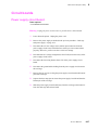
Warning
The following servicing instructions are for
use by qualified service personnel only. To
avoid personal injury, do not perform any
servicing other than that contained in
operating instructions unless you are qualified
to do so.
First printing February 1994
Order Number: EK-LF02E-FM.A01
Digital Equipment Corporation
Maynard, Massachusetts U.S.A.
If acquired subject to FAR or DFARS, the following shall apply:
n
Unpublished — rights reserved under the copyright laws of the United States.
n
Restricted Rights Legend — Use, duplication or disclosures by the government is subject to restrictions as set forth in
subparagraph (c) (1) (ii) of the Rights in Technical Data and Computer Software at DFARS 252.227-7013, or in subparagraph
(c) (2) of the Commercial Computer Software – Restricted Rights clause at FAR 52.227-19, as applicable. Tektronix, Inc.,
P.O. Box 1000, Wilsonville, Oregon 97070-1000.
Adobe™ and PostScript™ are trademarks of Adobe Systems, Incorporated which may be registered in certain jurisdictions.
Times™, Helvetica™, and Palatino™ are trademarks of Linotype-Hell AG and/or its subsidiaries.
Other marks are trademarks or registered trademarks of the companies with which they are associated.
PANTONE®* Colors generated by the DECcolorwriter 1000 are three-color process simulations and may not match
PANTONE-identified solid color standards. Use current PANTONE Color Reference Manuals for accurate colors.
PANTONE Color simulations are only obtainable on these products when driven by qualified Pantone-licensed software
packages. Contact Pantone, Inc. for a current list of qualified licensees.
* Pantone, Inc.’s check-standard trademark for color reproduction and color reproduction materials.
© Pantone. Inc., 1988.
Novell® and NetWare® are registered trademarks of Novell, Inc.
TCP/IP is a trademark of FTP Software. Copyright (c) 1986, 1987, 1988, 1989 by FTP Software, Inc. All rights reserved.
PC/TCP for DOS is based on a set of programs originally designed and developed by the Massachusetts Institute of Technology.
FTP Software has made extensive modifications and enhancements to the M.I.T. programs.
Users safety summary
Terms in manual: CAUTION
WARNING
Conditions that can result in damage to the product.
Conditions that can result in personal injury or loss of life.
Power source: Do not apply more than 250 volts RMS between the supply conductors or between either supply conductor
and ground. Use only the specified power cord and connector. Refer to a qualified service technician for changes to the cord or
connector.
Operation of product: Avoid electric shock by contacting a qualified service technician to replace fuses inside the product.
Do not operate without the covers and panels properly installed. Do not operate in an atmosphere of explosive gases.
Safety instructions: Read all installation instructions carefully before you plug the product into a power source.
Terms on product: CAUTION A personal injury hazard exists that may not be apparent. For example, a panel may cover
the hazardous area. Also applies to a hazard to property including the product itself.
DANGER A personal injury hazard exists in the area where you see the sign.
Care of product: Disconnect the power plug by pulling the plug, not the cord. Disconnect the power plug if the power cord
or plug is frayed or otherwise damaged, if you spill anything into the case, if product is exposed to any excess moisture, if
product is dropped or damaged, if you suspect that the product needs servicing or repair, and whenever you clean the product.
Ground the product: Plug the three-wire power cord (with grounding prong) into grounded AC outlets only. If necessary,
contact a licensed electrician to install a properly grounded outlet.
Symbols as marked on product:
DANGER high voltage:
Protective ground (earth) terminal:
Use caution. Refer to the manual(s) for information:
!
WARNING: If the product loses the ground connection, usage of knobs and controls (and other conductive parts) can cause an
electrical shock. Electrical product may be hazardous if misused.
Service safety summary
For qualified service personnel only: Refer also to the preceding Users Safety Summary.
Do not service alone: Do not perform internal service or adjustment of this product unless another person capable of
rendering first aid or resuscitation is present.
Use care when servicing with power on: Dangerous voltages may exist at several points in this product. To avoid
personal injury, do not touch exposed connections and components while power is on.
Disconnect power before removing the power supply shield, soldering, or replacing components.
Do not wear jewelry: Remove jewelry prior to servicing. Rings, necklaces, and other metallic objects could come into
contact with dangerous voltages and currents.
Power source: This product is intended to operate from a power source that will not apply more than 250 volts rms between
the supply conductors or between either supply conductor and ground. A protective ground connection by way of the grounding
conductor in the power cord is essential for safe operation.
Contents
1
General Information
DECcolorwriter 1000 1-2
Plain-paper printing 1-2
Print engine assemblies 1-3
Combination sensors and their meanings 1-5
Transfer roll type sensing 1-5
Media tray type sensing 1-6
Image processor boards 1-7
Rear panel 1-8
Front panel 1-10
Front panel LED service mode error codes
Specifications 1-12
Regulatory specifications 1-16
2
1-11
Installing the Printer and Drivers
Pre-install questions for customers 2-2
Unpacking 2-5
Inventory for the DECcolorwriter 1000 printer 2-5
Setting up the printer 2-7
Cabling the printer 2-8
Connecting the printer to a Macintosh 2-8
LocalTalk connection to a Macintosh 2-8
Connecting the printer to a PC 2-8
Direct connection to a PC 2-8
Connecting the printer to a workstation 2-9
Direct connection to a workstation 2-9
Turning on the printer 2-10
The startup page 2-10
The configuration page 2-11
Driver and communication setup 2-13
Loading the Macintosh driver 2-13
Installing the custom driver for Windows 3.1 2-14
Configuring the custom Windows printer driver 2-14
Updating the standard Microsoft Windows PostScript driver 2-17
Installing the printer driver for OS/2 Version 2 2-17
Configuring the printer's serial port for a PC 2-20
DECcolorwriter 1000 2-20
Using printcap to configure a Unix workstation for the printer's serial port
2-22
Service Manual
v
3
Verifying the Printer and Host Connections
Verifying printing to a Macintosh 3-1
Selecting the printer via the Chooser 3-1
Print the directory from Macintosh 3-2
Verifying that an application communicates to the printer 3-2
Using the Error Handler utility 3-3
Verifying printing to a PC 3-3
DOS connection verification 3-3
Windows 3.1 driver verification 3-4
OS/2 connection verification 3-5
Veryifing printing to a PC using the Error Handler utility 3-6
Verifying printing to a workstation using the Error Handler utility
4
Key Operator Training
Printer controls and indicators
Loading media 4-3
Cleaning 4-3
Clearing paper jams 4-4
Warranty information 4-4
Supplies ordering 4-5
5
4-2
Theory of Operation
Print engine 5-2
Wax transfer — the engine's printing technology
The print process 5-2
Plain-paper printing 5-4
Image data 5-5
Creating colors 5-5
Engine control board block description 5-6
CPU 5-7
Interface buffers 5-7
Data controller and line buffers 5-7
Heat controller (dot compensation) 5-7
Thermal head controller 5-8
Thermal head 5-8
Mechanical controller 5-8
Internal test pattern generator 5-8
vi
DECcolorwriter 1000
5-2
3-7
Paper path in operation 5-9
Paper pick-up 5-9
Drum loading 5-11
Printing 5-12
Print unloading 5-14
Power supply 5-15
DECcolorwriter 1000 image processor 5-17
Image rendering technology 5-17
6
Troubleshooting
System power-up sequence 6-1
Print engine troubleshooting 6-2
Verifying image processor operation by using the Test Pattern Generator 6-2
Verifying print engine operation by using its self-test print 6-3
Verifying power supply operation 6-3
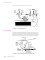
Measuring power supply voltages 6-3
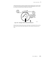
Inspecting the power supply fuses 6-5
Testing for a shorted motor 6-6
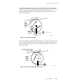
+24 VDC safety interlocks 6-6
Testing motor resistances 6-8
Media jams and the paper path 6-8
Media-based problems 6-8
Paper-pick errors 6-9
Paper-clamping errors 6-10
Print-eject jams 6-11
Checking the paper-feed motor and drive train 6-11
Media skews passing through the paper path 6-12
Transfer roll jam 6-12
Printing and print quality problems 6-13
Streaks or lines in the print parallel to the long axis of printing 6-13
Streaks or lines in the print parallel to the short axis of printing 6-13
White portion of print is colored 6-14
Color is uneven 6-14
Not printing 6-15
Printing too light or too dark 6-16
Image is offset or cut off 6-16
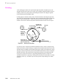
Wrinkling 6-17
Service Manual
vii
Print engine self-diagnostics 6-18
Starting service mode (self-diagnostics) 6-18
Displaying error codes on the front panel 6-18
Problems and solutions 6-19
Print engine error codes and their causes 6-19
Power problems 6-24
Front panel indicators 6-24
Macintosh printing problems 6-25
PC DOS printing problems 6-26
Windows printing problems 6-27
Workstation printing problems 6-28
DECcolorwriter 1000 image processors 6-29
Image processor normal operation indicators 6-29
Image processor hard and soft error indicators 6-29
Verifying the image processor's operation 6-29
Image processor self-diagnostics 6-30
Image processor rear panel switches for self-testing 6-30
The rear panel LED flashing in a regular one flash-per-second rate means no errors were detected
and that the image processor's CPU is running. 6-31
Printing the configuration page 6-31
Resetting the DECcolorwriter 1000’s NVRAM 6-32
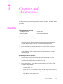
7
Cleaning and Maintenance
Cleaning 7-1
Lubrication 7-2
Inspecting 7-3
Replacements 7-4
viii
DECcolorwriter 1000
8
FRU Disassembly/Assembly
Required tools 8-1
Lower tray assembly 8-2
Printer cabinet panels 8-3
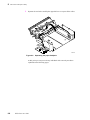
Paper-feed module 8-5
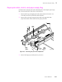
Accessing the pick roller, aligning roller, and the lower feed roller 8-6
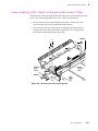
Paper-pick roller, clutch, and paper-empty flag 8-9
Lower aligning roller, clutch, and paper-pass sensorþ1þflag 8-11
Removing the upper aligning roller 8-13
Removing the feedþroller 8-14
Removing the exitþrollers 8-15
Bail roller assembly 8-16
Thermal head 8-17
Drum 8-19
Motors 8-23
Paper-feed motor 8-23
Drum motor 8-24
Transfer roll take-upþmotor 8-25
Thermal head lift motor 8-27
Sensors and switches 8-29
Paper-pass sensorþ1 and paper-empty sensor 8-29
Thermal head position sensors 8-29
Transfer roll mark sensors 8-29
Paper-pass sensorþ2 and trayþsensor 8-30
Transfer roll lowþsensor 8-33
Paper clamp sensor 8-34
Card cage and power supply 8-35
Circuit boards 8-37
Power supply circuit board 8-37
Paper-feed circuitþboard 8-39
Engine control board 8-39
Card cage interconnect board 8-41
I/O board 8-42
Image processor board 8-43
RAM SIMM 8-44
Font module 8-45
Service Manual
ix
9
Checks and Adjustments
Required tools summary 9-1
Printing test patterns 9-2
Printer self-checks 9-4
Thermal head motor check 9-5
Transfer roll feed check 9-5
Paper-path check 9-6
Tray select 9-6
Reflective sensor auto-calibration 9-7
Switch and interrupt sensor checks 9-8
Calibrating the transfer roll mark sensors (reflective sensors)
Calibrating the paper clamp sensor (reflective sensor) 9-10
Drum belt tension adjustment 9-11
Top margin adjustment 9-12
Adjusting for best print quality 9-14
Thermal head temperature adjustment 9-14
Thermal head pitch (to correct speckle and wrinkle) 9-16
Paper clamp adjustment (to correct misregistration) 9-18
A
Field Replaceable Units List
B
Test Patterns
C
Wiring Diagrams
D
Test Pattern Generator
Index
x
DECcolorwriter 1000
9-10
Service Manual
xi
Figures
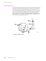
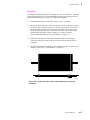
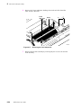
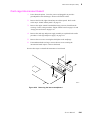
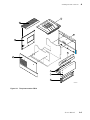
Figure 1-1.
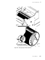
The DECcolorwriter 1000 (shown with the Lower Tray Assembly)
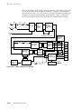
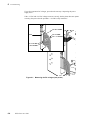
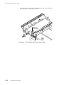
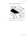
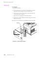
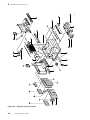
Figure 1-2.
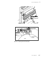
Internal features of the DECcolorwriter 1000 print engine
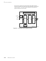
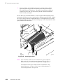
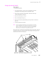
Figure 1-3.
Sensors and switches on the DECcolorwriter 1000 print engine
Figure 1-4.
Features of the DECcolorwriter 1000 image processor board
Figure 1-5.
DECcolorwriter 1000 rear panel
Figure 1-6.
DECcolorwriter 1000 front panel
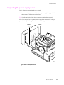
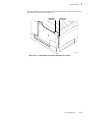
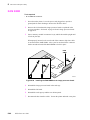
Figure 2-1.
The DECcolorwriter 1000 packaging
Figure 5-1.
The thermal-wax transfer print process
Figure 5-2.
Print engine board block diagram
Figure 5-3.
The paper pick process
Figure 5-4.
Paper clamp opening to receive a sheet of paper
Figure 5-5.
Clamping the paper
Figure 5-6.
Positioning the paper for printing
Figure 5-7.
Printing on the paper
Figure 5-8.
Raising the thermal head between passes
Figure 5-9.
Ejecting the print
1-1
1-3
1-4
1-7
1-9
1-10
2-6
5-3
5-6
5-10
5-11
5-11
5-12
5-12
5-13
5-14
Figure 5-10. Power supply block diagram 5-16
Figure 5-11. The image processor graphics pipeline 5-18
Figure 6-1.
Measuring the DC voltages (test points)
Figure 6-2.
Locating the fuses
Figure 6-3.
24 VDC safety interlocks (top and front covers)
Figure 6-4.
Proper front idler roller-to-drum alignment (to prevent wrinkling)
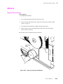
Figure 7-1.
Lubricating the clutches
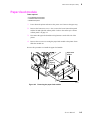
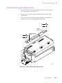
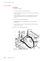
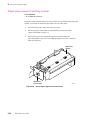
Figure 8-1
Removing the Lower Tray Assembly
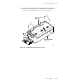
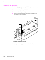
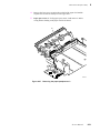
Figure 8-2
Removing the cabinet panels
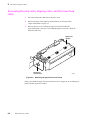
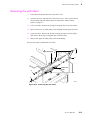
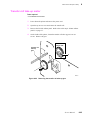
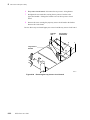
Figure 8-3
Removing the paper-feed module
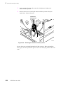
Figure 8-4
Removing the paper-feed circuit board
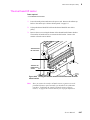
Figure 8-5
Removing the paper-feed unit screws
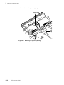
Figure 8-6
Separating the paper-feedþunit
Figure 8-7
Removing the pick roller andþclutch
Figure 8-8
Removing the paper-empty flag
Figure 8-9
Removing the lower aligningþroller
Figure 8-10
Removing the paper-pass sensor 1 flag
Figure 8-11
Removing the upper aligning roller
Figure 8-12
Removing the feed roller
8-14
Figure 8-13
Removing the exit rollers
8-15
6-4
6-5
6-7
6-17
7-3
8-2
8-4
8-5
8-6
8-7
8-8
8-9
8-10
8-11
8-12
8-13
Service Manual
xi
Figure 8-14
Removing the bail roller assembly
Figure 8-15
Removing the thermal head
Figure 8-16
Removing the drum belt and pulley
Figure 8-17
Removing the front idlerþroller
Figure 8-18
Removing the drum's right end bushing
Figure 8-19
Removing the drum
Figure 8-20
Removing the paper-feedþmotor
Figure 8-21
Removing the drum motor
Figure 8-22
Removing the transfer roll take-up gear
Figure 8-23
Removing the transfer roll take-up motor
Figure 8-24
Freeing the thermal head drive belt and thermal head lift motor bracket
Figure 8-25
Removing the thermal head liftþmotor
8-28
Figure 8-26
Removing the paper-feed circuit board
8-30
Figure 8-27
Removing the paper-passþsensor 2
Figure 8-28
Removing the tray sensors circuit board
Figure 8-29
Removing the transfer roll low sensor
Figure 8-30
Removing the paper clamp sensor
Figure 8-31
Disconnecting the wiring harnesses and removing the card cage
Figure 8-32
Removing the card cage and power supply
Figure 8-33
Removing the power supply circuit board
Figure 8-34
Disconnecting the wiring harnesses
8-39
Figure 8-35
Removing the engine control board
8-40
Figure 8-36
Removing the interconnectþboard
Figure 8-37
Removing the I/O board
Figure 8-38
Removing the image processor board
Figure 8-39
Installing the RAM SIMM on the image processor board
Figure 8-40
Installing the font SIMM on the image processor board
Figure 9-1
Engine control board DIP switches
Figure 9-2
Tensioning the drum belt
Figure 9-3
Adjusting the thermal head pitch
Figure 9-4
Setting the paper clamp adjustment
Figure A-1.
The printer exterior FRUs
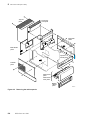
Figure A-2.
Exploded view of the printer
Figure B-1.
Inspection/check test pattern showing samples of defective printing B-1
Figure B-2.
Saturation dither pattern
Figure B-3.
Wrinkle 2 pattern showing wrinkle
xii
DECcolorwriter 1000
8-16
8-18
8-19
8-20
8-21
8-22
8-23
8-24
8-25
8-26
8-27
8-31
8-32
8-33
8-34
8-35
8-36
8-38
8-41
8-42
8-43
8-44
8-45
9-2
9-11
9-17
9-19
A-3
A-7
B-2
B-3
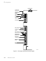
Figure C-1.
Print engine control board connector diagram
Figure C-2.
Print engine wiring diagram
Figure D-1.
Plugging the Test Pattern Generator into the printer's parallel port
C-4
C-5
D-2
Service Manual
xiii
Tables
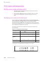
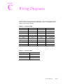
Table 1-1.
Transfer roll core sensor combinations
Table 1-2.
Tray switch sensor combinations
Table 1-3.
DECcolorwriter 1000 rear panel DIP Switches
Table 1-4.
Service mode error code summary
Table 1-5.
Physical dimensions
Table 1-6.
Printer clearances
Table 1-7.
Functional specifications
Table 1-8.
Electrical specifications
Table 1-9.
Environmental specifications
Table 2-1.
Configuration page settings for DECcolorwriter 1000 printers
Table 2-2.
Values for modifying the DEVPARAMS.PS file
Table 6-1.
Motor and solenoid resistances
Table 6-2.
Decoding the front panel display
Table 6-3.
Print engine error codes and their meanings
Table 9-1
Selecting self-test print patterns
Table 9-2
Self-check mode summary
Table 9-3
Mechanical and interrupt switch check summary
Table 9-4
Top margin adjust settings
Table 9-5
Setting thermal head temperature (based on thermal head resistance)
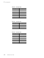
Table C-1.
Connector CN2 C-1
Connector CN3 C-1
Connector CN4 C-2
Connector CN5 C-2
Connector CN6 C-2
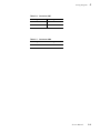
Connector CN7 C-3
Connector CN8 C-3
Test Pattern Generator DIP Switch settings for DECcolorwriter 1000 D-3
Table C-2.
Table C-3.
Table C-4.
Table C-5.
Table C-6.
Table C-7.
Table D-1.
xiv
DECcolorwriter 1000
1-5
1-6
1-9
1-11
1-12
1-12
1-13
1-14
1-15
2-11
2-21
6-8
6-18
6-19
9-3
9-4
9-9
9-12
9-15
Service Manual
xv
Chapter
1
General Information
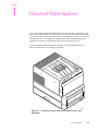
This service manual contains information useful to verify operation, troubleshoot, repair,
adjust, and maintain the DECcolorwriter 1000. The first half of this manual familiarizes
you with the printer and provides information on installing and verifying the printer and
training printer users. The latter half of the manual includes troubleshooting guides,
adjustment procedures, assembly/disassembly procedures and an FRU list.
To ensure complete understanding of the product, we recommend participation in
DECcolorwriter 1000 service training, if available.
0i
er
20
as
Ph
8699-01
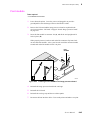
Figure 1-1. The DECcolorwriter 1000 (shown with the Lower Tray
Assembly)
Service Manual
1-1
1 General Information
DECcolorwriter 1000
DECcolorwriter 1000 is an Adobe PostScript Level 2, two page-per-minute, color
thermal-wax transfer printer. Besides PostScript, it also supports the Hewlett
Packard-Graphics Language (HP-GL) printer language. DECcolorwriter 1000 prints at
an addressability of 300 dots-per-inch. The printer features a single paper tray with an
optional lower tray assembly which gives the printer a dual tray capability. (The Lower
Tray Assembly is sometimes referred to as the second feeder.) The printer prints images
on A- and A4-size paper and transparency film with 5 mm (0.2 in.) margins.
DECcolorwriter 1000’s image processor is powered by a 16-MHz RISC processor and
features 8 Mbytes of RAM . The printer provides 17 standard printer fonts which can be
expanded to 39 fonts with the installation of an optional font module. In addition, the
DECcolorwriter 1000 supports a high-resolution 300 x 600 dots-per-inch printing mode.
For host image input, the controller also features a standard parallel port, an RS-232
serial port and a LocalTalk port.
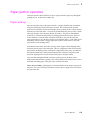
Plain-paper printing
The DECcolorwriter 1000 prints on a specially coated paper with a very smooth, even
surface, optimized for wax-transfer printing. The printers can also print on ordinary
Bond paper, using a special 4-pass plain-paper transfer roll. During printing, a special
primer coating is applied to the paper in its first pass past the thermal head. The coating
is applied only to the portions of the paper where yellow, magenta and cyan wax will be
applied in the following passes. The coating supplies a smooth, flat surface for the wax
to adhere to. Because of the extra pass required for printing on plain-paper and the fact
that the drum moves in a slower, half-step mode while placing the precoat on the paper,
plain-paper printing times are slightly longer than printing on coated paper with the
3-pass, 3-Color Transfer Roll.
1-2
DECcolorwriter 1000
General Information
1
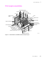
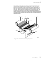
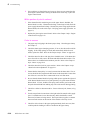
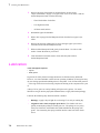
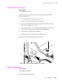
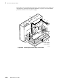
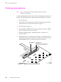
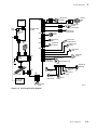
Print engine assemblies
Thermal head lift motor
I/O board
Thermal head fan
Torque limiter
Card cage
Thermal head
Image processor
board
Drum
Upper exit roller
Exit roller belt
Engine control board
Lower exit roller
Paper-feed module
Interconnect board
Feed roller
Drum motor
Drum belt
Power supply
Paper-feed motor
Transfer roll take-up motor
Pick roller
Print-feed circuit board
8699-02B
Figure 1-2. Internal features of the DECcolorwriter 1000 print engine
Service Manual
1-3
1 General Information
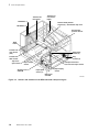
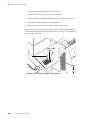
Transfer-rolllow sensor
Transfer roll
core sensor
(right)
DIP Switch 1
Thermal head position
sensors (2) -- mounted on top cover
DIP Switch 2
Drum-homeposition sensor
TEST
button
Transfer roll
core sensor
(left)
Paper-pass
sensor (2)
Transfer roll
mark sensor
Tray
sensors (3)
Top-coveropen sensor
Paper-exit sensor
Paper clamp
sensor
Aligning roller
solenoid
Front-cover-open sensor
Paper-empty
sensor
Paper-pass
sensor (1)
Paper-pick
solenoid
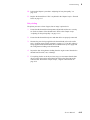
Figure 1-3. Sensors and switches on the DECcolorwriter 1000 print engine
1-4
DECcolorwriter 1000
8699-03B
General Information
1
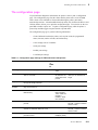
Combination sensors and their meanings
Combinations of sensors are used by the DECcolorwriter 1000 to determine the type of
transfer roll and the type of media tray installed in the printers.
Transfer roll type sensing
The combinations of the two transfer roll core sensors “tell” the print engine what type of
transfer roll is installed. The length of the cores (long or short) actuate the switches.
Long cores close the switches, turning them on.
Table 1-1. Transfer roll core sensor combinations
Left transfer
roll core
sensor
Right transfer
roll core
sensor
Transfer roll type
Closed
Open
Plain Paper Transfer Roll
Open
Open
3-Color Transfer Roll (for coated paper)
Closed
Closed
Black Transfer Roll (for coated paper)
Service Manual
1-5
1 General Information
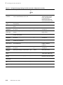
Media tray type sensing
The combinations of the three tray sensors “tell” the Phaser 200e what type of paper tray
is installed. (The print engine does not detect the type of media installed in the tray; it
only detects the particular tray used with the media.) The tray sensors are located on the
right-side interior of the paper tray slot. There are four different tray types:
n
Letter Perforated Media. This tray is used for paper and transparency film
with the tear-off perforation. This extra-long media accounts for the portion
of the media held by the drum's paper clamp during printing (and therefore
cannot be printed upon.) After tearing off the perforated end of the print, the
result is a letter-size print in which the image is printed evenly to all four of
the paper’s edges. A slide switch on the side of the media tray lets you select
either paper or transparency film.
n
Letter Plain Paper. This tray is sized for 8.5 x 11-inch plain paper. It is used
when printing with the Plain Paper Transfer Roll.
n
A4 Perforated Media. This tray is used for the metric equivalent of the
Letter-size perforated media. A slide switch on the side of the media tray lets
you select either paper or transparency film.
n
A4 Plain Paper. This tray is sized for 210 x 297-mm plain paper. It is used
when printing with the Plain Paper Transfer Roll.
Lower tray assembly. The identical sensor combination scheme is used to determine
the type of tray (referred to as the lower tray) installed in the Lower Tray Assembly.
(The Lower Tray Assembly is sometimes referred to as the second feeder.)
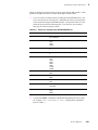
Table 1-2. Tray switch sensor combinations
1-6
Bottom
switch
Middle
switch
Top switch Tray type
Open
Closed
Open
Letter – Perforated paper
Open
Open
Closed
Letter – Perforated transparency film
Open
Closed
Closed
Letter – Plain paper
Closed
Open
Open
A4 – Perforated paper
Closed
Open
Closed
A4 – Perforated transparency film
Closed
Closed
Closed
A4 – Plain Paper
DECcolorwriter 1000
General Information
1
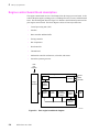
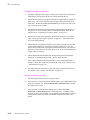
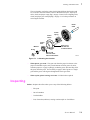
Image processor boards
ROM
Font
SIMM
RAM
SIMM
J2
J14
I/O connector
J6
J1
Interconnect board
connector
8699-05
Figure 1-4. Features of the DECcolorwriter 1000 image processor
board
Service Manual
1-7
1 General Information
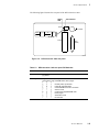
Rear panel
Connectors
The rear panel of the DECcolorwriter 1000 printer features the host interface connectors
to the printer. They include the following connectors:
n
Standard parallel
n
RS-232 serial
n
LocalTalk
The DECcolorwriter 1000 rear panel also features DIP switches to control certain
aspects of the printers’ imaging. You can also use the DIP switches for controlling the
self-tests of the printers’ image processor board. Refer to the Section 6 topic “Image
processor self-diagnostics” on page 6-30.
Health LED
A health LED indicates the status of the printer.
n
Blinking (at a steady rate): The printer is operating normally. The LED
blinks irregularly during diagnostics.
If a soft error occurs, the image processor board will operate, but in a reduced
capacity. Soft failures include failure of expansion memory SIMMs or any of
the interface ports. When a soft error occurs, the printer automatically prints
a start-up page listing the error.
n
On or Off: A hard error condition has occurred that would keep the image
processor board from operating.
TEST button
The TEST button, located at the bottom right rear corner of the printer, has two
functions:
1-8
n
Following normal power-up, pressing the TEST button for 5 seconds prints a
composite test pattern. Refer to Figure B-1 in Appendix B, Test Patterns for
a sample of the composite test pattern.
n
Pressing and holding the TEST button while you turn on the printer places
the printer in Service mode.
DECcolorwriter 1000
General Information
1
The following figure illustrate the rear panel of the DECcolorwriter 1000.
Health
LED
DIP switches
Status
LocalTalk®
1
2
3
4
Reset
*
On
Color Correction
*
Run
Off
* See Below
Parallel
Serial
(RS-232)
DECcolorwriter 1000
8699-07
Figure 1-5. DECcolorwriter 1000 rear panel
Table 1-3. DECcolorwriter 1000 rear panel DIP Switches
Switches
220e
1
(down) Normal operation
(up) Reset
2 through 4
Diagnostics modes, serial parameters fixed at 1200 baud. Vivid Blue,
Configuration page, NVRAM Reset, Demo pages
2
3
4
↓
↓
↓
Normal power-up self tests
↑
↓
↓
Fixed RS-232 parameters
↓
↑
↓
Used NVRAM-stored color correction
↑
↑
↓
Service mode
↓
↓
↑
Configuration page/NVRAM reset
↑
↓
↑
Demo pages
↓
↑
↑
Verification mode
↑
↑
↑
No self tests
Service Manual
1-9
1 General Information
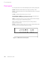
Front panel
The front panel consists of seven LEDs indicating the printer's normal operating status.
POWER: Illuminates to indicate that the power supply is generating +5 VDC.
READY: On indicates the printer is idle. Blinking indicates the printer is receiving and
processing data.
COVER: On indicates either the front or top cover is open.
TRANSFER ROLL (RIBBON): On indicates the transfer roll is low and will soon
need to be replaced. Blinking indicates the transfer roll is empty.
MEDIA: On indicates the paper tray is empty. Blinking (together with the JAM light)
indicates the wrong size paper is installed in the paper tray.
JAM: On indicates a jam has occurred inside the printer. Blinking indicates a
paper-pick error has occurred.
ERROR: On indicates a hardware engine error has occurred. Blinking indicates a data
processing error has occurred with the image processor board.
ERROR
JAM
MEDIA
RIBBON
COVER
Figure 1-6. DECcolorwriter 1000 front panel
1-10
DECcolorwriter 1000
READY
POWER
General Information
1
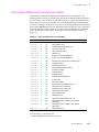
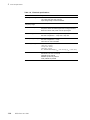
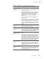
Front panel LED service mode error codes
Detected error conditions are displayed on the front panel as LED patterns. The
following table lists the service mode error codes which are displayed while the printer is
in service mode. (Service mode is explained in Chapter 9, “Checks and Adjustments.”)
These codes are more specific than the error codes displayed during normal operation
(see the previous topic “Rear panel). If an error occurs during normal operation, pressing
the rear panel TEST button causes the appropriate, and more specific, service mode error
code to be displayed on the front panel. The error codes listed below are explained in
greater detail in the Chapter 6 topic “Print engine error codes and their causes” on
page 6-19.
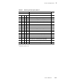
Table 1-4. Service mode error code summary
Front panel LEDs
Hex codeError
o o o o o
00
o Z
No error
o o o o o
Z Z
01
Drum position error.
o o o o Z
o Z
02
Thermal head temperature error.
o o o Z o
o Z
04
Top cover open error.
o o o Z o
Z Z
05
Front cover open error.
o o o Z Z
o Z
06
Strobe error.
o o o Z Z
Z Z
07
Engine control board RAM error.
o o Z o o
o Z
08
Engine control board ROM error.
o o Z o Z
o Z
0A
Interface error with image processor board.
o o Z Z o
Z Z
0D
Thermistor failure.
o o Z Z Z
o Z
0E
Thermal head lift error.
o o Z Z Z
Z Z
0F
Thermal head thermistor failure.
o Z o o o
o Z
10
Transfer roll empty.
o Z o o o
Z Z
11
Transfer roll low.
o Z o o Z
Z Z
12
Transfer roll jam.
o Z Z o o
o Z
18
Transfer roll feed timer error.
Z o o o o
o Z
20
Out of media.
Z o o o o
Z Z
21
Tray not installed.
Z o o o Z
o Z
22
Paper eject sensor failed to turn on.
Z o o o Z
Z Z
23
Paper-pass error / lower tray.
Z o o Z o
o Z
24
Paper-pass error / upper tray.
Z o o Z o
Z Z
25
Paper-pass sensor 2 error.
Z o o Z Z
o Z
26
Paper clamped error.
Z o o Z Z
Z Z
27
Media size error.
Z o Z o o
o Z
28
Paper eject sensor failed to turn off.
Z o Z o o
Z Z
29
Paper-pass sensor 1 failed to turn off after
paper eject.
Z o Z o Z
o Z
2A
Paper-pass sensor 2 failed to turn off after
paper eject.
Z o Z o Z
Z Z
2B
Clamp timer error.
o means LED off Z means LED on
Z means the POWER LED which is always on
Service Manual
1-11
1 General Information
Specifications
These specifications apply to the DECcolorwriter 1000 printer.
Table 1-5. Physical dimensions
Dimensions
Value
Height
28 cm. (11 ins.)
37 cm (14.5 ins.) with Lower Tray Assembly
Width:
342 cm (13.4 ins.)
Depth:
42.5 cm (16.7 ins.)
Weight:
Approximately 18 kgs (40 lbs). Print engine weight only; add
26.4 kgs (12 lbs.) for Lower Tray Assembly. Shipping weight
is not to exceed 32 kgs (70 lbs).
Table 1-6. Printer clearances
1-12
Clearances
Value
Top:
45.7 cm (18 ins.)
Left:
10.2 cm (4 ins.)
Right:
10.2 cm (4 ins.)
Front:
Unrestricted to replace trays and transfer rolls
Rear:
10.2 cm (4 ins.)
Bottom:
No obstruction under printer that could block its cooling
vents.
Mounting surface
flatness:
Within 5 degrees of horizontal with all four feet in contact
with the surface.
DECcolorwriter 1000
General Information
1
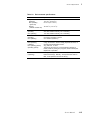
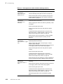
Table 1-7. Functional specifications
Characteristic
Specification
Printing process
Sequential surface thermal transfer printing (thermal-wax
transfer).
Transfer rolls
Wax-impregnated transfer rolls. The printer automatically
senses the transfer roll type by the coding on the leading
edge of the yellow band.
3-Color Transfer Roll features sequential bands of yellow,
cyan, and magenta; 342 prints per roll.
A 4-pass Plain Paper Transfer Roll features sequential bands
of precoat, yellow, magenta and cyan; 214 prints per roll.
Black Transfer Roll features all black panels; 880 prints
per roll.
The printer automatically senses the transfer roll type by the
size of the transfer roll cores.
Addressability
300 dots-per-inch (horizontal and vertical).
Engine printing speed
The time it takes from paper loading to paper ejecting a print:
3-Color transfer roll: about 30 seconds per print.
ColorCoat transfer roll: about 40 seconds per print.
Print times do not include image processing time by the
image processor which varies due to image complexity.
Minimum printing
margins
Perforated paper:
A- and A4-size: all sides, 5 mm (0.2 ins.).
Non-perforated paper
A- and A4-size: all sides, 5 mm (0.2 ins.) except the bottom,
which is 21 mm (0.8 ins.)
Service Manual
1-13
1 General Information
Table 1-8. Electrical specifications
Characteristic
Specification
Primary line voltages
87 to 128 VAC (115 VAC nominal)
174 to 250 VAC (220 VAC nominal)
Input voltage range is switch-selectable.
Primary voltage
frequency range
47 to 63 Hz
Power consumption
235 watts at idle. (800 BTUs/hour) – Power consumption for
the printer will be somewhat higher due to image processor
electronics which draw power from the print engine.
Current rating
115 VAC configuration – 7 amp max./1 amp min.
220 VAC configuration – 7 amp max./1 amp min.
1-14
Primary voltage fusing
115 VAC configuration – 5 amp
220 VAC configuration – 5 amp
Fuses are not user-accessible.
Secondary voltages
+5V (4.95 ~ 5.05 V) — 10 A maximum
+12 V (11.2 ~ 12.6 V)
-12 V (115.5 ~ 12.5V)
+24 V (24.4 ~ 24.7V)
VH – thermal head voltage (V high – 26 ~ 27.4 V), (Vlow – 10.6 ~ 11.0)
RF emissions
Both 115 and 220 VAC-configured instruments pass these
standards: FCC Part 15 Class B
VDE 0871/6.78 Class B
EN55022 (CISPR 22) Class B
VCCI (CISPR 22) Class B
DECcolorwriter 1000
General Information
1
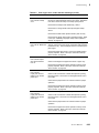
Table 1-9. Environmental specifications
Characteristic
Temperature
Operating
Non-operating
(power off)
Storage
(without transfer roll)
Specification
15 to 30 C° (59 to 86° F)
0 to 40° C (32° to 104°F)
-20 to 60° C (-4 to 140° F)
Humidity
Operating
Non-operating
20 to 80% relative humidity, non-condensing
10 to 90% relative humidity, non-condensing
Altitude
Operating
Non-operating
0 to 4570 m (15,000 ft.) at 25°C
0 to 15200 m (50,000 ft.)
Vibration/shock
Non-Operating
(vibration)
Non-operating (shock)
Operating (shock)
Acoustic Noise
(operating)
0.75g, 25 minutes in three mutually perpendicular axes, no
resonant frequencies below 25 Hz.
30 g, half sine, 11 msec.
The printer may have any corner raised and dropped 2
inches, while no printing is in progress, without subsequent
impairment of operation.
Printing - sound power less than 6.6 Bels, sound pressure
less than 50 db (A). Standby - sound power less than 6.3
Bels, sound pressure less than 46 db (A)..
Service Manual
1-15
1 General Information
Regulatory specifications
The DECcolorwriter 1000 is a recognized component in conformance with the following
regulatory standards:
1-16
n
The packaged product meets National Safe Transit Committee Test
Procedures.
n
UL 1950 Information Processing & Business Equipment.
n
CSA C22.2 No. 950 Safety of Information Technology Equipment, Including
electrical Business Equipment.
n
IEC 950 (1991) Second Edition; EN60950 Information Processing &
Business Equipment.
n
EC: EN60950 Safety of Information Technology Equipment including
Electrical Business Equipment.
n
EC: EN55022 Limits and methods of measurement of radio interference
characteristics of Information Technology Equipment.
n
Vfg 243 Radio Interference suppression of Radio Frequency Equipment for
Industrial, Scientific, Medical (ISM) and similar purposes and Equipment
used in Information Processing Systems; General License.
n
VDE 0871/6.78 (Class B) Radio Frequency Interference Suppression of
Radio Frequency Equipment for Industrial, Scientific, Medical (ISM) and
Similar Purposes.
n
FCC Class B (for 115 VAC equipment).
DECcolorwriter 1000
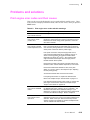
Chapter
2
Installing the Printer and
Drivers
This chapter discusses installing the printer and its drivers.
Installation consists of three main functions detailed in this
and the next two chapters of this manual:
n
Chapter 2 “Installing the Printer and Drivers.” The first portion of installation
instructions, this chapter, consists of five basic processes:
n
Pre-installation interview. This is a phone interview to verify that the customer
is ready for the printer. The interview verifies that the customer has a suitable
place for the printer with the proper environment. The call also verifies that
any assistance, such as network system administration, will be available for the
scheduled installation and that all necessary cables will be available.
n
Unpacking. This is the procedure for taking the printer out of its shipping box.
n
Testing. This checks that the printer works properly prior to connecting it to a
host computer.
n
Cabling and configuring. This discusses setting up the printer for
communicating to the appropriate host computers.
n
Loading drivers. This covers installing software on the host computers and
configuring the host applications to drive the printer.
Following these steps, proceed to Chapter 3 and then Chapter 4.
n
Chapter 3 “Verifying the Printer and Its Hosts” explains how to verify that the
printer, the host driver and the connection between them function correctly.
n
Chapter 4 “Key Operator Training” gives a procedure for training the user to
use and care for the printer.
Service Manual
2-1
2 Installing the Printer and Drivers
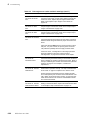
Pre-install questions for customers
Prior to installing a DECcolorwriter 1000, you should contact the customer and verify
that he or she has prepared an appropriate location for the printer. You will also want to
ensure that you have all the information you need to install the printer at the customer's
site.
Ask the customer the following:
Customer's name _____________________________________________________
Address ____________________________________________________________
Phone number _______________________________________________________
2-2
n
What type of computers will be networked to the printer?
o PC ______________
o Macintosh___________
o UNIX____________
o other _______________
n
Which type of host-to-printer connection will be used:
o serial
o parallel
o LocalTalk
n
In the event that the printer is to be installed into a network environment, will
a network administrator be available to help in assigning network names and
addresses for the printer?
Administrator's name ____________________________
Phone Number _________________________________
n
What software application packages will be used with the printer? (Some
applications require special printing utility files.)
_____________________________________________
n
Will the application(s) and sample files be available at the time of the
installation to send test files to the printer? ___________
n
Does the customer have the appropriate power outlet available? The printer's
AC power input is set for these voltages:
110 VAC (87 to 128 VAC)
220 VAC (174 to 250 VAC)
If necessary, refer to the later topic “Selecting the AC input voltage.”
n
Did the customer order the correct model?
_______ U.S.
_______ European
_______ United Kingdom
_______ Australian
_______ Italian
_______ Israeli = UK + power cord
_______ Swiss
DECcolorwriter 1000
Installing the Printer and Drivers
n
2
Customers must provide the particular interface cable or network adapter they
need to use with the printer.
n
10 ft. parallel cable
n
Serial, 25-pin to 25-pin, 3 m (10 ft.), null modem
n
Serial, 9-pin to 25-pin, 3 m (10 ft.), null modem
For AppleTalk installations, customers must provide the appropriate network
adapter to the printer's 9-pin circular LocalTalk connector. Customers can
obtain an adapter from their dealer.
The printer requires the following environmental conditions:
o
o
n
Temperature: 15 to 35 C (59 to 95 F)
n
Humidity: 20 to 80% relative humidity, non-condensing
n
Power: 110 VAC or 220 VAC. The printer requires 7 amps of current at full
load.
n
Clearances: A space measuring 46 cm wide by 92 cm deep by 76 cm high (18
ins. wide by 36 ins. deep by 30 ins. high). The space in front of the printer
accounts for enough clearance to install the paper tray. The extra height is to
install the transfer roll.
n
Weight support: 20 kgs (45 lbs.) minimum.
Service Manual
2-3
2 Installing the Printer and Drivers
Driver software must be installed on the host computer to use the printer to its fullest
potential. A host computer must meet the following conditions:
Mac
n
Mac II, Performa, Centris or Quadra
n
Operating System 6.0.7 or later
n
4 Mbytes RAM
PC
n
IBM AT, PS/2 or compatible, with a 386 or later CPU, a 5.25- or 3.5-inch
floppy drive, and a hard disk drive, 2 Mbytes RAM
DOS system
DOS 3.1 or later
An application that supports color PostScript or HP-GL
Windows systems
Windows 3.1
2 Mbytes of hard disk space
Workstation
2-4
n
UNIX workstations: The X Windows System,
SUN workstations: OpenWindows recommended
n
750 kbyte hard disk space for files
DECcolorwriter 1000
Installing the Printer and Drivers
2
Unpacking
Inventory for the DECcolorwriter 1000 printer
n
Printer
n
Paper tray
n
Power cord
n
Getting Started folder
n
Cleaning kit
n
Supplies information sheet
n
Transfer roll
n
Paper
n
Transparencies
n
User manual
n
Printer drivers and utilities reference manual
n
Printing utilities and driver diskettes
n
Optional Lower Tray Assembly (with paper tray)
Service Manual
2-5
2 Installing the Printer and Drivers
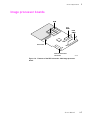
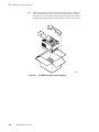
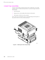
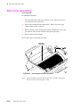
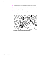
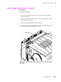
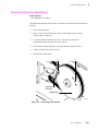
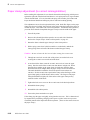
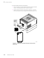
Note
Prior to repacking a printer, ensure that the paper clamp is positioned
under the bail rollers. This prevents the bail rollers from “denting”
the soft material of the drum. In normal operation, the paper clamp is
automatically parked in this position when the printer is not printing.
8699-69
Figure 2-1. The DECcolorwriter 1000 packaging
2-6
DECcolorwriter 1000
2
Installing the Printer and Drivers
Setting up the printer
Installing the printer is explained in detail in either the DECcolorwriter 1000 User
Manual. The following is a brief list of the steps you follow to unpack and set up the
printer.
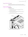
1.
Place the printer in its working location.
2.
Open the top cover and remove the shipping pad that protects the printhead.
Also remove the shipping blocks on either side of the drum.
3.
Install a transfer roll.
4.
Close the top cover.
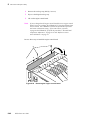
5.
Load the paper tray with paper. Press the paper down in the tray until the
spring plate latches to the bottom of the tray. Make sure the printed side is up
and the perforated edge of the paper faces forward.
6.
Set the media select switch on the side of the tray to PAPER. (Set the lever to
TRANSPARENCY if you are loading the tray with transparency film.)
Caution When moving a printer featuring the Lower Tray Assembly, be sure
to grasp the Lower Tray Assembly by its hand holds on both sides to
lift it and the printer together. Carry the printer by carrying the
Lower Tray Assembly. Failure to do so may damage the printer.
7.
Install the paper tray in the printer. If also purchased, install the Lower Tray
Assembly underneath the printer.
8.
AC voltage selection: Locate the AC voltage select switch on the right side
of the printer. Ensure that it is set to the correct voltage for the customer's
installation (either 115 VAC or 220 VAC).
9.
Ensure that the power switch is off.
10. Plug the printer's power cord into the printer's AC receptacle. Plug the other
end into an appropriate AC power outlet.
11. Rear panel switches: Ensure that all the rear panel DIP switches are in the
down position.
12. Turn on the printer. It will execute a power-up self-test and then it prints a
startup page. If it fails its self-test or doesn't print a startup page, refer to
Chapter 6, “Troubleshooting.”
13. Turn off the printer.
Service Manual
2-7
2 Installing the Printer and Drivers
Cabling the printer
Note
Carry spare serial and parallel cables. You can use them if you
encounter a defective cable or as an alternate means of testing the
printer-to-host communications.
This topic explains making a hardware connection between a DECcolorwriter 1000 and
its host computer, setting the communication parameters for the printer's serial and
parallel ports to be compatible with the user's host computer and driver installation. This
topic is divided into three main parts: Macintosh, PC, and workstation.
Connecting the printer to a Macintosh
A direct connection between the printer and a Macintosh would be through the printer's
LocalTalk port. A networked connection for a Macintosh will most likely be either a
LocalTalk network or an Ethernet network.
LocalTalk connection to a Macintosh
1.
Turn off the printer. LocalTalk protocol requires that you attach the
LocalTalk cable with the printer powered off.
2.
For a direct connection, attach the interface cable or adapter to the host
computer's LocalTalk port. (The port has a printer icon printed next to it.)
Attach the other end to the printer’s LocalTalk port.
For a LocalTalk network connection, attach the network adapter to the
printer's LocalTalk port.
3.
Turn on the printer and the computer.
Connecting the printer to a PC
Direct connection to a PC
2-8
1.
Turn off the printer. Turn off the host computer.
2.
Attach the parallel interface cable to the host computer. Attach the other end
to the printer. Alternatively, attach the serial cable to the host computer's
serial port. Attach the other end to the printer's serial port.
3.
Turn on the printer and the computer.
DECcolorwriter 1000
Installing the Printer and Drivers
2
Connecting the printer to a workstation
Direct connection to a workstation
1.
Turn off the printer. Turn off the host computer.
2.
Attach the parallel interface cable to the workstation. Attach the other end to
the printer. Alternatively, attach the serial cable to the workstation's serial
port. Attach the other end to the printer's serial port.
3.
Turn on the printer and the computer.
Service Manual
2-9
2 Installing the Printer and Drivers
Turning on the printer
The startup page
When you turn on a DECcolorwriter 1000 printer, it executes a series of self-tests to
determine if there are any problems with the PostScript interface. After running
self-tests, the printer prints a startup page if it has not been disabled. (The factory default
condition is to have the startup page enabled.) After running self-tests and printing the
startup page, the printer is ready for operation. A downloadable PostScript utility, found
on the Drivers and Utilities diskette, allows you to enable or disable the startup page.
The startup page provides you with valuable information about the printer:
n
Fonts
n
Ports (Serial, Parallel, LocalTalk, Ethernet)
n
Printer name
n
Color corrections and print quality mode
n
Pages Printed
n
RAM installed
n
Image processor version firmware
n
Adobe PostScript version software
n
Type of transfer roll loaded
If the printer detects a non-fatal error at power-up, the startup page prints with an error
message shown in red. This is true, even if the startup page has been disabled. The
printer will still force a print to report the error.
Message
Serial, Parallel, LocalTalk, EtherTalk, or
SCSI Port failed
Description
The named port is not working. The other
ports can still be used.
DRAM SIMM x failed
The memory SIMM x is not working. In this
message, x indicates the number of the
SIMM that failed (1 or 2). Since the printer’s
base memory is still working, the printer can
still be used, but large images may not print,
special imaging features may not work and
throughput may suffer.
If metric media is not being used and the page count in the image processor is equal to 6,
7, or 8, then a registration page will print out after the startup page.
2-10
DECcolorwriter 1000
Installing the Printer and Drivers
2
The configuration page
To provide further diagnostic information, the printer is able to print a configuration
page. The configuration page lists the values that the printer stores in its NVRAM.
These values can be informative when troubleshooting the printer, particularly
networked operations. A downloadable PostScript utility file, found on the Drivers and
Utilities diskette, allows you to print the configuration page. You can also use the rear
panel DIP switches to print one. To print a configuration page, while the printer is
powered-up and idle toggle rear panel Switch 4 up and down.
The configuration page gives you the following information:
n
General information about the printer, such as print count, the programmed
name, timeouts, number of fonts, and total memory
n
Color settings such as Vivid Blue.
n
Serial port settings
n
Parallel port settings
n
LocalTalk port settings
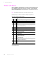
Table 2-1. Configuration page settings for DECcolorwriter 1000 printers
Parameter
Description
Saved
in
NVRA
M
Default
Limits or alternate choices
Printer type
The name of the product
yes
DECcolorwriter
1000
Printer name
The current name of the printer as
seen on a network
yes
<printer name>
the default is the
same name of the
product
Pages printed
Total number of prints processed
through the image processor
yes
0
Start page
enabled
Indicates if the printer prints a startup
page upon power-up
yes
No
Yes or no
Fonts in ROM
Number of font stored in the printers
ROM memory
17 in
DECcolorwriter
1000, unless font
module is
installed, which
then totals 39
17 or 39
Job Timeout
Amount of time a job can take to
process
yes
0 seconds
Any value denoted in
seconds; 0 means unlimited
amount of time
Wait Timeout
Amount of time the image processor
will wait for additional data from a host
yes
40 seconds
Any value denoted in
seconds; 0 means unlimited
amount of time
RAM memory
Total amount of RAM on the image
processor board
10 MBytes (220i)
8 MBytes (220e)
14 Mbytes (220i)
Any name defined by the
user up to 31 characters in
length
Service Manual
2-11
2 Installing the Printer and Drivers
Table 2-1. Configuration page settings for DECcolorwriter 1000 printers (cont'd.)
Parameter
Description
Saved
in
NVRA
M
Default
Limits or alternate choices
Color
Correction
Indicates the type of color adjustments
used to simulate different color uses
yes
None
User Defined, Vivid Blue,
Simulate Display, SWOP
Press, Euroscale Press,
Commercial Press,
Monochrome, Raw RGB
Colors, Raw CMYK Colors
Print quality
mode
Indicates the quality mode to use for
image printing
yes
Standard
Enhanced, Hi-Resolution
Transfer roll
Type of transfer roll installed in the
printer
no
3 color
4 pass, 1 color (black)
LocalTalk port
interpreter
Indicates the type of interpreter in use
at the port
yes
PostScript Level
2
Not installed, Disabled,
<interpreter>
LocalTalk
printer type
Indicates the type of printer installed at
the port
yes
LaserWriter
Any string 32 characters in
length or less
LocalTalk node
Indicates the LocalTalk network node
number of the printer
no
0
Any integer 0 through 254
Parallel port
interpreter
Indicates the type of interpreters in use
at the port
yes
PostScript Level
2
Not installed, Disabled,
<interpreter>
Parallel port
Encoding
Indicates the type of data encoding the
parallel port is inspecting
yes
ASCII
Binary, Raw, TBCP
Parallel port
back channel
The device used for standard output
and standard error
yes
Serial
Serial B, Serial C, ... , or
Parallel, Parallel B,
Parallel C, ...
Serial port
interpreter
Indicates the type of interpreters in use
at the port
yes
PostScript Level
2
Not installed, Disabled,
<interpreter>
Serial port
encoding
Data byte encoding for communication yes
ASCII
Binary, Raw, TBCP
Serial port
speed
Baud rate
yes
9600
38400 (printer dependant),
19200, 9600, 4800, 2400
Serial port
flagging
Hardware or software flagging
yes
XonXoff
DTR, DTR low, Etx Ack,
Robust Xon Xoff, Xon Xoff2
Serial port
check parity
Parity check encoding method
yes
None
Space, Even, Odd, Mark
Serial port data
bits
Bits used to encode a data byte
yes
8
7
Serial port stop
bits
Number of stop bits
yes
1
2
2-12
DECcolorwriter 1000
Installing the Printer and Drivers
2
Driver and communication setup
Loading the Macintosh driver
Note
Turn off any anti-virus software running on the Macintosh before
installing the Digital software.
DECcolorwriter 1000 printer uses the Adobe PostScript Level 2 language. To take
advantage of the Level 2 features, the printer features a DECcolorwriter 1000-specific
driver which appears in the Chooser along with the LaserWriter 7.0.x driver. The driver
includes special paper sizes for each printer and color correction adjustment options.
Refer to the DECcolorwriter 1000 Drivers and Utilities Printing Reference for more
details.
To install the DECcolorwriter 1000 driver with system 6.0.7 or higher
1.
Place the DECcolorwriter 1000 Drivers and Utilities diskette (Macintosh)
into the disk drive.
2.
Double-click on the Installer icon and click OK at the introductory screen.
3.
In the Easy Install window, click the Install button.
4.
Click the Restart button in the dialog box that appears.
5.
Select the driver’s icon and the printer in the Chooser.
Note
Macintosh computers on a network should have a minimum of system
software 6.0.7 installed.
LaserWriter 7.0.x and its support files (Laser Prep, Backgrounder, and PrintMonitor)
are required to use the DECcolorwriter 1000 driver and to print in the background. The
Installer automatically copies these files to your hard disk drive if you are using system
6.0.7 or higher.
Service Manual
2-13
2 Installing the Printer and Drivers
Installing the custom driver for Windows 3.1
The Windows driver is a Windows PostScript driver customized for a DECcolorwriter
1000. These instructions assume a basic familiarity with Windows operation and
terminology. For additional information about Windows, refer to your Microsoft
Windows documentation.
1.
Insert the Windows 3.1 Printer Driver diskette into your computer’s disk
drive, for example, drive B:.
2.
Start Windows.
3.
Open the Control Panel. Double-click the Printers icon; the Printers
dialog box appears.
4.
Choose the Add>> button.
5.
In the List of Printers, select Install Unlisted or Updated Printer.
6.
Choose the Install button.
7.
Type in the drive the PC diskette is in, for example drive B:, and choose the
OK button.
8.
Select your printer and choose OK.
9.
The driver software you need is automatically installed.
10. Continue with the later topic “Configuring the custom Windows printer
driver” on page 2-14.
Configuring the custom Windows printer driver
2-14
1.
The Printers dialog box should still be displayed; if not, double-click the
Printers icon in the Control Panel.
2.
Choose your printer from the list of installed printers.
3.
Choose the Set As Default Printer button if you want to select your printer
as the default.
4.
Choose the Connect button; the Connect dialog box appears.
DECcolorwriter 1000
Installing the Printer and Drivers
5.
2
Select the port the printer is connected to. Your printer is connected to your
computer through one of the computer's communications ports. You need to
tell the driver which port your printer uses so that the driver can print your
documents.
The two main types of communications ports are parallel ports and serial
ports; your computer may have one or more of each. Generally, your printer
is connected through LPT1: if it is connected to a parallel port, or through
COM1: if it is connected to a serial port. If you have multiple ports, your
printer may be connected to another, such as COM2:.
Note
The printer’s configuration page contains the information you need to
setup the printer’s port.
n
For a parallel port set-up in Windows: Select your parallel (LPT) port in the
list.
n
For a serial port set-up in Windows: Select your serial (COM) port in the
list. Choose the Settings button to see the Settings dialog box. Fill in each
item according to your configuration, then choose the OK button. Refer to
your Windows documentation for details, or ask your network administrator
for help.
n
For a network port set-up in Windows: Select your network (LPT or COM)
port in the list. Choose the Network button to see the Printers-Network
Connections dialog box. Fill in each item according to your configuration,
then choose the OK button. Refer to your Windows documentation for details,
or ask your network administrator for help.
Other communications ports may include EPT: (an interface for the IBM
Page-Printer, which requires the installation of a special card in your
computer), and LPT1.OS2 and LPT2.OS2, which Windows may require if
you are using certain spoolers or other add-on software programs. The port
FILE: lets you write a PostScript document to a file instead of to the printer.
For more information about communication ports, refer to your Windows
documentation.
6.
Set the Timeouts. These options regulate your computer’s communications
with its printer ports.
n
Device Not Selected: (For parallel (LPT) ports only.) Type a value of 0, or a
value between 15 and 999, in this text box to change the number of seconds
Windows waits before notifying you that a printer is off-line. The default is
15 seconds.
n
Transmission Retry: Type a value between 45 and 850 in this text box to
change the number of seconds Windows waits after a print job has begun
sending characters to the printer, before sending an Alert message that the
printer is no longer accepting data. The default setting is 45 seconds. When
using the Print Manager with a shared printer, you should set this option to a
larger value, such as 600 (10 minutes) to avoid the Alert message when
printing multiple-page documents.
Service Manual
2-15
2 Installing the Printer and Drivers
7.
Choose the OK button to return to the Printers dialog box, then choose the
Setup button. A dialog box appears with the name of the printer you selected
across the top. Use this dialog box to select paper source, paper size, and
image orientation.
8.
Choose the Options button to see the Options dialog box. Make sure that the
Color box is checked to print in color.
9.
From the Options dialog box, choose the Advanced button to see the
Advanced Options dialog box. Make sure that the Use PostScript Level 2
Features check box is checked on.
This option affects the print time of bitmapped (raster) images by improving
the image transfer time from the computer to the printer, and by improving
the image processing time in the printer. This option is only available to
applications that use this custom driver with DECcolorwriter 1000 printer.
When this box is checked, the Compress Bitmaps option is unavailable
(grayed out). Choose the OK button to return to the Options dialog box.
10. In the Options dialog box, choose the Printer Features button to see the
DECcolorwriter 1000 Printer Features dialog box. Make color correction
and media type selections as desired. Choose the OK button to return to the
Options dialog box.
11. Choose the OK button to return to the dialog box that lists your printer's
name across the top.
12. Choose the OK button to return to the Printers dialog box.
13. Choose the Close button.
2-16
DECcolorwriter 1000
Installing the Printer and Drivers
2
Updating the standard Microsoft Windows PostScript driver
If a customer prefers to use the standard Microsoft Windows PostScript printer driver
instead of the custom driver for Windows, follow these instructions. This update
procedure provides printer page size information for applications within Windows using
the standard driver. However, color adjustments and other PostScript Level 2 features
are available only with the custom Windows 3.1 driver and are not supported by the
standard driver.
These instructions assume a basic familiarity with Windows operation and terminology.
For additional information about Windows, refer to your Microsoft Windows
documentation.
Update procedure
1.
Start Windows.
2.
Open the Control Panel.
3.
Double–click on the Printers icon.
4.
Choose the Add>> button; a list of printers is displayed.
Highlight the DECcolorwriter 1000 printer.
5.
Select Install Unlisted or Updated Printer.
6.
Choose the Install button.
7.
When prompted, insert the provided standard Windows 3.1 Printer Driver
diskette into your computer’s disk drive. Conndect to the appropriate floppy
drive and the directory \WPD. Choose your printer and then click the OK
button. When asked to insert a diskette with the updated PSCRIPT.DRV file,
enter system as the location so that the current PSCRIPT.DRV file is used.
Installing the printer driver for OS/2 Version 2
Under OS/2 Version 2.0 printing is managed through printer object icons. Object icons
represent a printer setup, and are associated with a port, a driver, and a queue, if
appropriate. These object icons replace the earlier Print Manager functions. Normally, a
printer object icon is installed during the initial OS/2 2.0 installation. A single printer
object on the desktop may represent more than one printer. A printer object on the
desktop is a “generic” object that can be configured to point to any printer by changing
settings in the settings notebook for this object. You may not have more than one printer
object pointing to the same I/O Port. Port designations for each printer object must be
unique. Before new printers are installed, existing printer object assignments must be
changed.
Note
IBM suggests that printer objects be named to represent available
printer ports rather than printer names or printer drivers. This avoids
the confusion of a specific printer name being associated with an
object that is using a driver for a different printer.
Service Manual
2-17
2 Installing the Printer and Drivers
Check existing printer object port assignments before installing a new printer to be sure
there is no conflict. Once you are familiar with existing printer objects (drivers and ports
associated with these objects) you can install a new printer.
In the procedure below the printer remains associated with LPT1, and you will set up a
new printer object for LPT2. Following are the steps to create the LPT2 PRINTER
object:
1.
Check all existing printer objects to be sure that they do not point to LPT2.
Make any necessary changes to the settings for these printer objects.
2.
Locate the original OS/2 Print Driver Diskettes (1-5).
3.
Find and open the TEMPLATES folder and locate the Printer Template.
4.
Using the mouse, point to the Printer Template, hold down the right mouse
button, and drag the object onto the desktop and release the mouse button.
5.
The Create a Printer dialogue box will be displayed. In the name field,
type: LPT2 PRINTER. This is the only opportunity to assign this name and
it cannot be changed. The first 8 characters (except spaces) will display in all
printer selection menus, so the printer will be listed as LPT2PRIN.
6.
Scroll through the printer drivers listed to locate the proper printer driver
name. If it is listed, select it, otherwise, point the cursor to any other driver
listed and click the right mouse button. Click Install from the menu options.
7.
In the Install New Printer Driver dialogue box, set the directory to B: and
insert the Printer Diskette #1 in drive B:. Click on Refresh. The system
searches the diskette for driver groups and prompts you to stop the search or
continue. When the PostScript driver (PSCRPT.DRV) appears, stop the
search.
8.
At this point, a list of possible PostScript printers are displayed for your
selection. Using the scroll bars, move down through the alphabetical listing
until you find the selection PSCRIPT. DECcolorwriter 1000. Click on the
correct printer name and then click on Install. The system will install your
printer driver. Click OK.
9.
Close the Install New Printer Driver dialogue box. Before leaving the
Create a Printer dialogue box, adjust the printer port timeout setting.
Double-click on the port you have selected, in this example, LPT2. Change
the timeout to 180 seconds. Then click OK.
10. To create the new printer object on the desktop, click on Create. A new
printer driver object is placed on your desktop. Confirm and adjust the
settings for this printer driver by launching an application program and
performing the following steps.
a. Bring up the Settings Notebook by clicking the right mouse button on
LPT2 PRINTER. Click on the arrow to the right of OPEN, click on
SETTINGS.
2-18
DECcolorwriter 1000
Installing the Printer and Drivers
2
b. Select the Printer Driver Tab. Confirm that the DECcolorwriter 1000 is
selected (highlighted). Double-click on the DECcolorwriter 1000 driver
to configure the Printer Properties. This is where you can define
printer paper sizes and orientation. These settings can be adjusted from
within software applications as well. To get started, set Forms to
Legal-size paper. This is the recommended setting. Next, select Device
Defaults, set Form to Legal and set Orientation to Landscape. One of
the most likely causes of printer errors is that the document and device
defaults do not match.
c. Select Options and make sure that it is set to DECcolorwriter 1000. If
not, repeat the previous steps. While in this screen, set Job and Wait to
0, if they aren't already. Select the Output Tab. Ensure that the proper
port is selected.
d. Select the Queue Options Tab. Activate a check for both Printer
Specific Format and Job Dialog Before Print. Return to the Settings
Notebook and close it.
e. If LPT2 PRINTER is not the only printer object on the desktop, then
you may want to make it the default printer before opening a software
application. To do so, point the cursor to the LPT2 PRINTER object,
click the right mouse button, click on Set Default, and select LPT2
PRINTER.
Service Manual
2-19
2 Installing the Printer and Drivers
Configuring the printer's serial port for a PC
Use the PostScript command file DEVPARAM.PS (also located on the Utilities diskette)
to modify the printer’s serial port settings.
To modify DEVPARAM.PS you should be familiar with the PostScript setdevparams
command. This file lets you configure the printer's serial port. The following example
sets flow control to Xon/Xoff, parity to none, data bits to 8, stop bits to 2 and the baud
rate to 9600. In the example below, the changes are persistent across print jobs and
across power cycles; they remain in effect until specifically changed again.
Note
CTRL-D is the ASCII End-Of-Text (EOT) character.
DECcolorwriter 1000
CTRL-D
systemdict/languagelevel known{languagelevel 2 eq
{true}{false}ifelse}{false}ifelse
{
(%Serial_NV%) <</Password ()
/FlowControl /XonXoff
/Parity
/None
/DataBits 8
/StopBits 2
/Baud 9600 >> setdevparams
) if
CTRL-D
2-20
DECcolorwriter 1000
Installing the Printer and Drivers
2
When you change the settings for the serial port, the baud rate DIP Switch 7 on the
printer's back panel must be down before the changes will take effect.
1.
Use a text editor or word processor to modify the DEVPARAMS.PS file. (Be
sure to save the file as a text-only file.) Substitute the values you want for the
values used in the sample DEVPARAM.PS file. The possible values for each
parameter are listed in the following table. The values are case-sensitive;
they must be entered exactly as shown.
Table 2-2. Values for modifying the DEVPARAMS.PS file
Parameter key
Allowed Values
Types
FlowControl
XonXoff (software)
Dtr (hardware)
string
Parity
Even
Odd
None
Space
string
DataBits
7
8
integer
StopBits
1
2
integer
Baud
300
600
1200
2400
4800
9600
19200
38400
integer
Enabled
true
false
boolean
CheckParity
true
false
boolean
On
true
false
boolean
Interpreter
PostScript
HP7475A
string
Protocol
Normal
Raw
Binary
string
2.
Use the DOS COPY command to send the DEVPARAM.PS file to the printer;
for example: COPY DEVPARAM.PS COM1: (Substitute the appropriate
port for COM1:.)
Service Manual
2-21
2 Installing the Printer and Drivers
Using printcap to configure a Unix workstation for the printer's
serial port
The printcap file configures the workstation's lpr queues. The file is usually found in
the workstation's /etc directory. The printer's rear panel switch settings should all be
down. Use a null modem cable, since the printer is set up as a DTE device. For this
example, the printer's serial port settings are as follows:
Speed:
Flagging:
Data Bits:
Parity:
9600
Software (XON/XOFF)
8
Ignore
To set up a printcap entry, perform the following steps:
1.
Make a backup copy of the /etc/printcap file.
2.
Add to the printcap file a new print queue name and set the port parameters
as needed. Add the following to the printcap file:
px:\
:br#9600:rw:\
:fc#00000374:fs#00000003:\
:xc#0:xs#0040060:\
:mx#0:sf:sh:\
:sd=/var/spool/px:\
:if=/var/spool/px/if:\
:lp=/dev/ttya:
px may be changed to whatever unique printer name you choose. The device
driver name in lp may be different depending upon which serial port the
printer is connected to and the device driver naming scheme for the
workstation.
3.
Create a directory called /var/spool/px and create a file in the directory called
if. The content of the file should look like this:
#!/bin/sh
/bin/cat
4.
Give the if file executable permission:
chmod +x if
If communication to the serial port uses 7 data bits, the value for xs changes
as follows. All other setup parameters remain the same.
2-22
DECcolorwriter 1000
Installing the Printer and Drivers
2
px:\
:br#9600:rw:\
:fc#00000374:fs#00000003:\
:xc#0:xs#0040040:\
:mx#0:sf:sh:\
:sd=/var/spool/px:\
:if=/var/spool/px/if:\
:lp=/dev/ttya:
5.
To print a PostScript file type:
lpr -Ppx filename
Service Manual
2-23
2 Installing the Printer and Drivers
2-24
DECcolorwriter 1000
Chapter
3
Verifying the Printer and
Host Connections
In this chapter, you verify that the host computer can send files to the printer. This
chapter assumes that the printer and the printer drivers have been properly installed as
explained in the previous chapter “Installing the Printer and Drivers.”
Verifying printing to a Macintosh
Selecting the printer via the Chooser
This procedure applies to both operating system version 6.0.7 (and higher) and system
7.0 (and higher).
1.
Turn on the printer and the Macintosh, if they are turned off.
2.
With the mouse, click and hold on the Macintosh's Apple menu (in the
upper-left corner of the screen). Select the Chooser from the Apple's
pull-down menu.
3.
The Chooser dialog box is now displayed on the screen. On the left side of
the dialog box are icons representing the printer drivers installed on the
Macintosh. Select the driver icon DECcolorwriter 1000 by clicking on it
once. If the host and the printer are a part of a zone, you should first select the
printer driver and then pick the zone that the printer resides in.
4.
Displayed on the right side of the dialog box are a list of printers that the
selected driver will print to. Select the newly installed printer
DECcolorwriter 1000. (If, for example, a DECcolorwriter 1000 is already
on the network with the name DECcolorwriter 1000, then the newly
installed printer will be named DECcolorwriter 10001.)
5.
Displayed on the bottom of the dialog box is the background printing option.
Click the OFF button to turn it off. (If desired, this can be turned back on
after the printer verification.)
6.
Close the Chooser by clicking on the small box in the upper-left corner of the
dialog box. The DECcolorwriter 1000 is now your chosen printer.
You have now verified that the printer is on the network and is communicating with the
Macintosh.
Service Manual
3-1
3 Verifying the Printer and Host Connections
If you do not see the printer listed in the dialog box, then the printer is not
communicating with the Macintosh. Check the printer's cable connection to the network.
Also check the printer to see if its rear panel health LED is blinking. Ensure that the
correct network is selected, in the event that the Macintosh is connected to more than one
network (such as both LocalTalk and Ethernet). Refer to Chapter 6, “Troubleshooting”
for more information about networks. More troubleshooting tips are included in the
reference manual DECcolorwriter 1000 Drivers and Utilities Printing Reference.
Print the directory from Macintosh
1.
Make sure that you have an open window displayed on the screen (such as the
hard disk drive's window).
2.
At the Macintosh desktop, click and hold on the File menu bar item.
3.
For System 7 or higher: Scroll down the File pull-down menu and select
the item Print Window... .
For System 6.0.7 to 6.0.8: Scroll down the File pull-down menu and select
the item Print Directory... .
4.
A print dialog box appears on the screen. Click on the Print button in the
upper right corner of the dialog box to send a file to the printer.
This verifies that the Macintosh and the printer driver can send a file to the printer. If the
printer does not make a print, then there may be a problem with the printer driver. In this
case, if possible, you should verify that the Macintosh can print to a different printer on
the same network. Choose a different PostScript printer driver such as an Apple
LaserWriter in the Chooser and then repeat Steps 2 and 3. If the file doesn't print, then
you must diagnose and fix the problem on the Macintosh.
Verifying that an application communicates to the printer
This procedure verifies that an application installed on the Macintosh can print to the
printer. Note that many applications require a special printer page description file (APD,
PDF, PDX or PPD files) to print to a printer. These files contain information specific to
a particular printer, such as page sizes, margins, and printing options. Refer to the Utility
diskette's README file for the latest information on which applications require which
printer page description file. The printer page description files are provided on the
Drivers and Utilities diskette.
3-2
1.
Ensure that the correct driver is selected in the Chooser.
2.
Start an application and select a file that contains text.
3.
With an illustration or a page of text displayed, click and scroll down the File
pull-down menu and select Print... .
4.
A print dialog box appears on the screen. Click on the Print button in the
upper right corner of the dialog box to send a file to the printer.
DECcolorwriter 1000
3
Verifying the Printer and Host Connections
If problems occur at this point, download the error handling utility to the printer as
explained in the next procedure. Refer to the DECcolorwriter 1000 Drivers and Utilities
Printing Reference which provides information on using the printer with specific
applications.
Using the Error Handler utility
If the Macintosh does not print to the printer, download one of the Tek Error Handler
utility files to the printer.
1.
Place the printer's Macintosh Printer Utilities diskette in the disk drive. (The
utility files are stored in a compressed format and must be decompressed
before they can be used. The compressed utility file automatically
decompresses when you click on its icon.)
2.
Select the DECcolorwriter 1000 in the Chooser.
3.
Locate the Advanced Error Handler file in the folder of utilities files.
4.
Double-click on its self-sending arrow icon to open and send the file to the
printer. Be sure that the DECcolorwriter 1000 is selected.
This loads the error handling utility into the printer's memory where it remains until the
printer is turned off. Send a file to the printer as explained in the previous procedure. If
an error occurs, the printer will print a page listing the error.
Verifying printing to a PC
DOS connection verification
Verify that the PC can communicate with the printer.
1.
Power up the printer and the PC. If the PC is running under Windows, exit
Windows so that the PC is operating under DOS alone.
2.
At the DOS prompt, type (in lowercase) the following:
echo showpage > port:
Substitute port: with LPT1:, LPT2:, or COM1: etc. or whichever
corresponds to the port the printer is attached to.
The printer should respond by picking, processing, and ejecting a blank sheet of paper.
If this does not happen, check your cabling. Ensure that you have the port properly
configured as explained in the Chapter 2 topic “Cabling the printer” on page 2-8.
Service Manual
3-3
3 Verifying the Printer and Host Connections
Windows 3.1 driver verification
Using the Windows Paint application, verify that the PC, running under Windows 3.1,
can print to the printer.
1.
If it is not already running, launch Windows by typing this command:
WIN
3-4
2.
Launch the program manager by double-clicking the Program Manager
icon.
3.
Open the Accessories window by double-clicking the Accessories icon.
4.
Double-click on the Write icon. (If Write is not available, you can use any
other text editor-type program.)
5.
Type in a line of text such as THIS IS A TEST.
6.
Click the File menu item and select Printer Setup... from the menu list.
Select DECcolorwriter 1000 from the displayed list of available printer
drivers. Click OK.
7.
Click File and select Print. A print file will be transmitted to the printer.
DECcolorwriter 1000
Verifying the Printer and Host Connections
3
OS/2 connection verification
Note
The Print Screen function is controlled from within the OS/2 System
folder.
1.
Open the System folder, then open the System object.
2.
Click on the Print Screen Tab to view the Print Screen settings. Be sure that
Enable has been selected. With Enable Print Screen selected, the following
options are available.
a. You may print the contents of a window by pointing to that window and
pressing Print Screen.
b. You may print the full screen by first opening any window, placing the
cursor on the desktop away from any open windows, and then pressing
Print Screen. Be sure that at least one window is open.
c. You may use Print Screen on any port (any available printer) by changing
the default printer selection. (Point to any printer object, click the right
mouse button, click on Select Default, and click on the desired printer.)
This is a simple way to be sure that all printers are set up correctly.
Service Manual
3-5
3 Verifying the Printer and Host Connections
Veryifing printing to a PC using the Error Handler utility
If a PC has trouble printing directly to the printer, download one of the Advanced Error
Handler utility files to the printer.
1.
Locate the ADVEHAND.PS file in the Printer Utility diskette.
2.
Copy the file ADVEHAND.PS to the PC's hard disk or use the file from the
diskette.
3.
Use the DOS COPY command to send the file to the printer. For example:
COPY advehand.ps LPT1:.
If necessary, substitute the appropriate port for LPT1:
This loads the error handling utility into the printer's memory where it remains until the
printer is turned off. Send a file to the printer as explained in the previous procedure. If
an error occurs, the printer will print a page listing the error.
3-6
DECcolorwriter 1000
Verifying the Printer and Host Connections
3
Verifying printing to a workstation using the Error Handler utility
If the workstation host does not print to the printer, download the Advanced Error
Handler utility to the printer.
1.
Locate the ADVEHAND.PS file in the PrinterUtility diskette.
2.
Copy the file ADVEHAND.PS to the workstation's hard disk or use the file
from the diskette.
3.
Make sure that the printer port is configured to receive PostScript, then send
the file to the printer.
This loads the error handling utility into the printer's memory where it remains until the
printer is turned off. Send a print file to the printer as explained in the previous
procedure. If an error occurs, it will print a page listing the error.
Service Manual
3-7
3 Verifying the Printer and Host Connections
3-8
DECcolorwriter 1000
Chapter
4
Key Operator Training
This section covers the last portion of the printer installation: training the printer's key
operator. The steps you follow here place an emphasis on encouraging the key operator
to read and use the printer's user manual and to clean and care for the printer.
Service Manual
4-1
4 Key Operator Training
Printer controls and indicators
Front panel LEDs: Explain the meanings of the front panel LEDs.
n
Show where these indicators are explained in the user manual.
Error reporting: Explain how error conditions are displayed on the front panel.
n
Show where error conditions are explained in the user manual.
Rear panel DIP switches: Explain the functions of these switches.
n
Show how to reset the printer with DIP Switch 1.
n
Emphasize that the functions of the color correction switches, when switched
on, are always in effect, no matter what print options were selected at the host
computer through the printer driver.
n
Show where the functions of the rear panel switches are explained in the user
manual.
TEST button: Explain the function of this switch.
4-2
n
Show how it prints a test pattern that can be used to judge the print quality
and ensure that the print engine operates correctly. Leave the print with the
customers so they can judge future printing.
n
Explain how, during an error condition, that pressing the switch displays an
encoded error code on the front panel LEDs. This indication can be
telephoned to a service representative to help diagnose a troubled printer prior
to making a service call. You can open the top cover, and then press the
TEST button, to demonstrate an error condition.
n
Show where the TEST button is explained in the user manual.
DECcolorwriter 1000
4
Key Operator Training
Loading media
Paper/transparency: Demonstrate how to load paper or transparency film into a paper
tray.
n
Emphasize to the customers not to touch the printing surface of the media;
handle it by the edges only. Fingerprints can affect print quality.
n
Explain that the customers should not bend the media (especially
transparency film) too sharply. Otherwise print quality may be affected.
n
Demonstrate fanning the media prior to installing it in the paper tray.
n
Show where this is explained in the user manual.
Transfer roll: Demonstrate how to load a transfer roll.
n
Emphasize to customers not to touch the cyan, magenta and yellow bands of
the transfer roll; handle it by the core endcaps only. Fingerprints can affect
print quality.
n
Demonstrate how to remove the transfer roll.
n
Show where handling the transfer roll is explained in the user manual.
n
Emphasize that cleaning the printer should be performed each time the
transfer roll is changed.
Cleaning
Explain the importance of keeping the printer clean. Emphasize how dirt and dust can
affect print quality and paper-pick reliability.
n
Explain the contents and use of the cleaning kit.
n
Show how to clean the paper-pick rollers, the thermal head, the transfer roll
guide, and the paper-feed rollers. Emphasize that these parts should be
cleaned every time the transfer roll is replaced; particularly if plain paper is
used.
n
Show how to clean the drum, the exit rollers and the white transfer roll mark
sensor pad (mounted on the bail roller unit). These parts should be cleaned
every 5000 prints.
n
Show where this is explained in the user manual.
Service Manual
4-3
4 Key Operator Training
Clearing paper jams
Paper input (pick jam): Show how you remove the tray to clear a paper-pick jam.
n
Show where this is explained in the user manual.
n
Point out the paper empty flag (inside the paper feeder). Emphasize to
customers that they should not force the tray in or out of the printer and
possibly break the flag.
n
Point out the pick rollers. Explain that if for some reason they should be out
of their proper position (flat side facing down) that they could block the paper
tray from being inserted into the printer. Show how the pick rollers can be
manually rotated into their proper position.
n
Demonstrate how to push the media down in the paper tray so the lift plate
lock to the bottom of the tray, before inserting the tray in the printer.
Drum (print jam): Show how you open the top cover to clear a printing jam.
n
Show where this is explained in the user manual.
Exit (exit jams): Show how you open the front cover to clear an exit jam.
n
Show where this is explained in the user manual.
Warranty information
Review the warranty information with customers to ensure that they are aware of the
printer's warranty and the duration of its coverage.
4-4
DECcolorwriter 1000
Key Operator Training
4
Supplies ordering
The printer is shipped with the latest version of the supplies information sheet. It lists all
the available supplies for the printer, as well as printer accessories, such as software and
printer stands, that customers may be interested in. Additionally, some supplies are listed
in the user manual.
United States: Customers can call 1-800-DIGITAL (1-800-344-4825) to place a
supplies order. Open Monday through Friday, 7:30 am to 8:00 pm (EST). Shipments are
made within 24 hours.
Outside the United States: Contact your nearest dealer.
Service Manual
4-5
4 Key Operator Training
4-6
DECcolorwriter 1000
Chapter
5
Theory of Operation
This chapter provides a high-level description of the thermal-wax transfer printing
technology and how the printer employs it. Following that is a high-level discussion of
the image processor board and how it receives data from a host computer and transforms
it into data for the print engine.
Service Manual
5-1
5 Theory of Operation
Print engine
Wax transfer — the engine's printing technology
To make colored prints, the print engine uses a color printing method called sequential
surface thermal transfer printing. Simply said, the print engine prints by melting dots of
colored wax from a Mylar ribbon onto a piece of paper. The benefits of this method are
high-resolution printing, easy maintenance, and fast printing.
The print process
Figure 5-1 illustrates the printing process employed by the print engine. In the printing
process, a single piece of clay-coated paper (or transparency film) is drawn past a thin
Mylar ribbon, called a transfer roll, which is coated with sequential bands of colored
wax: yellow, magenta and cyan. A heating device, called a thermal head, melts the
o
colored wax from the transfer roll onto the paper. The wax melts at approximately 68 to
o
o
o
70 C (154 to 158 F). The thermal head is an electrical device containing over 2400
individually controlled heating elements aligned parallel to the short axis of the paper it
prints upon. And because the row of thermal elements span the width of the page, the
print engine prints an entire line at one time; this accounts for the print engine's fast print
time. The printer uses a special clay-coated paper which presents a smooth, flat surface
for the wax to adhere to.
5-2
DECcolorwriter 1000
Theory of Operation
5
During printing, the print engine moves the paper past the thermal head three times.
During each pass, individual thermal head elements melt tiny dots of wax from the
transfer roll's colored bands; first from the yellow band, then the magenta band, and
finally, cyan. The three overlaid colors combine on the paper to produce a complete
color image. After the three passes, the finished copy is ejected from the printer. The
wax transfer roll is supplied on one spool, feeds past the thermal head and drum for
printing, and collects on a take-up spool. Note that every three bands of the used transfer
roll contains a negative impression of the printed image; this is somewhat analogous to a
photographic negative.
Supply spool
Take up spool
Mylar film
impregnated
with bands of
colored wax
Thermal head
I
AM
EG
Drum
Paper
IM
AG
E
8345-08A
Figure 5-1. The thermal-wax transfer print process
Service Manual
5-3
5 Theory of Operation
Plain-paper printing
Using the special 4-pass, Plain Paper Transfer Roll, the printer can print on ordinary
Bond paper. In this process, a special coating is applied to the paper in its first pass past
the thermal head. The coating supplies a smooth, flat surface for the yellow, magenta
and cyan wax applied in the following three passes. The coating is applied only to the
portions of the paper where colored wax is to be applied.
Because of the extra pass required for printing on plain paper and the fact that the drum
moves in a slower, half-step mode while laying down the precoat layer, plain-paper print
times are about 10 seconds longer than printing on coated paper with the standard
3-Color transfer roll.
In addition, a greater demand is made on the image processor board's memory for
plain-paper printing. The image processor board must generate a composite bitmap of
the cyan, magenta, and yellow bitmaps. The composite bitmap guides the print engine
on where to apply the precoat on the plain paper.
5-4
DECcolorwriter 1000
5
Theory of Operation
Image data
DECcolorwriter 1000 print engines must receive data in a specific format to correctly
print the image that the data represents. The printer's image processor board must
convert the data into the correct format. The following topics describe some of the data
formatting that the host or the interface module must perform.
The print engine prints an image in a raster format, line by horizontal line, dot by dot.
The image to be printed is “described” with the colors yellow, magenta and cyan. First
the yellow raster making up the image is printed, then the magenta raster is printed, and
finally, the cyan raster. It is the responsibility of the image processor board to
communicate the image data, serially, to the print engine, in this order.
Creating colors
As mentioned earlier, DECcolorwriter 1000 print engines print only the colors cyan,
magenta and yellow. However, these colors, called primary colors, can be mixed
together to simulate other colors, called secondary colors. When tiny dots of two
primary colors are intermixed, your eye perceives a third color. That is how the print
engine can use just three basic colors to create multi-colored images. For example:
n
Cyan and yellow intermixed produce green.
n
Cyan and magenta intermixed produce blue.
n
Yellow and magenta intermixed produce red.
n
Mixing yellow, magenta and cyan produces the color black.
A method called dithering creates a wide spectrum of printable colors. By intermixing
different percentages of primary colors in predefined patterns, subtle shades of other
colors can be produced. For example, if 75% of the colored dots in a square inch of copy
are magenta and the other 25% are cyan, then a dark blue will result. But if the magenta
and cyan are mixed in a 50:50 ratio then a lighter shade of blue would result. Note that
the primary color dots must be intermixed in an ordered fashion to properly produce a
particular color shade.
It is the responsibility of the image processor board to output, to the print engine, the
CMY-encoded data in the proper sequence to produce the desired dither pattern.
Service Manual
5-5
5 Theory of Operation
Engine control board block description
The engine control board receives color bitmaps from the image processor board. It also
controls the print engine's printing process, including all motors, sensors, and the thermal
head. The block diagram shown in Figure 5-2 illustrates the functional operation of the
print engine control board. The block diagram consists of nine major functions:
n
Central processing unit (CPU)
n
Interface
n
Data controller and data buffer
n
Timing controller
n
Dot compensator
n
Head controller
n
Thermal head
n
Mechanical controller with motors, solenoids, and sensors
n
Internal test pattern generator
From
host
computer
Engine control board
Sensors
CPU
Mechanical
controller
Motors
Solenoids
Image
processor
Test
pattern
generater
Interface
buffers
Line
buffer
Heat
control
(dot compensation)
Line
memory
buffer
Thermal
head
Thermal head
controller
8699-09A
Figure 5-2. Print engine board block diagram
5-6
DECcolorwriter 1000
5
Theory of Operation
CPU
All DECcolorwriter 1000 print engine CPUs consist of a microprocessor, ROM, RAM
and a clock circuit. The CPU is the heart of the print engine. It controls the timing
controller, the mechanical controller, and print engine diagnostics.
Interface buffers
The interface buffers receive data from the image processor board, where the image data
was received from the host computer and processed into data for the print engine. The
interface buffer routes received data signals to the data controller.
Data controller and line buffers
The data controller receives input data from the interface and stores it in a data buffer.
The data buffer contains two buffers: one buffer holds the current line of image data
being transmitted to the print engine and the other buffer holds the preceding seven lines
of image data received by the print engine. When the data buffers contain all eight lines
of data, then the data controller transfers the data to the heat controller.
Heat controller (dot compensation)
Each thermal heating element must receive sufficient energy to melt wax properly. Too
much energy and the wax dot smears when printed. Too little energy, and the wax dot is
ill-formed and does not adhere to the paper. In the heat controller, the data of the current
raster line to be printed is compared with the seven previously printed lines. The dot
compensator determines when, and for how long, the individual thermal head elements
should be energized to properly melt wax onto the paper. This comparison accounts for
the thermal energy stored in each heating element from its previous dot printing action as
well as the thermal energy picked up from adjacent heating elements.
In this comparison, the heat controller determines, for each dot to be printed, if the
heating element was used to print any dots during the last seven lines, and also if any
neighboring dots were or will be printed next to the dot in question. Knowing this
history, the heat controller can determine how long to sustain the voltage pulse to the
dot's heating element to correctly print the dot. This information is transferred to the line
memory buffer.
Service Manual
5-7
5 Theory of Operation
Thermal head controller
The thermal head controller uses the information received from the heat controller, in
conjunction with timing signals, to drive the thermal head with the data stored in the line
memory buffer. The head controller generates four different strobes. These four strobes
are combined to provide seven drive pulses ranging from 435 uS for “cold” thermal
elements, to 200 uS for “hot” elements. The drive pulses are combinations of these pulse
widths: 145 uS, 120 uS, 90 uS and 80 uS pulses. During printing, the strobe length is
varied, based on the overall thermal head temperature and the volume of dots printed in a
line. The voltage level of the pulse is fixed at 25.5 VDC.
Thermal head
The thermal head is the device that melts wax dots onto paper. It contains a row of 2496
solid-state heating elements. (Only a maximum of 2440 are actually used.) The actual
number of elements used during a particular print depends on the paper size (A or A4)
and the image to be printed. The thermal head prints raster lines parallel to the short axis
of the paper.
Earlier, in the topic “The print process,” we said that the print engine prints one line at a
time; this is not exactly the case, it just appears that way. To simplify its electrical
design, the print engine actually uses a drive signal multiplexing scheme to energize the
heating elements. During printing, the head controller activates a pair of heating element
segments from eight heating segments of the thermal head. (Individual elements in the
segments may or may not be energized depending upon whether the element is to print a
dot; it is just that segments are printed as pairs.) Following the printing of the first pairs
of segments, the head controller energizes the second pair of segments from the eight
heating element segments, then the third pair. Energizing the fourth pair of segments
completes the raster line printing. A line is printed in 1.8 msec.
Mechanical controller
The printer engine mechanical controller interfaces the CPU to the print engine’s motors,
sensors, solenoids and fans. By interpreting signals from the sensors, buffered by the
mechanical controller, the CPU keeps track of the paper drum position, transfer roll
position and paper position during printing. Based on this information the CPU
determines the proper time to transmit signals to the mechanical controller to advance
the paper, energize a solenoid, or check a sensor.
Internal test pattern generator
This circuit produces the print engine's internal test patterns. The test pattern algorithms
are stored in ROM. The internal test pattern data are routed to the interface block and
pass through the rest of the print engine just as regular image data would.
5-8
DECcolorwriter 1000
5
Theory of Operation
Paper path in operation
This topic discusses the movement of a piece of paper from the paper tray, through the
printing process, to the printer's output tray.
Paper pick-up
Paper pick-up takes place at the paper-feed unit. It begins when the pick-up solenoid
energizes and the paper-feed motor rotates forward. This causes the pick-up roller
(gear-driven by the paper-feed motor through a one-way clutch) to force a sheet of paper
from the tray to the feed rollers. The pick-up solenoid allows the pick-up roller to rotate
only long enough to force the paper into the feed rollers. The pick-up solenoid then
de-energizes so that the pick-up rollers are disengaged from the gear train. The feed
motor continues to rotate forward, causing the feed rollers (also gear-driven by the
paper-feed motor) to carry the sheet of paper to the aligning rollers. As the paper passes
through the paper-feed unit, it triggers paper-pass sensor 1 which checks to see if the
paper made it to the aligning rollers.
Note that the action of the feed rollers forcing a sheet of paper into the aligning rollers
aligns the sheet of paper to the paper path. There is a slight pause between the time the
paper strikes the aligning rollers (resulting in a slight buckle in the paper, at which time
the alignment takes place) and when the aligning roller solenoid is energized, which
allows the aligning rollers to rotate and drive the paper to the paper clamp.
Also note that, although unrelated to the paper pick-up process, the drum rotates
backward (counterclockwise) against a pair of stops that force the clamp open to receive
and clamp the leading edge of the paper when it reaches the drum.
Lower Tray Assembly. Picking paper in a manner identical to the printer's paper-feed
unit, the Lower Tray Assembly's front door routes the sheet of paper to the feed roller in
the paper-feed unit.
Service Manual
5-9
5 Theory of Operation
Caution Never rotate the pick rollers in the reverse direction.
Paperpass
sensor 2
Aligning
roller
Feed
roller
Paperpass
sensor 1
Path from
paper tray
Path from
second
feeder
paper tray
Pick-up
rollers
Paper
tray
8699-10
Figure 5-3. The paper pick process
Drum loading
As the paper passes beyond the aligning rollers, it triggers paper-pass sensor 2. This
activates the transfer roll feed motor long enough to apply tension to the transfer roll,
pulling it taut. The aligning rollers carry the sheet of paper to the spring-loaded paper
clamp, waiting in the clamp open position to capture the leading edge of the paper.
Thermal head
Transfer
roll
Drum
rotates
backward
to open
clamp
Paper
clamp opens
as it pushes
against stop
Drum
Paperpass
sensor 2
Aligning roller
Paper
Drum stop
(attached to engine
frame, not drum)
Figure 5-4. Paper clamp opening to receive a sheet of paper
5-10
DECcolorwriter 1000
8699-11A
Theory of Operation
5
The drum slowly rotates forward (clockwise, viewed from the left side), automatically
closing the spring-loaded clamp until the paper-clamp sensor detects the paper loaded in
the clamp, and then speeds up to draw more of the paper around the drum. This
continues until the leading edge of the paper (the clamped end) is beneath the thermal
head, ready for printing.
Drum
rotates
forward
to close
clamp
Paper
clamped
to drum
Paper clamped
sensor
8699-12
Figure 5-5. Clamping the paper
The position of the drum is determined by the drum motor. At this time, the transfer roll
motor is energized to draw the transfer roll to its start position with the leading edge of its
yellow band at the thermal head. The sheet of paper and the transfer roll are now in
position for printing.
Thermal head is lowered
to top of paper
Drum
rotates
to print
start
position
8699-13A
Figure 5-6. Positioning the paper for printing
Service Manual
5-11
5 Theory of Operation
Printing
After checking the transfer roll's position (through the transfer roll mark sensors) the
thermal head lift motor rotates an eccentric cam to push the thermal head down from its
standby position to its print position, sandwiching the transfer roll and paper together
between the thermal head and the drum.
Printing begins as the drum slowly rotates forward (clockwise) drawing the paper and
the transfer roll past the thermal head where wax is melted from the transfer roll onto the
paper to form a printed image. Contact friction between the moving paper and the
transfer roll moves the transfer roll past the thermal head at the same rate as the paper.
Thermal head
Transfer roll
mark sensors
Transfer
roll
Drum and
transfer roll
move at
same rate
Drum stops at
each end of the drum
pivot out of the way
Paper
8699-14A
Figure 5-7. Printing on the paper
The sheet of paper is drawn past the thermal head three times to form a complete image.
When the first pass (yellow printing) is completed, the thermal head lift motor raises the
thermal head to its standby position allowing the paper clamp to pass underneath. When
the paper reaches the print-start position, the thermal head lift motor rotates to bring the
thermal head back to the print position, and printing continues with magenta printing.
This process repeats once more for cyan printing and then the print is ready to be
unloaded to the printer's output tray. (During forward rotation, the drum stops are simply
pushed out of the way. The drum stops can only open the clamp during reverse drum
rotation.)
5-12
DECcolorwriter 1000
Theory of Operation
5
Unlike other thermal wax printers, the DECcolorwriter 1000 does not reverse the drum
to “back up” the print to the start position for each pass during printing. This is one of
the reasons for the DECcolorwriter 1000's faster print times.
Between passes,
the thermal head
raises to allow
the paper clamp
to pass
8699-15A
Figure 5-8. Raising the thermal head between passes
With plain-paper printing using the 4-pass, Plain Paper Transfer Roll, the first pass lays
down a precoat layer on the paper and then the yellow, magenta and cyan passes are
made.
Service Manual
5-13
5 Theory of Operation
Print unloading
To unload the print after printing, the drum rotates clockwise until the trailing edge of the
paper flips out into the exit path, then the drum motor rotates the drum counterclockwise
to the clamp-open position. This also pushes the print to the lower exit rollers. The
paper-feed motor, running backward for a set amount of time, drives the lower and upper
exit rollers, which pull the print through the rollers and out to the printer's output tray.
The print engine checks to make sure that the paper's trailing edge has passed the
paper-exit sensor. After a set amount of time, the drum rotates to park the paper clamp
under the bail rollers (to prevent them from denting the drum). Then the paper-feed
motor is turned off, completing the print process.
Upper
exit rollers
Bail
rollers
Paperexit
sensor
Lower exit
rollers
8699-16
Figure 5-9. Ejecting the print
5-14
DECcolorwriter 1000
Theory of Operation
5
Power supply
The printer power supply is a combination power supply. It outputs the following
voltages:
n
+5 VDC generated from a chopper system. +5 VDC is used for the digital
logic systems.
n
±12 VDC generated from a flyback converter system. ±12 VDC is supplied
to the image processor board for specialized circuitry.
n
+25.5 VDC generated from a pulse-width-modulated (PWM) system. +25.5
VDC is used for the 24 V motors and the thermal head. A control signal
(VHON-0) can switch the thermal head voltage on and off, independently of
the +25.5 provided to the motors.
An externally accessible switch allows you to select from line voltages of 115 VAC and
220 VAC.
Service Manual
5-15
5 Theory of Operation
Fusing is provided by two in-line fuses on the AC input line. Overvoltage protection for
the +25.5 VDC and +5 VDC supplied is provided by a “crowbar” circuit formed by a
Zener diode and an SCR. +25.5 VDC overcurrent is sensed and regulated by altering the
oscillations of the pulse-width-modulator that generates the voltage. Overheating is
detected by a thermostat that also shuts down the pulse-width-modulator oscillator.
SW1
F1
F2
L
Input filter
N
Rush
current
preventing
circuit
Rectifying/
smoothing
double-voltage
circuit
FG
SW2
115 V/230 V selection SW
Overvoltage
protecting
circuit
F3
.
F4
T1
±12 V
rectifying/
smoothing
circuit
±12 V output
SW circuit
.
25 V
rectifying/
smoothing
circuit
25 V output
SW circuit
.
.
.
12 V
-12 V
GND
.
.
VH
VHON
T2
.
5 V output
chopper circuit
T3
25 V
5V
GND
Overheat
protecting
circuit
VR2
Control circuit
Control circuit
VR1
Figure 5-10. Power supply block diagram
5-16
DECcolorwriter 1000
8699-61A
Theory of Operation
5
DECcolorwriter 1000 image processor
Image rendering technology
The image processor board handles PostScript data sent from a host computer and
transforms it into a format suitable for the print engine. The hardware/software structure
that performs this function is called a graphics pipeline. The graphics pipeline is
composed of five basic parts.
n
The I/O serializer handles the communication and protocol with the host
computers connected to the serial, parallel, Ethernet, and LocalTalk ports as
well as the SCSI port. A special portion of the I/O serializer is dedicated to
handling the multi-layered AppleTalk protocol.
n
The PostScript data received through the I/O serializer is routed to the
PostScript interpreter. The PostScript interpreter generates display lists
which describe objects and text fonts as they are to appear on the printed
page. As needed, the PostScript interpreter reads font data stored in ROMs on
the image processor board. The PostScript interpreter also handles errors it
encounters in the PostScript data.
n
The PostScript interpreter's display list is, in turn, routed to the rasterizer.
The rasterizer converts the objects and fonts into a bitmapped image
composed of color planes. Color planes are bitmaps of the primary colors
cyan, magenta and yellow that make up the image.
n
The engine driver outputs the color bitmaps to the print engine. It handles the
data transfer buffering and basic input/output functions.
Service Manual
5-17
5 Theory of Operation
n
The control loop, which oversees the operation of the graphics pipeline,
routes the color planes to the engine driver that transmits the color plane data
to the print engine. The control loop also monitors the control and error
signals fed back from the print engine.
Control loop
LocalTalk
Serial
Parallel
LocalTalk
handler
I/O
serializer
PostScript
interpreter
Rasterizer
Engine
driver
Print
engine
SCSI
Ethernet
Ethernet
SIMM
Fonts in
ROM
Image processor
Figure 5-11. The image processor graphics pipeline
5-18
DECcolorwriter 1000
8699-18
Chapter
6
Troubleshooting
This chapter discusses troubleshooting the DECcolorwriter 1000. Troubleshooting is
discussed with two approaches:
n
A step-by-step verification procedure that systematically confirms that
particular components of a printer are properly functioning until a problem is
found.
n
A symptom/cause scheme that lists particular printer failures and error codes
and their possible causes.
System Power-up Sequence
The following lists the chain of events that occur when you turn on a printer. You can
follow this list as one means of determining if the printer is operating correctly.
Power switch turned on:
1.
The front panel LEDs are momentarily lighted and then turned off. The
POWER LED remains on all the time since it is wired to +5 VDC. The
READY LED flashes during the printer initialization.
2.
The thermal head lift motor energizes to raise the thermal head into its
standby position if it is out of position. The position is sensed by the thermal
head position sensors.
3.
The transfer roll feed motor energizes and advances the transfer roll until a
yellow band is detected by the transfer roll mark sensors if the yellow band is
not detected at power-up.
4.
The drum motor rotates the drum about one and one-half revolutions.
5.
The drum is reversed for half a revolution. At the same time, the paper-feed
motor runs for about 3 seconds. This action ejects any sheet of paper that
may have remained in the printer following an abnormal power-down.
6.
Following the drum reversal, the drum motor rotates the drum forward for a
quarter of a revolution to position the paper clamp under the bail rollers. This
prevents the bail rollers from forming depressions in the drum.
7.
The READY LED then blinks while the image processor initializes.
Following initialization, the READY LED is on.
Service Manual
6-1
6 Troubleshooting
The print engine is initialized. The engine fan runs continuously while the printer is on.
The thermal head fan runs during printing and while the thermal head temperature is
o
o
greater than 35 C (95 F).
Print Engine Troubleshooting
This topic is a step-by-step procedure for systematically verifying particular aspects of a
printer's operation. Following this procedure should lead to the cause of a printer's
failure.
Verifying image processor operation by using the Test Pattern
Generator
Instructions for using the Test Pattern Generator are provided in Appendix D “Test
Pattern Generator.”
1.
Attach the Test Pattern Generator to the printer's parallel port. The Test
Pattern Generator can be attached to the printer while the printer is turned on.
2.
If the printer does not power up go to the later topic “Verifying power supply
operation” on page 6-3.
3.
Observe that the READY light is on (not blinking). If it does not light, go to
the later topic “Verifying power supply operation” on page 6-3.
4.
Select any test pattern using the Test Pattern Generator's four DIP switches
and then press its print button.
5.
After the print is made, remove the Test Pattern Generator.
If the printer prints a test pattern, then the printer's image processor board and print
engine are working correctly. The printer's problem resides with the host
computer-to-printer connection, or the host computer. Refer to the appropriate topics in
Chapter 3 “Verifying the printer and its hosts.” (Note that since the Test Pattern
Generator prints only through the parallel port, the possibility also exists that the
hardware of any of the other hosts interface ports could be non-functioning, and could be
the source of the print failure. In this case, the printer should be able to print from
another port, except the non-functioning port.)
If the printer does not print a test pattern, then a problem exists with the printer's image
processor board or the print engine. Proceed with the topic “Verifying print engine
operation by using its self-test print” on the next page.
Verifying print engine operation by using its self-test print
1.
6-2
If not already on, turn on the printer. If the printer does not power up, go to
the topic “Verifying power supply operation” below.
DECcolorwriter 1000
6
Troubleshooting
2.
Once the READY light is on (not blinking), press and hold the TEST button
for 5 seconds. The printer should print out a test pattern.
If the printer prints a test pattern, then the print engine is working correctly and the
printer's problem resides with its image processor board. Refer to the later topic “Image
processor self-diagnostics” on page 6-30.
If the printer does not print a test pattern, then a problem exists with the print engine.
Proceed with the topic “Verifying power supply operation” below.
Verifying power supply operation
Required tools
#1 POSIDRIV® screwdriver
Volt-ohm-meter (VOM)
n
n
Verifying the power supply involves four steps:
n
Measuring the input and output voltages
n
Inspecting the power supply fuses
n
Checking its +24 VDC safety interlocks
n
Testing for a shorted motor which would shut down the power supply
Measuring power supply voltages
1.
Turn off the printer and unplug it from its power outlet.
2.
AC Input: With the VOM set to measure AC voltages, measure for power
being supplied to the printer. It should measure between 87 to 128 VAC (115
VAC nominal) or 174 to 250 VAC (220 VAC nominal). Ensure that the
switch is correctly set.
3.
Remove the left side cabinet panel to access the wiring harnesses plugged into
the print engine control board.
4.
Plug in the printer and turn it on.
5.
DC Output: With the VOM set to measure DC voltages, measure for +5
VDC and +24 VDC (this actually measures 25.5 VDC). The following
illustration shows the test points. Be aware that the +24 VDC supplied to the
motors is supplied directly through the cover-open safety interlock switches.
6.
Thermal head voltage: With the VOM set to measure DC voltages, measure
for about 25.5 VDC at Pin 1 through 6 of the thermal head's 12-pin power
connector. Pins 7 through 12 are ground.
7.
Engine fan: Ensure that the power supply fan runs while the printer is turned
on. The fan blows into the card cage (toward the image processor board).
Service Manual
6-3
6 Troubleshooting
If you do not measure DC voltages, proceed to the next step “Inspecting the power
supply fuses.”
If the +5 VDC and +24 VDC voltages measure correctly, but the printer does not operate
correctly, then proceed to the procedure “+24 VDC safety interlocks.”
Pin 28 +5 VDC
33
34
CN 2
Pin 11 +5 VDC
Pin 7 P-GND
Pin 12 GND
Pin 8 +24 VDC
1
2
8699-20
Figure 6-1. Measuring the DC voltages (test points)
6-4
DECcolorwriter 1000
Troubleshooting
6
Inspecting the power supply fuses
Two 5 A fuses are mounted on the power supply.
1.
Refer to the Chapter 8 topic “Card cage and power supply” on page 8-35 for
the procedure to follow to access the fuses.
2.
Visually, and with a VOM, check to determine that the fuses are good.
If the fuses are good, but the printer's power supply does not output DC voltages,
proceed to the topic “Testing for a shorted motor” on page 6-6.
Power
supply
Fuses
8699-19
Figure 6-2. Locating the fuses
Service Manual
6-5
6 Troubleshooting
Testing for a shorted motor
1.
Reinstall the power supply removed in the previous procedure.
2.
Disconnect the drum motor, the thermal head lift motor, transfer roll take-up
motor and the paper-feed motor.
3.
Turn on the printer again to see if it does not overload now that the motors are
disconnected from the power supply.
If the power supply is functional, move to the procedure “Testing motor resistances” on
page 6-8.
If the motors and solenoids are working properly, but the power supply still does not
function, replace it. Refer to the Chapter 8 topic “Card cage and power supply” on
page 8-35.
+24 VDC safety interlocks
The printer features two +24 VDC safety interlocks. They are two switches, in series,
that can disconnect +24 VDC to all the motors. The +24 VDC (actually 25.5 VDC)
supplied to the motors is supplied through the interlock switches. The interlocks
function off of the top and front covers. Generally, when an interlock switch is opened,
the front panel COVER light is on.
1.
Turn off the printer.
2.
Use a VOM, set to measure resistance, and test each switch when it is opened
and closed.
3.
Inspect the wiring harnesses for pinched wires, nicks and opened
connections.
If you find a switch that does not function correctly, replace it.
If the switches work correctly and the DC voltages are correct, then the problem may be
an opened or otherwise bad motor. Proceed to the topic “Testing motor resistances” on
page 6-8.
6-6
DECcolorwriter 1000
Troubleshooting
6
If motor resistances are correct, replace the engine control board. Refer to the Chapter 8
topic “Engine control board” on page 8-39.
Top cover
interlock
Front cover
interlock
8345-21
Figure 6-3. 24 VDC safety interlocks (top and front covers)
Service Manual
6-7
6 Troubleshooting
Testing motor resistances
Required tools
#1 POSIDRIV® screwdriver
VOM
n
n
With a VOM set for measuring resistance, test each motor's windings for its correct
resistance. Rotate the motor's drive shaft slightly while taking the measurement.
Table 6-1. Motor and solenoid resistances
Motor or solenoid
Resistance (approximately)
Paper-feed motor (white wire is pin 1)
60 ohms between pins 3, 4 and 5, 6
30 ohms between pins 1, 3 and 1, 4
30 ohms between pins 2, 5 and 2, 6
Drum motor (white wire is pin 1)
30 ohms between pins 4, 5 and 5, 6
15 ohms between pins 1, 5 and 1, 6
15 ohms between pins 2, 3 and 2, 4
Transfer roll feed motor
45 ohms
Thermal head lift motor
35 ohms
Solenoids
150 ohms
Media jams and the paper path
Required tools
#1 POSIDRIV® screwdriver
VOM
n
n
Jams fall into the following four categories:
n
Media-based problems
n
Paper-picking errors
n
Paper-clamping errors
n
Paper-ejecting errors
Media-based problems
1.
Check that the correct type of media is being used. For plain-paper printing,
the customer should be using a quality plain paper (like that used in a laser
printer) with the Plain Paper Transfer Roll. When using coated paper with the
3-Color Transfer Roll, be sure that the coated side of the paper faces up in the
tray.
Fanning perforated media eliminates its tendency to double-pick due to the
perforations interlocking with neighboring sheets.
2.
6-8
Inspect the paper for bent, torn or folded corners.
DECcolorwriter 1000
Troubleshooting
3.
6
Ensure that the correct media is in the correct paper tray. The tray indicates
the size and the type of media loaded in the tray; the printer does not directly
sense the size or type of media.
Paper-pick errors
Paper-pick errors occur when the media in the paper tray mis-picks or the printer
double-picks two sheets of paper.
1.
Clean the interior of the paper tray. When installing paper, push the stack of
paper down until the tray's lift-plate locks to the bottom of the tray. This
prevents the top sheet of paper from being mis-positioned as the tray is
inserted in the printer.
2.
Fan the media before inserting it in the paper tray. This is particularly
important when using perforated media. The perforations of neighboring
sheets can “lock” together.
3.
Ensure that the media fits properly in the tray. With one edge of the stack of
paper flush against the tray rail, there should be a 0.5 mm gap between the
opposite edge of the stack of paper and the opposite side rail.
4.
Check that the pick roller is being rotated. If it is not, go to the topic
“Checking the paper-feed motor and drive train” on page 6-11. Otherwise, go
to Step 5. In their starting position, the pick rollers' flat side should face
downward.
5.
Clean the pick rollers. This is particularly important if customer print on
plain paper; plain paper is “dustier.” Paper dust can coat the pick roller and
affect its ability to grip the paper and pull it out of the tray.
6.
If the printer picks the paper but it stops feeding while the paper is in the
paper-feed unit, check the hex-encoded error indicators on the front panel by
momentarily pressing the TEST button. (The later topic “Displaying error
codes on the front panel” on page 6-18 explains how to interpret error codes.)
Error code 23 and 34 are mispick errors.
Error code 23 can also be caused by the front door of the Lower Tray
Assembly not being fully closed.
Error code 26 is caused by the paper clamp improperly clamping the
media; clean the clamp.
Error code 27 is caused by a paper-pass error. Check for media
remaining in the paper path or a defective sensor.
Run the Chapter 9 procedure “Switch and interrupt sensor checks” on
page 9-8 to test paper pass sensors 1 and 2."
7.
Lubricate the pick roller and alignment roller clutches. Refer to the Chapter 7
topic “Lubrication.”
Service Manual
6-9
6 Troubleshooting
8.
Inspect the wiring harness leading to the paper-feed module for nicks, cuts or
crimped wiring.
9.
Inspect the paper-feed module for obstructions.
Paper-clamping errors
Note
Figure 1-3 illustrates the location of all the printers' sensors.
1.
Check hex-encoded error indicators on the front panel by momentarily
pressing the TEST button. (The later topic “Displaying error codes on the
front panel” on page 6-18 explains how to interpret error codes.) In most
cases, either an error code from 22 or 26 through 2B through 2F is displayed.
These failures can be caused by faulty sensors, improper media size, roller
failure or poor media clamping. Also check for foreign objects in the paper
path.
2.
Ensure that the paper clamp operates correctly. The paper clamp should be
opened when the drum motor reverses and drives the drum against the drum
stops, which forces open the clamp.
3.
If the paper clamp is not opening correctly because the drum is not rotating
against the drum stops, then test the drum home position sensor. Refer to the
Chapter 9 topic “Switch and interrupt sensor checks” on page 9-8.
4.
Clean the paper clamp with alcohol and a lint-free cloth to ensure that it is
fully gripping the sheet of paper.
5.
If clamping does not improve, inspect and clean the lenses of the paper clamp
sensor. The lenses face upward and can be occluded by paper dust. You must
either clean the sensor with a long-stemmed swab through the access hole in
the left side of the printer frame or else you must remove the drum to access
the sensor underneath. Refer to the Chapter 8 topic “Drum” on page 8-19 for
information on drum removal.
6.
If the paper reaches the paper clamp but fails to be clamped, run the Chapter 9
procedure “Calibrating the paper clamp sensor (reflective sensor)” on
page 9-10 to calibrate the paper clamp sensor.
7.
If clamping still does not improve, replace the paper clamp sensor.
Print-eject jams
6-10
1.
Test the paper eject sensor. Refer to the Chapter 9 topic “Switch and interrupt
sensor checks” on page 9-8. If the sensor fails the test, replace it.
2.
Check to see if the upper eject roller drive belt is broken or slipped off of its
pulleys. In such a case, the upper roller will not rotate when the lower roller
rotates.
DECcolorwriter 1000
Troubleshooting
3.
Inspect the idler rollers on the inside of the top-front cabinet panel; they
should rotate freely.
4.
Check that the exit roller rotates smoothly and that the front cover is fully
closed and seated.
5.
Check the paper eject path for obstructions.
6
Checking the paper-feed motor and drive train
1.
Determine if the paper-feed motor runs. If it does not rotate, go to Step 2. If
it does rotate, go to Step 5.
2.
Ensure that the top and front cover safety interlock switches are closed and
operating correctly. Refer to the earlier topic “+24 VDC safety interlocks” on
page 6-6.
3.
Measure to determine if +25.5 VDC is being supplied to the motor. If it is, go
to Step 3. If it is not, inspect the paper-feed motor's wiring harness. If the
harness is good, then troubleshoot the power supply. Refer back to the topic
“Verifying power supply operation” on page 6-3.
4.
Disconnect the motor's wiring harness. Measure the resistance of the motor's
windings. The expected resistances are listed in Table 6-1. “Motor and
solenoid resistances,” on page 6-8. If the windings are opened, shorted or far
out of tolerance, replace the motor.
5.
If the motor windings resistance are within specification, then inspect the
wiring harness for nicks, crimps, opens or other problems. If the harness
checks out, then replace the engine control board.
6.
Remove the paper-feed module. Inspect the gear train on the inside of the
printer frame; look for stripped gears or broken teeth.
Service Manual
6-11
6 Troubleshooting
Media skews passing through the paper path
1.
Check to see if the media is excessively curled. Curled media can get
mistracked in the paper path.
2.
Examine the paper path. Is there an obstacle blocking the path?
3.
Check to see if the drum's paper clamp operates correctly. You should be able
to open and close it smoothly and evenly. Is it clean? Paper or film can slip
in a dirty clamp. Refer to the cleaning procedures in Chapter 5.
4.
Ensure that the pick rollers are clean so that they pick up a sheet of media
evenly.
5.
Determine if the paper-feed unit's aligning rollers pressure is unbalanced; the
tension springs at each end of the rollers should exert an even pressure. You
can check them by simply lifting each spring to see if they each offer about
the same amount of spring resistance.
Transfer roll jam
1.
Ensure that the transfer roll is not installed backwards. It should feed off the
bottom of the supply roll and over the top of the take-up roll. The black stripe
should be oriented under the transfer roll mark sensors on the left side of the
printer.
Black transfer rolls do not have a black stripe. In this case, look to see that
the gear on the take-up roll (front roll) is smaller than the gear on the supply
roll (back roll).
6-12
2.
Clean the transfer roll sensors and the white reflective pad they sense light
reflecting off of. Ensure that the left edge of the transfer roll tracks properly
and passes over the white reflective pad.
3.
Inspect the wiring leading to the transfer roll sensors for nicks, cuts or bad
connections.
4.
Inspect the wiring leading to the transfer roll take-up motor for nicks, cuts or
bad connections. Ensure that the motor operates correctly and that its gear
(which meshes with the take-up roll) is mounted securely to the shaft of the
take-up motor.
5.
Check the transfer roll gear train for smooth operation.
DECcolorwriter 1000
Troubleshooting
6
Printing and print quality problems
Required tools
#1 POSIDRIV® screwdriver
Volt-ohm-meter (VOM)
n
n
Print problems fall into the following five categories:
n
Streaks or lines in the prints
n
No printing
n
Printing too light or too dark
n
Image is offset or cut off
n
Wrinkling
Streaks or lines in the print parallel to the long axis of printing
1.
Clean the thermal head. This is discussed in the Chapter 7 topic “Cleaning.”
2.
If the streak (a dot-wide line of no printing) runs the entire length of the page,
the thermal head may have a defective heating element. Replace the thermal
head.
Streaks or lines in the print parallel to the short axis of printing
1.
Inspect the drum drive system. Ensure that the drum rotates smoothly. If
necessary, remove the drum drive belt from the drum pulley so that you can
rotate the drum and determine that it smoothly rotates in its bearings.
2.
Ensure the drum drive belt is properly tensioned. Refer to the Chapter 9 topic
“Drum belt tension adjustment” on page 9-11.
3.
Check the drum motor by measuring the resistance of its windings. Refer to
Table 6-1 for the expected winding resistance values. If one or all of the
windings are out of value, replace the motor.
4.
Test the torque limiter located next to the right end of the transfer roll's supply
spool. It should rotate in one direction only, and it should offer a small
amount of resistance to being turned. The torque limiter supplies a constant
amount of back-tension to the motion of the transfer roll to keep it taut.
5.
Check the transfer roll feed motor by measuring the resistance of its winding.
Refer to Table 6-1 for the expected winding resistance value. If the resistance
is incorrect, replace the motor. During printing, the motor keeps the transfer
roll at a specific tension as the transfer roll is pulled passed the thermal head
by the motion of the drum. If the tension is incorrect, print aberrations across
the width of the print can occur.
Service Manual
6-13
6 Troubleshooting
6.
If no problems are found in the previous steps, then you can assume that the
print engine control board is driving the drum motor incorrectly; replace the
engine control board.
White portion of print is colored
1.
If the thermal head is transferring wax to the paper when it shouldn't, the
thermal head is too hot. Thermal head voltage control may be bad; check the
power supply thermal head voltage. Measure the power being supplied to the
thermal head (refer to the earlier topic “Verifying power supply operation” on
page 6-3).
2.
Replace the print engine control board. Refer to the Chapter 8 topic “Engine
control board” on page 8-39.
Color is uneven
6-14
1.
The paper may be slipping in the drum's paper clamp. Clean the paper clamp.
See Chapter 5.
2.
Check the drum's paper-clamping pressure; if it's too low the media could be
slipping. If the clamp springs are weak and cannot firmly hold a sheet of
media, replace the drum. Refer to the Chapter 8 topic “Drum” on page 8-19.
3.
Check the drum for side-to-side play; there should be none. If the drum does
move from side to side, remove the drum and add a drum shim washer. The
shim washers are included in the hardware parts kit. Refer to the Chapter 8
topic “Drum” on page 8-19.
4.
Check the drum drive belt for proper tension. Refer to the Chapter 9 topic
“Drum belt tension adjustment” on page 9-11.
5.
Ensure that the drum pulley is correctly mounted on the drum shaft. The set
screws should be driven against the flat cutouts in the drum shaft. Ensure that
one of the set screws fits into a countersunk recess in its flat cutout.
6.
Be sure that the thermal head leaf spring (which presses against the right end
of the thermal head when it's in its print position) is in good contact with the
thermal head. If it isn't, bend the leaf spring until it makes good contact and
keeps the thermal head from making any side-to-side motion during printing.
7.
Check for a defective drum motor drive. Ensure it doesn't jerk, chatter, or lug
down.
8.
Test the torque limiter located next to the right end of the transfer roll's supply
spool. It should rotate in one direction only, and it should offer a small
amount of resistance to being turned. The torque limiter supplies a constant
amount of back-tension to the motion of the transfer roll to keep it taut.
9.
Check for nicks or burrs in the paper path (particularly the front cover) that
could impede the loading of a sheet of media into the paper clamp.
DECcolorwriter 1000
Troubleshooting
6
10. Perform the Chapter 9 procedure “Adjusting for best print quality” on
page 9-14.
11. Replace the thermal head. This is explained in the Chapter 8 topic “Thermal
head” on page 8-17.
Not printing
The printer processes a sheet of paper, but no image is printed on it.
1.
Ensure that the thermal head temperature-adjust DIP switches are correctly
set for the resistance of the thermal head. Refer to the Chapter 9 topic
“Adjusting for best print quality” on page 9-14."
2.
Ensure that the thermal head power and data cables are properly connected.
3.
Measure the power being supplied to the thermal head (refer to the earlier
topic “Verifying power supply operation” on page 6-3). If no DC voltage is
being supplied to the thermal head, then troubleshoot the power supply and
the wiring harness leading to the thermal head.
4.
Inspect the data wiring harness leading from the engine control board to the
thermal head for nicks, cuts, or damage.
5.
If everything checks out in the previous steps you can assume that the data
drivers on the print engine control board are bad; replace the print engine
control board. Refer to the Chapter 8 topic, “Engine control board” on
page 8-39.
Service Manual
6-15
6 Troubleshooting
Printing too light or too dark
1.
Check that a quality brand of paper is being used. In the case of coated paper,
ensure that it is being placed in the tray with the printing side up.
2.
Ensure that the customer is using the Plain Paper Transfer Roll for printing on
plain paper. The 3-Color Transfer Roll will appear dull and washed out on
plain paper. Ensure the PAPER/TRANSPARENCY switch on the side of the
tray is set to the correct setting.
3.
Ensure that the thermal head voltage setting, determined by DIP Switch 2-1
through 2-4, is correct for the resistance of the thermal head. Refer to the
Chapter 9 topic “Adjusting for best print quality” on page 9-14.
4.
Measure the voltage being supplied to the thermal head (refer to the earlier
topic “Verifying power supply operation” on page 6-3). It should measure
25.5 VDC during printing.
5.
Ensure that the wiring harness leading to the transfer roll mark sensor board
is not nicked or damaged. A thermistor mounted on the board “tells” the
engine control board of the print engine's ambient temperature. An erroneous
thermistor value could cause the print engine to use an incorrect thermal head
voltage value for printing.
6.
Ensure that the thermal head fan runs during printing to keep the thermal
head from overheating during printing. The fan blows upward.
7.
If the voltage supplied to the thermal head is correct and the DIP Switch 2
setting is correct, then replace the thermal head. Refer to the Chapter 8 topic
“Thermal head” on page 8-17.
8.
If printing still does not improve, replace the engine control board. Refer to
the Chapter 8 topic “Engine control board” on page 8-39.
Image is offset or cut off
6-16
1.
Check the application for the correct image sizing.
2.
If the customer is using non-perforated (plain) paper, ensure that Letter or A4
is the selected paper size. If Letter Perforated or A4 Perforated is selected,
the image will be cut off.
3.
If the customer is using perforated (plain) paper, ensure that Letter
Perforated or A4 Perforated is the selected paper size. If Letter or A4 is
selected, the image will be offset. Ensure that the perforated media is loaded
correctly in the paper tray with the perforated end toward the front of the
printer.
DECcolorwriter 1000
Troubleshooting
6
Wrinkling
An example of wrinkling is shown in Appendix B “Color Test Patterns.” Wrinkling
occurs when the transfer roll is not maintaining smooth, even contact between the
thermal head and the paper; instead, it is wrinkling and rippling.
1.
Clean the thermal head. Refer to the Chapter 7 topic “Cleaning.”
2.
Inspect the front idler roller. Ensure that the two sleeves are properly located
on the idler roller and that they line up correctly with the drum. The sleeves
should be firmly attached to the roller; they should not slide or rotate on the
roller. Note that the right sleeve is located 2 mm (0.08 in.) inside the right
notched edge of the drum. Refer to Figure 6-4, “Proper front idler
roller-to-drum alignment (to prevent wrinkling),” on page 6-17.
3.
Determine if the transfer roll has been unrolled and then rolled up again.
Uneven packing in the transfer roll causes uneven tension which results in
wrinkling.
4.
Inspect the thermal head for damage. If it is damaged, replace it. Refer to the
Chapter 8 topic Figure , “Thermal head,” on page 8-17.
2 mm
8699-92
Figure 6-4. Proper front idler roller-to-drum alignment (to prevent
wrinkling)
Service Manual
6-17
6 Troubleshooting
Print engine self-diagnostics
Starting service mode (self-diagnostics)
1.
Turn off the printer if it is not already turned off. Ensure that the printer has
paper and a transfer roll installed.
2.
Press and hold the TEST button and turn on the printer. Wait 1 or 2 seconds
and then release the TEST button. The printer will power-up into service
mode.
Displaying error codes on the front panel
In service mode, the front panel constantly displays error codes reflecting the print
engine's current status. The highest priority error code is displayed at a blinking rate of 4
Hz. If more than one error condition exists, you can view each error code by
momentarily pressing the TEST button. The subsequent error codes are displayed on
the front panel at a blinking rate of 2 Hz. The blinking rate of 4 Hz indicates when you
have cycled back to the highest priority error code.
The following chart shows how to read and convert the front panel display into a
hex-encoded code.
Table 6-2. Decoding the front panel display
ERROR
JAM
PAPER
TRANSFER COVER
ROLL
READY
POWER
2
1
8
4
2
1
Always on
Example:
o
o
o
Z
o
Z
Z
0
0
4
0
1
equals
hex code
05:
0
0
5
Z means light is on in normal operation, or blinking in service mode.
ERROR
6-18
DECcolorwriter 1000
JAM
MEDIA
RIBBON
COVER
READY
POWER
Troubleshooting
6
Problems and solutions
Print engine error codes and their causes
These are the error codes displayed in service mode and their possible causes. These
codes can also be displayed in normal mode, after an error occurs, when you press the
TEST button.
Table 6-3. Print engine error codes and their meanings
Code
Meaning
o o o o o o Z
Hex Code 00 No error
Print engine is functioning normally.
o o o o o Z Z
Hex Code 01 Drum
position error.
Check the drum-home position sensor; ensure that it is
plugged in. Rotate the drum to see if it interrupts the sensor.
Does the drum rotate during printer operation? Check the
drum motor and belt.
o o o o Z o Z
Hex Code 02 Thermal
Head temperature error.
Ensure that the thermal head is warmed up to operational
level. The thermal head unit should feel warm to the touch;
don't touch the printing elements. If the thermal head is cold,
check power connections and the power supply.
If the power connection and power supply feels too hot,
ensure that the thermal head fan is operating correctly. It
should run during printing and while the thermal head
temperature is above 35oC (95oF). Also check that the
engine fan blows outward (into the card cage) and the
thermal head fan blows upward.
Ensure that the cable to the transfer roll mark sensors and
thermistor, which senses ambient temperature, is functional.
Ensure that thermal head resistance value, set by DIP
Switch 2, is correct. Refer to the Chapter 9 topic “Adjusting
for best printing quality.”
Are the thermal head cable connectors functional?
If everything else checks out, replace the thermal head.
Refer to the Chapter 8 topic “Thermal head” on page 8-17.
If the thermal head and power supply check out, replace the
print engine control board. Refer to the Chapter 8 topic
“Engine control board” on page 8-39.
o o o o Z Z Z
Hex Code 03 EEROM
failure.
Power-down the printer, wait 30 seconds, and power-up. If
the EEROM fails again, replace it (IC 79 is socketed). The
EEROM contains the sensor calibration settings. If you
replaced it, you must run the continuous sensor adjust mode
to restore the calibration settings. Refer to Chapter 5.
o o o Z o o Z
Hex Code 04 Cover
open error.
If an error occurs while the top or front cover are closed, then
determine if the top cover or front cover interlock switches are
defective. Refer to the topic “Switch and interrupt sensor
checks” on page 9-8 in Chapter 9, “Checks and Adjustments.”
The two switches are wired in series.
Service Manual
6-19
6 Troubleshooting
Table 6-3. Print engine error codes and their meanings (cont'd.)
Code
Meaning
o o o Z Z o Z
Hex Code 06 Strobe
error.
The strobe pulse driving the thermal head is too long. Turn
the printer off and then on again and try making another print.
If the error recurs, replace the print engine control board.
Refer to the Chapter 8 topic “Engine control board” on
page 8-39.
o o o Z Z Z Z
Hex Code 07 RAM
error.
Turn the printer off and on again. If the error recurs, replace
the print engine control board. Refer to the Chapter 8 topic
“Engine control board” on page 8-39.
o o Z o o o Z
Hex Code 08 ROM
error.
Turn the printer off and on again. If the error recurs, replace
the print engine control board. Refer to the Chapter 8 topic
“Engine control board” on page 8-39.
o o Z o Z o Z
Hex Code 0A Interface
error.
Turn the printer off and on. Try making another print.
Check the image processor board-to-print engine connection.
Examine all the wiring harnesses for proper connection and
dress.
Press and hold the TEST button for three seconds to start a
test print. If a print is made, the print engine is functional.
The problem is probably with the image processor board.
If the error recurs, run diagnostics on the image processor
board as explained in the topic “Image processor
self-diagnostics” on page 6-30 at the end of this chapter.
o o Z Z o Z Z
Hex Code 0D
Thermistor failure.
Ambient temperature sensor thermistor is shorted or open.
Check the wiring harnesses leading to the transfer roll sensor
board. Replace the transfer roll mark sensor board. Refer to
the topic “Calibrating the transfer roll mark sensors (reflective
sensors)” on page 9-10 in Chapter 9, “Checks and
Adjustments.”
o o Z Z Z o Z
Hex Code 0E Thermal
Head lift error.
Check for thermal head lift motion; ensure that the thermal
head lift motor operates correctly. The topic “Thermal head
motor check” on page 9-5 explains how to test the motor.
Ensure that the thermal head lift sensor operates properly
and is interrupted by the movement of the thermal head. The
topic “Switch and interrupt sensor checks” on page 9-8 tests
these sense switches. The sensor is located behind the left
end of the thermal head.
o o Z Z Z Z Z
Hex Code 0F Thermal
Head thermistor failure.
6-20
DECcolorwriter 1000
Thermistor is shorted or open. Check the wiring harnesses
leading to the thermal head. Replace the thermal head. Refer
to the Chapter 8 topic “Thermal head” on page 8-17.
Troubleshooting
6
Table 6-3. Print engine error codes and their meanings (cont'd.)
Code
Meaning
o Z o o o o Z
Hex Code 10 Transfer
roll empty.
Determine if the transfer roll is empty.
Determine if the transfer roll is installed and is properly seated
in the transfer roll holders.
Check the operation of the transfer roll sensors located under
the left and right ends of the supply roll. The switches are
actuated by the core end of the roll. Refer to the topic
“Calibrating the transfer roll mark sensors (reflective
sensors)” on page 9-10 in Chapter 9, “Checks and
Adjustments.”
Ensure that the transfer roll is feeding properly past the
transfer roll sensors.
Check the operation of the transfer roll sensors. The transfer
roll mark check mode tests these reflective sensors. Ensure
that the white reflection plate below the sensors is clean.
Ensure that the transfer roll feeds properly and is not binding
or skewing. Ensure that the transfer roll feed-motor runs
smoothly.
o Z o o o Z Z
Hex Code 11 Transfer
roll low.
Check if the transfer roll is low (75 to 90% used). If not, check
the sensor and its wiring harness. Refer to the topic “Switch
and interrupt sensor checks” on page 9-8.
o Z o o Z o Z
Hex Code 12 Transfer
roll jam.
Check to see if the transfer roll is empty or binding. If not,
check the sensor and its wiring harness. Refer to the topic
“Switch and interrupt sensor checks” on page 9-8 in Chapter
9, “Checks and Adjustments.” Check the transfer roll mark
sensors and transfer roll motor for proper operation.
o Z Z o o o Z
Hex Code 18 Transfer
roll feed timer error.
Check the transfer roll for proper movement; it should
not bind.
Check the transfer roll mark sensors and transfer roll motor
for proper operation. If the “transfer roll timer error” occurs
when the transfer roll is installed, then the transfer roll mark
sensor is defective, or the transfer roll is skewed, or the
transfer roll motor is defective, or there is a problem with the
transfer roll drive system. If none of these is true, the transfer
roll sensor is defective and must be replaced. Refer to the
Chapter 8 topic “Sensors and switches” on page 8-29.
Z o o o o o Z
Hex Code 20 Out of
media.
Z o o o o Z Z
Hex Code 21 Tray not
installed.
Ensure that media is installed in the tray.
Ensure that the paper-empty sensor operates properly. Refer
to the switch and sensor tests in Chapter 9, “Checks and
Adjustments.” Refer to the topic “Switch and interrupt sensor
checks” on page 9-8.
Ensure that the tray is properly installed.
Ensure that the tray-installed sensors operate properly and
are not damaged. Refer to the topic “Switch and interrupt
sensor checks” on page 9-8.
Service Manual
6-21
6 Troubleshooting
Table 6-3. Print engine error codes and their meanings (cont'd.)
Code
Meaning
Z o o o Z o Z
Hex Code 22
Paper-eject sensor
failed to turn on.
Check the paper-exit rollers for proper operation.
Check for blockage at the paper-exit sensor or paper tray.
Ensure that the paper-exit sensor operates correctly and is
properly adjusted. Refer to the topic “Switch and interrupt
sensor checks” on page 9-8.
Z o o o Z Z Z
Hex Code 23
Paper-pass error –
lower tray.
If media didn't reach paper-pass sensor 1, check to see if
media was picked from the tray.
Clean the paper-pick rollers in the lower tray assembly. Refer
to Chapter 7.
Ensure that the paper path is clear.
Ensure that the paper-feed motor and gear train operate
correctly.
If media reached the paper-pass sensor, ensure that the
paper-pass sensor 1 operates properly. Refer to the topic
“Switch and interrupt sensor checks” on page 9-8.
Ensure that the Lower Tray Assembly is correctly installed
and its door is closed if the printer is picking from the
lower tray.
Z o o Z o o Z
Hex Code 24
Paper-pass error – upper
tray.
If media didn't reach the paper-pass sensor 1, check to see if
media was picked from the tray.
Clean the paper-pick rollers in the print engine. Refer to
Chapter 7 topic “Cleaning.”
Ensure that the alignment roller pressure springs at each end
of the aligning rollers hold the rollers firmly together.
Ensure that the paper-feed motor and gear train operate
correctly.
Ensure that the paper path is clear.
If media reached the paper-pass sensor, ensure that
paper-pass sensor 1 operates properly. Refer to the topic
“Switch and interrupt sensor checks” on page 9-8.
Ensure that the lower tray assembly is correctly installed and
its door is closed if the printer is picking from the lower tray.
Z o o Z o Z Z
Hex Code 25
Paper-pass sensor 2
error.
Clean the aligning rollers. Refer to Chapter 7 topic
“Cleaning”.
Ensure that the alignment roller pressure springs at each end
of the aligning rollers hold the rollers firmly together.
Ensure that the paper path is clear.
If media reached the paper-pass sensor, ensure that the
paper-pass sensor 2 operates properly. Refer to the topic
“Switch and interrupt sensor checks” on page 9-8.
Check the aligning roller clutch and solenoid for proper
action.
6-22
DECcolorwriter 1000
Troubleshooting
6
Table 6-3. Print engine error codes and their meanings (cont'd.)
Code
Meaning
Z o o Z Z o Z
Hex Code 26 Clamp
error.
Check to see that the paper clamp is opening properly when
the drum is rotated backward into the drum stops. Determine
if the drum rotates smoothly to the clamp-open position.
Ensure that the clamp holds media firmly; clean it.
Ensure that no foreign matter interrupts the paper clamp
sensor.
Ensure that the bail rollers operate smoothly and correctly.
Ensure that the paper clamp sensor operates properly. Refer
to the topic “Calibrating the paper clamp sensor (reflective
sensor)” on page 9-10.
Z o o Z Z Z Z
Hex Code 27 Media size
error.
Ensure that the proper media is loaded in the tray being used.
The tray “informs” the print engine of the paper that should be
loaded in the tray. The actual paper size is not sensed by the
print engine.
Ensure that paper-pass sensor 1 and 2 are operational and
properly adjusted. Refer to the topic “Switch and interrupt
sensor checks” on page 9-8.
Z o Z o o o Z
Hex Code 28 Paper
eject sensor failed to
turn off.
Check the paper-exit rollers for proper operation.
Check for blockage at the paper-exit sensor or paper tray.
Ensure that the paper-exit sensor operates correctly and is
properly adjusted. Refer to the topic “Switch and interrupt
sensor checks” on page 9-8.
Z o Z o o Z Z
Hex Code 29
Paper-pass sensor 1
failed to turn off after
paper eject.
Check for a media jam after media eject.
Check to see if two sheets of media were picked up during
the print process. Also look for an entangled transfer roll or
torn media.
Check that the paper-feed motor rotates forward for proper
operation.
Ensure that the paper-exit sensor operates correctly and is
properly adjusted. Refer to the topic “Switch and interrupt
sensor checks” on page 9-8.
Z o Z o Z o Z
Hex Code 2A
Paper-pass sensor 2
failed to turn off after
paper eject.
Check for a media jam after media eject.
Check to see if two sheets of media were picked up during
the print process. Also look for an entangled transfer roll or
torn media.
Check that the paper-feed motor rotates forward for proper
operation.
Ensure that the paper-exit sensor operates correctly and is
properly adjusted. Refer to the topic “Switch and interrupt
sensor checks” on page 9-8.
Service Manual
6-23
6 Troubleshooting
Table 6-3. Print engine error codes and their meanings (cont'd.)
Code
Meaning
Z o Z o Z Z Z
Hex Code 2B Clamp
error.
Check the platen for a media jam.
Clean the paper clamp. See Chapter 7 topic “Cleaning.”
Check to see if media is being clamped firmly by the paper
clamp. Ensure that the paper clamp operates smoothly.
Ensure that the drum drive operates correctly.
Check the paper clamp sensor for proper operation. Refer to
the topic “Calibrating the paper clamp sensor (reflective
sensor)” on page 9-10.
Power problems
All front panel indicators
remain off.
Check to see if the printer is plugged in. Check the line power
fuses inside the power supply.
The printer does not
initialize upon power-up.
Check the power on/off switch.
Check the power supply for proper input and output voltages.
Is the power supply set to the correct 115/220 VAC setting?
Check the +24 VDC safety interlocks. Refer to the topic “+24
VDC safety interlocks” on page 6-6.
Front panel indicators
Media tray indicates
empty when it is not.
If there is media in the tray, then check the media tray
microswitches (on the right side of the tray slot).
Check to see if the paper-empty flag is broken.
Check the switch-tripping projections on the right side of the
paper tray.
Transfer roll out
indicated when it is not.
A transfer roll out condition occurs when all three transfer roll
mark sensors no longer detect the black stripe running along
the edge of the transfer roll. If the transfer roll has not run out,
check to see that the transfer roll is properly passing the
transfer roll sensors. Ensure that the transfer roll is not slack
or skewed and aligns properly with the sensors.
Cover the transfer roll mark sensors with a piece of opaque
tape and see if the error indication clears. Run a sensor test.
Refer to the Chapter 9 topic “Calibrating the transfer roll mark
sensors (reflective sensors)” on page 9-10. If they continue
to fail, the sensors or the sensor wiring are probably
defective.
6-24
DECcolorwriter 1000
Troubleshooting
6
Macintosh printing problems
Image never prints.
Printer READY light
flashes as if receiving
data, but nothing comes
out of printer or goes
back to “Ready” mode
without printing image.
Make sure that the correct DECcolorwriter 1000 icon was
selected in the Chooser. Try printing the job again.
In the Chooser, switch background printing to off. Try printing
the job again.
Download the Error Handler utility and try printing the job
again. (Refer to the Chapter 3 topic “Using the Error Handler
utility” on page 3-3). If an error page is printed after printing
the job again, call the Customer Support Hotline for further
assistance. Please have the error page in hand.
If available, try printing to a black-and-white PostScript printer
(such as an Apple LaserWriter). If the file does not print on
the black-and-white PostScript printer, this may mean that the
problem may be application- or network-related.
Ensure that the print engine can print by pressing and holding
the rear panel TEST switch to print an internal test print.
Image prints in
blackand-white.
In the print dialogue box, make sure the Color/Grayscale
option has been selected.
Make sure that the DECcolorwriter 1000 icon was selected in
the Chooser. Try printing the job again.
Check the version of your LaserWriter driver to ensure that it
is version 6.0.7 or higher. Earlier versions of the driver do not
support color PostScript.
The application may require special instructions to print.
Check in the DECcolorwriter 1000 Drivers and Utilities
Printing Reference.
Image is rotated 90
degrees.
In the application's Page Setup, make sure that the image is
selected to print in portrait or landscape orientation.
Service Manual
6-25
6 Troubleshooting
PC DOS printing problems
Image never prints.
Printer READY light
flashes as if receiving
data, but nothing comes
out of printer, or the
printer goes back to
“Ready” mode without
printing image.
Make sure that you are communicating with the printer.
At the DOS prompt, type the following in lowercase letters:
echo showpage > port:
(substitute LPT1:, LPT2: or COM1, etc., for port:)
The printer responds by sending a page through the print
cycle and ejecting a blank page. If this does not happen,
check your cable, or try a different parallel cable. If using the
serial port, refer to the serial port configuration.
Ensure that the print file ends with a “CTRL-D” character.
CTRL-D indicates the end-of-file which the printer responds
to by closing host-to-printer communications and then
processing and printing the file. Use a text editor to open and
examine the file.
Check and add, if necessary, the following line to the
autoexec.bat file:
mode = LPT1,,,p
(If your port is not LPT1, substitute LPT2: or COM1: for the
correct port). This turns on printer retry indefinitely.
Ensure that the print engine can print by pressing and holding
the rear panel TEST switch to print an internal test print.
Is the printer in PostScript mode? Check this by sending the
file TESTHPGL.PLT (located on the Utilities diskette, HP-GL
directory) to the printer.
At the DOS prompt, type the following DOS command:
COPY TESTHPGL.PLT LPT1:
(If your port is not LPT1, substitute LPT2: or COM1: for the
correct port).
The PC responds with 1 FILE COPIED. If this file prints
stating that the printer is in HP-GL mode, then the printer
needs to be changed back to the PostScript mode. Use the
utility located on the diskettes to change language emulation.
Refer to DECcolorwriter 1000 Drivers and Utilities Printing
Reference for complete instructions.
Download ADVEHAND.PS file located on the Utilities
diskette. At the DOS prompt, type the following DOS
command:
COPY ADVEHAND.PS LPT1:
(If your port is not LPT1, substitute LPT2: or COM1: for the
correct port).
The PC responds with 1 FILE COPIED. The printer now has
a PostScript error handler present which remains resident
until power is cycled on the printer. Resend the image file that
was not printing.
Any PostScript errors encountered by the printer are recorded
on a printout (save the print with the error message).
6-26
DECcolorwriter 1000
Troubleshooting
6
Windows printing problems
Image never prints.
Printer READY light
flashes as if receiving
data, but nothing comes
out of printer or the
printer goes back to
“Ready” mode with out
printing image.
Perform the same troubleshooting ideas suggested in the
previous topic “PC DOS printing problems.”
Blue color on the screen
is printing too purple.
Many applications describe color as percentages of a video
display screens primary colors red, green, and blue (RGB).
When a printer translates these RGB colors into it's own
primaries of cyan, magenta, and yellow (CMY), blue is often
printed as purple.
Under the printer's setup options set RETRY = 400
To Adjust Blue from within Microsoft Windows: Within the
Tektronix PostScript Windows driver you have an option,
Adjust Vivid Blue, that alters to blue colors that are
appearing purple.
To Access this option select:
Printer Setup
Options
Printer Features
Media Selection
You are now at theOptions window
Select Adjust Vivid Blue.
This Options window can also be accessed through the
Control Panel: Printers option from the Windows MAIN menu.
Printing from Windows
produces the message
“Problem writing device
LPT1: Cancel or Retry”.
Option #1:
1. Select Printers, and click Configure.
2. Change the port selection from LPT1 to LPT1.OS2.
The MODE command disables DOS timeouts. The
LPT1.OS2 selection forces Windows to print through DOS
instead of directly to the printer.
Option #2: The solution above does not allow users to spool
documents using the PrintManager. To use the PrintManager
as well as correcting time-out problems, edit the following line
in the win.ini file:
TransmissionRetryTimeout=45 to:
TransmissionRetryTimeout=850
In Windows 3.1:
1. Follow the above instructions for issuing the MODE
command in DOS.
2. Start Windows.
3. Select the Control Panel from the Main menu.
4. Select Printers
5. Select the appropriate printer and click on Connect.
6. Uncheck the “Fast Printing Direct to Port” box.
Service Manual
6-27
6 Troubleshooting
Workstation printing problems
Image never prints.
Printer READY light
flashes as if receiving
data, but nothing comes
out of the printer or the
printer goes back to
“Ready” mode without
printing an image.
6-28
DECcolorwriter 1000
For serial or parallel printing. Ensure that the print file ends
with a “CTRL-D” character. CTRL-D indicates the end-of-file
which the printer responds to by closing host-to-printer
communications and then processing and printing the file.
Use a text editor to open and examine the file. There is a
utility file that you can use to tag or remove a CTRL-D to the
end of a print file. TCP/IP an Novell protocols do not accept
CTRL-D with the print files. Refer to the network manual.
Troubleshooting
6
DECcolorwriter 1000 image processors
Image processor normal operation indicators
There are three indications that the print engine and its image processor are powered-up
and operating normally: the front panel POWER and READY indicators are on (steady)
and the rear panel STATUS light is blinking.
When the printer is receiving or processing data, the front panel READY light blinks.
Image processor hard and soft error indicators
Hard errors are image processor self-test failures that would prevent the printer from
printing a page. Hard errors cause the rear panel STATUS light to stop blinking and
remain on or off. Hard errors are also any error that occurs during service mode.
Soft errors are errors that occur during the normal power-up self-test that, while limiting
the printer, would not stop the printer from printing its startpage. A message regarding
the soft error would then be printed on the startup page (even if the startup up page had
been turned off). Soft errors include failures of the expansion SIMMs, as well as the
serial, LocalTalk and parallel ports and their cabling or connections.
Verifying the image processor's operation
The front panel READY light indicates the activity of the image processor. If the light is
on (steady), then the image processor is idle. If READY blinks, then the image
processor is receiving and processing data.
You can verify that the image processor can correctly receive, process and output a print
file by using the Test Pattern Generator. Appendix D “Test Pattern Generator” explains
how to use the Test Pattern Generator.
Service Manual
6-29
6 Troubleshooting
Image processor self-diagnostics
Image processor rear panel switches for self-testing
All the image processors feature types of self-diagnostic modes. The type of
self-diagnostics run depend upon the position of rear panel DIP Switches 2, 3 and 4. The
switch combinations are listed here. The selected self-diagnostics begin upon power-up
or after a hardware reset (DIP Switch 1 is toggled).
Switch
2 3
↓ ↓
↑ ↓
↓ ↑
↑ ↑
↓ ↓
↑ ↓
↓ ↑
↑ ↑
4
↓
↓
↓
↓
↑
↑
↑
↑
Self-diagnostic mode
Normal power-up self-test
Fixed RS-232 parameters
Use NVRAM-stored Color Adjust setting
Manufacturing Service test
Configuration page/NVRAM Reset
Demo pages
Verification mode
No self-diagnostics
Normal power-up self-test. This test requires no paper or customer interaction. If a
problem is encountered with the image processor's expansion memory or other options,
then the information is printed on the printer's start up page. Normal power-up tests take
between 40 to 80 seconds.
No self-diagnostics. The printer skips all self-tests and goes directly to PostScript
initialization.
Verification self-test. This test requires no paper and no customer interaction.
Disconnect all host cables from the printer before starting the test. Verification tests take
between 1 and 2 minutes.
Note
Be sure to disconnect any terminal or host connected to the serial port
if you do not want it to receive the self-test messages.
During the verification self-test the test results are transmitted out the serial port.
Communication parameters for the serial port are 9600 baud, 8 data bits, no parity, 2 stop
bits. The rear panel LED flashes irregularly as the tests are executed (on for one test, off
for the next).
6-30
DECcolorwriter 1000
Troubleshooting
6
Manufacturing service test. This test setting is used for servicing and testing the
printer during manufacturing. It is not intended for use in field servicing.
The rear panel LED flashing in a regular one flash-per-second rate means no errors were
detected and that the image processor's CPU is running.
Printing the configuration page
While the printer is idle, if you toggle Switch 4 up and then down, as detailed on the
previous page, then the DECcolorwriter 1000 prints a configuration page. The
configuration page shows a great deal of information regarding the data and set-up
values stored in NVRAM. Refer to the topic “The configuration page” on page 2-15 for
an explanation of the configuration page.
Service Manual
6-31
6 Troubleshooting
Resetting the DECcolorwriter 1000’s NVRAM
Resetting NVRAM returns all the image processor's parameters to factory defaults
except the print count (processed through the image processor) and the Adobe firmware
serial number.
To reset the image processor to its factory default values, follow this procedure:
1.
Place the rear panel DIP Switch 4 in the on position (up). Place the rear panel
DIP Switches 2 and 3 in the off position (down).
2.
Flip DIP Switch 1 up and back down to reinitialize the printer.
3.
Observe the rear panel LED; it quickly flashes four times for 1 second and
then is off for 1 second. This pattern repeats for 10 seconds.
During the time the “quick flash” pattern is displayed, move DIP Switch 4
into the off (down) position. NVRAM will automatically reset when the
health light begins blinking at its steady one blink/second “heartbeat” rate,
indicating normal operation.
If you do not move DIP Switch 4 down during the “quick flash LED” pattern
display, then the NVRAM is not reset. If Switch 4 is down during an ordinary
power-up, then the quick flash LED pattern is not displayed and NVRAM is
not reset.
6-32
DECcolorwriter 1000
Chapter
7
Cleaning and
Maintenance
The DECcolorwriter 1000 requires cleaning for optimum operation. Follow the printer
cleaning, lubricating and inspecting procedures in this chapter for the best printer
performance.
Cleaning
Tools and supplies required
n
n
#1 Phillips screwdriver
600 grit sandpaper
n
n
Lint-free cloth
90% pure isopropyl alcohol
Generally, the following three steps are performed by the customer.
Each time the transfer roll is replaced:
1.
Wipe the line of heating elements of the thermal head with a lint-free cloth
dampened with 90% isopropyl alcohol. Also clean the thermal head's transfer
roll guide located just above the row of thermal head heating elements.
2.
Remove the front cover and wipe the surfaces of the three black rubber feed
rollers with an alcohol-dampened cloth.
3.
Clean the pick rollers. Customers can either do this with an
alcohol-dampened, lint-free cloth or use the pick-roller cleaning tray provided
in the cleaning kit.
Each time you service a printer:
1.
Wipe the line of heating elements of the thermal head with a lint-free cloth
dampened with 90% isopropyl alcohol to remove all traces of dirt and wax.
Clean the transfer roll guide to remove all traces of dirt.
2.
Remove the front cover. Clean the six spring-loaded white plastic rollers with
an alcohol-dampened cloth.
n
Clean the plastic ribs.
n
Ensure that there are no nicks in the plastic ribs that might scratch a print. If
you do find nicks, sand them with 600 grit sandpaper.
n
Wipe the sheet metal surfaces clean.
Service Manual
7-1
7 Cleaning and Maintenance
3.
Remove the paper-feed module as explained in the Section 8 topic
“Paper-feed module” on page 8-5 to gain easier access to its rollers. With an
alcohol-dampened cloth, clean the following:
n
Three black rubber feed rollers
n
Two alignment rollers
n
All sheet metal surfaces
4.
Reinstall the paper-feed module.
5.
With a 90% isopropyl alcohol-dampened cloth, clean the lower paper-eject
rollers.
6.
Remove the front top cabinet panel to access the upper paper eject rollers;
clean them with an alcohol-dampened cloth.
7.
With an alcohol-dampened cloth, gently clean the drum. Use side-to-side
strokes. Rotate the drum as you clean it.
8.
Clean the transfer roll mark sensor's white reflection plate with an
alcohol-dampened cloth.
Lubrication
Tools and supplies required
Light oil
White grease
n
n
In general, all of the printer's bearings and motors are lifetime factory lubricated.
However, over time and under certain extreme operating conditions, oil and grease may
dry out causing squeaks and rumbling noises in the printer. Look for fine metal particles
– a clear sign of an old or worn bearing. Replace the bearing or the component it is a part
of.
A drop of oil or grease on a noisy bushing will quiet a noisy printer. Too much
lubrication can get into the paper path and attract dust, so apply lubrication sparingly.
Lubricate the following only when lubrication is needed:
7-2
n
Bushings: Apply a drop of light oil to a bearing if it is noisy or running dry.
n
Alignment roller clutch and paper-pick clutch: The clutches each use a
spirally wound spring riding on a metal gear core. The springs are very noisy
if they lose lubricant. Disassemble the clutch and lubricate the spring with
grease. For reassembly, the spring catch fits into the center hole of the clutch
sleeve.
DECcolorwriter 1000
Cleaning and Maintenance
7
The two clutches used in the printer look slightly different but function and
are serviced in the same manner. Refer to the Section 8 topics “Paper-pick
roller, clutch, and paper-empty flag” on page 8-9 and “Lower aligning roller,
clutch, and paper-pass sensorþ1þflag” on page 8-11 for the procedures on
removing the clutches.
Gear
Roller
shaft
Clutch
spring
Clutch
sleeve
Clutch
boss
Spring end
fits into slot
of clutch sheeve
Washer
E-ring
Spring end
fits into center
hole of clutch boss
8699-22
Figure 7-1. Lubricating the clutches
n
White plastic gear train: This gear train from the paper-feed motor to the
paper-feed module requires only a small amount of white grease for noise
reduction purposes. Apply it sparingly so that the grease does not fling off of
the gears when they turn. You need only to apply a dab of grease to a single
gear and the grease will migrate throughout the entire gear train.
n
White (nylon) plastic bearings and cams: No lubrication required.
Inspecting
Rollers: Replace the rollers when you see any of the following defects:
n
Flat spots.
n
Out of roundness.
n
Cracked rubber.
n
Loss of traction (tackiness) causing consistent pick or feed failures.
Service Manual
7-3
7 Cleaning and Maintenance
Gears: Replace gears that show any signs of wear or breakage. Look for these
problems:
n
Thinned gear teeth.
n
Bent or missing gear teeth; check especially where a metal gear drives a
plastic gear.
n
Fractured or cracked gears.
Belts: Inspect the belts for wear. There are three rubber belts in the printer: a belt from
the head motor to the head lift cam, a belt from the drum motor to the drum pulley, and a
belt from the lower eject roller to the upper eject roller. Look for these problems:
n
Loose rubber particles below the belts indicate a worn belt.
n
Missing teeth in the belts.
n
Cracking or moderate fraying; a small amount of fraying is inevitable, so look
for other signs of wear before replacing the belt.
Clutches: There are two clutches: the paper-pick roller clutch and the alignment roller
clutch. Symptoms of a malfunctioning clutch are the printer not picking paper from the
tray or random skewing of the print. In such cases disassemble and check inside the
suspect clutch for a lack of grease, a broken spring, or worn gear teeth.
Replacements
Drum belt: Replace the drum belt after 20,000 prints.
Torque limiter: Replace the transfer roll torque limiter after 20,000 prints.
7-4
DECcolorwriter 1000
Chapter
8
FRU
Disassembly/Assembly
Required tools
n
Magnetic tip screwdriver — 8.5 in.
n
Extension tip
n
#1 POSIDRIV® tip
n
#2 POSIDRIV® tip
n
Tweezers
n
Hex wrench kit
n
G-311S lubricating grease
n
Antistatic mat
n
Flat-blade screwdriver
n
Needle nose pliers
n
Volt-ohm-meter such as a
Tektronix DM250 Multimeter
n
Magnifying lens such as
Micronta (Radio Shack) Cat# 63-851
n
Spring removal tool
Service Manual
8-1
8 FRU Disassembly/Assembly
Lower tray assembly
The Lower Tray Assembly, sometimes referred to as the second feeder, is serviced and
replaced as a unit. Its construction and operation is very similar to the paper feed unit in
the print engine.
1.
Turn off the printer.
2.
Unplug the Lower Tray Assembly cable from the rear of the printer.
3.
Lift the printer off of the Lower Tray Assembly.
Reverse these steps to reinstall the Lower Tray Assembly making sure that the printer is
fully seated over the Lower Tray Assembly's guide pins.
3
2
3
8699-56
Figure 8-1
8-2
DECcolorwriter 1000
Removing the Lower Tray Assembly
FRU Disassembly/Assembly
8
Printer cabinet panels
Tools required
#1 POSIDRIV® screwdriver
n
The printer features cabinet panels. To a certain degree the cabinet panels interlock; you
must remove some cabinet panels before you can remove others. You can remove the
following panels anytime:
n
Top rear panel (two screws).
n
Left and right side panels (two screws each.) Slide the front cover forward
and loosen the rear panel slightly before removing a side panel.
Before you remove the following panels, you must first remove the panels noted above:
n
Rear cabinet panel – remove the top rear panel first.
n
Top front cabinet panel – remove the front cover and open the top cover.
n
Bottom front cabinet panel – remove the front cover and the side panels.
n
Front cover panel – first remove the front cover.
n
Top cover panel (exit tray) – open the top cover and remove the two screws
securing it to the thermal head frame. Do not overtighten the screws during
reinstallation.
Service Manual
8-3
8 FRU Disassembly/Assembly
Top rear
panel
Top access
cover panel
Right side
panel
Rear cabinet
panel
Top front
access panel
Left side
panel
Front access
panel
Front access
cover panel
Bottom
cabinet
panel
Figure 8-2
8-4
Removing the cabinet panels
DECcolorwriter 1000
8699-57
FRU Disassembly/Assembly
8
Paper-feed module
Tools required
n
n
n
#1 POSIDRIV® screwdriver
Small flat-blade screwdriver
Needle-nose pliers
1.
Power down the printer and remove the power cord. Remove the paper tray.
2.
Remove the front access cover. Also, remove the lower front cabinet panel
and the left and right side cabinet panels. Refer to the earlier topic “Printer
cabinet panels” on page 8-3.
3.
Disconnect the paper-feed module wiring harnesses on the left side of the
printer.
4.
Remove the two screws securing the paper-feed module to the printer frame.
Slide the module out.
Reverse this procedure to reinstall the paper-feed module.
Paper-feed
module
Upper
aligning
rollers
3
Feed roller
4
8699-23
Figure 8-3
Removing the paper-feed module
Service Manual
8-5
8 FRU Disassembly/Assembly
Accessing the pick roller, aligning roller, and the lower feed
roller
1.
Power down the printer and remove the power cord.
2.
Remove the paper-feed module as explained in the previous procedure
“Paper-feed module” on page 8-5.
3.
Remove the two screws securing the paper-feed circuit board to the
paper-feed module. (One screw is reached through an access hole.) Slide the
board out of the way.
Paper-feed
module
3
Paper-feed
circuit board
Figure 8-4
8699-24
Removing the paper-feed circuit board
When you reinstall the paper-feed circuit board, be sure to engage the two solenoid gear
pawls with their respective clutches.
8-6
DECcolorwriter 1000
FRU Disassembly/Assembly
4.
8
Remove the four screws securing the top half of the paper-feed module. (For
reassembly, note the alignment pins in the top half and the receiving holes in
the bottom half. Ensure that they properly line up during reassembly.)
4
Paper-feed module
upper half
4
Paper-feed module
bottom half
8699-25
Figure 8-5
Removing the paper-feed unit screws
Service Manual
8-7
8 FRU Disassembly/Assembly
5.
Separate the two halves and flip the upper half over to expose all the rollers.
8699-26
Figure 8-6
Separating the paper-feedþunit
At this point you can proceed to any individual roller removal procedures
explained on the following pages.
8-8
DECcolorwriter 1000
FRU Disassembly/Assembly
8
Paper-pick roller, clutch, and paper-empty flag
You must remove the paper-pick roller and clutch prior to removing the paper-empty
flag. Removing the paper-empty flag is an optional step.
1.
Remove the E-ring securing the pick roller clutch. Remove the clutch. (For
reassembly, note the keyed shaft the clutch fitsþonto.)
2.
Remove the two E-rings securing the pick roller to the upper half of the
paper-feed module. Rotate and remove the paper-pick roller.
2
2
1
Pick
roller
Pick
roller
clutch
Figure 8-7
3.
8699-27
Removing the pick roller andþclutch
Remove the flag stop secured in place by one screw.
Service Manual
8-9
8 FRU Disassembly/Assembly
4.
Rotate and remove the paper empty flag.
Paper empty
flag
Flag
stop
8699-70
Figure 8-8
8-10
DECcolorwriter 1000
Removing the paper-empty flag
FRU Disassembly/Assembly
8
Lower aligning roller, clutch, and paper-pass sensor 1 flag
You must remove the lower aligning roller and clutch prior to removing the paper-pass
sensor 1 flag. Removing the paper-pass sensor 1 flag is an optional step.
1.
Remove the E-ring securing the aligning roller clutch. Remove the clutch.
(For reassembly, note the keyed shaft the clutch fitsþonto.)
2.
Remove the two E-rings securing the lower aligning roller (black rubber) to
the upper half of the paper-feed module. Remove the lower aligning roller.
Be careful not to damage the paper-empty flag.
Washer
2
1
2
Lower
aligning
roller
Aligning
roller
clutch
Washer
8699-28
Figure 8-9
Removing the lower aligningþroller
Service Manual
8-11
8 FRU Disassembly/Assembly
3.
Paper-pass sensor 1 flag removal: Rotate the paper-pass sensor flag about
180o and slide it out of the paper feed unit.
Paper-pass
sensor 1 flag
8699-71
Figure 8-10
8-12
DECcolorwriter 1000
Removing the paper-pass sensor 1 flag
FRU Disassembly/Assembly
8
Removing the upper aligning roller
1.
Flip over the upper half of the paper-feed unit to access the upper aligning
roller (white nylon); refer to Figure 8-6.
2.
Remove the two tensioning springs holding down each end of the upper
aligning roller.
3.
Remove the two E-rings securing the upper aligning roller. Remove the
aligning roller from the guide plate and bronze bushings.
2
3
Guide
plate
2
Upper aligning
roller
3
8699-29
Figure 8-11
Removing the upper aligning roller
Service Manual
8-13
8 FRU Disassembly/Assembly
Removing the feed roller
1.
If not already upright, flip over the upper half of the paper-feed unit to access
the feed roller; refer to Figure 8-6.
2.
Remove the two E-rings securing the feed roller.
3.
Remove the white nylon gear and its pin.
4.
Remove the feed roller. If necessary, remove the right end bushing to create
more clearance for removing the roller.
Right
end bushing
2
2
Gear
pin
3
White
nylon gear
Figure 8-12
Removing the feed roller
For reassembly, reverse the steps you performed to reinstall the rollers.
8-14
DECcolorwriter 1000
8699-30
FRU Disassembly/Assembly
8
Removing the exit rollers
1.
Power down the printer and remove the power cord.
2.
Open the top cover and remove the front access cover. Also, remove the top
front, left and right side cabinet panels as described in “Printer cabinet
panels” on page 8-3.
3.
Lower exit roller: Remove the E-rings securing the lower exit roller pulley.
4.
Remove the lower exit roller pulley, roller, bushings and the paper-eject belt.
5.
Upper exit roller: Remove the E-rings securing the upper exit roller pulley.
Also remove the E-ring securing the other end of the roller.
6.
Remove the upper exit roller pulley, roller and bushings.
Reverse these steps to reinstall the exit rollers.
6
Upper exit roller
5
3
Lower exit
roller
5
4
3
8345-31
Figure 8-13
Removing the exit rollers
Service Manual
8-15
8 FRU Disassembly/Assembly
Bail roller assembly
Tools required
#1 POSIDRIV® screwdriver
1.
Power down the printer and remove the power cord. Open the top access
cover and remove the transfer roll.
2.
Remove the left and right side cabinet panels. Refer to the earlier topic
“Printer cabinet panels” on page 8-3.
3.
Remove the four screws securing the bail roller assembly (two at each end:
one inside the frame and one outside) to the print engine frame.
4.
Remove the bail roller assembly.
Reverse these steps to reinstall the bail roller.
Bail roller
assembly
3
3
8699-33
Figure 8-14
Note
8-16
DECcolorwriter 1000
Removing the bail roller assembly
Upon reassembly, make sure that the bail roller assembly metal frame
does not contact the drum’s paper clamp.
FRU Disassembly/Assembly
8
Thermal head
Tools required
#1 POSIDRIV® screwdriver
1.
Power down the printer and remove the power cord. Remove the top cabinet
panel. Refer to the earlier topic “Printer cabinet panels” on page 8-3. Close
the top cover.
2.
Remove the screws securing the thermal head fan and move the fan out of the
way so that you can access the thermal head's guide pin.
3.
Remove the E-ring securing the thermal head's guide pin to the thermal head
frame. (Newer Kyocera thermal heads do not use an E-ring. Also, the guide
pin is screwed into the printhead block.)
Note
If you replace a thermal head with a Kyocera brand thermal head, cut
out the two white, 0¾ resistors located at the center of the engine
control board. Replace the head lift motor bracket. Ensure that the
engine firmware is S401Y or later. Level “Y” prints out as firmware
level “24” on the inspection/check test pattern.
4.
Remove the screw securing the grounding straps to the thermal head lift
motor's frame.
5.
Open the top cover. Remove the two springs securing the thermal head (one
at each end) to the thermal head frame.
6.
Disconnect the power and data interface wiring harnesses from the thermal
head. Remove the thermal head.
Service Manual
8-17
8 FRU Disassembly/Assembly
Reverse these steps to reinstall the thermal head, then perform the Chapter 9 procedure
“Adjusting for best print quality” on page 9-14. Route the grounding strap so that it does
not interfere with the thermal head lift belt.
4
3
Thermal head
guide pin
Thermal head
Grounding strap
5
Power and
data wiring
harness
8699-34A
Figure 8-15
Removing the thermal head
Warning Do not disconnect the ground strap from the back of the thermal
head; only disconnect it from the head lift motor bracket. Not
reconnecting the ground strap will damage the thermal head upon
power-up.
8-18
DECcolorwriter 1000
FRU Disassembly/Assembly
8
Drum
Tools required
n
n
#1 POSIDRIV® screwdriver
Small flat-blade screwdriver
n
n
Needle-nose pliers
2 mm wrench
1.
Power down the printer and remove the power cord. Open the top access
cover and remove the transfer roll.
2.
Remove the left and right side panels. Refer to the earlier topic “Printer
cabinet panels” on page 8-3.
3.
Loosen the drum belt tensioner set screw. Push the tensioner to loosen the
drive belt and then tighten the set screw to hold the belt in its loosened
position.
4.
Remove the drum belt from the drum pulley.
5.
Use a 2 mm hex wrench to loosen the two set screws securing the drum pulley
in place. Remove the drum pulley, spring and washers. Also, remove the
drum shaft's brass bushing. (For reassembly, note the two keyed portions of
the drum shaft that the drum pulley's set screws tighten into.)
Drum belt
tensioner
Drum gear
3
5 Setscrews
4
Drum belt
tensioner
8699-32A
For reassembly,
tighten this set screw first
into its countersunk hole.
Figure 8-16
Removing the drum belt and pulley
Service Manual
8-19
8 FRU Disassembly/Assembly
6.
Remove the E-rings and bronze bushings from each end of the front idler
roller. Remove the roller.
Front
idler roller
Drum
6
6
8699-35
Figure 8-17
7.
8-20
Removing the front idlerþroller
Remove the bail roller assembly by removing the pair of screws at each end
of the assembly.
DECcolorwriter 1000
FRU Disassembly/Assembly
8.
8
Remove the E-ring securing the right end of the drum's shaft to the print
engine frame. Also, remove the shaft's bronze bushing.
7
Drum
Bail roller
assembly
7
8
8699-36
Figure 8-18
Note
Removing the drum's right end bushing
During removal and replacement, be careful not to scratch or damage
the drum. Defects in the surface of the drum can affect print quality.
Service Manual
8-21
8 FRU Disassembly/Assembly
9.
Remove the drum. You will find it necessary to rotate the drum so that the
paper clamp sensor flag (on the left end of the paper clamp) fits through a
hole in the left-top side of the frame. This allows you to position the drum far
enough to the left so that you can raise the right end of the drum and lift the
drum out of the print engine.
Reverse these steps to reinstall the drum. Be sure to position the drum pulley on the
drum shaft so that the set screws are positioned over the flat cutouts in the shaft. Tighten
the set screw that goes into the countersunk hole first. Then tighten the set screw that
sets against the other flat cutout. Otherwise, banding may occur in the prints if the drum
pulley wobbles on the drum shaft.
9
Hole for
clamp flag
8699-42
Figure 8-19
Note
Removing the drum
After reassembly, make sure that the drum belt is properly adjusted.
Refer to the topic “Drum belt tension adjustment” on page 9-11. If
the belt is too loose, it will cause media pick and loading problems.
Also adjust the drum’s paper clamp with the two adjustments “Top
margin adjustment” on page 9-12 and “Paper clamp adjustment (to
correct misregistration)” on page 9-18.
8-22
DECcolorwriter 1000
FRU Disassembly/Assembly
8
Motors
Paper-feed motor
Tools required
n
#1 POSIDRIV® screwdriver
1.
Power down the printer and remove the power cord.
2.
Remove the left side cabinet panel. Refer to the earlier topic “Printer cabinet
panels” on page 8-3.
3.
Disconnect the wiring harness leading to the paper-feed motor.
4.
Remove the two screws securing the paper-feed motor to the print engine
frame. Remove the motor.
Reverse these steps to reinstall the paper-feed motor.
Paper-feed
motor
3
4
8699-45
Figure 8-20
Removing the paper-feedþmotor
Service Manual
8-23
8 FRU Disassembly/Assembly
Drum motor
Tools required
n
#1 POSIDRIV® screwdriver
1.
Power down the printer and remove the power cord.
2.
Remove the left side cabinet panel. Refer to the earlier topic “Printer cabinet
panels” on page 8-3.
3.
Loosen the drum belt tensioner set screw. Push the tensioner to loosen the
drive belt and then tighten the set screw to hold the belt in its loosened
position.
4.
Remove the drum belt from the drum pulley.
5.
Disconnect the drum motor's wiring harness leading to the print engine
control board.
6.
Remove the four outer screws securing the drum motor to the print engine
frame. Remove the motor.
Reverse these steps to reinstall the drum motor.
Belt tensioner
Drum
motor
3
Drum
pulley
4
Drum
belt
6
6
Figure 8-21
8-24
DECcolorwriter 1000
8699-46
Removing the drum motor
FRU Disassembly/Assembly
8
Transfer roll take-up motor
Tools required
n
#1 POSIDRIV® screwdriver
1.
Power down the printer and remove the power cord.
2.
Open the top access cover and remove the transfer roll.
3.
Remove the left side cabinet panel. Refer to the earlier topic “Printer cabinet
panels” on page 8-3.
4.
On the inside of the printer, loosen the transfer roll take-up gear's two set
screws. Remove the gear.
Gear,
reverse side
Transfer roll
take-up
gear
4
8699-47
Figure 8-22
Removing the transfer roll take-up gear
Service Manual
8-25
8 FRU Disassembly/Assembly
5.
On the outside of the printer, disconnect the wiring harness leading to the
transfer roll take-up motor.
6.
Remove the two screws securing the transfer roll take-up motor to the print
engine frame. Remove the motor.
Transfer roll
take-up motor
6
5
8699-48
Figure 8-23
Removing the transfer roll take-up motor
Reverse these steps to reinstall the transfer roll take-up motor. When you install the
take-up gear, be sure to position the gear's set screw over the keyed portion of the motor
shaft.
8-26
DECcolorwriter 1000
FRU Disassembly/Assembly
8
Thermal head lift motor
Tools required
n
#1 POSIDRIV® screwdriver
1.
Power down the printer and remove the power cord. Remove the cabinet top.
Refer to the earlier topic “Printer cabinet panels” on page 8-3.
2.
Unloop the thermal head lift belt from the thermal head lift cam roller's
pulley.
3.
Remove the screw securing the bottom of the thermal head lift motor bracket.
The transfer roll mark sensors are mounted to this bracket. Remove the
transfer roll mark sensors shield.
Thermal head
lift cam roller
2
Transfer roll
mark sensor
shield
8699-63A
Figure 8-24 Freeing the thermal head drive belt and thermal head lift
motor bracket
Note
Since you remove the transfer roll mark sensors to gain access to the
printhead lift motor, upon reassembly you should run the calibration
procedure “Calibrating the transfer roll mark sensors (reflective
sensors)” on page 9-10 to ensure that they are in proper adjustment.
Service Manual
8-27
8 FRU Disassembly/Assembly
4.
Slip the thermal head lift cam belt off the pulley on the end of the thermal
head lift motor shaft.
5.
Remove the screw securing the thermal head lift motor in place. Remove the
motor with an upward twisting motion.
6.
Disconnect the thermal head lift motor's wiring harness.
Reverse these steps to reinstall the thermal head lift motor.
5
6
Ground straps
5
4
8699-49
Figure 8-25
8-28
DECcolorwriter 1000
Removing the thermal head liftþmotor
FRU Disassembly/Assembly
8
Sensors and switches
The following topics explain how to remove sensors or switches that are difficult to
reach, require considerable print engine disassembly, or require special cautions.
Paper-pass sensor 1 and paper-empty sensor
These sensors are located on the paper-feed module. The paper pass sensor 1 and the
paper empty sensor are soldered on the paper-feed circuit board. The board must be
replaced to replace the sensors. Refer to the earlier topic “Paper-feed module” on
page 8-5.
Thermal head position sensors
These sensors are mounted on a small circuit board that attaches to the top-side of the top
cover. It is easily accessible by removing the top cover panel.
Transfer roll mark sensors
The transfer roll mark sensor circuit board is mounted on the thermal head lift motor
bracket. To access and remove the sensor board, remove the thermal head lift motor as
explained in the previous procedure “Thermal head lift motor” on page 8-27. Upon
reassembly run the calibration procedure “Calibrating the transfer roll mark sensors
(reflective sensors)” on page 9-10 to ensure that they are in proper adjustment.
Service Manual
8-29
8 FRU Disassembly/Assembly
Paper-pass sensor 2 and tray sensor
Tools required
n
#1 POSIDRIV® screwdriver
Paper-pass sensor 2 and the paper tray sense switches are located inside the paper-feed
module. You follow the same basic procedure to access either sensor.
1.
Power down the printer and remove the power cord.
2.
Remove the paper-feed module as explained in the previous procedure
“Paper-feed module” on page 8-5.
3.
Remove the two screws securing the paper-feed circuit board to the
paper-feed module. (One screw is reached through an access hole.) Slide the
board out of the way.
Paper-feed
module
3
Paper-feed
circuit board
Figure 8-26
8-30
DECcolorwriter 1000
Removing the paper-feed circuit board
8699-24
FRU Disassembly/Assembly
4.
Remove the four screws securing the top half of the paper-feed module.
Separate the two halves and flip over the upper half.
5.
Paper-pass sensor 2: Unclip paper-pass sensor 2 and remove it and its
wiring harness leading to the paper-feed circuit board.
8
5
8699-50
Figure 8-27
Removing the paper-passþsensor 2
Service Manual
8-31
8 FRU Disassembly/Assembly
6.
Tray sensor circuit board: Disconnect the tray sensors’ wiring harness.
7.
Straighten the two metal tabs securing the tray sensors’ bracket to the
paper-feed module. Unhinge the bracket to access the tray sensor circuit
board.
8.
Remove the screw securing the paper tray sensor circuit board to the bracket.
Remove the circuit board.
Reverse these steps to reinstall paper-pass sensor 2 and the tray sensor circuit board.
Unhinge
here
Tray sensors
circuit board
6
7
Tray sensors
bracket
8
8699-51
Figure 8-28
8-32
DECcolorwriter 1000
Removing the tray sensors circuit board
FRU Disassembly/Assembly
8
Transfer roll low sensor
Tools required
n
#1 POSIDRIV® screwdriver
This sensor is located inside the print engine near the power supply (below the
supply-side transfer roll).
1.
Power down the printer and remove the power cord.
2.
Open the top access cover and remove the transfer roll.
3.
Remove the card cage and power supply as explained in the later topic “Card
cage and power supply” on page 8-35.
4.
Disconnect the sensor's 3-wire wiring harness from the engine control board
(CN7). Clip the tie wrap it shares with the other wiring harnesses.
5.
Unclip the sensor from the print engine frame.
6.
Reach through the rear of the printer to remove the sensor.
Reverse these steps to reinstall the transfer roll low sensor.
5
4
8699-52
Figure 8-29
Removing the transfer roll low sensor
Paper clamp sensor
Tools required
n
#1 POSIDRIV® screwdriver
This sensor is located under the drum.
Service Manual
8-33
8 FRU Disassembly/Assembly
1.
Power down the printer and remove the power cord.
2.
Open the top access cover and remove the transfer roll.
3.
Remove the drum as detailed in the earlier procedure “Drum” on page 8-19.
4.
Disconnect the paper clamp sensor's wiring harness.
5.
Remove the two screws securing the paper clamp sensor in place.
Reverse these steps to reinstall the paper clamp sensor. Run the calibration check
“Calibrating the paper clamp sensor (reflective sensor)” on page 9-10 to ensure the
sensor is properly adjusted
Paper clamp
sensor
5
4
8699-53
Figure 8-30
8-34
DECcolorwriter 1000
Removing the paper clamp sensor
FRU Disassembly/Assembly
8
Card cage and power supply
Tools required
n
#1 POSIDRIV® screwdriver
1.
Power down the printer and remove the power cord. Disconnect all host
interface connectors.
2.
Remove the rear and side cabinet panels. Refer to the earlier topic “Printer
cabinet panels” on page 8-3.
3.
Disconnect all wiring harnesses from the card cage.
4.
Disconnect the four screws securing the card cage to the print engine frame
(two screws each on the left and the right sides).
4
Card cage
3
4
8699-43
Figure 8-31
card cage
Disconnecting the wiring harnesses and removing the
Service Manual
8-35
8 FRU Disassembly/Assembly
5.
Disconnect the power supply wiring harness leading to the printhead. Cut the
cable ties securing the harness in place.
6.
Slide the card cage and power supply out the rear of the print engine. As you
slide the card cage out you can disconnect the thermal head power supply
harness from the power supply.
Fuses: Note the location of the power supply's fuses.
Engine fan: Note that the engine fan blows into the cardþcage.
Reverse these steps to reinstall the power supply and card cage.
6
Card cage
5 Power supply harness
to printhead
Fuses
Power
supply
8699-44A
Figure 8-32
8-36
DECcolorwriter 1000
Removing the card cage and power supply
FRU Disassembly/Assembly
8
Circuit boards
Power supply circuit board
Tools required
n
#1 POSIDRIV® screwdriver
Warning Unplug the power cord to remove a possible electric shock hazard.
1.
Power down the printer. Unplug the power cord.
2.
Remove the power supply as detailed in the previous procedure “Card cage
and power supply” on page 8-35.
3.
Disconnect the AC line voltage select switch's input connectors from the
power supply circuit board. Mark the lines so that you can reconnect them
properly; otherwise, you'll reverse the 115/220 AC settings.
4.
Disconnect the AC voltage wiring harness from CN2 (next to the fuses) of the
power supply circuit board.
5.
Disconnect the fan wiring harness from CN5 of the power supply circuit
board.
6.
Disconnect the ground cables leading from the power supply circuit board to
the card cage.
7.
Remove the two screws securing the power supply circuit board to the bottom
pan of the card cage.
8.
Squeeze the three snap-pins to release the power supply circuit board from the
bottom pan of the card cage.
9.
Slide the power supply circuit board away from the card cage to disconnect it
from the card cage interconnect board.
Service Manual
8-37
8 FRU Disassembly/Assembly
Reverse these steps to reinstall the power supply. After replacing the power supply, run
the adjustment “Thermal head temperature adjustment” on page 9-14 to ensure that the
printhead is calibrated to the new power supply.
5
6
8
IR
A
CN2
4
3
CN5
9
7
8
Power supply
circuit board
8699-72A
Figure 8-33
8-38
DECcolorwriter 1000
Removing the power supply circuit board
FRU Disassembly/Assembly
8
Paper-feed circuit board
The paper-feed circuit board can be removed as a part of the paper-feed module
disassembly procedure. Refer to the earlier procedure “Paper-feed module” on page 8-5.
Engine control board
Tools required
n
#1 POSIDRIV® screwdriver
1.
Power down the printer. Leave the power cord plugged in to provide a
ground path for static discharges.
2.
Remove the left side and top-rear cabinet panel. Refer to the earlier topic
“Printer cabinet panels” on page 8-3.
3.
Disconnect the wiring harnesses leading to the engine controlþboard.
Card cage
3
8699-73
Figure 8-34
Disconnecting the wiring harnesses
Service Manual
8-39
8 FRU Disassembly/Assembly
4.
Remove the card cage top (held by 3 screws).
5.
Flip over the hinged card cage top.
6.
Lift out the engine control board.
Note
If you exchanged an old engine control board for a new engine control
board, be sure to exchange the NVRAM (IC 5) from the old board into
the new board. The NVRAM IC contains the printhead temperature
and sensor calibration setting. If, for some reason, you must
reprogram the NVRAM IC, perform the procedures “Thermal head
temperature adjustment” on page 9-14 and “Reflective sensor
auto-calibration” on page 9-7.
Reverse these steps to install the engine control board.
4
5
6
8699-54
Figure 8-35
8-40
DECcolorwriter 1000
Removing the engine control board
FRU Disassembly/Assembly
8
Card cage interconnect board
1.
Power down the printer. Leave the power cord plugged in to provide a
ground path for static discharges. Remove all interface cables.
2.
Remove the left side, right side and top-rear cabinet panels. Refer to the
earlier topic “Printer cabinet panels” on page 8-3.
3.
Remove the engine control board and the image processor board from the
card cage. Refer to the procedures “Engine control board” on page 8-39 and
“Image processor board” on page 8-43.
4.
Remove the card cage and power supply assembly as explained in the earlier
procedure “Card cage and power supply” on page 8-35.
5.
Remove the two screws securing the shield plate to the cardþcage.
6.
From underneath the card cage, remove the two screws securing the
interconnect board in place. Remove the board.
Reverse these steps to reinstall the interconnect circuit board.
8699-37
Figure 8-36
Removing the interconnectþboard
Service Manual
8-41
8 FRU Disassembly/Assembly
I/O board
Tools required
n
#1 POSIDRIV® screwdriver
1.
Power down the printer. Leave the power cord plugged in to provide a
ground path for static discharges. Remove the interface cables.
2.
Remove the top-rear and rear cabinet panels. Refer to the earlier topic
“Printer cabinet panels” on page 8-3.
3.
Remove the screws securing the I/O board to the card cage.
4.
Disconnect the I/O board’s ribbon cable from the image processor board.
Remove the I/O board.
Reverse these steps to reinstall the I/O board and the image processor board.
I/O board
2
3
Figure 8-37
8-42
DECcolorwriter 1000
4
Removing the I/O board
FRU Disassembly/Assembly
8
Image processor board
Tools required
n
#1 POSIDRIV® screwdriver
1.
Power down the printer. Leave the power cord plugged in to provide a
ground path for static discharges. Remove the interface cables.
2.
Remove the top-rear and rear cabinet panels. Refer to the earlier topic
“Printer cabinet panels” on page 8-3
3.
Remove the card cage top (3 screws).
4.
Flip over the hinged card cage top.
5.
Remove the I/O board as explained in the previous procedure “I/O board” on
page 8-42.
6.
Lift out the image processor board.
Note
If you are replacing an old image processor board for a new board,
swap the NVRAM IC (U672) from the old board into the new board.
The IC is a small, 8-pin socketed IC located near the RAM SIMMs.
This IC may not be socketed on early production printers.
Reverse these steps to reinstall the I/O board and the image processor board. When you
reinstall the card cage top, ensure that the tabs on the top edge of the image processor
board fit into the slots in the card cage top.
3
4
6
8699-38
Figure 8-38
Removing the image processor board
Service Manual
8-43
8 FRU Disassembly/Assembly
RAM SIMM
Tools required
n
#1 POSIDRIV® screwdriver
1.
Power down the printer. Leave the power cord plugged in to provide a
ground path for static discharges. Remove the interface cables.
2.
Remove the I/O board and the image processor board as explained in the
previous procedure “I/O board” on page 8-42 and “Image processor board”
on page 8-43.
3.
Insert a memory module in connector J6 (a), and tilt the module upright until
it locks in place (b).
When properly inserted, a tab on each end of the connector slips into a hole
on each end of the RAM SIMM. Also, a pawl on each end of the connector
latches around each end of the RAM SIMM to lock it in place.
RAM
SIMM
a
a
b
b
J2
J14
J6
J1
8699-66
Figure 8-39
8-44
Installing the RAM SIMM on the image processor board
4.
Reinstall the image processor board in the card cage.
5.
Reinstall the I/O board.
6.
Reinstall the card cage top and the rear cabinet panels.
7.
Reconnect the host interface cables. Turn on the printer and make a test print.
DECcolorwriter 1000
FRU Disassembly/Assembly
8
Font module
Tools required
n
#1 POSIDRIV® screwdriver
1.
Power down the printer. Leave the power cord plugged in to provide a
ground path for static discharges. Remove the interface cables.
2.
Remove the I/O board and the image processor board as explained in the
previous procedures “I/O board” on page 8-42 and “Image processor board”
on page 8-43.
3.
Insert the font module in connector J14 (a), and tilt the card upright until it
locks in place (b).
When properly inserted, a tab on each end of the connector slips into a hole
on each end of the module. Also, a pawl on each end of the connector latches
around each end of the module to lock it in place.
Font
module
SIMM
a
b
a
b
J2
J14
J6
J1
8699-75
Figure 8-40
Installing the font SIMM on the image processor board
4.
Reinstall the image processor board in the card cage.
5.
Reinstall the I/O board.
6.
Reinstall the card cage top and the rear cabinet panels.
7.
Reconnect the host interface cables. Turn on the printer and make a test print.
Service Manual
8-45
8 FRU Disassembly/Assembly
8-46
DECcolorwriter 1000
Chapter
9
Checks and Adjustments
This chapter describes how to make mechanical and electrical adjustments to the
DECcolorwriter 1000 print engines. It also describes how to maximize print quality.
Required tools summary
n
Magnetic tip screwdriver -- 8.5 ins.
n
Extension tip
n
#1 POSIDRIV® tip
n
#2 POSIDRIV® tip
n
Tweezer
n
Hex wrench kit
n
G-311S lubricating grease
n
Antistatic mat
n
Needle-nose pliers
n
7
/32-inch nutdriver
n
Small flat-blade screwdriver
n
Flat-blade screwdriver
n
Volt-ohm-meter such as a
Tektronix DM250 Multimeter
n
Magnifying lens Such as
Micronta (Radio Shack) Cat# 63-851
Service Manual
9-1
9 Checks and Adjustments
Printing test patterns
Note
Do not print test patterns using the Black Transfer Roll; many
patterns will print blank.
Checking and adjusting the printer often involves printing the printer's built-in test
patterns. The following procedure explains how to select and print a test pattern.
1.
Turn off the printer.
2.
Remove the top rear cabinet panel to access the engine control board. Refer
to the Chapter 8 topic “Printer cabinet panels” on page 8-3.
3.
Set all the DIP 1 Switches off.
4.
Press and hold the TEST button and turn on the printer. Release the TEST
button. The printer is now in service mode.
5.
Select the desired test pattern, using DIP Switches 1-4 through 1-7, as
detailed in Table 9-1.
6.
Toggle DIP Switch 1-8 on then off to start the print. Leaving DIP Switch 1-8
on prints the selected pattern continuously. Alternatively, you can press and
hold the TEST button for 5 seconds to start the selected pattern.
Dip Switch 1
8
1
4
Dip Switch 2
(thermal head temperature)
ON
1
8699-68A
Figure 9-1
9-2
DECcolorwriter 1000
Engine control board DIP switches
Checks and Adjustments
Table 9-1
9
Selecting self-test print patterns
Dip switches
1-4
1-5
1-6
1-7
↑
↑
↑
↑
↑
↑
↑
↑
↑
↑
↑
↑
↑
↑
↑
↑
↑
↑
↑
↑
↑
↑
↑
↑
↑
↑
↑
↑
↑
↑
↑
↑
Print pattern and tests
Color
Test Pattern 0: Speckle detect
CMY
Test Pattern 1: Rag patch (full step)
CMY
Test Pattern 2: Bridging detect (orange)
MY
Test Pattern 3: Composite black fill (C, M, Y)
CMY
Test Pattern 4: 25% fill
CMY
Test Pattern 5: Dither
CMY
Test Pattern 6: Wrinkle 1
CM
Test Pattern 7: Rag patch (half step)
CMY
Test Pattern 8: Wrinkle 2
CMY
Test Pattern 9: Bridging detect (3 color)
CY
Test Pattern A: Wrinkle detect (trucks)
CMY
Test Pattern B: Wrinkle detect (memo)
CMY
Test Pattern C: Check/inspection (full step)
CMY
Test Pattern D: Check/inspection (half step)
CMY
Test Pattern E: Continuous print mode 1
CMY
Test Pattern F: Continuous print mode 2
CMY
↑ indicates switch is on.
Service Manual
9-3
9 Checks and Adjustments
Printer self-checks
Table 9-2 summarizes using DIP Switches 1-4 through 1-7 to select self-check modes to
adjust and calibrate the print engine's sensors and mechanisms. The topics following
Table 9-2 explain when and how to use each check mode. The printer must be in service
mode to execute self-checks.
Note
Turn off the printer and reenter service mode between each test.
Turning Switch 1-3 on starts the selected test. Turning it off stops the test.
Table 9-2
Self-check mode summary
Dip Switch
1-4 1-5 1-6 1-7 Check or adjustment mode
Thermal head in print/standby position.
↑
↑
↑
Transfer roll feeds continuously.
Second feeder connection test.
↑
↑
Paper path check (pick, feed, clamp, and eject).
Leading edge margin tolerance adjust (generally a
manufacturing adjustment).
↑
↑
↑
↑
↑
↑
Paper tray select.
Aging test (manufacturing test).
↑
↑
Auto-calibrates all reflective-type sensors.
Mechanical switch check 1: cover open switches, reset
switch, second feeder.
↑
↑
↑
↑
↑
↑
↑
↑
↑
↑
↑
↑
↑
↑
↑
↑
Mechanical switch check 2: head lift sensors and transfer roll
core sensors.
Mechanical switch check 3: standard paper tray switches
and tray-empty switch.
↑
Mechanical switch check 4: optional paper tray switches and
tray-empty switch.
Mechanical switch check 5: paper-pass sensors, paper exit
sensor, drum home sensor.
↑
Mechanical switch check 6: transfer roll half used sensor.
Transfer roll mark sensor adjust.
↑
Paper clamped sensor adjust.
↑ indicates switch is on.
9-4
DECcolorwriter 1000
Checks and Adjustments
9
Thermal head motor check
1.
Turn off the printer.
2.
Remove the rear cabinet panel to access the engine control board. Refer to
the Chapter 8 topic “Printer cabinet panels” on page 8-3.
3.
Press and hold the TEST button and turn on the printer. Release the TEST
button. The printer is now in service mode.
4.
Set all the DIP 1 Switches off.
5.
Set DIP Switch 1-3 on to start the test. LEDs ERROR and JAM blink rapidly
to indicate that the test is active.
6.
Toggle DIP Switch 1-8 to make the thermal head move to its print position.
LED READY blinks rapidly.
7.
Toggle DIP Switch 1-8 again to make the thermal head move to its standby
position. LED READY turns off.
8.
Set DIP Switch 1-3 off to stop the test.
Transfer roll feed check
Note
Don't run this test for a prolonged period of time since it consumes the
transfer roll.
1.
Turn off the printer.
2.
Remove the rear cabinet panel to access the engine control board. Refer to
the Chapter 8 topic “Printer cabinet panels” on page 8-3.
3.
Press and hold the TEST button and turn on the printer. Release the TEST
button. The printer is now in service mode.
4.
Set all the DIP 1 Switches off.
5.
Set DIP Switch 1-7 on.
6.
Set DIP Switch 1-3 on to start the transfer roll motor LEDs ERROR and
JAM blink rapidly to indicate that the test is active. You should be able to
observe the transfer roll in motion as it is would act on the take-up roll. At the
left side of the print engine, you can also observe the rotating shaft end of the
transfer roll motor.
7.
Set DIP Switch 1-3 off to stop the motor and the test.
Service Manual
9-5
9 Checks and Adjustments
Paper-path check
1.
Turn off the printer. Ensure that the paper tray is filled.
2.
Remove the rear cabinet panel to access the engine control board. Refer to
the Chapter 8 topic “Printer cabinet panels” on page 8-3.
3.
Press and hold the TEST button and turn on the printer. Release the TEST
button. The printer is now in service mode.
4.
Set all the DIP 1 Switches off.
5.
Set DIP Switches 1-6 and 1-7 on.
6.
Set DIP Switch 1-3 on to start the test. LEDs ERROR and JAM blink rapidly
to indicate the test is active.
7.
Toggle DIP Switch 1-8 to make the print engine perform each of the
following actions:
8.
n
paper pick
n
paper clamp
n
paper eject
Set DIP Switch 1-3 off to stop the test.
Tray select
Use this mode to select from which tray (if the optional lower tray is installed) the printer
will pick paper from during the self-checks.
9-6
1.
Turn off the printer.
2.
Remove the rear cabinet panel to access the engine control board. Refer to
the Chapter 8 topic “Printer cabinet panels” on page 8-3.
3.
Press and hold the TEST button and turn on the printer. Release the TEST
button. The printer is now in service mode.
4.
Set all the DIP 1 Switches off.
5.
Set DIP Switches 1-5 and 1-7 on.
6.
Set DIP Switch 1-3 on to start the test. LEDs ERROR and JAM blink rapidly
to indicate that tray selection is active.
7.
Toggle Dip Switch 1-8 on to select the tray you want.
8.
LED READY will blink rapidly if the second feeder tray is selected.
DECcolorwriter 1000
Checks and Adjustments
9.
9
LED READY will turn off if the standard tray is selected.
10. Set DIP Switch 1-3 off to exit the mode.
Reflective sensor auto-calibration
This procedure automatically calibrates the transfer roll mark sensors and the paper
clamped sensor. These sensors can also be individually calibrated in the later procedures
“Calibrating the transfer roll mark sensors (reflective sensors)” on page 9-10 and
“Calibrating the paper clamp sensor (reflective sensor)” on page 9-10. Place one or more
sheets of paper in the active tray and make sure that a 3-Color transfer roll is installed.
1.
Turn off the printer.
2.
Remove the rear cabinet panel to access the engine control board. Refer to
the Chapter 8 topic “Printer cabinet panels” on page 8-3.
3.
Press and hold the TEST button and turn on the printer. Release the TEST
button. The printer is now in service mode.
4.
Set all the DIP 1 Switches off.
5.
Set DIP Switches 1-5, 1-6 and 1-7 on.
6.
Set DIP Switch 1-3 on to start the test. LEDs ERROR and JAM blink rapidly
to indicate the mode is active.
7.
Press the TEST button. The print engine advances the transfer roll to “read”
the transfer roll marks and calibrate the transfer roll mark sensors for the
contrast between the marks and the black stripe on the edge of the transfer
roll. LED READY blinks rapidly when the calibration completes.
8.
Press the TEST button again to make the printer pick a sheet of paper and
process it through the paper path. The test calibrates the paper clamped
sensor for the white level of the paper it passed through the print engine. If
the sensors all work properly, LED COVER blinks rapidly when the
calibration completes.
9.
Set DIP Switch 1-3 off to stop the test.
Service Manual
9-7
9 Checks and Adjustments
Switch and interrupt sensor checks
There are six switch check modes to test a total of 21 switches and interrupt sensors. The
modes test the following switches:
Note
Figure 1-3 illustrates the locations of the print engine's sensors.
Mode 1
Cover open sensor
Cover open sensor
TEST button
Second feeder installed sensor
Mode 2
Head lift sensor 1
Head lift sensor 2
Transfer roll core sensor 1 (left)
Transfer roll core sensor 2 (right)
Mode 3
Tray switch 1 (standard)
Tray switch 2 (standard)
Tray switch 3 (standard)
Paper empty sensor (standard tray)
Mode 4
Tray switch 1 (second feeder)
Tray switch 2 (second feeder)
Tray switch 3 (second feeder)
Paper empty sensor (second feeder tray)
Mode 5
Paper-pass sensor 1
Paper-pass sensor 2
Paper exit sensor
Drum home position sensor
Mode 6
Transfer roll low sensor
1.
Turn off the printer.
2.
Remove the rear cabinet panel to access the engine control board. Refer to
the Chapter 8 topic “Printer cabinet panels” on page 8-3.
3.
Press and hold the TEST button and turn on the printer. Release the TEST
button. The printer is now in service mode.
4.
Set all the DIP 1 switches off.
5.
Select the test mode you want from the list above and then set the DIP
switches to activate the test mode you want:
Mode 1:
Mode 2:
Mode 3:
Mode 4:
Mode 5:
Mode 6:
9-8
DECcolorwriter 1000
Set DIP Switch 1-4 on.
Set DIP Switches 1-4 and 1-7 on.
Set DIP Switches 1-4 and 1-6 on.
Set DIP Switches 1-4, 1-6 and 1-7 on.
Set DIP Switches 1-4 and 1-5 on.
Set DIP Switches 1-4, 1-5 and 1-7 on.
9
Checks and Adjustments
6.
Set DIP Switch 1-3 on to start the test. LEDs ERROR and JAM blink rapidly
to indicate the mode is active.
7.
Actuate the switches corresponding to the test mode you selected. LEDs
PAPER, TRANSFER ROLL, COVER, or READY blink rapidly when each
switch is actuated.
Table 9-3
Mechanical and interrupt switch check summary
Test
mode
LED
Switch
Mode 1
PAPER
Top and front cover open sensor (open either the top or
front cover)
Top and front cover open sensor (open either the top or
front cover)
TEST button (press it)
Optional feeder installed sensor (unplug the second
feeder from the rear of the print engine
TRANSFER ROLL
COVER
READY
Mode 2
PAPER
TRANSFER ROLL
COVER
READY
Head lift sensor 1 (open the top cover to access the
switches. Rotate the head lift cam to actuate the switch)
Head lift sensor 2 (do the same as head lift sensor 1
Transfer roll core sensor 1 (actuate the switch at the left
end of the supply roll)
Transfer roll core sensor 2 (actuate the switch at the right
end of the supply roll)
Mode 3
PAPER
TRANSFER ROLL
COVER
READY
Tray switch 1 (standard feeder — top switch)
Tray switch 2 (standard feeder —- middle switch)
Tray switch 3 (standard feeder — lower switch)
Paper empty sensor (standard tray empty — remove the
tray and actuate the paper empty flag)
All the LEDs blink if the tray is not installed
Mode 4
PAPER
TRANSFER ROLL
COVER
READY
Tray switch 1 (second feeder — top switch)
Tray switch 2 (second feeder — middle switch)
Tray switch 2 (second feeder — bottom switch)
Paper-empty sensor (second feeder tray empty —
remove the tray and actuate the paper empty flag)
All the LEDs blink if the second feeder or its tray is not
installed
Mode 5
PAPER
READY
Paper-pass sensor 1 (located in front of aligning rollers,
on the left end of the rollers)
Paper-pass sensor 2 (actuate by slipping a sheet of
paper through the aligning rollers)
Paper exit sensor (remove the front cover to access the
sensor)
Drum home position sensor
PAPER
TRANSFER ROLL
COVER
READY
Transfer roll low sensor (remove the transfer roll)
Transfer roll low sensor
Transfer roll low sensor
Transfer roll low sensor
TRANSFER ROLL
COVER
Mode 6
8.
Set DIP Switch 1-3 off to stop the test.
Service Manual
9-9
9 Checks and Adjustments
Calibrating the transfer roll mark sensors (reflective sensors)
1.
Turn off the printer. Ensure that a 3-Color transfer roll is installed.
2.
Remove the rear cabinet panel to access the engine control board. Refer to
the Chapter 8 topic “Printer cabinet panels” on page 8-3.
3.
Press and hold the TEST button and turn on the printer. Release the TEST
button. The printer is now in service mode.
4.
Set all the DIP 1 Switches off.
5.
Set DIP Switches 1-4, 1-5 and 1-6 on.
6.
Set DIP Switch 1-3 on to start the test. LEDs ERROR and JAM blink rapidly
to indicate that the sensor test is active.
7.
Press the TEST button to advance the transfer roll and calibrate the sensors
for the amount of reflected light they detect from the white reflection plate
(located beneath the sensors). LED READY will blink rapidly.
8.
Set DIP Switch 1-3 off to exit the mode.
Calibrating the paper clamp sensor (reflective sensor)
9-10
1.
Turn off the printer. Ensure that the paper tray is filled.
2.
Remove the rear cabinet panel to access the engine control board. Refer to
the Chapter 8 topic “Printer cabinet panels” on page 8-3.
3.
Press and hold the TEST button and turn on the printer. Release the TEST
button. The printer is now in service mode.
4.
Set all the DIP 1 switches off.
5.
Set DIP Switches 1-4, 1-5, 1-6 and 1-7 on.
6.
Set DIP Switch 1-3 on to start the sensor test. LEDs ERROR and JAM blink
rapidly to indicate that the test is active.
7.
Push the TEST button. The printer will pick a sheet of paper and pass it
through the paper path. LED READY will blink rapidly as the paper clamp
sensor is calibrated.
8.
Set DIP Switch 1-3 off to stop the test.
DECcolorwriter 1000
Checks and Adjustments
9
Drum belt tension adjustment
Tools required
n #1 POSIDRIV® screwdriver
This adjustment should be made whenever the drum or drum belt has been removed or
replaced.
1.
Power down the printer.
2.
Remove the left-side cabinet panel. Refer to the Chapter 8 topic “Printer
cabinet panels” on page 8-3.
3.
Loosen the drum belt tensioner set screw. The tensioner spring will
automatically adjust the belt to the correct tension.
4.
Rotate the drum pulley slightly to ensure that the belt is fully tensioned.
5.
Tighten the drum belt tension set screw.
6.
Reinstall the cabinet panels.
3
4
Drum belt
tensioner
Drum pulley
8699-40
Figure 9-2
Tensioning the drum belt
Service Manual
9-11
9 Checks and Adjustments
Top margin adjustment
Note
Top margin refers to the top edge of test prints produced by the print
engine; the top edge of the test print is the edge inserted into the paper
clamp. Prints made via the image processor insert the bottom edge of
the print into the paper clamp.
This adjustment sets how far a sheet of media is inserted into the paper clamp before it is
clamped. Consequently, it also set the print's top margin by forcing printing to begin at
the top of a page. The further the media is inserted into the paper clamp, the larger the
top margin will be. The margin specification (all four sides) is 5þmm,þ±3þmm.
1.
Turn off the printer. Ensure that the paper tray is filled.
2.
Remove the rear cabinet panel to access the engine control board. Refer to
the Chapter 8 topic “Printer cabinet panels” on page 8-3.
3.
Press and hold the TEST button and turn on the printer. Release the TEST
button. The printer is now in service mode.
4.
Set DIP 1 Switches 1-3, 1-4,1-6 and 1-7 off.
5.
Set DIP Switches 1-5 on.
6.
Set DIP Switch 1-3 on to start the test. LEDs ERROR and JAM blink rapidly
to indicate the test is active. LEDs TRANSFER ROLL, COVER, and
READY blink to indicate the currently set top margin adjust value as
indicated in the chart below.
Table 9-4
Top margin adjust settings
TRANSFER COVER
ROLL
9-12
READY
Top
margin
adjust
value
DIP
Switches
1-5
1-6
o
o
o
-3 mm
o
o
Z
-2 mm
o
Z
o
-1 mm
↑
o
Z
Z
0
↑
Z
o
o
1 mm
↑
Z
o
Z
2 mm
↑
Z
Z
o
3 mm
↑
↑
Z
Z
Z
4 mm
↑
↑
DECcolorwriter 1000
1-7
↑
↑
↑
↑
Checks and Adjustments
7.
Set DIP Switches 1-5, 1-6 and 1-7 to correspond to the desired top margin
adjustment. Positive numbers increase the distance the paper is inserted into
the paper clamp, thereby increasing the top margin. The bottom margin will
get correspondingly smaller. Conversely, negative numbers decrease the
distance the paper is inserted into the paper clamp.
8.
Press the TEST button to store the new value into the printer's memory. The
MEDIA LED blinks when the value is stored. LEDs TRANSFER ROLL,
COVER, and READY blink to indicate the newly entered top margin value.
9.
Set DIP Switch 1-3 off to stop the test.
9
10. Print a test print to check the margins and paper clamping.
Service Manual
9-13
9 Checks and Adjustments
Adjusting for best print quality
Thermal head temperature adjustment
This adjustments sets the reference pulse duration for the strobe pulses that drive each
thermal head element during printing. The longer the pulse duration is, the hotter the
element. During printing, the engine alters the pulse duration slightly to compensate for
ambient temperature, thermal head temperature, the color being printed, the history of
nearby printed dots and dot density. Properly adjusting the thermal head temperature is
the most significant adjustment you can make to maximize the printer's print quality.
1.
Power down the printer. Remove the upper rear panel to access the engine
control board.
2.
Refer to Table 9-4. Set DIP Switches 2-1 through 2-4 to the setting that
matches the resistance value printed on the thermal head.
This step sets a nominal value for the thermal head. You may change the
switch setting to achieve the best print quality.
9-14
3.
Print a dither pattern (test pattern 5). Refer to the earlier topic “Printing test
patterns” on page 9-2.
4.
With a properly adjusted thermal head you should see 14 steps or color shade
changes. (See Figure B-2.) If you don't see 14 steps, the thermal head
temperature is set too high and must be lowered. Set the thermal head to the
next available setting; use Table 9-4 to determine the setting.
5.
Repeat Steps 4 and 5 until you see 14 steps in the saturation dither pattern.
Magenta is the color you should judge color levels by. Do not try to achieve
14 steps with the color yellow. The human eye is somewhat insensitive to
shade changes to the color yellow. On rare occasions, it may be difficult to
achieve 14 levels of cyan or magenta. It may be necessary to compromise
those shades to 13 levels.
DECcolorwriter 1000
Checks and Adjustments
9
Use test pattern 5 to check and make the thermal head temperature adjustment.
Table 9-5 Setting thermal head temperature (based on thermal head
resistance)
Dip Switches
2-1
2-2
2-3
2-4
Resistance (Ω) printed on thermal head
1315
↑
↑
↑
1316 to 1345
1346 to 1375
↑
↑
1376 to 1405
1406 to 1435
↑
↑
↑
↑
↑
↑
1436 to 1465
1466 to 1495
↑
↑
1496 to 1525
1526 to 1555
↑
↑
↑
↑
↑
↑
↑
↑
↑
↑
↑
↑
↑
↑
↑
↑
1556 to 1585
1586 to 1615
↑
1616 to 1645
1646 to 1675
↑
1676 to 1705
1706 to 1735
↑
1736
↑ indicates the switch is on.
Service Manual
9-15
9 Checks and Adjustments
Thermal head pitch (to correct speckle and wrinkle)
Tools required
n
n
#1 POSIDRIV®
screwdriver
n
7/32-inch nutdriver
n
cement compound
This adjustment corrects for speckles in the prints. This adjustment allows you to set the
pitch or tilt of the thermal head's elements in relation to the drum surface as illustrated in
Figure 9-3. Properly setting the pitch of the thermal head places the printing elements in
optimum contact with the drum, eliminating speckles and wrinkling.
1.
Turn off the printer.
2.
Remove the top rear cabinet panel to access the engine control board. Refer
to the Chapter 8 topic “Printer cabinet panels” on page 8-3.
3.
Set all the DIP 1 Switches off.
4.
Press and hold the TEST button and turn on the printer. Release the TEST
button. The printer is now in service mode.
5.
Select test pattern 0 “Speckle,” by ensuring that all DIP 1 switches are off.
6.
Toggle DIP Switch 1-8 on then off to start the print.
7.
Examine the print for speckle. Speckles appear as pale blue dropouts in the
blue field of the print. If speckle appears, go to Step 10. Otherwise, go to
Step 8.
Caution The pitch adjustment rotates about four turns from stop to stop. Do
not force the nut past the stops; you may damage the printer.
8.
With a 7/32-inch nutdriver, turn the pitch adjustment nut 1/2þturn
counterclockwise.
9.
Print out another speckle test print and examine it for speckles. Repeat Step 8
and 9 until speckles first appear.
10. Now that speckle are apparent in the test prints, rotate the pitch adjustment
nut 1/2 turn clockwise. Print out a speckle test pattern. Continue this
adjustment until you reach the point in which speckles disappear from the test
prints.
11. Rotate the pitch adjustment nut an additional 1/2 turn clockwise to finish the
adjustment.
12. Apply cement compound to the nut to lock it in its current position.
13. Close the top cover and turn off the printer. Reinstall the rear top cabinet
panel.
9-16
DECcolorwriter 1000
Checks and Adjustments
9
8
Pitch adjustment
nut
Thermal head
Pitch
adjustment
nut
Thermal head
elements
Drum
8699-91A
Figure 9-3
Adjusting the thermal head pitch
Service Manual
9-17
9 Checks and Adjustments
Paper clamp adjustment (to correct misregistration)
Before making this adjustment, be sure that the thermal head leaf spring (which presses
against the right end of the thermal head when it's in its print position) is in good contact
with the thermal head. If it isn't, bend the leaf spring until it makes good contact and
keeps the thermal head from making any side-to-side motion during printing.
This adjustment corrects for misregistration in the prints. Rake-like fingers on the paper
clamp force down a “bubble” that can form in the paper along the length of the clamp as
it holds the paper. This bubble can cause misregistration. To minimize misregistration,
you must ensure that the clamp holds the paper evenly across the width of the paper.
1.
Turn off the printer.
2.
Remove the left and right cabinet panels to access each side of the drum.
Refer to the Chapter 8 topic “Printer cabinet panels” on page 8-3.
3.
Rotate the drum so that the paper clamp is in the 12:00 position.
4.
With a spring removal tool (which resembles a crochet hook), unhook the
clamp springs from each end of the drum to unload the paper clamp.
Caution Be sure to loosen the lock screws before rotating the eccentric nuts.
5.
Through an access hole on each side of the printer, loosen the lock screw
securing the eccentric nut on each end of the drum.
6.
At each end of the drum, rotate the eccentric nut to raise or lower the paper
clamp. Note the mark on the eccentric nut that denotes its high side. When
the mark faces straight up, the paper clamp is raised away from the drum.
When the mark faces straight down, the paper clamp is lowered to the drum.
The mark should face toward the front of the printer between these two
extremes. Set the eccentric nut to position the clamp so that the fingers of the
paper clamp gently scuff the drum's rubber surface. The fingers of the paper
clamp should deflect slightly off of the surface of the paper clamp as they
touch the surface of the drum.
7.
Tighten the lock screws to secure the eccentric nuts in the desired positions.
8.
Reinstall the drum springs.
9.
Reinstall the side cabinet panels.
10. Turn on the printer and make a test print.
If the clamp grips the paper too tightly, misregistration can occur. This is characterized
by magenta and cyan shifting (fringing) with respect to yellow in the two top corner
crosshatch patterns of the inspection/check test pattern. (These are the corners closest to
the paper clamp.)
9-18
DECcolorwriter 1000
Checks and Adjustments
9
7
Paper clamp
Access
hole
4
6
High side mark on eccentric
nut. Set it so the mark always
faces toward the front of the printer.
Figure 9-4
Eccentric
nut
5
8699-90A
Setting the paper clamp adjustment
Service Manual
9-19
9 Checks and Adjustments
9-20
DECcolorwriter 1000
Appendix
A
Field Replaceable
Units List
This appendix provides a list of field replaceable units for the DECcolorwriter 1000
Color Printer.
Changes to the instruments are made to accommodate improved components as they
become available. It is important when ordering parts to include the following
information:
n
Component's order number.
n
Instrument type or number.
n
Instrument serial number.
n
Modification number, if any.
Service Manual
A-1
A Field Replaceable Units List
Table A-1. FRU exterior parts list
Figure
Vendor Part
Number
Quantity
Name and description
A-1-1
118-8938-00
1
CABINET: LEFT SIDE
A-1-2
118-8937-00
1
CABINET: BACK LOWER
A-1-3
118-8936-00
1
CABINET: BACK UPPER
A-1-4
118-8932-00
1
CABINET TOP: WITH OPEN LEVER
A-1-5
118-8939-00
1
CABINET: RIGHT SIDE
A-1-6
118-8933-00
1
CABINET FRONT: UPPER WITHOUT
LED BOARD
A-1-7
118-8934-00
1
CABINET FRONT: CENTER
A-1-8
118-8935-00
1
CABINET FRONT: LOWER
A-1-9
118-8841-00
1
DOOR: FRONT ACCESS
A-2
Digital Part
Number
DECcolorwriter 1000
Field Replaceable Units List
A
4
3
5
2
6
1
9
7
8
8699-76A
Figure A-1. The printer exterior FRUs
Service Manual
A-3
A Field Replaceable Units List
Table A-2. FRU interior parts list
Figure
Digital Part
Number
Vendor Part
Number
Quantity
Name and description
A-2-1
671-3169-00
1
CIRCUIT BD ASSY: I/O BOARD
A-2-4
118-8930-00
1
FAN: POWER SUPPLY
A-2-5
118-8931-00
1
FAN: THERMAL HEAD
A-2-6
30-41596-08
671-1561-01
1
CIRCUIT BD ASSY: 4MB SIMM
A-2-7
30-41596-07
671-2412-00
1
FONT ROM CKT. BD. ASSY.
A-2-8
29-31557-01
671-3168-00
1
CIRCUIT BD ASSY: IMAGE
PROCESSOR BOARD
A-2-9
29-31561-01
118-9049-00
1
CIRCUIT BOARD: PRINT ENGINE
CONTROL BOARD
118-8856-00
1
CIRCUIT BOARD: INTERCONNECT,
EMI CAGE
118-8858-00
1
POWER SUPPLY
118-8850-00
1
TRANSFER ROLL LOW SENSOR
118-8851-00
1
PAPER EJECT SENSOR
118-8847-00
1
PAPER CLAMP SENSOR
A-2-11
A-2-12
29-31562-01
A-2-13
A-2-14
A-2-15
29-31567-01
118-8840-00
1
BELT KIT
A-2-16
29-31560-01
118-8845-00
1
DRUM ASSY KIT
118-8852-00
1
CIRCUIT BOARD: SENSOR,RIBBON
MARK
118-8853-00
1
MOTOR,HEAD LIFT
118-8854-00
1
CIRCUIT BOARD: SWITCH, HEAD
POSITION
118-8844-00
1
MOTOR,DRUM
118-8846-00
1
SWITCH KIT: INTERLOCK MICRO
118-8843-00
1
MOTOR,PAPER
A-2-17
A-2-18
29-31563-01
A-2-19
A-2-20
29-31565-01
A-2-21
A-2-22
29-31564-01
A-2-23
29-31559-01
118-8842-00
1
MOTOR ASSEMBLY: RIBBON TAKE UP
A-2-24
29-31568-01
118-8849-00
1
TORGUE LIMITER
118-8860-00
1
BAIL ROLLER SPR
118-8855-00
1
THERMAL HEAD AS
A-2-25
A-2-26
29-31566-01
A-2-27
118-8848-00
1
SENSOR: HOME POSITION
A-2-28
118-8859-00
1
FRONT PANEL: LED UNIT
A-2-29
118-8838-00
1
CLUTCH KIT: ALIGNING ROLLER,
A-2-30
118-8839-00
1
CLUTCH KIT: PAPER PICK UP ROLLER,
118-8835-00
1
PAPER FEED UNIT
118-8837-00
2
D ROLLER: RUBBER ONLY,
1
DRUM, PAPER CLAMP
118-8836-00
1
FLAG SENSOR KIT
118-8840-00
1
HARDWARE KIT
A-2-31
A-2-32
29-31558-01
A-2-33
A-4
DECcolorwriter 1000
Field Replaceable Units List
Service Manual
A
A-5
30
14
21
18
A-6
DECcolorwriter 1000
20
8
6
1
7
6
2
3
9
10
11
4
12
23
22
15
17
13
15
Figure A-2. Exploded view of the printer
29
16
33
19
5
24
25
31
27
15
26
28
32
8699-77A
A Field Replaceable Units List
Field Replaceable Units List
A
Table A-3. Printer accessories
Figure
Number
.
Digital Part
Number
Vendor Part
Number
Quantity
Description
LF02X-TE
436-0275-00
1
TRAY, INPUT, PLAIN PAPER, LETTER
LF02X-TF
436-0276-00
1
TRAY, INPUT, PLAIN PAPER, A4-SIZE
LF02X-TC
436-0273-00
1
TRAY, INPUT: PAPER PERF, LETTER
LF02X-TD
436-0274-00
1
TRAY, INPUT: PAPER PERF, A4-SIZE
LF02X-TA
1
TRAY, FEEDER: LOWER TRAY
FEEDER with a LETTER TRAY
LF02X-TB
1
TRAY, FEEDER: LOWER TRAY
FEEDER with an A4 tray
1
MANUAL,TECH: USER, DECcolorwriter
1000
EK-LF02E-UM
070-8931-00
EK-LF02A-UM
070-8936-00
Contains one each of the following
manuals: French, Italian, German,
Spanish. The EK numbers are for
reference only.
EK-LF02F-UM
1
MANUAL,TECH: USER, DECcolorwriter
1000, FRENCH ONLY. DON’T ORDER
EK-LF02I-UM
1
MANUAL,TECH: USER, DECcolorwriter
1000, ITALIAN ONLY. DON’T ORDER
EK-LF02G-UM
1
MANUAL,TECH: USER, DECcolorwriter
1000, GERMAN ONLY. DON’T ORDER
EK-LF02S-UM
1
MANUAL,TECH: USER, DECcolorwriter
1000, SPANISH ONLY. DON’T ORDER
EK-LF02E-TR
070-8932-00
1
MANUAL,TECH: DECcolorwriter 1000
SW PRINTER TOOLS REFERENCE
LF02X-AD
016-1288-70
1
CLEANING KIT
29-31587-01
063-1737-00
1
DRIVERS/UTILITIES S/W
Service Manual
A-7
A Field Replaceable Units List
A-8
DECcolorwriter 1000
Appendix
C
Wiring Diagrams
The tables below detail the signals carried through several of the print engine's wiring
harness connectors at the print engine control board. Figure C-1 illustrates the print
engine's control board connectors.
Table C-1. Connector CN2
Pin
Signal
Pin
Signal
Pin
Signal
Pin
Signal
1
CVOPN1-0
10
PSS-0
19
FA2-0
28
+5 VDC
2
PEJCT-0
11
+5 VDC
20
FAN2-0
29
GND
3
CVOPN2-0
12
GND
21
FB2-0
30
RTYP2
4
DRMT-0
13
PS1-0
22
FBN2-0
31
no connect
5
PE-0
14
PS2-0
23
GND
32
no connect
6
PIN-O
15
PS3-0
24
PCLMP
33
no connect
7
P-GND
16
PPASS2
25
+5 VDC
34
no connect
8
24S
17
FCOM
26
DRMHP
9
PFS-0
18
FCOM
27
GND
Table C-2. Connector CN3
Pin
Signal
Pin
Signal
1
DRMCOM
4
DRMAN-0
2
DRMCOM
5
DRMB-0
3
DRMA-0
6
DRMBN-0
Service Manual
C-1
C Wiring Diagrams
.
Table C-3. Connector CN4
Pin
Signal
Pin
Signal
1
DHED-0
8
RMK1
2
24S
9
+5 VDC
3
DHFAN-0
10
RMK2
4
24S
11
GND
5
HLFTA
12
RMK3
6
GND
13
STHR
7
HLFTB
14
no connect
Table C-4. Connector CN5
Pin
Signal
Pin
Signal
1
+5 VDC
5
LJAM-0
2
LCOV-0
6
LERR-0
3
LTROLL-0
7
LRDY-0
4
LPAP-0
8
LPWR-0
Table C-5. Connector CN6
C-2
Pin
Signal
Pin
Signal
1
HTHR
8
GND
2
HTHRR
9
+5 VDC
3
STROBE4-0
10
LATCH-0
4
STROBE3-0
11
DATA2
5
STROBE2-0
12
DATA1
6
STROBE1-0
13
no connect
7
CLOCK
14
B.E.O
DECcolorwriter 1000
Wiring Diagrams
C
.
Table C-6. Connector CN7
Pin
Signal
Pin
Signal
1
RHLFR
3
RHLF
2
GND
Table C-7. Connector CN8
Pin
Signal
Pin
Signal
1
RTYP1
2
GND
Service Manual
C-3
C Wiring Diagrams
Thermal head
.
.
CN8
2
Core sensor, left
CN4
.
.
.
.
.
.
.
.
CN5
Front panel
.
.
.
.
.
.
.
2
18
Thermal head
lift motor
.
.
.
.
.
.
.
14
Thermal head
fan
CN6
13
Thermal head
position
sensor
.
.
.
.
.
.
.
.
Transfer roll
mark sensor
13
Drum-homeposition sensor
Paper-feed
circuit board
.
.
.
.
.
.
CN3
Drum
motor
.
.
.
.
.
.
.
.
.
.
.
.
.
.
.
.
.
.
2
1
Paper-feed
motor
.
.
.
.
.
.
.
.
.
.
.
.
.
.
.
.
.
.
CN2
Paper-clamp sensor
CN7
Core sensor, right
.
.
.
40
1 39
Transfer roll
sensor
8699-81A
Figure C-1. Print engine control board connector diagram
C-4
DECcolorwriter 1000
C
Wiring Diagrams
Thermal
head
fan
Thermal head
lift motor
CN4
Image
processor
Thermal head
position
sensor board
Test
switch
Engine control
board
Interconnect
board
Drum
motor
CN3
CN8
Engine
fan
CN7
Transfer roll
mark sensor
Core sensor,
left
Drum-homeposition sensor
Transfer-rolllow sensor
Paper clamp
sensor
CN2
Power
supply
Core sensor,
right
Paper feed
motor
CN1
Paper pass-1
Paper-feed
circuit board
Paper-empty sensor
Transfer roll
feed motor
Thermal head
Paper-eject
sensor
Front cover
open sensor
CN6
Paper-pass 2
sensor
CN5
Top cover
open sensor
Lower Tray
Assembly
Tray sensor's
board
Front panel
board
8699-55A
Figure C-2. Print engine wiring diagram
Service Manual
C-5
C Wiring Diagrams
C-6
DECcolorwriter 1000
Appendix
D
Test Pattern Generator
The Test Pattern Generator allows you to test a printer as if it
was receiving a file from a host computer. In the case of the
DECcolorwriter 1000, the PostScript script causes the
printer's image processor to forward a command to the print
engine which generates and prints the test pattern.
Note
The Test Pattern Generator is NOT AVAILABLE in the field and was
only used for engineering development. It has been shown here as a
reference only.
Service Manual
D-1
D Test Pattern Generator
To use the Test Pattern Generator, do the following:
1.
Select a test pattern to be printed using the Test Pattern Generator's five DIP
switches. The following tables lists the available test patterns.
2.
Plug the Test Pattern Generator onto the printer's parallel port. You do not
have to turn the printer off; you can plug-in the Test Pattern Generator “hot.”
Test pattern
generator
attach to
parallel port
Se
(R rial
S-23
2)
1
Re
set
Ru
Pa
Statun
s
ralle
l
Pattern
select
switches
Se 2
rvi
Dia
gno ce
stic
3
Po
we
r Ups
On
Blu
e Adj
Off .
4
12
00
d
Va Rate
ria
ble
Bau
5
Sk
Sta
ip
SI
6
rt Job
Ru
SC
n
On
Pre
ss
Adj
Off .
Disk
PH
AS
ER
20
Lo
0i
ca
lTa
MO
lk®
DE
L 46
81
PX
i
Ethe
rnet®
Ethe
rnet
No
Ad
t Ins
tal
dres
led
s
1 2 3 4 5
Start
button
On
1 2 3 4 5
8699-78
Figure D-1. Plugging the Test Pattern Generator into the printer's
parallel port
D-2
DECcolorwriter 1000
Test Pattern Generator
3.
Press the Test Pattern Generator's START button. Its green LED flashes as
you press the button.
4.
The printer will print the transmitted print file.
D
Besides print files, the test pattern generator also allows you to turn off and on the
printer's startup page.
Table D-1. Test Pattern Generator DIP Switch settings for DECcolorwriter
1000
Pattern or function
1
2
3
4
5
25% fill
On
On
On
On
On
3-color bridging test
Off
On
On
On
On
Inspection/composite
On
Off
On
On
On
Saturation dither
Off
Off
On
On
On
Wrinkle pattern
On
On
Off
On
On
Rag patch
Off
On
Off
On
On
Speckle pattern
On
Off
Off
On
On
Enable startup page
Off
Off
Off
On
On
Disable startup page
On
On
On
Off
On
Service Manual
D-3
D Test Pattern Generator
D-4
DECcolorwriter 1000
Index
A
adjusting for best print quality 9-14
adjusting thermal head temperature 9-14
Adobe PostScript Level 2 1-2
B
bail roller assembly
removing 8-16
belts
inspecting 7-4
C
cabinet panels
removing 8-3
card cage
removing 8-35
checking 6-19
circuit boards
removing 8-37
cleaning
customer-performed 7-1
service-performed 7-1
clearances 1-12
installation 2-3
clutches
inspecting 7-4
Color prints unevenly 6-14
color test patterns
interpreting B-1
communication parameters 2-8
connectors
rear panel 1-8
correcting 9-18
CPU, print engine 5-7
D
Dark prints, Light prints 6-16
data
buffer 5-7
controller 5-7
image 5-5
DECcolorwriter 1000, description 1-2
DIP switches
print engine 9-2
rear panel 1-8
dithering 5-5
drum
removing 8-19
theory 5-11
drum motor
theory 5-12
E
electrical specifications 1-14
engine fan 6-19
checking 6-4
environmental specifications 1-15
error codes
troubleshooting with 6-18
error condition
front panel LED code 1-11
Error Handler utility
Macintosh 3-3
PC 3-6
workstation 3-7
F
fan - engine, checking 6-4
fan - thermal head
checking 6-16
fans
checking 6-19
feed rollers
theory 5-9
field replaceable units list A-1
font module
installing 8-45
for checks and adjustments 9-1
front panel
description 1-10
LED error codes 1-11
Front panel indicators 6-24
FRUs A-1
functional specifications 1-13
fuses
location 8-36
Service Manual
Index-1
G
gears
inspecting 7-4
grease
assembly 8-1
using 7-2
H
hard error 1-8
health LED 1-8
heat controller 5-7
Hewlett Packard-Graphics Language (HP-GL) 1-2
I
image data 5-5
Image is offset or cut off 6-16
image processor
troubleshooting 6-29
image processor board
description 1-7
removing 8-43
theory 5-17
inspecting the printer 7-3
interface cables, required 2-3
internal test pattern generator 5-8
K
key operator
training 4-1
L
LED error codes 1-11
lower and upper exit rollers
theory 5-14
Lower Tray Assembly
removing 8-2
lubrication 7-2
M
Macintosh
printing 3-1
using the Error Handler utility 3-3
mechanical controller 5-8
Microsoft Windows
standard PostScript printer driver 2-17
misregistration 9-18
Index-2 DECcolorwriter 1000
motors
removing 8-23
N
No image on print 6-15
normal power-up self-test 6-30
null modem cable 2-22
NVRAM
resetting 6-32
O
OS/2 connection verification 3-5
OS/2 Version 2.0, loading drivers 2-17
P
paper clamp
theory 5-11
paper path
jams 6-8
paper path, theory 5-9
paper-clamp sensor
theory 5-11
paper-clamping errors
troubleshooting 6-10
paper-exit sensor
theory 5-14
paper-feed module
removing 8-5
paper-pass sensor 1
theory 5-9
paper-pass sensor 2
theory 5-11
paper-pick errors
troubleshooting 6-9
PC
using the Error Handler utility 3-6
physical dimensions 1-12
pick-up solenoid
theory 5-9
plain-paper printing 1-2, 5-4
Power problems 6-24
power supply
removing 8-35
theory 5-15
verifying 6-3
power-up sequence 6-1
pre-installation interview 2-1
print process 5-8, 5-12
print quality
troubleshooting 6-13
print unloading
theory 5-14
printcap, configuring a workstation 2-22
print-eject jams
troubleshooting 6-11
printer
assembly locations 1-3
inspecting 7-3
lubricating 7-2
self-checks 9-4
theory of operation 5-1
troubleshooting 6-1
printer clearances 1-12
printer dimensions 1-12
printer page description file 3-2
printing
PC 3-3
printing process 5-2
printing test patterns 9-2
printing to a Macintosh 3-1
printing to a workstation 3-7
R
RAM SIMM
installing 8-44
rear panel
description 1-8
registration page 2-10
regulatory standards 1-16
replaceable parts A-1
resetting NVRAM 6-32
rollers
inspecting 7-3
removing 8-6
S
self-check, selecting 9-4
self-diagnostic modes 6-30
self-test print patterns, selecting 9-3
sensing media 1-6
sensors
calibrating 9-10
removing 8-29
service mode 1-8
troubleshooting with 6-18
service mode error codes 1-11
skewed print
troubleshooting 6-12
soft error 1-8
specifications
clearances 1-12
electrical 1-14
environmental 1-15
functional 1-13
physical 1-12
Standard Windows PostScript driver
updating 2-17
Streaks or lines in the print 6-13
switches
removing 8-29
T
TEST button 1-8
Test Pattern Generator
external 6-2
using D-1
test patterns
printing 9-2
thermal head 5-2, 5-8
pitch adjusting 9-16
removing 8-17
temperature adjustment 9-14
thermal head controller 5-8
thermal head fan
checking 6-16, 6-19
thermal head lift motor
theory 5-12
thermal head voltage
measuring 6-4
thermal transfer printing 5-2
Timeouts, Windows 2-15
tools 9-1
required for disassembly 8-1
top margin adjustment 9-12
torque limiter
troubleshooting 6-13
transfer roll
description 5-2
transfer roll core sensors 1-5
transfer roll feed motor
Service Manual
Index-3
theory 5-11
transfer roll jam
troubleshooting 6-12
Transmission Retry, Windows 2-15
tray sensors 1-6
troubleshooting 6-1
V
verification self-test 6-30
W
White portion of print is colored 6-14
Windows 3.1 driver verification 3-4
Windows 3.1, Tektronix driver 2-14
Windows printer driver
configuring 2-14
installing 2-14
wiring harnesses, pinouts and diagrams C-1
workstation
printing 3-7
using the Error Handler utility 3-7
Wrinkled prints 6-17
Index-4 DECcolorwriter 1000