1
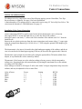
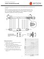
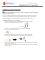
T6 Radiator Series Installation Guide Revised 1/14 T6-T
T6 - CENTRALLY CONNECTED RADIATOR
1
T6 Radiator Series
Table of Contents
MYSON
Before You Begin ..........................................................................3
Bottom Center Connections .......................................................4-5
Side Connections …...................................................................6-7
Optional Piping Arrangements ......................................................8
Wall Bracket Installation ...........................................................9-11
Diverter Valve Installation …………………………………………..12
“H” Valve Specifications …………………………………………13-14
System Start-Up & Maintenance .................................................15
Myson, Inc. Limited Warranty
Myson, Inc warrants the following products against defects in material and workmanship to the
original owner for the duration listed from date of installation or three months after date of shipment,
whichever comes first.
The remedy in all cases shall be to repair or replace the product at Myson’s discretion upon
verification of a factory defect. If replacement is required, and an exact replacement product is no
longer available, Myson reserves the right to furnish a similar product of equal value.
NO REMOVAL, SHIPPING OR INSTALLATION EXPENSES ARE REIMBURSIBLE
The original purchaser is responsible for determining the suitability of the Myson product for their
installation. Installation and troubleshooting should be performed by a competent technician with
knowledge of hydronic heating and/or basic electricity.
Damages occurring during shipment, transit, storage or handling, abuse, neglect, accident,
misapplication, improper water source or connection, fire, flood or other Acts of God are not
covered. Freight damage claims MUST be made within 10 days of receipt from Myson.
No Exceptions.
STEEL PANEL RADIATORS — SELECT, T6, DÉCOR, COLUMN AND BENCH The
duration of warranty for steel panel radiators is 5 Years.
What is covered:
•
•
Painted finishes will not peel or flake from the surface of the radiator.
The body of the radiator and its welded joints will not leak when the product is properly
installed and maintained according to Myson’s instructions.
What is not covered:
•
•
Rust occurring from improperly sealed threaded connections or oxygen corrosion.
Electrolytic corrosion caused by failure to flush the system properly after initial
installation.
2
T6 Radiator Series
Before You Begin
INSPECT FOR DAMAGE
NOTE: Inspect for concealed shipping damage. Damage claims MUST be reported within 10 days of receipt.
NO EXCEPTIONS. Call 1-800-698-9690.
INSPECT FOR COMPLETENESS
Unpack the T6 carefully to avoid damage or loss of parts.
The T6 radiator includes:
Wall Brackets (2) for 16” through 63” width radiators, (3) for 70” and 78” width radiators
(2) Adapters for ½” copper compression (standard) or ½” PEX (optional)
The following are factory installed:
(2) Solid Plugs
(1) Air Vent
(1) Valve insert (Thermostatic Control optional)
APPLICATION
Myson T6 radiators must only be used in a pumped, closed loop hydronic heating system. DO NOT
INSTALL ON A STEAM OR GRAVITY HOT WATER SYSTEM. T6 radiators are designed and
constructed for a maximum working pressure of 145 PSI and no more than 230 degrees F water temperature.
Please consult national and local codes for specific restrictions that may be imposed on your installation.
Position radiators away from the circulating pump to avoid either excess pressure that could force water out
the air vent or suction which cold draw air into the system. The preferred positioning for the T6 radiator is
below a window where it can minimize downdrafts from glazed areas.
Panel radiators may be hot to the touch. Generally, the surface temperature is 10 to 12 degrees Fahrenheit
below the system water temperature. Care must be taken to consider the room occupant’s ability to sense or
understand that radiators may be hot. Should radiator surface or system water temperature be an issue, please
contact Myson at 1-800-698-9690 for information on the Myson LST radiators. LST (Low Surface
Temperature) Radiators can be a viable solution where temperature is a safety concern.
CONNECTIONS
There are two very different connection options for the T6 radiators, and the instructions are separated in the
booklet.
Bottom Center Connections: These connections must be used for the internal thermostatic valve to work. The
inlet must be the left hand connection as you face the front of the radiator. For series connection (maximum 2
GPM), HV-A or HV-S bypass valves may be used.
Side Tappings: The T6 may be connected like a conventional panel radiator. This arrangement negates the
effectiveness of the internal thermostatic valve. It will be necessary to cap the bottom center connections with
brass caps. The TRV insert should be removed and replaced with one of the plugs furnished with the radiator.
3
T6 Radiator Series
Center Connections
PIPING CONSIDERATIONS
T6 radiators are to be connected to one of the following piping systems: Home Run, Two Pipe
Reverse Return, or Monoflo. See page 8 for basic illustrations.
A limited number of T6 radiators may be connected in series using “H” Series By-Pass Valves. The
circuit must be limited to 2 GPM Maximum. See page 12.
Installation Using Center Connections
Center connections MUST be used in order for the built-in thermostatic valve to function.
The supply MUST be on the left hand side as you face the front of the radiator.
Each pipe center is one inch (1”) either side of the centerline of the radiator and 2 5/8” from the
finished wall.
Remove the two plastic paint caps from the center connections and connect either ½” copper pipe
using the compression adapters (p/n 101-68-44) or ½” PEX using the optional PEX adapters (p/n
164-68-50).
The thermostatic valve insert is located in the right hand upper tapping of the radiator, and the air
vent is located in the left hand upper tapping. Each may be moved to the opposite side if desired.
Thermostatic room control may be achieved by using the optional Herz TS head available from
Myson, or any Danfoss RA series control (by others).
Thermostatic Valve Inserts are color coded according to factory presets, which correspond to
radiator size. Presetting helps with system balance by limiting the maximum flow to the radiator
according to BTUH output.
Insert settings are based on 158 degree F. inlet water with a 30 degree temperature drop across the
radiator, and may be adjusted for less or more flow.
Color of Insert
White
Black
Green
Blue
Red
Preset
1.1
3.9
5.2
6.5
N
Setting
1
2
3
4
5
6
7
4
BTUH
1,700
2,700
3,400
4,100
5,500
6,850
8,200
Radiator T6 Series Center Connections (cont) Swapping the right-hand side built-in valve to the left-hand side is no problem at all at
any time.
Radiators are delivered with protective caps. After removing the protective cap
(pos. A) the following thermostat heads can be fitted directly to the built-in valve
(pos. B): “RA 2000”, “RAW” by Danfoss, “VK” by Heimeier, “D” by Herz,
“thera DA” by MNG and “UNI XD” by Oventrop.
Setting Information
•
•
•
•
Bottom center connections must be used for
internal valve function.
Remove Site Cap or Probe Element.
Turn the Setting Ring counter-clockwise to the
desired presetting—the setting value (1, 2, …
7, N) must be positioned above the mark.
Presetting can be selected in grades of 0.5
between 1 and 7. Presetting is released in the
setting “N”.
5
T6 Radiator Series
Optional Side Valve Connections
Installation Using Side Connections
Note:
Center connections MUST be used in order for the internal distribution tubing and the built-in
thermostatic valve to function.
The T6 IVC Radiator is designed to be connected using the bottom connections. If necessary the
radiator may be installed using the side tappings although a better alternative is to use Myson’s
Select Series Radiators. For more information please contact Myson at 800-698-9690.
Preparing the T6 Radiator for side connections.
• Remove the two plastic caps from the bottom center connections and discard.
• Replace with nickel plated brass caps, PN: T6BCC.
T6BCC
•
•
Remove one of the blanking plugs from one of the lower side tappings.
Remove the thermostatic valve insert.
•
•
Replace with the blanking plug removed from one of the lower side tappings.
Remove the air vent assembly, separate and discard the black extension piece.
•
Replace the modified air vent in the top tapping. (Air vents should always be positioned on
the return side of the radiator.)
Make sure all tappings are clean and free of debris before proceeding with valve installation
shown on page 7.
•
6
T6 Radiator Series
Optional Side Valve Installation
MYSON
Applies to installation using side tappings.
Myson products are designed to be installed by professional trades people. Myson instructions
are meant to be thorough; however it is assumed that the installer has the appropriate
technical knowledge related to building codes, standard trade practices, and proper use of the
tools of the trade. Should a homeowner without such knowledge or skill take it upon
him/herself to attempt the installation, Myson will not be responsible for any damages, injuries
or unsatisfactory performance of the Myson product used.
NOTE: MYSON products have BSP male and female threads. BSP threads are a straight
running thread NOT tapered like NPT. Myson Radiator Valves are designed with BSP
threads at radiator side and NPT or compression connections to system piping.
Step 1 Clean all threaded surfaces (both external and internal).
Step 2 Apply teflon tape or pipe dope to the male threads, leaving the first thread exposed.
If using pipe dope, also apply to the female threads of the radiator. Common practice
to seal BSP threads is to use heavy duty teflon tape, such as is used to seal gas pipe
fittings, or anaerobic pipe dope.
Step 3 Using accepted trade practices assemble and wrench tighten fittings until
proper alignment is obtained.
Valve body stop
Copper pipe must
extend all the way to
stop. This is critical.
Threaded
Connection
7
MYSON
T6 Radiator Series
Optional Piping Arrangements
The following drawings are general
examples. They are diagrammatic only.
Consult a certified heating professional
for your specific application.
General information on the use of Monoflo tees:
•
•
•
Scoop type is placed on the supply
Venturi type on the return
If heating unit is below main or more than 4
feet horizontally from the main, use two
monoflo tees facing each other
The T6 radiator is designed to be connected using the 2”cc bottom center connections. These connections utilize the efficient use of special internal piping and the included internal Thermostatic Radiator Valve. The “Home Run System” piping with a modulating circulator is the most efficient installation method. The bottom center connections also work well with the “Monoflo (1 Pipe) System”. If connected in series (“Series Loop”) an “H” style by‐pass valve must be used and the circuit must be limited to 2 gpm. This method is not recommended. The T6 radiator may also be installed using the alternate end panel tappings, however this will render the internal piping and TRV non‐
operational and is not recommended.
8
T6 Radiator Series
Solid Wall Bracket Installation
ATTENTION: For the correct installation of radiators it is essential that the fixing of the radiator is
carried out in such a way that it is suitable for intended use AND predictable misuse. A number of
elements need to be taked into consideration including the fixing method ussed to secure the radiator
to the wall, the type and condithion of the wall itself, and any additional potential forces or weights,
prior to finalizing the installation.
Mounting Positions, Dimensions and Wall Brackets
Y
T6
Type
Nominal Height
Y
Z
(in)
(in)
(in)
12 - 24
3 3/8
2 5/8
TK2
Y = Wall to side connection.
Z = Wall to centre bottom connection.
Y
Z
315/16
1 9 / 16
4 5 / 16
315/16
23/4
1 9 / 16
Wall Bracket
1-1/16"
11/ "
16
B M8
Nominal Height
(in)
12
for all radiators from
an overall length of
707/8" and longer.
A M6
Plastic insert
M8
A (in)
Overall length
2
B M6
A M8
Y=
M6
B (in)
A (in)
B (in)
5
7/
16
-
16
9
3/
8
5/
8
20
13 5/16
5 5/8
13 7/8
6 3/16
24
17 1/4
5 5/8
17 13/16
6 3/16
5
6
9
T + 10% = OA
T = Radiator
width
OA
6
15/
16
9
3
3/
16
Right
T6 Radiator Series
Conventional Wall Installation Using Optional EZ-Brackets)
Step 1 Locate studs in wall where the radiator is to be mounted.
Step 2 Mount the brackets so the radiator is a minimum of 4 inches off the floor.
• Failure to allow 4” minimum clearance below radiator can significantly reduce
radiator performance.
• Attach brackets firmly to the studs using appropriate hardware making sure
the spring loaded connection on brackets is on top.
• All Select Radiators use 2 brackets except as noted on page 9.
• Use a level to assure bracket is plumb.
Step 3 Position radiator to line up with the supply and return pipes.
Step 4 To install the radiator on the brackets, set the bottom edge of the rear panel on the bottom
part of the bracket then gently lift and snap the top clip into the grille of the radiator.
NOTE: For mounting instructions of the T6 radiator using the new style EZ
brackets please refer to the instructions included with the brackets.
Many MYSON products are in excess of 70 pounds. Care should be taken to have help to lift
larger radiators into place to avoid lifting injuries.
10
T6 Radiator Series
“H” Diverter Valve Installation
MYSON T6 DIVERTER VALVE SYSTEM
When using “H” style diverter valves to
connect multiple radiators in series, it is
necessary to size the downstream radiators
based on the lower inlet water temperature at
each radiator caused by the mixing of return
water.
The following is an example of how to properly size each radiator.
1
2
3
4
5
6
7
8
Rooms in order of flow
Heat Loss In BTUH
Available Wall Space (ft)
Max Height (inches)
Select ∆ T for system
Maximum supply temp
Total Heat Load
Total Loop GPM*
Supply Temp Per Room
Bedroom 2
Bathroom
4,200
3,000
3
2
16
24
∆ T 30°F
180°F
Q = 21,200 BTUH
GPM = Q/(500 ∆ T ) = 21,200/500X30 = 1.41 GPM
180°F
174°F
Bedroom 3
5,400
3
16
170°F
Line 6. Sum of all heat loads in Line 2.
Line 7. Use formula to calculate GPM
NOTE: Flow rate cannot exceed 2 GPM on a diverter valve system.
Using a larger ∆T lowers the GPM requirement.
Line 8. Calculate the supply temperature of each room according to the following examples.
Supply Water Temperature
Supply Water Temperature
Supply Water Temperature
Supply Water Temperature
Bedroom 2 = 180⁰F.
Bathroom = 180⁰F minus 4200 / (500 x 1.41) = 174⁰ F.
Bedroom 3 = 174⁰F minus 3000 / (500 x 1.41) = 170⁰ F.
Master BR = 170⁰F minus 5400 / (500 x 1.41) = 162⁰ F.
11
Master
Bedroom
8,600
7
24
162°F
T-6 Radiator Series
H -Valve Dimensions
HV-S Twin Entry By-Pass valve - Straight
2"
22mm BSP
2 3/8"
Turn stop flow to radiator
turn on both sides.
CLOSE
OPEN
standard: adapters to 1/2"
copper tube
optional: adapters to 1/2"
pex
3 3/8"
HV-A Twin Entry By-Pass valve - Angle
2"
1 38"
By-pass adjustment
Drain
12
13
T6 Radiator Series
System Start-Up & Maintenance
Failure to flush system of debris and flux may cause premature radiator failure,
which can result in leaks and property damage NOT covered under the Myson
Warranty.
SYSTEM START-UP
Step 1 Fill and vent the system.
Step 2 Run the system for two (2) hours at full temperature with all radiator valves in the
open position.
Step 3 Shut off and drain the system while the water is still hot.
Step 4 Refill the system.
Step 5 Reheat, vent, and balance the system.
Step 6 Once the Radiator is filled with water the system should be left filled.
Step 7 System should be checked for leaks on seasonal start-ups. Leaks must be
repaired as automatic system fill valves allow fresh water/oxygen into
the system attacking radiators internally.
MAINTENANCE & CLEANING
1 Once operating, avoid the introduction of fresh water and oxygen to the system to
prevent corrosion.
2 An occasional wiping with a damp cloth using a non abrasive detergent can protect
the finish of your Myson Panel Radiator.
3 The use of abrasive cleaners will damage the surface of your radiator, and void the
manufacturer’s warranty.
ADDITIVES
Treatment of the primary water is not usually required in a properly designed system.
Treatment may be necessary if either:
1 Local waters are known for their content of corrosive material or if high bacterial levels
are present.
2 If there is a possibility that the system may be idle during a prolonged period of freezing
temperatures, system should be either drained or protected with antifreeze. If either
corrosion inhibitors or anti-freeze is to be used, it should be added AFTER the system has
been flushed in the final stages. Use only anti-freeze suitable for potable water.
Do not put heating system into operation without checking for leaks with the system up to
full operating temperature. Leaks can appear in a heated system that were not noticeable
with a cold system or air pressure check.
14
T6 Radiator Series
Notes
MYSON
15
Myson T6 Radiator Installation Manual 6/2012 MYSON INC. 948 Hercules Drive, Suite 5, Colchester, VT 05446 T 800.698.9690 F 802.654.7022 www.mysoninc.com 16