1
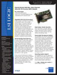
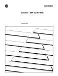
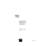
Quick Hardware Setup Guide
LSI Logic MegaRAID®
SCSI 320-2E Controller
MegaRAID 320-2E Controller Installation
Caution: Make a backup of your data before you change your
system configuration. Otherwise you may lose data.
Follow these steps to install the MegaRAID SCSI 320-2E. Each
step is explained more fully in the following table:
Step Action
1
Unpack the MegaRAID SCSI 320-2E.
2
Turn off the computer, remove the power cord, and remove the cover.
3
Verify the MegaRAID SCSI 320-2E jumper settings.
4
Install the MegaRAID SCSI 320-2E.
5
Connect the SCSI devices to the MegaRAID SCSI 320-2E.
6
Set the target IDs for the SCSI devices.
7
Set SCSI termination.
8
Replace the computer cover and turn the power on.
9
Run the MegaRAID BIOS Configuration Utility.
10
Install the operating system driver.
Step 1: Unpack the MegaRAID SCSI 320-2E
Thank you for purchasing the MegaRAID SCSI 320-2E Controller.
Please take a few minutes to read this quick hardware setup guide
before you install the MegaRAID SCSI 320-2E. If you need more
information about any topic covered in this guide, refer to the other
documents on your MegaRAID Universal Software Suite CD.
If the MegaRAID SCSI 320-2E Controller appears to be damaged,
or if the MegaRAID Universal Software Suite CD is missing, contact
LSI Logic or your MegaRAID OEM support representative.
Contents of MegaRAID Universal Software Suite CD
The MegaRAID Universal Software Suite CD is packaged with the
MegaRAID SCSI 320-2E. The CD contains utility programs, device
drivers for various operating systems, and the following
documentation:
Unpack and install the MegaRAID SCSI 320-2E Controller in a
static-free environment. Remove the MegaRAID SCSI 320-2E from
the antistatic bag and inspect it for damage.
Step 2: Prepare the Computer
Turn off the computer and remove the power cord from the back of
the power supply. Remove the cover from the chassis. Make sure
the computer is disconnected from the power and from any
networks before installing the controller card.
Step 3: Review the MegaRAID Controller Jumpers
Make sure the jumper settings on the MegaRAID SCSI 320-2E are
correct. The jumpers are set at the factory, and you probably do not
need to change them. The following table lists the jumpers and
connectors on the RAID controller.
• MegaRAID 320 Storage Adapters User’s Guide
Item
• MegaRAID Configuration Software User’s Guide
J1
Description
Type
Write Pending Indicator
(Dirty Cache LED)
2-pin header.
Connector for enclosure LED to indicate when
data in the cache has yet to be written to the
device. Optional.
• MegaRAID Device Driver Installation User’s Guide
• Software license agreement and warranty registration card
J2
Onboard BIOS Enable
Technical Support
If you need help installing, configuring, or running the MegaRAID
SCSI 320-2E Controller, contact LSI Logic Technical Support:
Phone Support: 678-728-1250 or 800-633-4545 #3
Web Site:
http://www.lsilogic.com/downloads/selectDownload.do
E-mail: [email protected]
No jumper = Enabled (default setting)
Jumpered = Disabled
J4
I2C Header
2-pin header. Reserved.
J5
SCSI Termination Enable
Channel 0
2-pin header.
J6
SCSI Termination Enable
Channel 1
®
Jumper pins 1–2 to enable software control of
SCSI termination through drive detection.
Jumper pins 2–3 to disable onboard SCSI
termination.
In Europe, you can contact the LSI Logic Technical Support team:
Phone Support: +44.1344.413.441 (English) or
+49.89.45833.338 (Deutsch)
E-mail: [email protected]
2-pin header.
No jumper installed enables onboard SCSI
termination. (Refer to J17 and J18.) This is
the default.
J7
Serial Port (RS232)
3-pin connector.
Connector is for diagnostic purposes.
Pin 1 – RXD (Receive Data)
Pin 2 – TXD (Transmit Data)
Pin 3 – GND (Ground)
DB11-000055-00
Version 1.0
August 2004
Copyright © 2004 by LSI Logic Corporation. All rights reserved.
Quick Hardware Setup Guide
Item
J9
Description
Type
Internal SCSI Channel 0
connector
68-pin connector.
Bracket Screw
Press Here
Internal high-density SCSI connector.
Connection is optional.
J10
Internal SCSI Channel 1
connector
68-pin connector.
Internal high-density SCSI connector.
Connection is optional.
J11
Mode Select
2-pin header. Reserved for internal use.
J12
External SCSI Channel 0
connector
68-pin connector.
Press Here
External very-high density SCSI connector.
Connection is optional.
J14
External SCSI Channel 1
connector
68-pin connector.
External very-high density SCSI connector.
Connection is optional.
J15
Termination Power
–
J16
Termination Power
–
The following diagram shows the location of the jumpers and
connectors on the MegaRAID SCSI 320-2E Controller.
J5 J6
Internal High-Density
68-Pin SCSI Connector
Internal High-Density
68-Pin SCSI Connector
J9 Ch 0 Int
J10 Ch1 Int
32-Bit Slot (3.3 V)
J1 J2 J3
PCI-Express Slot
J4
J7
J12 Channel 0
External
Very-High
Density
68-Pin SCSI
Connector
J11
Edge of
Motherboard
64-Bit Slots (5 V)
J14 Channel 1
External
Very-High
Density
68-Pin SCSI
Connector
Step 5: Connect SCSI Devices to the MegaRAID Controller
J15
J16
Step 4: Install the MegaRAID SCSI 320-2E Controller
Install the MegaRAID SCSI 320-2E Controller in a PCI-Express slot,
as shown in the following figure. Press down gently, but firmly, to make
sure that the card is properly seated in the slot. The bottom edge of
the controller card must be flush with the slot. Attach the MegaRAID
SCSI 320-2E to the computer chassis with the bracket screw.
Caution: If your board has a memory module, never apply
pressure to the module when inserting the adapter.
Applying pressure could break the module.
Connect SCSI devices to the internal, high-density, 68-pin SCSI
connectors (J9 and J10) and/or the external, very-high density,
68-pin SCSI connectors (J12 and J14). To achieve maximum data
throughput, use only Ultra320 SCSI devices. The MegaRAID SCSI
320-2E Controller supports up to 30 Ultra320 SCSI devices at a
maximum SCSI bus cable length of 12 meters. You also can
connect Ultra160 and Ultra2 SCSI devices. The MegaRAID 320
Storage Adapters User’s Guide lists the maximum number of
devices and maximum cable length for each SCSI device.
Disable SCSI termination on all devices that are not connected at
the end of the SCSI bus. Use only high-quality ribbon SCSI cables
for internal devices and high-quality round SCSI cables for
external devices.
Step 6: Set the Target IDs for the SCSI Devices
Each connected SCSI device must have a unique Target ID (TID),
ranging from 0 to 15 for 16-bit devices. Note that under the DOS
Advanced SCSI Programming Interface, SCSI devices are limited
to SCSI IDs 0–6. The MegaRAID SCSI 320-2E Controller is
automatically assigned TID 7, which has the highest priority. Verify
that no two SCSI devices are set to the same TID. Change the TIDs
as needed. Refer to the SCSI device documentation if you are not
sure how to do this.
Step 7: Set SCSI Termination
The SCSI bus, which consists of connected SCSI cables and SCSI
devices, is an electrical transmission line that must be terminated
properly to minimize signal reflections and prevent data loss. Disk
enclosures normally handle termination for the SCSI devices in the
enclosure. Refer to your enclosure documentation for details.
Page 2
Quick Hardware Setup Guide
SCSI termination must be set at each end of the SCSI bus, as
shown in the following figure. In this example, only internal SCSI
devices are connected to the MegaRAID SCSI 320-2E Controller.
The MegaRAID SCSI 320-2E Controller automatically terminates its
end of the SCSI bus only if internal and external devices are
connected to the SCSI bus. It automatically disables termination if
both internal and external devices are connected to the bus,
because the MegaRAID SCSI 320-2E Controller is then in the
middle of the bus.
SCSI
Terminator
Press <Ctrl><M> to run MegaRAID SCSI 320-2E BIOS Configuration
Utility
Step 9: Run the MegaRAID BIOS Configuration Utility
When the “Press <Ctrl><M>” message appears on the screen,
press <Ctrl><M> immediately to run the MegaRAID BIOS
Configuration Utility. Refer to the MegaRAID Configuration Software
User’s Guide on the MegaRAID Universal Software Suite CD for
details on how to run and use this program.
Step 10: Install the Operating System Driver
The MegaRAID SCSI 320-2E can operate under MS-DOS or any
DOS-compatible operating system using the standard AT BIOS INT
13h Hard Disk Drive interface. To operate with other operating
systems, you must install software drivers.
Termination on Controller
Enabled
SCSI Devices
(Termination Disabled on Both)
For a disk array, set SCSI bus termination so that removing or
adding a SCSI device does not disturb termination. To do this,
connect the MegaRAID SCSI 320-2E Controller to one end of the
SCSI cable and connect a SCSI terminator module at the other end
of the cable. Attach SCSI devices to the connectors between the
two ends, and disable termination on them. The following figure
shows an external drive enclosure with seven SCSI drives.
Termination is enabled at the end of the cable closest to the “last”
SCSI drive, which is assigned SCSI ID6.
External
SCSI Drives
The MegaRAID Universal Software Suite CD includes drivers for
the supported operating systems. You can view the supported
operating systems and download the latest drivers for RAID
adapters on the LSI Logic web site at
http://www.lsilogic.com/downloads/selectDownload.do.
Access the download center and follow the steps to download
the driver.
Refer to the MegaRAID Device Driver Installation User’s Guide on
the MegaRAID Universal Software Suite CD for details on installing
the driver. Be sure to use the latest Service Packs provided by the
operating system manufacturer and review the readme file that
accompanies the driver.
Supported RAID Levels
The MegaRAID SCSI 320-2E Controller supports disk arrays using
the following RAID levels:
ID 0
ID 1
• RAID 0 (Data striping): Data is striped across all disks in the
ID 2
ID 3
•
ID 4
ID 5
ID 6
Termination
Enabled
MegaRAID SCSI 320-2E
SCSI ID 7
•
Step 8: Power-Up the Computer
Replace the computer cover and connect the power cords to all
SCSI devices and to the computer. Turn on the power to all devices.
Be sure the SCSI devices are powered up before the computer or
at the same time as the computer. Otherwise, the computer may
not recognize the SCSI devices.
Observe the messages that appear during the boot process, until
you see the message:
•
•
array, enabling very fast data throughput. There is no data
redundancy. All data is lost if any disk fails. (1–30 disk drives)
RAID 1 (Disk mirroring): Data is written simultaneously to two
disks, providing complete data redundancy if one disk fails. The
array capacity is one-half of total disk space. (2 disk drives)
RAID 5 (Disk striping with distributed parity): Data is striped
across all disks in the array. Part of the capacity of each disk
stores parity information that reconstructs data if a disk fails.
Provides good data throughput for applications with high read
request rates. (3–30 disk drives)
RAID 10 (RAID 1 and RAID 0 in spanned arrays): Uses
mirrored pairs of disks to provide complete data redundancy.
Provides high data throughput rates. (4–28 disk drives)
RAID 50 (RAID 5 and RAID 0 in spanned arrays): Uses both
parity and disk striping across multiple disks to provide
complete data redundancy. Provides high data throughput rates.
(6–30 disk drives)
DB11-000055-00, Version 1.0, August 2004
Copyright © 2004 by LSI Logic Corporation. All rights reserved.
LSI Logic, the LSI Logic logo design, and MegaRAID are registered trademarks of
LSI Logic Corporation. All other brand and product names may be trademarks of their
respective companies.
LSI Logic Corporation reserves the right to make changes to any products and services
herein at any time without notice. LSI Logic does not assume any responsibility or
liability arising out of the application or use of any product or service described herein,
except as expressly agreed to in writing by LSI Logic; nor does the purchase, lease, or
use of a product or service from LSI Logic convey a license under any patent rights,
copyrights, trademark rights, or any other of the intellectual property rights of LSI Logic
or of third parties.
LSI Logic products are not intended for use in life-support appliances, devices, or
systems. Use of any LSI Logic product in such applications without written consent of
the appropriate LSI Logic officer is prohibited.
Purchase of I2C components of LSI Logic Corporation, or one of its sublicensed
Associated Companies, conveys a license under the Philips I2C Patent Rights to use
these components in an I2C system, provided that the system conforms to the I2C
standard Specification as defined by Philips.
You can find a list of the LSI Logic Corporation U.S. distributors, international
distributors, sales offices, and design resource centers on the LSI Logic web site at:
http://www.lsilogic.com/contacts/index.html