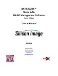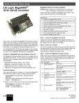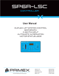
1
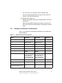
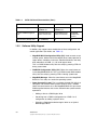
USER’S GUIDE
MegaRAID® SATA 150
Storage Adapters
July 2006
Version 1.5
®
P/N: 80-00152-01 Rev. A
Electromagnetic Compatibility Notices
This device complies with Part 15 of the FCC Rules. Operation is subject to the following two conditions:
1. This device may not cause harmful interference, and
2. This device must accept any interference received, including interference that may cause undesired operation.
This equipment has been tested and found to comply with the limits for a Class B digital device, pursuant to part 15
of the FCC Rules. These limits are designed to provide reasonable protection against harmful interference in a
residential installation. This equipment generates, uses, and can radiate radio frequency energy and, if not installed
and used in accordance with the instructions, may cause harmful interference to radio communications. However,
there is no guarantee that interference will not occur in a particular installation. If this equipment does cause harmful
interference to radio or television reception, which can be determined by turning the equipment off and on, the user
is encouraged to try to correct the interference by one or more of the following measures:
•
•
•
•
Reorient or relocate the receiving antenna.
Increase the separation between the equipment and the receiver.
Connect the equipment into an outlet on a circuit different from that to which the receiver is connected.
Consult the dealer or an experienced radio/TV technician for help.
LSI Logic is not responsible for any radio or television interference caused by unauthorized modification of this
equipment or the substitution or attachment of connecting cables and equipment other than those specified by LSI
Logic. The correction of interferences caused by such unauthorized modification, substitution, or attachment will be
the responsibility of the user.
The LSI Logic MegaRAID SATA storage adapters are tested to comply with FCC standards for home or office use.
This Class B digital apparatus meets all requirements of the Canadian Interference-Causing Equipment Regulations.
Cet appareil numérique de la classe B respecte toutes les exigences du Règlement sur le matériel brouilleur du
Canada.
This is a Class B product based on the standard of the Voluntary Control Council for Interference from Information
Technology Equipment (VCCI). If this is used near a radio or television receiver in a domestic environment, it may
cause radio interference. Install and use the equipment according to the instruction manual.
LSI Logic Corporation
North American Headquarters
Milpitas, CA
408.433.8000
ii
Copyright © 2002–2006 by LSI Logic Corporation. All rights reserved.
This document contains proprietary information of LSI Logic Corporation. The
information contained herein is not to be used by or disclosed to third parties
without the express written permission of an officer of LSI Logic Corporation.
LSI Logic products are not intended for use in life-support appliances, devices,
or systems. Use of any LSI Logic product in such applications without written
consent of the appropriate LSI Logic officer is prohibited.
Purchase of I2C components of LSI Logic Corporation, or one of its sublicensed
Associated Companies, conveys a license under the Philips I2C Patent Rights to
use these components in an I2C system, provided that the system conforms to
the I2C standard Specification as defined by Philips.
Document P/N: 80-00152-01, Version 1.5 (July 2006) This document describes
LSI Logic Corporation’s SATA 150 PCI to Serial ATA Storage Adapters and will
remain the official reference source for all revisions/releases of these products
until rescinded by an update. This manual applies to the MegaRAID SATA 1502, SATA 150-4, and SATA 150-6 storage adapters.
LSI Logic Corporation reserves the right to make changes to any products herein
at any time without notice. LSI Logic does not assume any responsibility or
liability arising out of the application or use of any product described herein,
except as expressly agreed to in writing by LSI Logic; nor does the purchase or
use of a product from LSI Logic convey a license under any patent rights,
copyrights, trademark rights, or any other of the intellectual property rights of
LSI Logic or third parties.
Copyright © 2002–2006 by LSI Logic Corporation. All rights reserved.
TRADEMARK ACKNOWLEDGMENT
LSI Logic, the LSI Logic logo design, MegaRAID, and Power Console Plus are
registered trademarks of LSI Logic Corporation. Windows and Windows NT are
registered trademarks of Microsoft Corporation. All other brand and product
names may be trademarks of their respective companies.
CD
To receive product literature, visit us at http://www.lsilogic.com
For a current list of our distributors, sales offices, and design resource
centers, view our web page located at
http://www.lsilogic.com/contacts/index.html
iii
Copyright © 2002–2006 by LSI Logic Corporation. All rights reserved.
iv
Copyright © 2002–2006 by LSI Logic Corporation. All rights reserved.
Preface
This book is the user’s guide for the MegaRAID® SATA 150 storage
adapters. It contains complete physical installation instructions, as well
as physical and electrical specifications, for the SATA 150 storage
adapters.
Audience
This document assumes that you have some familiarity with RAID
controllers and related support devices. The people who benefit from this
book are:
•
Anyone installing an SATA 150 storage adapter in a host system
•
Engineers who are designing an SATA 150 storage adapter into a
host system
•
Engineers and managers who are evaluating the SATA 150 storage
adapter for possible use in a system
Organization
Use this manual to install and configure your MegaRAID SATA 150
storage adapter in the host system.
This document has the following chapters and appendixes:
•
Chapter 1, Introduction, introduces the SATA 150 storage adapters
and describes their main supported features.
•
Chapter 2, Hardware Installation, describes how to install an SATA
150 storage adapter in a host system.
•
Chapter 3, SATA 150 Storage Adapter Characteristics, provides
the environmental and electrical specifications for the SATA 150
MegaRAID SATA 150 Storage Adapters User’s Guide
Copyright © 2002–2006 by LSI Logic Corporation. All rights reserved.
v
storage adapters. This chapter also provides the mechanical
drawing, jumper definitions, and connector locations for the SATA
150 storage adapters.
•
Appendix A, Glossary of Terms, defines terms and abbreviations
that are used in this manual.
•
Appendix B, MegaRAID Problem Report Form, provides forms to
send or fax to LSI Logic if you encounter difficulty with your SATA
150 storage adapter.
MegaRAID System Installation Sequences and Document Organization
The following table outlines the installation, configuration, and
management tasks for a MegaRAID Serial ATA system. Each sequence
consists of a series of steps and operations that the reference manual
explains. LSI Logic recommends performing the tasks in this sequence
when you install and configure the SATA 150 adapter.
Sequence Task
vi
Reference Manual
1
Understand RAID system theory and operation.
MegaRAID Configuration Software User’s
Guide
2
Install the MegaRAID Serial ATA storage adapter and the
related hardware.
MegaRAID SATA 150
Storage Adapters User’s
Guide
3
Configure the physical arrays and logical devices using either
the MegaRAID Configuration Utility (CU) or the WebBIOS
CU.
MegaRAID Configuration Software User’s
Guide
4
Install the MegaRAID device drivers.
MegaRAID Device Driver
Installation User’s Guide
5
Manage, monitor, and reconfigure the RAID array using either MegaRAID Configurathe MegaRAID Manager tool or the Power Console Plus™
tion Software User’s
tool. Each tool runs under an operating system and can man- Guide
age the RAID array while the system is operating.
Preface
Copyright © 2002–2006 by LSI Logic Corporation. All rights reserved.
Related Publications
MegaRAID Device Driver Installation User’s Guide
Document Number: DB11-000018-02
This document explains how to install the MegaRAID device driver for
your operating system. The information in this document is independent
of the back-end bus and applies to both MegaRAID SCSI storage
adapters and Serial ATA storage adapters.
MegaRAID Configuration Software User’s Guide
Document Number: DB15-000269-01
This document explains how to use the RAID system configuration,
monitoring, and management tools that MegaRAID provides. These tools
include the BIOS-based MegaRAID Configuration Utility and WebBIOS
Configuration Utility, as well as the MegaRAID Manager OS-based tool
and the Power Console Plus OS-based tool. The information in this
document is independent of the back-end bus and applies to both
MegaRAID SCSI storage adapters and Serial ATA storage adapters.
Revision History
Revision
Date
Remarks
1.5
July 2006
Corrected text about the J4 Write Pending connector for the SATA
150-6 and SATA 150-4 controllers. Updated jumper information to
state not to use a jumper on the J1 connector for SATA 150-6 and
SATA 150-4. In addition, updated contact information for Technical
Support.
1.4
September 2004
Added information about drive roaming, drive migration, and
alarm beep codes. Did general editing on the document.
1.3
November 2003
Added a note about operating system support, logical drive deletion, and headings for RAID Configuration Utilities and Technical
Support in Chapter 1. Corrected version number for the Serial
ATA specification (1.0).
1.2
September 2003
Added enclosure management information and updated the list of
supported operating systems.
Preface
Copyright © 2002–2006 by LSI Logic Corporation. All rights reserved.
vii
Revision
Date
Remarks
1.1
April 2003
Added the MegaRAID SATA 150-4 RAID Storage Adapter (RSA).
1.0
December 2002
Initial release of this document.
viii
Preface
Copyright © 2002–2006 by LSI Logic Corporation. All rights reserved.
Contents
Chapter 1
Introduction
1.1
1.2
Chapter 2
Hardware Installation
2.1
2.2
2.3
2.4
2.5
Overview of Main Adapter Features
1.1.1
Enclosure Management
1.1.2
Patrol Read
1.1.3
SMART Technology
1.1.4
Alarm Beep Codes
1.1.5
Drive Roaming and Drive Migration
1.1.6
Logical Drive Deletion
1.1.7
Background Initialization
1.1.8
Operating System Support
1.1.9
Technical Support
SATA 150 Storage Adapter Characteristics
1.2.1
Hardware and Software Characteristics
1.2.2
Software Utility Support
1-1
1-2
1-2
1-2
1-3
1-4
1-4
1-5
1-5
1-6
1-6
1-7
1-8
Installation Overview
Hardware Requirements
Quick Installation Instructions
Detailed Installation Instructions
After Installing the Storage Adapter
2-1
2-2
2-2
2-3
2-5
Chapter 3
SATA 150 Storage Adapter Characteristics
3.1
MegaRAID PCI to Serial ATA Storage Adapters
3.1.1
MegaRAID SATA 150-6
MegaRAID SATA 150 Storage Adapters User’s Guide
Copyright © 2002–2006 by LSI Logic Corporation. All rights reserved.
3-1
3-2
ix
3.2
3.1.2
3.1.3
Physical
3.2.1
3.2.2
3.2.3
MegaRAID SATA 150-4
MegaRAID SATA 150-2
and Environmental Specifications
Electrical Characteristics
Thermal and Atmospheric Characteristics
Safety Characteristics
Appendix A
Glossary of Terms
Appendix B
MegaRAID Problem Report Form
Customer Feedback
x
Contents
Copyright © 2002–2006 by LSI Logic Corporation. All rights reserved.
3-4
3-6
3-8
3-8
3-8
3-9
Figures
2.1
3.1
3.2
3.3
Inserting the SATA
SATA 150-6 Board
SATA 150-4 Board
SATA 150-2 Board
150 Storage Adapter in a PCI Slot
Layout
Layout
Layout
Contents
Copyright © 2002–2006 by LSI Logic Corporation. All rights reserved.
2-4
3-3
3-5
3-7
xi
xii
Contents
Copyright © 2002–2006 by LSI Logic Corporation. All rights reserved.
Tables
1.1
1.2
3.1
3.2
3.3
3.4
3.5
B.1
B.2
B.3
Alarm Beep Codes
SATA 150 Board Characteristics
MegaRAID SATA 150 Characteristics
SATA 150-6 Connector and Jumper Description
SATA 150-4 Connector and Jumper Description
SATA 150-2 Connector Definitions
Maximum Power Requirements
Customer Information
System and Problem Information
MegaRAID Array and Logical Device Configuration
Contents
Copyright © 2002–2006 by LSI Logic Corporation. All rights reserved.
1-3
1-7
3-1
3-3
3-5
3-7
3-8
B-1
B-2
B-3
xiii
xiv
Contents
Copyright © 2002–2006 by LSI Logic Corporation. All rights reserved.
Chapter 1
Introduction
This chapter introduces the MegaRAID SATA 150 PCI to Serial ATA
storage adapters and consists of the following sections:
1.1
•
Section 1.1, “Overview of Main Adapter Features”
•
Section 1.2, “SATA 150 Storage Adapter Characteristics”
Overview of Main Adapter Features
The MegaRAID SATA 150 storage adapters provide a high-performance
Intelligent PCI to High Speed Serialized AT Attachment (PCI-to-Serial
ATA) interface with RAID control capabilities. These storage adapters
provide reliability, high performance, and fault-tolerant disk subsystem
management.
You can install a SATA 150 adapter on a PCI bus and use it to connect
Serial ATA drives to the host computer over a Serial ATA bus. SATA 150
storage adapters are an ideal RAID solution for the internal storage
requirements of workgroup, departmental, and enterprise systems. SATA
150 storage adapters offer a cost-effective way to implement RAID in a
server.
MegaRAID SATA storage adapters support six, four or two Serial ATA
ports. A single Serial ATA device can be connected to each port.
Note:
The MegaRAID SATA 150-2 is no longer available.
The following are descriptions of the SATA 150 adapters:
•
The MegaRAID SATA 150-6 intelligent RAID controller and storage
adapter uses three Silicon Image SiI3112A chips to support six Serial
ATA ports. The Intel 80302 processor provides the intelligent RAID
MegaRAID SATA 150 Storage Adapters User’s Guide
Copyright © 2002–2006 by LSI Logic Corporation. All rights reserved.
1-1
management capabilities. The SATA 150-6 supports RAID 0, 1, 5,
10, and 50.
1.1.1
•
The MegaRAID SATA 150-4 intelligent RAID controller and storage
adapter uses two Silicon Image SiI3112A chips to support four Serial
ATA ports. The Intel 80302 processor provides the intelligent RAID
management capabilities. The SATA 150-4 supports RAID 0, 1, 5,
and 10.
•
The MegaRAID SATA 150-2 RAID controller and storage adapter
uses a Silicon Image SiI3112A chip to support two Serial ATA ports.
The SATA 150-2 supports RAID 0 and 1.
Enclosure Management
The SATA 150-4 and SATA 150-6 controllers support enclosure
management through the same protocols used for SCSI Accessed FaultTolerant Enclosures (SAF-TE), using an I2C interface to communicate
with the storage enclosure processor. This feature allows you to use
RAID capabilities provided by the SATA 150 adapters in an enclosure
containing your hard drives.
1.1.2
Patrol Read
The Patrol Read operation reviews your system for possible physical disk
errors that could lead to physical disk failure, and then carries out actions
to correct the errors. The goal is to protect data integrity by detecting
physical disk failure before the failure can damage data. The corrective
actions depend on the disk array configuration and type of errors.
Note:
1.1.3
Patrol Read is a background operation and is designed to
minimize the impact on I/O performance.
SMART Technology
The self-monitoring analysis and reporting technology (SMART) feature
monitors the internal performance of all motors, heads, and physical disk
electronics to detect predictable physical disk failures. This feature helps
monitor physical disk performance and reliability, and protects the data
on the physical disk. When problems are detected on a physical disk,
you can replace or repair the physical disk without losing any data.
1-2
Introduction
Copyright © 2002–2006 by LSI Logic Corporation. All rights reserved.
SMART-compliant physical disks have attributes for which data (values)
can be monitored to identify changes in values and determine whether
the values are within threshold limits. Many mechanical failures and
some electrical failures display some degradation in performance before
failure
There are numerous factors that relate to predictable physical disk
failures, such as a bearing failure, a broken read/write head, and
changes in spin-up rate. In addition, there are factors related to
read/write surface failure, such as seek error rate and excessive bad
sectors.
Note:
1.1.4
See http://www.t13.org for Serial Attached ATA (SATA)
interface specifications.
Alarm Beep Codes
The SATA 150-4 and SATA 150-6 adapters have a speaker that
generates audible warnings when system errors or events occur. Beeps
occur at one-second intervals. The audible warnings do not require any
management software in order to work. Table 1.1 describes the alarm
beep codes.
Table 1.1
Alarm Beep Codes
Event or Error
Alarm Beep Code
A drive is offline
(three beeps, one second off)
A drive is running in degraded mode
(one beep, one second off)
An automatic rebuild has been completed
(one beep, three seconds off)
The temperature is above or below the
acceptable range
(two beeps, two seconds off)
The firmware receives a command from an
application to test the speaker
(four beeps)
Overview of Main Adapter Features
Copyright © 2002–2006 by LSI Logic Corporation. All rights reserved.
1-3
1.1.5
Drive Roaming and Drive Migration
Note:
Drive roaming and drive migration cannot be supported at
the same time. One or the other feature can be supported
at any one time, but not both features at the same time.
Drive roaming (also known as configuration on disk) occurs when the
hard drives are moved to different channels on the same controller and
the controller detects the RAID configuration from the configuration
information on the drives.
Configuration data is saved in both non-volatile random access memory
(NVRAM) on the RAID controller and on the hard drives attached to the
controller. This maintains the integrity of the data on each drive, even if
the drives have changed their target ID. Drive roaming is supported
across channels on the same controller, except when cluster mode is
enabled.
Drive roaming does not work if you move the drives to a new controller
and connect them to different channels. If you move drives to a new
controller, they must be on the same channel/target as they were on the
previous controller, in order to keep the same configuration.
You must power off the host system and the drive enclosure before you
use drive roaming.
Drive migration is the transfer of a set of hard drives in an existing
configuration from one controller to another. The drives must remain on
the same channel and must be reinstalled in the same order as in the
original configuration.
1.1.6
Logical Drive Deletion
The SATA 150 controllers allow you to delete unwanted logical drives and
then use the disk space for a new logical drive. You can use the
configuration utilities to create the next logical drive from the noncontiguous free space (‘holes’) and from the newly created arrays.
You can still create sequential logical drives, without using the noncontiguous segments. The utilities provide information about sequential
segments, non-contiguous segments, and physical drives that have not
been configured. You can use this information when you create logical
drives.
1-4
Introduction
Copyright © 2002–2006 by LSI Logic Corporation. All rights reserved.
Please note the following:
•
You cannot delete a logical drive during a reconstruction. Also, you
cannot delete a logical drive during a rebuild, initialization, or check
consistency of a logical drive, if that drive has a higher logical drive
number than the drive you want to delete. You must wait until these
processes have completed before deleting the logical drive.
•
Drive size extension is not possible, even though you can use noncontiguous free space to create a new logical drive.
•
You cannot move an existing logical drive to another area to protect
it from defragmentation caused by random deletion.
The MegaRAID Configuration Software User’s Guide has detailed
procedures for deleting logical drives.
1.1.7
Background Initialization
Background initialization is a process to correct parity on the virtual disks.
It ensures that striped data segments are the same on all physical disks
in a disk array.
The background initialization rate is controlled by the background
initialization rate set using your array management software. You must
stop an ongoing background initialization before you change the rate, or
the rate change will not take effect. After you stop background
initialization and change the rate, the rate change will take effect when
you restart background initialization.
Note:
1.1.8
Unlike initialization of virtual disks, background initialization
does not clear data from the physical disks.
Operating System Support
The MegaRAID Serial ATA storage adapters support several major
operating systems. LSI Logic provides device drivers and RAID
management tools for operating systems on the Universal Driver Suite
CD that accompanies the SATA boards.
You can download the latest drivers and software from the download
center on the LSI Logic web site at
http://www.lsilogic.com/cm/DownloadSearch.do. Follow the steps to
download the driver.
Overview of Main Adapter Features
Copyright © 2002–2006 by LSI Logic Corporation. All rights reserved.
1-5
Refer to the MegaRAID Device Driver Installation User’s Guide on the
Universal Driver Suite CD for information about installing the device
drivers. Be sure to use the latest Service Packs provided by the
operating system manufacturer and review the readme file that
accompanies the driver.
Note:
1.1.9
The SATA 150 adapters do not support the Windows® NT
operating system. See the LSI Logic web site for the latest
operating systems and drivers.
Technical Support
For assistance installing, configuring, or running your MegaRAID SATA
150 RAID storage adapter, contact LSI Logic Technical Support.
E-mail:
[email protected]
[email protected] (Europe)
Phone Support:
1-800-633-4545 (North America)
+44.1344.413.441 (Europe)
Web Site:
http://www.lsilogic.com/support/index.html
1.2
SATA 150 Storage Adapter Characteristics
This section describes the hardware and software characteristics of the
SATA 150 storage adapters, and the software utilities you can use for
RAID management. All models of the SATA 150 storage adapter support
these aspects of the Serial ATA and PCI specifications:
•
1-6
Serial ATA, Revision 1.0, specification:
–
150 Mbytes/s bus speed
–
Theoretical 1.5 Gbits/s data transfer rate
Introduction
Copyright © 2002–2006 by LSI Logic Corporation. All rights reserved.
•
1.2.1
–
Use a low-cost 7-pin connector with thin, flexible cables
–
Use low voltage signaling levels to reduce current draw, EM
emission, and signal switching time
PCI Specification, Version 2.2:
–
Backward compatible with previous implementations of the PCI
specification
–
SATA 150-6 and SATA 150-4 boards conform to half-size PCI
form factor. SATA 150-2 board conforms to low-profile PCI form
factor.
Hardware and Software Characteristics
Table 1.2 lists hardware and software characteristics of the SATA 150
storage adapters.
Table 1.2
SATA 150 Board Characteristics
Feature
SATA 150-6
SATA 150-4
SATA 150-2
Number of Serial ATA Ports
6
4
2
Intelligent RAID Management
Yes, using the Intel
80302 processor
Yes, using the Intel
80302 processor
No
PCI Bus Width and Speed
64-bit, 66 MHz
64-bit, 66 MHz
32-bit, 66 MHz
PCI Data Transfer Rate1
533 Mbytes/s
533 Mbytes/s
266.5 Mbytes/s
Supported RAID Levels
0, 1, 5, 10, and 50
0, 1, 5, and 10
0 and 1
SDRAM Support
64 Mbytes ECC
SDRAM
64 Mbytes ECC
SDRAM
None
Cache Function
Write-back, Writethrough, Adaptive Read
Ahead, Non-Read
Ahead, Read Ahead,
Cache I/O, Direct I/O
Write-back, Writethrough, Adaptive Read
Ahead, Non-Read
Ahead, Read Ahead,
Cache I/O, Direct I/O
None
Hot Spare Pool
Yes
Yes
No
Hardware Exclusive-OR
Generation and Checking
Yes
Yes
No
Enclosure Management Support
Using the I2C Interface
Yes
Yes
No
SATA 150 Storage Adapter Characteristics
Copyright © 2002–2006 by LSI Logic Corporation. All rights reserved.
1-7
Table 1.2
SATA 150 Board Characteristics (Cont.)
Feature
SATA 150-6
SATA 150-4
SATA 150-2
BIOS RAID Management Tools
MegaRAID CU,
WebBIOS CU
MegaRAID CU,
WebBIOS CU
MegaRAID CU
Software RAID Management
Tools
MegaRAID Manager,
Power Console Plus
MegaRAID Manager,
Power Console Plus
MegaRAID
Configuration
Console
Optional Battery Backup Unit
Yes (LSIBBU01)
No
No
1. Theoretical transfer rate.
1.2.2
Software Utility Support
In addition, they support some combination of these configuration and
control applications (for details, see Table 1.2):
•
MegaRAID BIOS Configuration Utility (CU). Used to create arrays
and hot spares, define and initialize logical drives, view properties of
logical drives, controllers, and arrays, rebuild failed drives, and verify
data redundancy in RAID 1, 5, 10, or 50 logical drives.
This is a BIOS-resident utility. Start the utility by pressing CTRL+M
during system boot.
1-8
•
WebBIOS Configuration Utility (CU). Offers the same feature set
as the MegaRAID BIOS CU. This is an HTML-based, BIOS-resident
utility. Start the utility by pressing CTRL+H during system boot.
•
MegaRAID Manager. Offers the same feature set as the MegaRAID
BIOS CU. This utility runs under the operating system.
•
Power Console Plus tool. This is an object-oriented GUI utility that
configures and monitors RAID systems locally or over a network.
Offers the same feature set as the MegaRAID BIOS CU, plus these
RAID migration features that can be used while the system remains
operational:
–
Adding a drive to a RAID logical drive
–
Converting from a RAID 0 configuration to a RAID 1 or 5
configuration by adding a physical drive
–
Changing a Degraded redundant logical drive to an Optimal
RAID 0 logical drive
Introduction
Copyright © 2002–2006 by LSI Logic Corporation. All rights reserved.
–
Removing physical drives from a logical drive
–
Converting a RAID 1 or 5 logical drive to a RAID 0 logical drive
for both local and networked RAID management
The Power Console Plus tool runs under the Windows 2000,
Windows XP, and Windows Server™ 2003 operating systems.
The MegaRAID Configuration Software User’s Guide explains how to
use these configuration and control applications.
SATA 150 Storage Adapter Characteristics
Copyright © 2002–2006 by LSI Logic Corporation. All rights reserved.
1-9
1-10
Introduction
Copyright © 2002–2006 by LSI Logic Corporation. All rights reserved.
Chapter 2
Hardware Installation
This chapter explains how to install the MegaRAID SATA 150 storage
adapters. This chapter consists of the following sections:
2.1
•
Section 2.1, “Installation Overview”
•
Section 2.2, “Hardware Requirements”
•
Section 2.3, “Quick Installation Instructions”
•
Section 2.4, “Detailed Installation Instructions”
•
Section 2.5, “After Installing the Storage Adapter”
Installation Overview
Here is a high-level overview of how to install, configure, and operate
MegaRAID SATA 150 storage controllers.
Step 1.
Install the hardware. Refer to Section 2.3, “Quick Installation
Instructions,” or Section 2.4, “Detailed Installation Instructions,”
for hardware installation instructions.
Step 2.
Configure the system BIOS. Refer to the system documentation
for more information.
Step 3.
Run a RAID management utility to configure the Serial ATA
drives into a RAID array. Refer to the MegaRAID Configuration
Software User’s Guide for more information.
Step 4.
Install the operating system driver. Refer to the MegaRAID
Device Driver Installation User’s Guide for more information.
Step 5.
Install and run the MegaRAID Manager tool or the Power
Console Plus tool to manage the RAID system configuration
and performance. Refer to the MegaRAID Configuration
Software User’s Guide for more information.
MegaRAID SATA 150 Storage Adapters User’s Guide
Copyright © 2002–2006 by LSI Logic Corporation. All rights reserved.
2-1
2.2
Hardware Requirements
You must have the following items to install and use a MegaRAID SATA
150 storage adapter:
2.3
•
A MegaRAID SATA 150 storage adapter and device driver
•
Host computer with an available PCI expansion slot
•
Serial ATA disk drives and cables
Quick Installation Instructions
Follow these instructions to install your SATA 150 storage adapter if you
have prior experience installing computer hardware.
2-2
Step 1.
Unpack the MegaRAID storage adapter and inspect it for
damage.
Step 2.
Power down the system and disconnect the power cord.
Step 3.
Remove the cover from the computer.
Step 4.
Configure the jumpers on the SATA 150 storage adapter.
Step 5.
Insert the MegaRAID SATA 150 storage adapter in an available
PCI slot.
Step 6.
Configure the Serial ATA devices according to the instructions
for each device.
Step 7.
Connect the Serial ATA cables between the SATA 150 storage
adapter and the Serial ATA devices.
Step 8.
Replace the computer cover, reconnect the power cord, and
power up the system.
Hardware Installation
Copyright © 2002–2006 by LSI Logic Corporation. All rights reserved.
2.4
Detailed Installation Instructions
Here are detailed installation instructions for installing the SATA 150
storage adapter.
Step 1.
Unpack the SATA 150 storage adapter and inspect it for
damage.
Unpack and install the storage adapter in a static-free
environment. Remove it from the anti-static bag and inspect it
for damage. Contact LSI Logic or your MegaRAID OEM
support representative if the storage adapter appears
damaged.
Step 2.
Power down the system and remove the cover.
Turn off the computer and physically remove the power cord
from the back of the power supply. Remove the cover from the
computer chassis.
Step 3.
Configure the jumpers on the SATA 150-6 or SATA 150-4
storage adapter.
Chapter 3, “SATA 150 Storage Adapter Characteristics” lists
jumper definitions and locations. The SATA 150-2 does not
have any jumpers.
Step 4.
Insert the MegaRAID SATA 150 storage adapter in a PCI slot.
Be sure you are properly grounded, so you do not damage the
adapter with static electricity. Press down gently but firmly to
properly seat the storage adapter in the slot, as shown in
Figure 2.1.
Detailed Installation Instructions
Copyright © 2002–2006 by LSI Logic Corporation. All rights reserved.
2-3
Figure 2.1
Inserting the SATA 150 Storage Adapter in a PCI Slot
Bracket Screw
32-bit PCI slots
5 V, 64-bit PCI slot
3.3 V, 64-bit PCI slots
Step 5.
Attach the bracket to the computer frame with the bracket
screw.
Step 6.
Configure the Serial ATA devices and install them in the host
system computer case.
See the Serial ATA device documentation to determine any preinstallation configuration requirements.
Step 7.
Connect the Serial ATA cables between the SATA 150 storage
adapter and the Serial ATA devices.
Chapter 3, “SATA 150 Storage Adapter Characteristics” shows
the connector locations on the MegaRAID SATA 150 storage
adapter.
2-4
Hardware Installation
Copyright © 2002–2006 by LSI Logic Corporation. All rights reserved.
Step 8.
Replace the computer cover, reconnect the power cord and
network cables, and power up the system.
During boot, the MegaRAID BIOS message appears:
MegaRAID BIOS Version x.xx date
(c) Copyright 2002, LSI Logic Corporation, USA
MegaRAID SATA Adapter Card found at PCI Bus No:xx
Dev No:xx
The firmware takes several seconds to initialize while the
adapter scans the Serial ATA ports.
2.5
After Installing the Storage Adapter
After you install the storage adapter, you must install the device driver
and define the logical drives and physical disk arrays. Refer to the
MegaRAID Device Driver Installation User’s Guide for detailed device
driver installation steps. Refer to the MegaRAID Configuration Software
User’s Guide for detailed instructions on how to configure physical arrays
and logical drives.
After Installing the Storage Adapter
Copyright © 2002–2006 by LSI Logic Corporation. All rights reserved.
2-5
2-6
Hardware Installation
Copyright © 2002–2006 by LSI Logic Corporation. All rights reserved.
Chapter 3
SATA 150 Storage Adapter
Characteristics
This chapter describes the characteristics of the MegaRAID SATA 150
PCI to Serial ATA storage adapters. The chapter includes these topics:
3.1
•
Section 3.1, “MegaRAID PCI to Serial ATA Storage Adapters”
•
Section 3.2, “Physical and Environmental Specifications”
MegaRAID PCI to Serial ATA Storage Adapters
The MegaRAID SATA 150 storage adapters conform to the PCI Local
Bus Specification, Revision 2.2, and are backward compatible with
previous revisions of the PCI specification. The adapters also support the
Serial ATA Specification, Version 1.0. The SATA 150-4 and SATA 150-6
storage adapters have an Intel 80302 processor that provides intelligent
RAID management capability.
Table 3.1 lists the MegaRAID SATA 150 storage adapters and
summarizes the characteristics of each board.
Table 3.1
Adapter
MegaRAID SATA 150 Characteristics
Ports RAID Modes
PCI Bus Mode
Board Dimensions
SATA 150-6 6
0, 1, 5, 10, and 50 64 bits, 66 MHz 6.875 x 4.2 inches
(174.63 × 106.68 mm)
SATA 150-4 4
0, 1, 5, and 10
64 bits, 66 MHz 6.875 x 4.2 inches
(174.63 × 106.68 mm)
SATA 150-2 2
0 and 1
32 bits, 66 MHz 6.6 × 2.53 inches
(167.6 × 64.3 mm)
The following sections have detailed descriptions of each SATA 150
storage adapter.
MegaRAID SATA 150 Storage Adapters User’s Guide
Copyright © 2002–2006 by LSI Logic Corporation. All rights reserved.
3-1
3.1.1
MegaRAID SATA 150-6
The MegaRAID SATA 150-6 is an intelligent RAID controller that provides
six Serial ATA ports and supports RAID 0, RAID 1, RAID 5, RAID 10, and
RAID 50 arrays. The SATA 150-6 does the following:
•
Supports six Serial ATA channels:
–
Uses differential signaling
–
Transfers data in frames
–
Supports Serial ATA power management
•
Complies with the PCI 2.2 Specification
•
Supports up to a 64-bit/66 MHz PCI interface:
–
Functions in a 64-bit PCI slot
–
Functions at 66 MHz or 33 MHz
–
Supports 3.3 V and 5.0 V PCI signaling
–
Is backward compatible with previous versions of the PCI
specification
The MegaRAID configuration utility and the WebBIOS utility provide
RAID management and configuration support before the operating
system boots. The MegaRAID Manager tool and the Power Console Plus
tool provide RAID management and configuration support after the
operating system boots. The Power Console Plus tool enables the user
to manage RAID functions over a network.
3-2
SATA 150 Storage Adapter Characteristics
Copyright © 2002–2006 by LSI Logic Corporation. All rights reserved.
Figure 3.1 shows the layout of the SATA 150-6.
Figure 3.1
SATA 150-6 Board Layout
Port 0
Port 1
Port 2
J7
J8
J9
Port 3
J10
Port 4
Port 5
J11
J1 J2
J3
J4 J5
J6
J12
J16
J13
J17
J15
J14
Table 3.2 lists the connectors on the SATA 150-6.
Table 3.2
SATA 150-6 Connector and Jumper Description
Jumpers
and
Connectors Description
Setting
J1
Reserved for internal use
Do not
install a
jumper.
J2
Open - BIOS enabled; Installed - BIOS disabled
Open
J3
Reserved for internal use
–
J4
Write Pending connector. Provides a signal that
indicates when the on-board cache contains data
and a write from the cache to the hard drives is
pending.
–
J5
Serial I/O connector for Serial EPROM
Open
MegaRAID PCI to Serial ATA Storage Adapters
Copyright © 2002–2006 by LSI Logic Corporation. All rights reserved.
3-3
Table 3.2
SATA 150-6 Connector and Jumper Description (Cont.)
Jumpers
and
Connectors Description
2
J6
I C connector, used as the interface for the
controller to communicate with a storage
enclosure processor
Open
J7-J12
Port connectors (see Figure 3.1 for details)
Optional
J13
Enables Mode 0 Select
Open
J14
Enables 3.3 V load sharing from motherboard
Optional
J15
Battery backup daughter card connector
Optional
Reserved for internal use
–
J16, J17,
JP1
3.1.2
Setting
MegaRAID SATA 150-4
The MegaRAID SATA 150-4 is an intelligent RAID controller that
provides four Serial ATA ports and supports RAID 0, RAID 1, RAID 5,
and RAID 10 arrays. The SATA 150-4 does the following:
•
Supports four Serial ATA channels:
–
Uses differential signaling
–
Transfers data in frames
–
Supports Serial ATA power management
•
Complies with the PCI 2.2 Specification
•
Supports up to a 64-bit/66 MHz PCI interface:
–
Functions in a 64-bit PCI slot
–
Functions at 66 MHz or 33 MHz
–
Supports 3.3 V and 5.0 V PCI signaling
–
Is backward compatible with previous versions of the PCI
specification
The MegaRAID configuration utility and the WebBIOS utility provide
RAID management and configuration support before the operating
system boots. The MegaRAID Manager tool and the Power Console Plus
tool provide RAID management and configuration support after the
3-4
SATA 150 Storage Adapter Characteristics
Copyright © 2002–2006 by LSI Logic Corporation. All rights reserved.
operating system boots. The Power Console Plus tool enables the user
to manage RAID functions over a network.
Figure 3.2
SATA 150-4 Board Layout
J1 J2
Port 0
Port 1
Port 2
J7
J8
J9
J4 J5
Port 3
J6
J10
J16
J13
J17
Table 3.3 lists the connectors on the SATA 150-4. Figure 3.2 shows the
layout of the SATA 150-4.
Table 3.3
Jumpers
and
Connectors
SATA 150-4 Connector and Jumper Description
Description
Setting
J1
Reserved for internal use
Do not
install a
jumper.
J2
Open - BIOS enabled; Installed - BIOS disabled
Open
J4
Write Pending connector. Provides a signal that
indicates when the on-board cache contains data
and a write from the cache to the hard drives is
pending.
–
J5
Serial I/O connector for Serial EPROM
Open
MegaRAID PCI to Serial ATA Storage Adapters
Copyright © 2002–2006 by LSI Logic Corporation. All rights reserved.
3-5
Table 3.3
Jumpers
and
Connectors
3.1.3
SATA 150-4 Connector and Jumper Description (Cont.)
Description
2
Setting
J6
I C connector, used as the interface for the
controller to communicate with a storage
enclosure processor
Open
J7-J10
Port connectors (see Figure 3.2 for details)
Optional
J13
Reserved for internal use
–
J16, J17,
JP1
Reserved for internal use
–
MegaRAID SATA 150-2
The MegaRAID SATA 150-2 RAID controller provides two Serial ATA
ports and supports RAID 0 and RAID 1 arrays. The SATA 150-2 does the
following:
•
–
Uses differential signaling
–
Transfers data in frames
–
Supports Serial ATA power management
•
Complies with the PCI 2.2 Specification
•
Supports up to a 32-bit, 66 MHz PCI interface that:
•
3-6
Supports two Serial ATA channels:
–
Functions in a 32-bit or 64-bit PCI slot
–
Functions at 66 MHz or 33 MHz
–
Supports 3.3 V and 5.0 V PCI signaling
–
Is backward compatible with previous versions of the PCI
specification
Provides RAID support before operating system loads with the
MegaRAID configuration utility
SATA 150 Storage Adapter Characteristics
Copyright © 2002–2006 by LSI Logic Corporation. All rights reserved.
Table 3.4 lists the connectors on the SATA 150-2. Figure 3.3 shows the
layout of the SATA 150-2.
Table 3.4
Figure 3.3
SATA 150-2 Connector Definitions
Connector Number
Description
J1
Serial ATA Port 0
J2
Serial ATA Port 1
SATA 150-2 Board Layout
Port 0
Port 1
J1
J2
PCI
MegaRAID PCI to Serial ATA Storage Adapters
Copyright © 2002–2006 by LSI Logic Corporation. All rights reserved.
3-7
3.2
Physical and Environmental Specifications
The design and implementation of the Serial ATA storage adapters
minimizes electromagnetic emissions, susceptibility to radio frequency
energy, and the effects of electrostatic discharge. The board carries the
CE mark, C-Tick mark, FCC Self-Certification logo, Canadian
Compliance Statement, Korean MIC, Taiwan BSMI, and Japan VCCI,
and it meets the requirements of CISPR Class B.
3.2.1
Electrical Characteristics
Table 3.5 lists the maximum power requirements for the MegaRAID SATA
150 storage adapters under normal operation.
Table 3.5
Maximum Power Requirements
Host Adapter
PCI/PCI-X +5.0 V
PCI/PCI-X +3.3 V
SATA 150-61
(load sharing enabled)
0.85 A
1.29 A
Power
Over the Operating
Range
11 W
0 °C to 40 °C with BBU
0 °C to 45 °C without
BBU
0A
7.6 W
0 °C to 45 °C
N/A
1.77 W
0 °C to 45 °C
1.63 A
SATA 150-61
(load sharing disabled)
0A
SATA 150-4
1.5 A
SATA 150-2
0.35 A
1. The total power for the SATA 150-6 takes into consideration the charging of the BBU from the +12 V
and the on-board regulator efficiencies.
3.2.2
Thermal and Atmospheric Characteristics
The atmospheric characteristics for the MegaRAID SATA 150 storage
adapters are:
3-8
•
Temperature range: 0 °C to 40 °C with BBU; 0 °C to 45 °C without
BBU (dry bulb)
•
Relative humidity range: 20% to 80% noncondensing
•
Maximum dew point temperature: 32 °C
SATA 150 Storage Adapter Characteristics
Copyright © 2002–2006 by LSI Logic Corporation. All rights reserved.
The following parameters define the storage and transit environment for
the SATA 150 storage adapters:
3.2.3
•
Temperature range: -40 °C to 105 °C (dry bulb)
•
Relative humidity range: 20% to 80% noncondensing
Safety Characteristics
All Serial ATA storage adapters meet or exceed the requirements of UL
flammability rating 94 V0. Each bare board is also marked with the
supplier’s name or trademark, type, and UL flammability rating. Because
these boards are installed in a PCI bus slot, all voltages are below the
SELV 42.4 V limit.
Physical and Environmental Specifications
Copyright © 2002–2006 by LSI Logic Corporation. All rights reserved.
3-9
3-10
SATA 150 Storage Adapter Characteristics
Copyright © 2002–2006 by LSI Logic Corporation. All rights reserved.
Appendix A
Glossary of Terms
BIOS
Basic Input/Output System. The BIOS is software that provides basic
read/write capability. It is usually stored as firmware. The system BIOS
on the main board of a computer boots and controls the system. The
BIOS on the storage adapter acts as an extension of the system BIOS.
Configuration
Refers to the way a computer is set up; the combined hardware
components (computer, monitor, keyboard, and peripheral devices) that
make up a computer system; or the software settings that allow the
hardware components to communicate with each other.
Device Driver
A program that allows a microprocessor (through the operating system)
to direct the operation of a peripheral device, such as a disk drive.
Host
The computer system in which a storage adapter is installed. The host
uses the storage adapter to transfer information to and from devices
attached to the storage adapter.
PCI
Peripheral Component Interconnect. A high performance local bus
specification that allows connection of devices directly to computer
memory.
RAID
Redundant Array of Independent Disks. An array of multiple independent
hard disk drives that yields better performance than a Single Large
Expensive Disk (SLED). A RAID disk subsystem improves I/O
performance on a server using only a single drive. The RAID array
appears to the host server as a single storage unit. I/O is expedited
because several disks can be accessed simultaneously.
Serial ATA
Serialized AT Attachment. The Serial ATA bus is a high-speed, internal
bus that provides a low pin count, low voltage level bus for device
connections between a host adapter and a Serial ATA device.
Storage Adapter
A circuit board that provides a device connection between the host and
the storage devices attached to the storage adapter.
MegaRAID SATA 150 Storage Adapters User’s Guide
Copyright © 2002–2006 by LSI Logic Corporation. All rights reserved.
A-1
A-2
Glossary of Terms
Copyright © 2002–2006 by LSI Logic Corporation. All rights reserved.
Appendix B
MegaRAID Problem
Report Form
Use the following form to report problems with your MegaRAID SATA
150 storage adapter.
Table B.1
Customer Information
Customer Information
MegaRAID Serial ATA Information
Name:
Today’s Date:
Company:
Date of Purchase:
Address:
Invoice Number:
City, State:
Serial Number:
Country:
Number of Channels:
Email address:
Cache Memory:
Phone:
Firmware Version:
Fax:
BIOS Version:
MegaRAID SATA 150 Storage Adapters User’s Guide
Copyright © 2002–2006 by LSI Logic Corporation. All rights reserved.
B-1
Table B.2
System and Problem Information
Motherboard:
BIOS Manufacturer:
Operating System:
BIOS Date:
Operating System Version:
Video Adapter:
MegaRAID
Driver Version:
CPU Type and Speed:
Network Card:
System Memory:
Other disk controllers
installed:
Other adapter cards
installed:
Description of problem:
Steps necessary to re-create problem:
1.
2.
3.
4.
B-2
MegaRAID Problem Report Form
Copyright © 2002–2006 by LSI Logic Corporation. All rights reserved.
Table B.3
MegaRAID Array and Logical Device Configuration
Array Number
RAID Mode, Stripe Size
Array #0 Configuration
Array #1 Configuration
Array #2 Configuration
Array #3 Configuration
Array #4 Configuration
Array #5 Configuration
Array #6 Configuration
Array #7 Configuration
Array #8 Configuration
Array #9 Configuration
B-3
Copyright © 2002–2006 by LSI Logic Corporation. All rights reserved.
B-4
MegaRAID Problem Report Form
Copyright © 2002–2006 by LSI Logic Corporation. All rights reserved.
Customer Feedback
We would appreciate your feedback on this document. Please copy the
following page, add your comments, and fax it to us at the number
shown.
If appropriate, please also fax copies of any marked-up pages from this
document.
Important:
Please include your name, phone number, fax number, and
company address so that we may contact you directly for
clarification or additional information.
Thank you for your help in improving the quality of our documents.
MegaRAID SATA 150 Storage Adapters User’s Guide
Copyright © 2002–2006 by LSI Logic Corporation. All rights reserved.
Reader’s Comments
Fax your comments to:
LSI Logic Corporation
Technical Publications
M/S AF-198
Fax: 408.433.4333
Please tell us how you rate this document: MegaRAID SATA 150 Storage
Adapters User’s Guide. Place a check mark in the appropriate blank for
each category.
Excellent Good Average
Completeness of information
Clarity of information
Ease of finding information
Technical content
Usefulness of examples and
illustrations
Overall manual
Fair
Poor
____
____
____
____
____
____
____
____
____
____
____
____
____
____
____
____
____
____
____
____
____
____
____
____
____
____
____
____
____
____
What could we do to improve this document?
If you found errors in this document, please specify the error and page
number. If appropriate, please fax a marked-up copy of the page(s).
Please complete the information below so that we may contact you
directly for clarification or additional information.
Name
Telephone
Date
Fax
Title
Department
Company Name
Street
City, State, Zip
Customer Feedback
Copyright © 2002–2006 by LSI Logic Corporation. All rights reserved.
Mail Stop