1
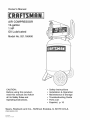
Owner's
Manua_
AiR COMPRESSOR
12-gaHton
1
OiJ Lubricated
Mode_ No. 921.1{$6400
Before using this product,
read this manuan and follow
ati its Safety Runes and
Operating instructions.
o Safety instructions
installation
& Operation
Maintenance
& Storage
Troubleshooting
Guide
Parts List
,, EspaSon,
Sears,
Roebuck
www.sears.com
5/20/2005
Part No. E101338
and Co., Hoffman
Estates,
p. 10
IL 60179
U.S.A.
TABLE OF CONTENTS
Page
Warranty .............................................................
See BeUow
Safety SymboUs...........................................................
1
Umportant Safety Unstructions & Guidelines .....................................
1
Specifications ............................................................
2
GUossary ................................................................
2
Duty Cycle ..............................................................
2
Parts & Features
3
.........................................................
UnstaHation & AssembUy ....................................................
4
Operating Procedures
5
.....................................................
Maintenance .............................................................
6
Storage
6
................................................................
Troubleshooting
Guide .....................................................
7
Expbded View ...........................................................
8
Parts List ...............................................................
9
Espa_oU ................................................................
10
ONE YEAR
FULL WARRANTY
ON CRAFTSMAN
AIR COMPRESSOR
Ufthis Craftsman Air Compressor falls due to a defect in materiaU or workmanship within one
year from the date of purchase, RETURN UTTO ANY SEARS STORE OR PARTS AND REPAIR
CENTER OR OTHER CRAFTSMAN OUTLET UNTHE UNUTED STATES FOR FREE REPAIR,
Ufthis Craftsman Air Compressor is used for commerdaU or rentaU purposes, this warranty
applies for onUy 90 days from the date of purchase, This warranty gives you specific UegaUrights
and you may aUso have other rights which vary from state to state,
Sears, Roebuck and Co., Dept. 817WA,
Hoffman Estates, IL 60179
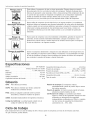
Safety Symbols
The information listed below should be read and understood by the operator, This information is given to protect the
user while operating and storing the air compressor, We utilize the symbols below to allow the reader to recognize
important information about their safety,
indicates an imminently hazardous situation which, if
not avoided, wiii result in death or serious injury,
indicates a potentially hazardous situation which, if not
avoided, may result in minor or moderate injury,
indicates a potentially hazardous situation which, if not
avoided, could result in death or serious injury
When used without the safety alert symbol indicates
a potentially hazardous situation which, if not avoided,
may result in property damage,
mmpottant Safety mnstructions and Guidelines
Save aH instructions
improper operation or maintenance of this product could result in serious injury and/or property damage, Read and
understand all of the warnings and safety instructions provided before using this equipment,
The air compressor should be operated on a dedicated 15 amp circuit, if the circuit
does not have 15 free amps available, a larger circuit must be used, Always use
more air hose before utilizing extension cords, All extension cords used must be 12
gauge with a maximum length of 25 ft, The circuit fuse type must be a time delay, Low
voltage could cause damage to the motor,
Risk of Moving
Parts
if the air compressor is in operation, all guards and covers should be attached or
installed correctly, if any guard or cover has been damaged, do not operate the
equipment until the proper personnel has correctly repaired the equipment, The power
cord should be free of any moving parts, twisting and/or crimping while in use and
while in storage,
Risk of Burns
There are surfaces on your air compressor that while in operation and thereafter can
cause serious burns if touched, The equipment should be allowed time to cool before
any maintenance is attempted, items such as the compressor pump and the outlet
tube are normally hot during and after operation,
Risk of Falling
Operation of the air compressor should always be in a position that is stable, Never
use the air compressor on a rooftop or elevated position that could allow the unit to fall
or be tipped over, Use additional air hose for elevated jobs,
Risk from Flying Objects
r,
i
1
Always wear ANSi Z87,1 approved safety glasses with side shields when the air
compressor is in use, Turn off the air compressor and drain the air tank before
performing any type of maintenance or disassembly of the hoses or fittings, Never
point any nozzle or sprayer toward any part of the body or at other people or animals,
important Safety instructions
& Guidefines
Risk of Breathing
Risk of
E_ectrica_ Shock
Risk of
E×p_osion
or Fire
Risk of Bursting
1
Avoid using the air compressor in confined areas, Always have adequate space
(12 inches) on all sides of the air compressor, Also keep children, pets, and others out
of the area of operation, This air compressor does not provide breathable air for anyone
or any auxiliary breathing device, Spraying material wiii always need to be in another
area away from the air compressor to not allow intake air to damage the air compressor
filter,
Never utilize the air compressor in the rain or wet conditions, Any electrical issues
or repairs should be performed by authorized personnel such as an electrician and
should comply with all national and local electrical codes, The air compressor should
also have the proper three prong grounding plug, correct voltage, and adequate fuse
protection,
Never operate the compressor near combustible materials, gasoline or solvent vapors,
if spraying flammable materials, locate the air compressor at bast 20 feet away from
the spray area, Never operate the air compressor indoors or in a confined area,
Always drain the air compressor tank daily or after each use, if the tank develops a leak,
then replace the air compressor, Never use the air compressor after a leak has been
found or try to make any modifications to the tank, Never modify the air compressor's
factory settings which control the tank pressure or any other function,
Specifications
Pump ..........................
Motor ...........................
Bore .......................................
Stroke ......................................
Voltage Single Phase .......................
Minimum Circuit Requirement ................
Oil-lube direct drive
1,0 HP (induction)
1,65"
1,26"
120 VAC
15 Amps
AirTank Capacity ........................
Cutqn Pressure .............................
Cut-out Pressure ...........................
SCFM @ 90 PSi ................................
Oil Capacity .........................
Oil Type .........................
12 Gallons
95 PSi
125 PSi
2,4
90 mL or 3 oz,
SAE 30 Non-detergent
G ossary
CFM:
Cubic feet per minute,
SCFM: Standard cubic feet per minute; a unit of measure
for air delivery,
PSI¢:
Pounds per square inch gauge; a unit of measure
for pressure,
ASME: American Society of Mechanical Engineers,
California Code: Unit may comply with California Code
462 (I) (2)/(M) (2),
Cut-In Pressure: The air compressor will automatically
start to refill the tank when the pressure drops
below the prescribed minimum,
Cut-Out
Pressure: The point at which the motor stops
when the tank has reached maximum air
pressure,
Code Certification:
Products that bear one or more of
the following marks: UL, ULc, ETL, CSA, have
been evaluated by OSHA-certified independent
safety laboratories and meet the applicable
Underwriters Laboratories Standards for Safety,
Duty Cycle
This is a 50% duty cycle air compressor,
could damage the air compressor,
Do not run the air compressor more than 30 minutes of one hour, Doing so
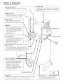
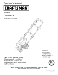
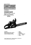
Parts & Features
See figures below for reference,
f
indicates
the reserve
I Tank
Pressure
Gauge air pressure in the tank.
Provides clean air to the pump and must always
be kept free of debris. Check on a daily basis or
Air Intake Filter
}
before each use.
Regulator Gauge
indicates the outgoing air pressure to the
tool and is controlled by the regulator.
Quick Connect
Offers a quick release feature for
attaching and removing the air hose.
Regulator
The air pressure coming from the air
tank is controlled by the regulator,
To increase the pressure, turn the
knob clockwise and to decrease the
@
Oil Fill Cap
pressure turn the knob
counterclockwise,
Tank Safety Valve
Used to allow excess tank pressure
to escape
valve should only open when the
tank pressure is above the
maximum rated pressure.
Sight Gauge
Tube
Pressure Switch
This controls the power to the motor and also
the cutdn/cut-out pressure settings. This switch
serves as the Auto-On/Off positions for the unit.
Pressure Relief Valve
The pressure relief valve, located on
the side of the pressure switch, is
designed to automatically release
compressed air when the air
compressor reaches cut-out
pressure. The released air should
only escape momentarily and the
valve should then close.
Pressure
Relief Tube
Check Valve
When the pump is not in operation, the valve closes to retain
air pressure inside the tank. An internal component.
Installation
& Assembly
The plug must be plugged into an outlet that is properly
installed and grounded in accordance with all local codes
and ordinances, Check with a qualified electrician or
service personnel if these instructions are not completely
understood or if in doubt as to whether the tool is properly
grounded,
The air compressor should be turned off, unplugged from
the power source, the air bled from the tank and the unit
allowed time to cool before any maintenance is performed,
Personal injuries could occur from moving parts, electrical
sources, compressed air or hot surfaces, The quick
connect assembly must be attached before use, Failure
to assemble correctly could result in leaks and possible
injury, if unsure of assembly instructions or you experience
difficulty in the assembly please call our toll free number
for assistance,
installation of the grounding plug wiii result in
a risk of electric shock, if repair or replacement of the
cord or plug is necessary, do not connect the grounding
wire to either fiat blade terminal, The wire with insulation
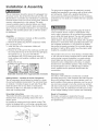
Assembly
1, Remove air compressor, manual, air filter assembly,
and accessories from packaging,
2, Remove the plastic plug from the compressor intake
port, (see diagram below)
3, Install the filter in the compressor intake port,
having an outer surface that is green with or without
yellow stripes is the grounding wire, Check with a qualified
electrician or serviceman if the grounding instructions are
not completely understood, or if in doubt as to whether
the product is properly grounded, Do not modify the plug
provided, if it will not fit the outlet, have the proper outlet
installed by a qualified electrician,
(see diagram be!ow)
4, Remove the oil fiii cap from the crankcase and fiii until
the oil reaches the top of the red dot in the sight glass,
Oil capacity is 3 oz, (seebelow)Use SAE°30
non-detergent (API CG/CD heavy duty motor oil),
Under extreme cold weather conditions use SAE°10
This product is for use on a circuit having a nominal rating
of 120 volts and is factory-equipped with a specific electric
cord and plug to permit connection to a proper electric
circuit, Make sure the product is connected to an outlet
having the same configuration as the plug, An adapter
should not be used with this product, if the product must
be reconnected for use on a different type of electric
circuit, qualified service personnel should make the
reconnection,
weight oil,
5, Replace the oil cap,
Estimated
Assembly
Time: Approximately
5 minutes
Getting Started _ Location of the Air Compressor
The air compressor should always be located in a clean,
dry and well ventilated environment, The unit should have
at minimum, 12 inches of space on each side, The air filter
intake should be free of any debris or obstructions,
Check the air filter on a daily basis to make sure it is
clean and in working order,
Extension Cords
Use only a 3°wire extension cord that has a 3°blade
grounding plug and a 3°slot receptacle that will accept the
plug on the product, Make sure your extension cord is in
good condition, When using an extension cord, be sure to
use one heavy enough to carry the current your product
will draw, Cords must not exceed 25 feet and No, 12 AWG
size must be used, An undersized cord will cause a drop
in line voltage resulting in loss of power and overheating,
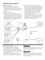
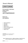
Grounding Instructions
This product should be grounded, in the event of an
electrical short circuit, grounding reduces the risk of
electric shock
Break In Procedures
No break in procedure is required by the user,
This product is factory tested to ensure proper operation
and performance,
by providing an escape wire for the electric current, This
product is equipped with a cord having a grounding wire
with an appropriate grounding plug, (See the figure below,)
Grounded
Outlet
Grounding
Pin
4
Operating
Procedures
Dally Start-Up Procedures
1, Set the Auto-On/Off lever to the Off position,
2, inspect the air compressor, air hose, and any
accessories/tools being used for damage or obstruction,
if any of these mentioned items are in need of repair/
replacement, contact your local authorized service dealer
before use,
3, Close the drain valve,
4, Check the o11[eve[ of the pump,
5, Connect the air hose to the quick connect socket on
the regulator assembly by inserting the quick connect
plug on the air hose into the quick connect socket, The
quick connect socket collar wii[ snap forward and lock
the plug into place providing an air tight sea[ between
the socket and plug, To release the air hose push the
collar back on the quick connect socket,
Daily Shut-Down Procedures
1, Set the Auto-On/Off [ever to the Off position,
2, Unplug the power cord from the receptacle,
3, Set the outlet pressure to zero on the regulator,
4, Remove any air tools or accessories, When draining
the tank, always use ear and eye protection, Drain the
tank in a suitable location; condensation wii[ be present
in most cases of draining,
5, Open the drain valve allowing air to bleed from the
tank, After ai[ of the air has bled from the tank, dose
the drain valve to prevent debris buildup in the valve,
6, Plug the power cord into the proper receptacle,
7, Turn the Auto-On/Off [ever to the On-Auto position and
the compressor wii[ start and build air pressure in the
tank to cut-out pressure and then shut off automatically,
8, Adjust the regulator to a PSi setting that is needed for
your application and be sure it is within the safety
standards required to perform the task, if using a
pneumatic too[, the manufacturer should have
recommendations in the manual for that particular
too[ on operating PSi settings,
9, The air compressor is now ready for use, The following
inflation and cleaning accessories packaged with this
unit should only be operated at maximum pressure
of 90PSi: blow gun, rubber-tapered nozzle, inflation
needles, adapter, and Mow gun adapter,
When draining the tank, always use ear and eye protection,
Drain the tank in a suitable Iocationl condensation wiii be
present in most cases of draining,
Water that remains in the tank during storage will corrode
and weaken the air tank which could cause the tank to
rupture, To avoid serious injury, be sure to drain the tank
after each use or daily,
Maintenance
NOTE: Any service procedure
not covered in the
maintenance schedule should be performed by
qualified service personnel
items to Check/Change
The air compressor should be turned off, unplugged
from the power source, air bled from the tank and
allowed time to coo[ before any maintenance is
performed.
Before each use
or daily
Check Tank Safety Valve
X
Overall Unit Visual Check
X
Check Air Filter
X
Drain Tank
X
Check Power Cord for Damage
X
after first 50 hours
Change Oil
To ensure efficient operation and longer fife of the
air compressor unit, a routine maintenance schedule
should be followed. The following schedule is geared
toward a consumer whose compressor is used in a
normal working environment on a daily basis.
Check Oil Level
after every 100 hours
X
Storage
For storing the air compressor, be sure to do the following:
1, Turn the unit off and unplug the power cord from the
receptacle,
2, Remove ail air hoses, accessories, and air tools from
the air compressor,
3, Perform the daily maintenance schedule,
4, Open the drain valve to bleed ail air from the tank,
5, Close the drain valve,
6, Store the air compressor in a clean and dry location,
Notes
Troubleshooting
Guide
The air compressor should be turned off and unplugged from the power source before any
maintenance is performed as well as the air bled from the tank and the unit allowed time to cook
Personal injuries could occur from moving parts, electrical sources, compressed air, or hot surfaces.
PROBLEM
POSSIBLE
CORRECTION
Air leaks at the check valve
A defective check valve results in a constant air leak at the pressure relief valve
or at the pressure relief valve,
when there is pressure in the tank and the compressor is shut off. Drain the tank,
then remove and clean or replace the check valve.
Air leaks between head and
Be sure of proper torque on head bolts, if leak remains, contact a service technician.
cylinder.
Air leak from safety valve.
Operate the safety valve manually by pulling on the ring. if the valve continues to
leak when in the closed position, it should be replaced.
Pressure reading on the
if there is an excessive amount of pressure drop when the accessory is used,
regulated pressure gauge
replace the regulator.
drops when an accessory is
used.
NOTE:
Adjust the regulated pressure under flow conditions (while accessory is being used).
it is normal for the gauge to show minimal pressure loss during initial use of the
took
Excessive tank pressure.
Move the Auto-On/Off lever to the Off position, if the unit doesn't shut off, unplug it
from the power source and contact a service technician,
Motor wiii not start.
Make sure power cord is plugged in and the switch is on. inspect for the proper size
fuse in your circuit box. if the fuse was tripped, reset it and restart the unit. if
repeated tripping occurs, replace the check valve or contact a service technician.
Excessive moisture in the
Remove the water in the tank by draining after each use. High humidity
discharge air.
environments wiii cause excessive condensation. Utilize water filters on your air
line.
NOTE:
Water condensation
is not caused by compressor malfunction. Be sure the
compressor's air output is greater than your tool's air consumption rate.
Air leaks from the tank body
Never drill into, weld or otherwise modify the air tank or it will weaken. The tank can
or tank welds.
rupture or explode. Compressor cannot be repaired.
compressor.
Discontinue use of the air
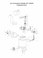
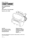
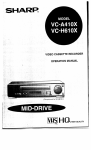
Air Compressor Model 921.166400
Exploded View
e2_
/_49
48_
\
\
_40
46
43__
......
41
- ----14
33
Air Compressor Mode 921.160400
Parts List
Ref,#
PART #
Kit #
QTY,
Ref, #
Screw_socket head, M6 x 1.0 x 30ram
Washer,Lock,6mm
4
8
40
41
Cylinder head
Fitting,9ODeg,3/8" NPT X 3/8" Compression
1
1
42
43
E101037
E100098
I
1
1
Housinq,Air htake Fimter,DieCast
Element,Air Filter
Cover,Air Filter
I
1
1
44
45
46
E101383
2
Gasket, head
1
47
E101491
2
VaHvepilate
Valve,Reed
Gasket,Vaive Hate
2
2
I
48
49
50
Gasket,Cylinder,Upper
Cyiinder,iD 42ram X H 65mm
1
1
51
52
Screw,SHCS,M6 X 1.0 X 20 mm
Gasket,Cylinder,Lower
Motor
7
1
1
1
2
3
4
5
6
7
E100227
E100809
E100435
E101178
8
9
10
I1
12
13
2
E101113
t4
15
16
I7
2
PART DESCRmPTION
1
Drain VaHve,1/4" NPT
Nut,Hex,MlO X 1.25
1
2
¢v'asher,FHat,! Omm
¢_heeH,RedHub
2
2
E101340
BoHt,ShouHder,MlOX 125 X 45 mm
Power Cord, 16/3 X 6',ST
2
1
E100957
NippHe, 1/4" NPT X 1.5"
Pressure switch
1
I
E100094
E100205
53
54
55
daHve,Safety
Pressure Gauge,2",200 PS_
NippHe, 1/4" NPT X 1"
1
I
1
E100059
E100093
ReguHator
Pressure Gauge,l.5",200 PSH
SoupHer,Quick-Connect
1
1
I
E101345
5
5
Tubing Cap, 20ram
HandHe
2
I
5
Rivet Nut, MSXO.8
4
5
Handgrip
$crew,Hex FHangeHead,M5 X 0.8 X lOmm
Shroud,PHastic
Manual
1
6
I
1
3
I
56
57
3
3
Piston Assembly
Ring,Scraper
1
1
58
59
2!
22
3
2, 6
Ring,Compression
Baffle,Rubber
2
1
60
61
Oii Fill Cap
O-rinq, 2mm X 13.5 mm HD
Cover,Crankcase
I
1
1
26
27
4,6
28
4,6
29
30
31
32
33
34
8
8
35
36
8
EI0!362
37
38
7
39
7
7
Screw,Hex FHangeHead,M5 X 0.8 X 15 mm
SeaH,OiH
Sight Gauge
8
1
QTY.
4
2
Nut, M6 X 1.0
Eccentric
6
6
6
PARTDESCRmPTION
4Vasher,FHat,6mm
IsoHator,Rubber
3
E100087
Kit #
Tank
18
19
2O
23
24
25
PART #
E101490
62
E101137
Showf,N°_
E101337
Note: OnHycomponents with a mistedpart/kit number are avaiHaNe. Descriptions
are provided for reference onHy. The Kit # coHumndenotes the components
being offered as part of a kit.
Gauge,OiHSight
Screw,SHCS,M8 X 1.25 X 16mm
t
4
Washer,Lock,8mm
Washer,FHat,8mm
Nut,Hex,M8 X 1.25
4
4
4
NutrCompression,3/8"
FerruHe,Compression,3/8"
Tube,Outlet
Check Valve
2
2
1
1
3
4
5
6
FerruHe,Compression,1/4"
Nut,Compression,l/4"
Pressure RemiefTube
2
2
1
7
8
Description; Reference Numbers
Kit #. Part No,
1
EI01179 Intake fiHterkit; 5, 6, 7
2
E100959 Gasket kit; 8, 11, 12, 15, 22
E100251
E100088
EI01489
E101332
Piston kit; 18, 19, 20, 2!
Sight gauge kit; 27, 28
HandHekit; 57, 58, 59, 60
Crankcase cover kit; 22, 23, 24, 25, 27, 28
E101481 Pressure reHieftube kit; 37, 38, 39
E101480 Outlet tube kit; 33, 34, 35
Contenido
Pagina
Garantia
esta p_.gina
SimboHos de segur[dad
....................................................
11
Instrucciones y pautas de seguridad importantes ................................
11
Especificaciones ..........................................................
12
GIosario ................................................................
12
C[cHode trabajo ..........................................................
12
Partes y caracterist[cas
13
Instalaci6n y ensambiaje
....................................................
...................................................
14
Procedimientos de operaci6n ................................................
15
Mantenimiento
16
...........................................................
AImacenamiento ..........................................................
16
Diagn6stico y correcci6n de fallas ............................................
17
Lista de partes .......................................................
GARANTiA
9
DE UN ANO PARA EL COMPRESOR
DE AIRE CRAFTSMAN
S[ este compresor de a[re Craftsman HHegaa faHHar
deb[do a un defecto de manufactura o de
materiaHes en un pHazo de un a_o, desde Hafecha de compra, DEVU¢:LVALO A LA THENDA
U A OTRO CENTRO CRAFTSMAN 0 CENTRO DE SERVHCHOY PARTES SEARS EN LOS
ESTADOS UNHDOS M,{S CERCANO para que sea reparado sin ningun cargo,
Si este compresor de aire Craftsman se usa con fines comerciales o de renta, esta garantia
unicamente se apiica por 90 dias a partir de Hafecha de compra. Esta garantia Heda derechos
legales especificos; adem6.s, es posibie que usted tenga otros derechos, los cuales varian
segun el estado.
Sears, Roebuck and Co., Dept. 8!7WA,
Hoffman Estates, IL 60179
10
S[mbolos
comunes
de seguridad
El operador debe leer y entender la informaci6n descrita a continuaci6n, Esta informaci6n se ofrece para proteger al
usuario al operar y almacenar el compresor de aire, Los s[mbolos siguientes son los que se utilizan para indicar al lector
informaci6n que es importante para su seguridad,
Indica una situaci6n de riesgo inminente que, al no
protegerse, provocar_ lesiones graves o la muerte.
Indica una situaci6n potencialmente peligrosa que, de no
evitarse, podria provocar lesiones menores o moderadas,
Indica una situaci6n potencialmente peligrosa que, al no
protegerse, podria provooar lesiones graves o la muerte.
Cuando no aparezca sin el simbolo de abrta de seguridad,
6sto quiere decir que hay'una situaci6n potencialmente
peligrosa que, aI no protegerse, podria causar darios
materiales,
lnstrucciones
,, Guarde
todas
y pautas de seguridad
las instrucciones
importantes
,,
La operaci6n y el mantenimiento inadecuados de este producto pueden provocar lesiones graves y daSos materiales.
Antes de utilizar este equipo, lea y entienda las advertencias e instrucciones de seguridad aqui contenidas.
El compresor de aire se debe operar desde un circuito especial de 15 amperios.
Si el circuito no dispone de una capacidad de 15 amperios, se debe usar un circuito de mayor
capacidad. Si es necesario, antes de emplear una extensi6n el@trica, a_ada una manguera de
aire m_s larga. Las extensiones el@tricas deben set de calibre 12 y tenet una Iongitud maxima
de 7,6 metros. El fusible deI circuito debe ser de acci6n
retardada. Un voltaie demasiado baio puede da_ar el motor.
Riesgo por partes
movimiento
en
Riesgo de quemaduras
Riesgo
de ca[da
Riesgo de lanzamiento
de objetos
AI operar el compresor, todos los protectores y cubiertas deben estar fijados e
instalados correctamente. Si alguno de los protectores o cubiertas est_ da_ado,
no opere ei equipo hasta que personal calificado repare ei problema. Ei cable de
corriente debe mantenerse alejado de las partes m6viles del equipo y no debe
torcerse ni prensarse durante su empleo, ni al almacenarse.
En su compresor hay superficies que, al set tocadas durante y despues de su
operaci6n, pueden causar quemaduras graves. Antes de darle mantenimiento al
equipo, se debe dejar enfriar. Pot Io normal, durante y despues de su operaci6n,
ciertas partes como la bomba del compresor y el tubo de salida estar_n calientes.
El compresor siempre debe ser operado en una posici6n estable. Nunca utilice el
compresor sobre un techo o en una posici6n elevada ya que podria caer o
volcarse. AI trabajar en posiciones elevadas, utilice una manguera de aire ma.s larga.
AI emplear el compresor, siempre utilice anteojos de seguridad con protectores
laterales que cumplan con la norma ANSi Z87.1. Antes de llevar a cabo cualquier
clase de mantenimiento y antes de desconectar las mangueras y los acopladores,
apague el compresor y drene el tanque de aire. Nunca apunte la boquilla o el rociador
hacia ninguna parte de su cuerpo, ni el de otros seres.
11
instrucciones
y pautas de seguridad importantes
Evite utHizar eUcompresor de aire en areas encerradas, Sbmpre tenga un espacio
Hbre adecuado (30 cm,) en todos bs UadosdeUcompresor, Tambi6n mantenga fuera
deU_.rea de operaci6n a Uasmascotas, nifios y otras personas, Este compresor de aire
no provee aire que pueda ser respirado ni empbado con un disposWvo respiratorio
auxHiar, EUmateriaU de rociado sbmpre debera estar en otra zona, abjado del
compresor de aire, para evitar que el aire aspirado dafie al filtro del compresor,
Riesgo para la
respiraci6n
Rbsgo de
descargas
electricas
Nunca utilice el compresor de aire bajo Iluvia o en lugares mojados, Los probbmas
el6.ctricos deben ser reparados por personal autorizado, tal como seria un ebctricista,
y deben cumplir con las normas el6ctricas nacionabs y locales, El compresor tambien
debe tener la clavija apropiada de tres terminabs para hacer tierra y contar con
un suministro el6ctrico que sea del voltaje correcto y con un fusible de protecci6n
adecuado,
Riesgo de
e×plosi6n y fuego
Nunca opere el compresor cerca de materiabs combustibles, gasolina ni vapores de
solventes. Siesta rociando materiabs inflamabbs, coloque el compresor a una
distancia de cuando menos 6 metros del _.rea de rociado. Nunca opere el compresor
de aire en interiores o en lugares cerrados.
Riesgo
de estaHido
Drene el compresor diariamente o despu6.s de cada utilizaci6n. Si el tanque tiene una
fuga, reemplace el compresor. Nunca utilice el compresor sise ha detectado una fuga,
ni trate de modificar el tanque. Nunca modifique los ajustes de f6,brica del compresor
que controlan la presi6n del tanque y dem6,s funciones.
!
Especificaciones
Bomba ............................
De impuisi6n
directa, ]ubricada con aceite
Motor ...........................
Diametro ...................................
Carrera ....................................
Capacidad del tanque de aire ...............
45,4 litros
Presi6n de arranque ...............
655,0 KPa / 95 PSi
Presi6n de parada ................
861,8 KPa / 125 PSi
PiescObicosper minute(SCFM)a 90 LPPC.....................
2,4
1,0 HP (Inducci6n)
42 mm
32 mm
Voltaje monof_.sico .........................
Capacidad minima del circuito ...................
Capacidad del aceite ................
120 VAC
Tipo de aceite ..................
15 A
90 ml o 3 onzas,
SAE 30 - no detergente
Glosario
CFM:
Pies cObicos por minuto,
Presi6n
de arranque: El compresor arranca
automaticamente cuando la presidn baja a menos
del minimo prescrito,
Presi6n de parada: El motor se para cuando el tanque
alcance la presi6n maxima de aire,
Certificaci6n
de c6digo: Los productos que tienen
alguna o varias de las siguientes marcas han sido
evaluados pot laboratorios de seguridad
independientes certificados per OSHA, y cumplen
con las normas de seguridad de Underwriters
Laboratories: UL, , ETL, CSA,
SCFM: Pies cObicos est_,ndar por minuto; unidad de
medici6n de suministro del aire,
PSlG: Libras por pulgada cuadrada sobre la presi6n
atmosferica; unidad de medici6n de presi6n,
ASME: Sociedad estadounidense de ingenieros mecAnicos,
C6digo de California: La unidad puede cumplir con el
c6digo de California 462 (I) (2)/(M) (2),
Cicio de traba]o
Este compresor tiene un ciclo de trabajo de 50%, Nunca opere el compresor per mas de 30 minutos cada hora,
Ya que al hacerlo, podria dafiarlo,
12
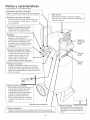
Partes y caracteristicas
Como referencia, vea Uasfiguras abajo.
ManAmetro de presiAn deJ tanque
Indica la presi6n de la reserva de aire del tanque.
FHtro deJ aire
Suministra aire limpio a la bomba. Siempre
debe conservarlo limpio. Reviselo diariamente o
antes de cada uso.
ManAmetro de presiAn de saHda
Undica Uapresi6n de saHda deUaire que entra
en Uaherrambnta, UacuaU que es controUada
per eI reguiador.
Conector de acopJamiento rApido
PermRe conectar y desconectar
rApidamente la manguera deI aire.
Regulador
La presi6n del aire que sale del
tanque es controlada per el
regulador. Para aumentar la presi6n,
gire la perilla en direcci6n de las
manecillas; para disminuirla, gire la
perilla en direcci6n contraria alas
maneciiias.
Tap6n de
Jtenado de
aceite
@
VAlvula de seguridad dei tanque
Permite que el exceso de presi6n en
el tanque escape hacia el medio
ambiente. Esta vAIvula s61o se
abrirA cuando la presi6n en el
tanque este por encima de la
presi6n maxima nominal del modelo.
Visor de
aceite
Tubo de
eaJida
lnterruptor de presiAn
Controla el suministro electrico en el motor y
tambien los ajustes de presi6n de arranque y
presi6n de parada. Este interrupter sirve como
posici6n de autoencendido y apagado (Auto-On/
Oft) de la unidad.
VAJvula de aJivio de presi6n
Esta valvula, que se encuentra en el
costado del interruptor de presi6n,
esta dise_ada para liberar aire
comprimido de manera automatica
cuando el compresor llegue a la
13
Ensamblaje
Antes de reaHzar cuaUqubr instaUaci6n y ensamMaje aU
compresor de aire, se b debe apagar y desconectar deU
generador, ademAs de purgar eUaire deUtanque y darb
suficbnte tbmpo para enfriarse, Exbte eUrbsgo de que
Uaspartes m6vHes, Uafuente eU6ctrica, eUaire comprimido
y Uassuperficies caHentes provoquen bsiones, EUenso
ambb deUreguUador debe estar instaUado antes de usar eU
compresor, Un ensamMaje inadecuado puede ser causa
de fugas y posibbmente de bsiones, Si no esta seguro
de entender Uasinstrucciones de ensambUaje o tbne difio
cultad para Ibvar a cabo el armado, por favor Ilame a su
departamento local de servicio,
Grounded
Ouh'et
Grounding
ebctricista o agente de servicio calificado si no
entiende compbtamente
estas instrucciones, o si
tiene dudas sobre la correcta puesta a tierra de la
herramienta,
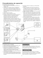
_=nsamblaje
1. Remueva e! compresor de aire, manual, ensambbje del fiRro
de aire y accesorios de la empaquetadura.
2, Remueva el tap6n de plAstico de la salida de aire
del compresor, (ver abajo)
3, Instalar el filtro dentro de la entrada de aire
del compresor, (ver abajo)
4, Remueva la tapa del tanque de aceite del carter
del motor y 116nelohasta Ibgar el punto rojo marcado
en el vidrio transparente, La capacidad de aceite es
3oz (ver abajo), Utilice SAEo30 sin detergente
(API CG/CD aceite para motores de gran capacidad),
En case de fries extremes utilice aceite pesado SAEolO,
5, Coloque nuevamente la tapa del tanque de aceite,
Tiempo estimado
5 minutos
de ensambtaje:
Una conexi6n a tierra inadecuada puede provocar una
descarga electrica, Si necesita reparar o cambiar el cable
o la clavija, no conecte el alambre de tierra a ninguna
de las terminales planas, El alambre de tierra es el de
color verde, con o sin franjas amarillas. Si no entiende
completamente las instrucciones de conexi6n a tierra,
o si tiene dudas sobre la correcta puesta a tierra de
la herramienta, hable con un electricista o agente de
servicio calificado, No modifique la clavija que viene con
el equipo; si no puede enchufarla en el tomacorriente,
llame a un electricista calificado para que le instale el
tomacorriente adecuado,
Este producto estA dise_ado para trabajar en un circuito
con un voltaje nominal de 120 voltios y esta equipado con
un cable y clavija que permiten su conexi6n a un circuito
electrico apropiado, Asegurese de que el producto este
conectado a un tomacorriente con la misma configuraci6n
que la clavija, No se debe usar un adaptador con este
equipo, Si se debe conectar el equipo a un circuito
el6ctrico de diferente tipo, consiga la ayuda de personal
calificado para realizar la reconexi6n,
Aproximadamente
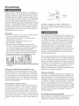
Primer paso: Ubicacidn del compresor de aire
El compresor de aire siempre debe estar en un medio
ambiente limpio, seco y bien ventilado, La unidad debe
tener por Io menos 30 cm de espacio libre en cada lado,
La toma del filtro de aire debe estar limpia y sin ningun
tipo de obstrucciones, Por favor revise diariamente el fib
tro de aire para comprobar que este limpio y en correcto
estado de funcionamiento,
Instrucciones
de conexi6n
Pin
Cables de extensidn
S61o utilice un cable de extensi6n de tres alambres con
una clavija con extensi6n a tierra de tres terminales que
pueda enchufarse en un tomacorriente de tres orificios,
Asegurese de que su cable de extensi6n este en buenas
condiciones, Si utiliza un cable de extensi6n, compruebe
que sea de la capacidad de corriente que requiere su
equipo, Las extensiones no deben ser de mAs de 25 pies
(7,6 m) de largo y deben tener cable de calibre 12 AWG,
Un cable mas delgado provocara una caida en el voltaje
de linea, Io que provocaria una p6.rdida de potencia y
sobrecalentamiento,
a tierra
Este producto se debe conectar a tierra, En caso de
cortocircuito, la conexidn a tierra reduce el riesgo de
descargas el6.ctricas al ofrecer una ruta de escape
para la corriente el6ctrica, Este producto cuenta con
un cable que tiene un alambre de tierra y una clavija
con terminal de tierra (ver la figura a continuacidn), La
clavija debe enchufarse en un tomacorriente instalado
y puesto a tierra segun las normas locales, Habb con
Procedimiento
inicial de preparacidn
No se requiere un procedimiento inicial de preparaci6n,
Este producto ha sido probado en la fAbrica para
asegurar su operaci6n y desempe_o adecuados,
un
14
Procedimientos
de operaci6n
Procedimiento diario de arranque
1. Ponga e[ [nterruptor AutooOn/Often [a pos[c[6n de
apagado (Oft).
2. Vedfique que e[ compresor de[ a[re, [a manguera de
a[re y todos los accesodos/herram[entas utH[zados, no
tengan da_os n[ obstrucc[6n. S[ a[gunas de [as p[ezas
descr[tas requ[eren raparac[6n/reemp[azo, flame a su
t[enda autor[zada local de serv[c[o, antes de usar e[
compresor.
3. C[erre [a vbJvu[a de drenaje.
4. Revise e[ n[ve[ de ace[te de [a bomba.
5. Enchufe [a manguera de[ a[re dentro de[ conector de
acop[amiento rApido de [a unidad de[ regu[ador,
insertando [a c[avija de conexi6n rApida en [a
manguera de[ aire, dentro de[ conector de
acop[amiento r#.pido. El coflarin de[ conector de
acop[amiento r#.pido sa[tara hacia ade[ante, sujetando
la davija y hara una junta entre el conector y la davija.
Para desconectar [a manguera de[ aire, empuje hacia
atr#.s el coflarin de[ conector de acop[amiento r#.pido.
6. Enchufe el cable de corriente en un tomacorriente
apropiado.
7. Mueva el interruptor AutooOn/Offa la posici6n de
encendido (AutooOn); el compresor debera arrancar,
acumu[ando [a presi6n de[ aire en el tanque hasta
flegar a [a presi6n de apagado, momento en el cua[ se
apagar#, de manera automa.tica.
8. Ajuste el regu[ador a [a presi6n de aire recomendada
(PSI) para su apficaci6n, cerciora.ndose de que este
dentro de [as normas de seguridad para flevar a cabo
[a tarea. Para [as herramientas neum6.ticas, el manual
de[ fabricante debe tener recomendaciones sobre su
presi6n de operaci6n (PSI).
9. Ahora el compresor de[ aire est_ fisto para set usado.
Los siguientes accesorios de inflado y de fimpieza, los
cua[es vienen con esta unidad, s6[o se deben operar a
una presi6n maxima de 90 PSI: sop[ete, boquifla c6nica
de caucho, agujas para inflar, adaptador y adaptador de
sop[ete.
Procedimiento
diario de apagado
1. Ponga el interrupter en [a posici6n de apagado (Oft).
2. Desconecte el cable de[ tomacorriente.
3. Ponga en cero el regu[ador de presi6n de sa[ida.
4. Desconecte [as herramientas y los accesorios.
Siempre use protecci6n para los oidos y los ojos a[
drenar el tanque. Drene el tanque en un [ugar
adecuado; en casi todos los cases habr#, presencia de
condensaci6n en el drenaje.
5. Abra [a vA[vu[a de drenaje permitiendo que escape el
aire de[ tanque. Cuando haya safido de[ tanque todo el
aire, cierre [a v6Jvu[a de drenaje para evitar que entre
suciedad.
A[ drenar el tanque uti[ice protecci6n para oidos y ojos.
Drene el tanque en un [ugar apropiado; en [a mayoria de
[as ocasiones a[ drenar sa[dr#, condensaci6n.
Si no drena el tanque a[ a[macenado, en su interior
quedar_, agua que Io corroer#, y debifitara,, Io cual puede
provocar su ruptura. Para evitar [esiones graves, drene el
tanque diariamente o despues de cada uso.
15
Mantenimiento
NOTA: CuaHquierprocedimiento de servicio que no este
cubierto en eHprograma de mantenimiento que sigue
deber_ ser efectuado eHpersonaH de servicio caHficado,
Asuntos
para verificar/
carnbiar
Revisar la vb.lvulade seguridad del
tanque
Antes de dar mantenimiento aHequipo, se debe apagar
y desconectar dell tomacorriente, as[ como purgar eHaire
dell tanque y permitir que Haunidad se enfrie,
A fin de asegurar una operaci6n eficiente y una Harga
vida dell compresor, debe seguir un programa de
mantenimiento de rutina, EHsiguiente programa de
mantenimiento esta enfocado aHconsumidor cuyo
compresor es usado en un medio ambiente normaHy
diariamente,
Antes de cada uso
o diariamente
X
Revisar visuaHmente eHaspecto
generaH de Haunidad
X
Revisar eHfiHtrode aire
X
Drenar eHtanque
X
Verificar que eHcabHe eHectrico
no este daSado
X
Cambiar eHaceite
Verificar eHniveHdell aceite
Despues de las primeras
50 horas
Despues de cada 100
horas
Para aHmacenar eHcompresor, asegurese de hacer Hesiguiente:
1, Apague Haunidad y desconecte eHcame eHectrico dell
tomacorriente,
2, Quite dell compresor Hasmangueras, accesorios y
herramientas de aire,
3, LHevea cabo eHprograma de mantenimiento de rutina,
4, Abra Havb,HvuHa
de drenaje para drenar eHaire dell
tanque,
5, Cierre Hav6,HvuHa
de drenaje,
6, Guarde eHcompresor en un HugarHimpio y seco,
NOTA
16
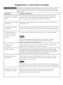
Oiagn6stico
y correcci6n
de fallas
Antes de Ilevar a cabo cualquier correcci6n de probbmas o tarea, el compresor de aire se debe apagar
y desconectar deI tomacorriente, Purgue el aire del tanque y permita que la unidad se enfr[e. Las
partes en movimiento, las fuentes electricas, el aire comprimido y las superficies calbntes pueden
provocar Iesiones.
PROBLEIVlA
POSIBLE CORRECCI6N
Fuga de aire en [a va.[vu[a de
Una v_.ivula de retenci6n defectuosa provoca una fuga de aire constante en [a
retenci6n o en Uav_JvuUade
v6JvuUade aHvio cuando est6. apagado eUcompresor tenbndo
aHvio,
Drene eUtanque y quite y Hmpb o cambb UavaUvuUade retenci6n,
Fugas de aire entre Uacabeza
Compruebe eUaprbte de bs pernos de la cabeza, Si continua la fuga, Ilame a un
y el cilindro,
tecnico de servicio,
Fuga de aire en la valvula
Opere manualmente
de seguridad,
teniendo una fuga estando la v6Jvula en posici6n cerrada, esta deber_ ser cambiada,
La presi6n indicada en el
Si al usar un accesorio hay una ca[da excesiva de presi6n, cambie el regulador,
presi6n de aire,
la valvula de seguridad tirando del anillo, Si el tanque continua
man6metro de presi6n
regulada cae al usar un
accesorio,
Ajuste la presi6n regulada bajo condiciones de fiujo (mientras se utiliza un
accesorio), Es normal que el man6metro indique una caida de presi6n
minima al comenzar a utilizar la herramienta,
Presi6n excesiva
Apague el interruptor de encendido, Si la unidad no se apaga, descon6.ctela del
en el tanque,
tomacorriente y comuniquese
El motor no arranca,
Compruebe que el cable de corriente este enchufado y que el interruptor este
encendido, Compruebe que el fusible de la caja de circuitos sea de la capacidad
adecuada, Si se ha disparado, restablezcalo y vuelva a arrancar la unidad, Si el
con un t6.cnico de servicio,
fusible se dispara con frecuencia llame a un tecnico de servicio,
Humedad excesiva en el
Saque el agua del tanque drenandolo despues de cada vez que se use, En los
aire de salida,
medios ambientes de alta humedad habra, un exceso de condensaci6n; instale
filtros de agua en su linea de aire,
La condensaci6n
no es provocada pot una falla en el compresor, Compruebe que la
salida de aire del compresor sea mayor que el consumo de aire de su herramienta,
Fugas de aire en el cuerpo
Nunca taladre, suelde o modifique de ninguna manera el tanque, pues se
o la soldadura del tanque,
debilitara., El tanque podria romperse o explotar, El tanque no puede set
reparado, Ya no utilice el compresor de aire,
17
Your Home
For repair = in your home = of all major brand appliances,
lawn and garden equipment, or heating and cooling systems,
no matter who made it, no matter who sold it!
For the repWacement parts, accessories and
owner's manuals that you need to do=it=yourself.
For Sears professional installation of home appliances
and items like garage door openers and water heaters.
Call anytime,
(t °800-469-46¢3)
day or night (U.S.A. and Canada)
www.sears.com
www.sears.ca
Our Home
For repair of carry-in items like vacuums, lawn equ;pment,
and electronbs,
calWor go on-line for the location of your nearest
Sears Parts
& Repair
Center.
1o800o488ol 222
Call anytime,
day or night (U.S.A. only)
www.sears.com
To purchase a protection
or maintenance agreement (Canada)
1 °800-827°6655
(U.S.A.)
Para pedir servbio de reparaci6n
a domicilio, y para ordenar piezas:
agreement (U.S.A.)
on a product serviced
by Sears:
1-800-361 °6665 (Canada}
Au Canada pour service en frangais:
1-800=LE-FOYER
Mc
(1-800-553-6937)
(1 °888°784°6427)
www.sears.ca
@ Registered Trademark/ TM Trademark/ SMService Mark of Sears, Roebuck and Co.
@ Marca Registrada/ T_'4 Marca de Fabrica/s MMarca de Servicio de Sears, Roebuck and Co.
MC Marque de commerce/ MDMarque d6pos6e de Sears, Roebuck and Co.
_:_Sears Brands, LLC