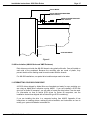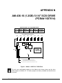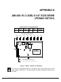
1
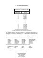
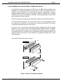
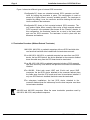
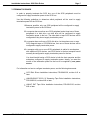
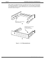
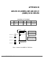
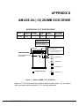
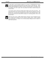
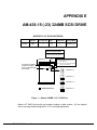
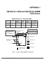
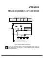
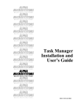
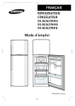
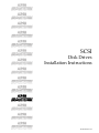
RIGHT. FROM THE START RIGHT. FROM THE START RIGHT. FROM THE START RIGHT. FROM THE START RIGHT. FROM THE START SCSI RIGHT. FROM THE START RIGHT. FROM THE START Disk Drives Installation Instructions RIGHT. FROM THE START RIGHT. FROM THE START RIGHT. FROM THE START RIGHT. FROM THE START RIGHT. FROM THE START RIGHT. FROM THE START RIGHT. FROM THE START PDI-00436-20,Rev.A15 1995 Alpha Microsystems REVISIONS INCORPORATED REVISION 00 01 02 03 04 05 06 07 08 09 10 11 12 13 14 15 DATE Mar. 1990 Apr. 1990 May 1991 July 1991 Aug. 1991 Sept. 1991 Jan. 1992 Apr. 1992 July 1992 Dec. 1992 Jan. 1993 Mar. 1993 Apr. 1993 Sept. 1993 Nov. 1993 Dec. 1993 SCSI Disk Drives Installation Instructions To re-order this document, request part number PDI-00436-20. The information contained in this manual is believed to be accurate and reliable. However, no responsibility for the accuracy, completeness or use of this information is assumed by Alpha Microsystems. This document may contain references to products covered under U.S. Patent Number 4,530,048. The following are registered trademarks of Alpha Microsystems, Santa Ana, CA 92799: AMIGOS AlphaBASIC AlphaLAN AlphaNET CASELODE AMOS AlphaCALC AlphaLEDGER AlphaPASCAL OmniBASIC Alpha Micro AlphaCOBOL AlphaMAIL AlphaRJE VER-A-TEL AlphaACCOUNTING AlphaFORTRAN 77 AlphaMATE AlphaWRITE VIDEOTRAX The following are trademarks of Alpha Microsystems, Santa Ana, CA 92799: AlphaBASIC PLUS DART inFront/am AlphaVUE ESP AM-PC MULTI AMTEC inSight/am All other copyrights and trademarks are the property of their respective holders. ALPHA MICROSYSTEMS 2722 S. Fairview Street P.O. Box 25059 Santa Ana, CA 92799 Installation Instructions: SCSI Disk Drives Page i TABLE OF CONTENTS 1.0 INTRODUCTION . . . . . . . . . . . . . . . . . . . . . . . . . . . . . . . . . . . . . . . . . . . . . . 1 2.0 PRODUCT DESCRIPTION . . . . . . . . . . . . . . . . . . . . . . . . . . . . . . . . . . . . . . 1 3.0 TOOLS REQUIRED . . . . . . . . . . . . . . . . . . . . . . . . . . . . . . . . . . . . . . . . . . . 2 4.0 HANDLING SCSI DISK DRIVES . . . . . . . . . . . . . . . . . . . . . . . . . . . . . . . . . . 2 5.0 CONFIGURING YOUR SCSI DISK DRIVE . . . . . . . . . . . . . . . . . . . . . . . . . . 2 6.0 SCSI TERMINATION USING EXTERNAL TERMINATOR OPTION . . . . . . 3 6.1 Termination Procedure (Without External Terminator) . . . . . . . . . . . 4 7.0 TERMINATOR POWER . . . . . . . . . . . . . . . . . . . . . . . . . . . . . . . . . . . . . . . . 5 8.0 SCSI DRIVE INSTALLATION (AM-1400/1600 COMPUTERS) . . . . . . . . . . . 6 8.1 Getting Started . . . . . . . . . . . . . . . . . . . . . . . . . . . . . . . . . . . . . . . . . . 6 9.0 SCSI 3-1/2" DRIVES IN 5-1/4" MOUNTING CONFIGURATIONS . . . . . . . . 7 9.1 3-1/2" SCSI Drives in Series 90 Computers . . . . . . . . . . . . . . . . . . . 10 10.0 ISOLATING SIGNAL AND CHASSIS GROUNDS . . . . . . . . . . . . . . . . . . . . 10.1 Testing for AC to DC Ground Shorts Using an Ohm Meter . . . . . . . . 10.2 Drive Isolation (AM-1400/1600 Computers) . . . . . . . . . . . . . . . . . . . 10.3 Drive Isolation (Pedestal and Rack Mount Computers) . . . . . . . . . . . 10.4 Drive isolation (AM-990 Universal VME Enclosure) . . . . . . . . . . . . . 11.0 FORMATTING YOUR SCSI DISK DRIVE . . . . . . . . . . . . . . . . . . . . . . . . . . . 15 APPENDIX A - CONFIGURING AMOS SCSI DISK DRIVES A.1 BOOTING FROM A SCSI DRIVE (AMOS ONLY) . . . . . . . . . . . . . . . A.1.1 Loading the Software . . . . . . . . . . . . . . . . . . . . . . . . . . . . . . . A.1.2 SCSI Drivers . . . . . . . . . . . . . . . . . . . . . . . . . . . . . . . . . . . . . A.1.3 MONGEN the Monitor . . . . . . . . . . . . . . . . . . . . . . . . . . . . . . A.1.4 System Initialization Command File . . . . . . . . . . . . . . . . . . . . A.1.5 Ready to Boot . . . . . . . . . . . . . . . . . . . . . . . . . . . . . . . . . . . . A.2 INITIAL SYSTEM TESTING . . . . . . . . . . . . . . . . . . . . . . . . . . . . . . . A.3 OTHER DOCUMENTATION . . . . . . . . . . . . . . . . . . . . . . . . . . . . . . . PDI-00436-20, Rev. A15 11 11 13 14 15 A-1 A-1 A-3 A-3 A-3 A-4 A-5 A-6 Page ii Installation Instructions: SCSI Disk Drives APPENDIX B - AM-436-20 (40MB) AND AM-436-21 (80MB) SCSI DRIVES APPENDIX C - AM-436-25 (-01) 120MB SCSI DRIVE APPENDIX D - AM-436-24 (-13) 203MB SCSI DRIVE APPENDIX E - AM-436-15 (-23) 324MB SCSI DRIVE APPENDIX F - AM-436-20 (-00) 40MB AND AM-436-21 (-11) 80MB SCSI DRIVES APPENDIX G - AM-436-20 (-00) 40MB AND AM-436-21 (-11) 80MB SCSI DRIVES APPENDIX H - AM-436-29 (-19) 234MB AND AM-436-26 (-14) 203MB SCSI DRIVES APPENDIX I - AM-436-30 (-18) 324MB SCSI DRIVE APPENDIX J - AM-436-44 1.2GB AND AM-436-45 540MB SCSI DRIVES APPENDIX K - AM-436-06 (330MB) 5-1/4" SCSI DRIVE APPENDIX L - AM-436-08 (638MB) 5-1/4" SCSI DRIVE APPENDIX M - AM-436-08 (638MB) 5-1/4" SCSI DRIVE APPENDIX N - AM-436-16 (1.2GB) 5-1/4" SCSI DRIVE (PCBA# 1027614) APPENDIX O - AM-436-16 (1.2GB) 5-1/4" SCSI DRIVE (PCBA# 1027341) PDI-00436-20, Rev. A15 Installation Instructions: SCSI Disk Drives Page 1 1.0INTRODUCTION This document describes the installation of both 3-1/2" and 5-1/4" SCSI disk drives into an Alpha Micro computer. It is written for the experienced Alpha Micro Service Technician, so if you do not feel comfortable performing the hardware and software procedures discussed in this document, please contact your Alpha Micro Dealer or the Alpha Micro Technical Support Group for help. Installing a SCSI disk drive is simply a matter of placing the drive inside your computer chassis, connecting the appropriate power and interface cables, and configuring the correct software. Those wishing to install a SCSI drive into an external subsystem should refer to the installation instructions for the AM-1601 Subsystem, PDI-01601-00, or the SCSI Universal Subsystem, PGI-00001-00. This document contains information for each SCSI disk drive currently sold and supported by Alpha Micro. This information includes drive addressing, terminator locations, and other items unique to the various drive manufacturers. 2.0PRODUCT DESCRIPTION The SCSI disk drive package consists of a SCSI disk drive and mounting kit. The following table shows the storage capacity and the order number for SCSI drives currently available from Alpha Micro: DRIVE CAPACITY DRIVE SIZE PART NUMBER for ordering 120MB 3-1/2" PDB-00436-25 213MB 3-1/2" PDB-00436-26 (-14) 245MB 3-1/2" PDB-00436-29 (-19) 345MB 3-1/2" PDB-00436-30 (-18) 540MB 3-1/2" PDB-00436-45 1.2GB 3-1/2" PDB-00436-44 PDB-00436, (-44), (-45), (-14), (-18), and (-19) 3-1/2" disk drive kits are shipped with a special 5-1/4" mounting bracket. These kits are applicable for Alpha Micro products that support 5-1/4" SCSI disk drives, including Series 90 Computers. PDI-00436-20, Rev. A15 Page 2 Installation Instructions: SCSI Disk Drives 3.0TOOLS REQUIRED For most installations, the only tools you will need are: A #2 phillips-head screwdriver. A pair of needle-nose pliers, used for removing or installing SCSI drive ID jumpers. An ohm meter, used to verify the signal ground on the disk drive is not shorted to chassis ground (not required in Series 90 Applications). 4.0HANDLING SCSI DISK DRIVES Disk drives can be damaged easily when handled improperly: 1.Leave the SCSI drive in the anti-static bag it was shipped in until you are ready to install it. 2.Never handle a disk drive unless you are properly grounded. This will prevent a static charge from damaging the drive before you even have it installed. 3.Disk drives are extremely sensitive to shock, especially when handled outside the system environment. When setting a drive on a work bench, exercise extreme caution; whenever possible try to set the drive on a padded anti-static surface. 5.0CONFIGURING YOUR SCSI DISK DRIVE There is a separate appendix for each manufacturer/model of SCSI drive sold and supported by Alpha Micro in the back of this document. The drives are shown with their jumpers configured as shipped from the factory. You should carefully go over the information applicable to the SCSI drive you are installing. The illustrations also highlight the differences in jumper configurations between AMOS and Series 90 applications. Most of the configuration information shown in the table above each disk drive is applicable only when the drive is used with the AMOS operating system. The "number of logicals", "bitmap size", and "format interleave" specifications are not applicable to Series 90 computers. SCSI disk drives used in AMOS 680X0 based computers must be installed with the drive’s signal ground isolated from the computer’s chassis ground. Before installing your new disk drive, see Section 10 (in this document) dealing with drive isolation in AMOS based products. PDI-00436-20, Rev. A15 Installation Instructions: SCSI Disk Drives Page 3 6.0SCSI TERMINATION USING EXTERNAL TERMINATOR OPTION The preferred method of terminating the SCSI bus in an AMOS based computer is the installation of an external terminator. In Early April of 1993, the external SCSI bus terminator became standard on all AMOS based computer configurations. Using an external terminator makes the task of installing an add-on subsystem (like a portable CD-ROM drive) easier, eliminating the necessity of removing terminators from a SCSI device located in the host computer. External terminators are available from Alpha Micro under part number PRA-00222-00. To use the external terminator, you need to insure none of your SCSI peripherals inside the computer are terminated. You will also need to follow the guidelines in the section on providing termination power for the SCSI bus. If you have a 10 or 21-slot rack mount VME computer and want to install an external terminator, you will need to order a special adapter cable, DWB-10200-01. The adapter cable is required, because there is no external SCSI connector on these computers. The special cable has a connector that is compatible with the external terminator and would also allow easy access to your computer for a portable CD-ROM drive or other SCSI subsystem. The external terminator is shown in Figure 1: BAIL LOCKS CONFIGURATION A SI SC (PRA-00222-00) EXTERNAL SCSI BUS TERMINATOR CONFIGURATION B SI SC MAC821 #4 SCREW AND WASHER Figure 1. External Terminator Installation PDI-00436-20, Rev. A15 Page 4 Installation Instructions: SCSI Disk Drives Figure 1 shows two different types of external SCSI connectors. 1.Configuration"A" shows an extended external SCSI connector and bail locks for holding the terminator in place. This configuration is used on almost all of Alpha Micro’s currently available product. The terminator is installed by sliding it over the connector and then latching the bail locks into the notches in the terminator. 2.Configuration"B" shows a flush mounted external SCSI connector. The only product Alpha Micro currently offers using a flush mounted external SCSI connector is the pedestal (also known as the "Classic") chassis. In this configuration, the terminator inserts into a cutout in the sheet metal and over the SCSI connector. The terminator is held in place with two #4screws and washers. 6.1Termination Procedure (Without External Terminator) 1.AM-14XX, AM-16XX, or pedestal computers with one SCSI hard disk drive can have that hard disk drive installed with its terminators removed. 2.If an AM-14XX, AM-16XX, or pedestal computer has more than one SCSI device, the last SCSI device, the device attached to the connector farthest down the cable away from the CPU board must be terminated. 3.If an AM-14XX, AM-16XX, or pedestal computer includes a SCSI magnetic tape drive as its only SCSI device, the tape drive must have its terminators installed. 4.For AM-990, 10-slot rack mount VME, and 21-slot rack mount VME computers, the last SCSI device attached to the connector farthest down the cable away from the CPU board must have its terminators installed. If only one SCSI device is installed, that device must be terminated. 5.For subsystem installations, the last SCSI device attached to the connector farthest down the cable away from the host computer must have its terminators installed. AM-1000 and AM-1200 computers follow the same termination procedure used by AM-14XX, AM-16XX, and pedestal computers. PDI-00436-20, Rev. A15 Installation Instructions: SCSI Disk Drives Page 5 7.0TERMINATOR POWER In order to properly terminate the SCSI bus, one of the SCSI peripherals must be configured to supply termination power to the SCSI bus. Use the following guidelines to determine which peripheral will be used to supply termination power for the SCSI bus: 1.Whenever possible, only one SCSI peripheral will be configured to supply termination power to the SCSI bus. 2.If a computer has more than one SCSI peripheral and at least one of those peripherals is a disk drive, one disk drive will be configured to supply termination power to the bus. The other disk or tape SCSI devices will be configured so they do not supply termination power. 3.If a computer does not have a SCSI disk drive, but does have one or more SCSI magnetic tape or CD-ROM drives, then one of these devices will be configured to supply termination power. 4.If a computer with one or more SCSI peripherals is cabled to a subsystem with additional SCSI devices, one SCSI device in the host computer would normally be configured to supply termination power for the bus. You should avoid having a SCSI device in both the host computer and the subsystem configured to supply termination power. Ideally, you want the source of the termination power for the bus to be supplied by one power source. For information on how to configure terminator power, see the following documents: SCSI Disk Drives Installation Instructions, PDI-00436-20, revision A12 or later. AM-625/626/627 SCSI 1/4" Streaming Tape Drive Installation Instructions, PDI-00625-00, revision A05 or later. AM-647 DAT Tape Drive Installation Instructions, PDI-00647-00, revision A02 or later. PDI-00436-20, Rev. A15 Page 6 Installation Instructions: SCSI Disk Drives 8.0SCSI DRIVE INSTALLATION (AM-1400/1600 COMPUTERS) This section details how to install a replacement 3-1/2" SCSI drive into your AM-1400 or AM-1600 computer. AM-1400 and AM-1600 computers do not require a 5-1/4" mounting bracket. SCSI disk drives used in AM-1400/1600 computers must be installed with the drive’s signal ground isolated from the computer’s chassis ground. Before installing your new disk drive, see Section 10 (in this document) dealing with drive isolation. 8.1Getting Started The first step in the installation process is to remove the computer top cover. The top cover is held in place with four phillips-head screws, two on each side. After you have removed the screws, lift off the top cover and place it in a safe spot. The next step is to remove the drive mounting bracket from the chassis. This bracket is held in place with four phillips-head screws. The screw locations are shown in Figure 2, called out as A, B, C, and D. B DRIVE MOUNTING BRACKET A D C MAC215 Figure 2 Once you have taken out the screws, remove the drive mounting bracket from the computer chassis. This will expose the mounting brackets that support the SCSI 3-1/2" disk drive. The drive is held in place with four screws, two on each side. Maxtor disk drive product kits include special drive mounting brackets that must be used for AM-1400/AM-1600 installations. The contents of these kits vary depending on the drive model. Read the appendix information for the drive you are installing for information on special brackets and mounting instructions. PDI-00436-20, Rev. A15 Installation Instructions: SCSI Disk Drives Page 7 If your old SCSI drive is still in place, remove the four screws that attach the drive to the mounting brackets and remove the drive from the enclosure. Before installing your new drive, take a look at the mounting brackets that support the 3-1/2" SCSI drive. The brackets should have some insulating material on the inside edges where the drive and the mounting bracket make contact. The purpose of this insulating material is to prevent the shorting together of AC and DC grounds through the drive’s HDA. If your mounting brackets do not have this insulating material, part# DWF-20526-00, the insulating material is included in drive mounting kits designed for AM-1400/1600 installations. Before sliding your new drive into place, make sure the drive is addressed correctly. Plug the 50-pin interface cable into the drive, making sure the red stripe on the cable aligns with pin-1 on the drive’s connector. There is a sticker affixed to the top of the drive’s HDA cover that points to the pin-1 location: PIN 1 ------> Plugging the 50-pin interface cable in backwards can damage the drive. Plug the 4-pin power cable into the drive. This connector is keyed so you can’t go wrong. Re-install the top cover. 9.0SCSI 3-1/2" DRIVES IN 5-1/4" MOUNTING CONFIGURATIONS Most of Alpha Micro’s computers (including Series 90) are designed for 5-1/4" SCSI disk drives. Alpha Micro has several mounting brackets available that allow a 3-1/2" SCSI drive to be mounted in 5-1/4" configurations. SCSI disk drives used in AMOS 680X0 based computers must be installed with the drive’s signal ground isolated from the computer’s chassis ground. Before installing your new disk drive, see Section 10 (in this document) dealing with drive isolation. The PRF-00113-10 bracket, shown at the top of Figure 3, is designed for second drive applications in AM-1400/1600 computers and AM-1601 subsystems. This bracket is compatible with both Quantum and Maxtor 3-1/2" drives. The bracket shown at the bottom of Figure 3 (DWB-00113-20) includes a 5-1/4" front bezel and is used with Maxtor 3-1/2" drives only. There is similiar bracket available for Quantum 3-1/2" drives, its part number is PRF-00113-00. PDI-00436-20, Rev. A15 Page 8 Installation Instructions: SCSI Disk Drives When ordered as independent demand, the PRF-00113-00 and (-20) mounting brackets are shipped unassembled. For most applications the 5-1/4" front bezel is not required. If your application does not require a front bezel, all you need to do is attach the rails to the drive as shown in Figure 4. PRF-00113-10 3-1/2" SCSI DRIVE MOUNTING BRACKET. PRF-00113-20 3-1/2" SCSI DRIVE MOUNTING BRACKET. (INCLUDES FRONT BEZEL) MAC4 3 4 Figure 3 — 5-1/4" Mounting Brackets PDI-00436-20, Rev. A15 Installation Instructions: SCSI Disk Drives Page 9 A 3-1/2" SCSI drive is installed in the bracket as shown in Figure 4. The drive is held in place with four screws, two in each side. The illustration shows the drive being mounted in the DWB-00113-10 bracket, but the procedure is virtually the same for all mounting brackets. PRF-00113-10 3-1/2" SCSI DRIVE MOUNTING BRACKET. 3 1/2" SCSI DISK DRIVE MOUNTING POSITION MAC4 3 2 Figure 4 — 5-1/4" Mounting Brackets Once the drive is installed in the bracket, it is compatible with all VME, AM-2000M, AM-3000M, and AM-960 Series 90 5-1/4" disk drive mounting configurations. PDI-00436-20, Rev. A15 Page 10 Installation Instructions: SCSI Disk Drives 9.13-1/2" SCSI Drives in Series 90 Computers Series 90 computers also require 5-1/4" mounting brackets in order to mount 3-1/2" SCSI disk drives. For Series 90 AM-940, AM-980, and AM-990 computers, the drive is installed in the bracket as previously described, but the addition of two plastic mounting rails is required to be Series 90 compatible. These two plastic rails are held in place with two screws as shown in Figure 5. Plastic rails are not required for the AM-960 Series 90 computer. Once the drive is installed in the 5-1/4" mounting frame, it attaches to the AM-960 peripheral mounting area with four screws, two on each side. HDM-00106-01 MOUNTING RAIL - LEFT HDM-00106-00 MOUNTING RAIL - RIGHT 3 1/2" SCSI DISK DRIVE MOUNTING POSITION MAC4 3 3 Figure 5 Once the rails are installed, the drive slides into place inside your computer chassis. After the drive is installed in the chassis, install the two metal clips used to keep the drive from sliding forward from its mounting position. Plug the 50-pin interface cable into the drive, making sure the red stripe on the cable aligns with pin-1 on the drive’s connector. There is a sticker affixed to the top of the drive’s HDA cover that points to the pin-1 location: PDI-00436-20, Rev. A15 Installation Instructions: SCSI Disk Drives Page 11 PIN 1 ------> Plugging the 50-pin interface cable in backwards can damage the drive. Plug the 4-pin power cable into the drive. This connector is keyed so you can’t go wrong. 10.0ISOLATING SIGNAL AND CHASSIS GROUNDS For all AMOS 680X0 applications it is important to prevent the disk drive’s DC (signal) ground from being shorted to the computer’s AC (chassis) ground. Alpha Micro’s SCSI drive mounting kits contain the necessary hardware used to isolate the drive from chassis ground. However, you should not be concerned if your drive installation kit does not contain any of the drive isolation accessories described in the next few sections. Some disk drives, due to the nature of their design, do not require any special isolation hardware. You can be certain your drive is properly isolated by using an ohm meter as described in the next section. In Series 90 installations, the isolation of signal ground and chassis ground is not required and is not a problem. 10.1Testing for AC to DC Ground Shorts Using an Ohm Meter Using an ohm meter is the only way to insure you have properly isolated your disk drive from chassis ground. We highly recommend that you use an ohm meter to verify your installation, using the following instructions: 10 OH 0K MS 0 MAC782 PDI-00436-20, Rev. A15 Page 12 Installation Instructions: SCSI Disk Drives Checking Individual Peripherals for Shorts to Chassis Ground 1.To determine if a peripheral is shorted to chassis ground, disconnect the peripheral’s power and interface cables, but do not loosen or remove any of the peripheral’s mounting hardware. Use an ohm meter to measure between chassis ground and either of the two middle pins on the peripheral’s power connector. The power connector has four pins; the two outside pins are power; the two inside pins are ground. PERIPHERAL DC POWER CONNECTOR +5V GND GND +12V MAC785 2.If you measure less than 100k ohms between chassis ground and one of the ground pins on the peripheral’s power connector, you have located a problem that needs to be corrected. Here are a couple of things to check for: a.The four screws attaching the peripheral to its mounting brackets may be too long. If the screws extend too far into the peripheral they can come in contact with the peripheral’s signal ground, creating a direct path to chassis ground. b.In AM-1400 and AM-1600 computers, if the disk drive mounting brackets do not have adhesive lexan insulating strips (DWF-20526-00), it is possible for the drive’s signal ground to be shorted to the metal mounting brackets. c.The rotating disks and read/write heads inside your disk drive are encased in a metal enclosure called the HDA (Head Disk Assembly). The HDA assembly is tied to the drive’s signal ground. If the HDA assembly makes metal to metal contact with the drive mounting brackets in your computer, an AC to DC ground loop may result in applications where the mounting brackets are directly attached to the computer’s metal chassis. d.Review all the mounting procedures discussed in sections 8.X. There is a separate section for each type of applicable Alpha Micro computer model. PDI-00436-20, Rev. A15 Installation Instructions: SCSI Disk Drives Page 13 10.2Drive Isolation (AM-1400/1600 Computers) In AM-1400 and AM-1600 computers, 3-1/2" SCSI disk drives are installed as described in Section 6. Unlike most of the other applications, no 5-1/4" mounting bracket is required for AM-1400/1600 computers. The disk drive mounting brackets in AM-1400/1600 computer’s have adhesive insulating strips (DWF-20526-00), that when used in conjunction with nylon screws, prevent the drive’s signal ground from being shorted to chassis ground. The nylon screws have a metal insert which greatly increases their strength. See Figure 6. Some early model AM-1400/1600 3-1/2" drive mounting brackets do not have the adhesive insulating strips. Therefore, two of the insulating strips are included in drive installations kits designed for AM-1400/1600 use. HDS-11806-04 NYLON SCREW METAL WASHER MAC783 METAL INSERT Figure 6. Drive Installation Screw If you are installing a 3-1/2" drive that is 1-3/4" thick, it is possible for the drive to come in contact with the chassis bottom. In some cases, by lifting the drive up before you tighten the mounting screws, you can prevent the drive from making contact with the chassis bottom. Your success at doing this can be verified with an ohm meter. Alpha Micro supplies a special isolator (DWF-20525-01) for installing 3-1/2" SCSI drives thicker than 1". It is a piece of clear mylar designed to completely wrap around the drive. The isolator has a self-adhesive strip that comes together around the drive as shown in Figure 7. PDI-00436-20, Rev. A15 Page 14 aa Installation Instructions: SCSI Disk Drives This isolator is used in AM-1400/1600 applications for mounting 1-3/4" thick 3-1/2" SCSI disk drives. DWF-20525-01 Self-Adhesive Strip a MAC687 Figure 7 The isolator has two sets of holes, allowing both Quantum or Maxtor drives to be used. Once the isolator is positioned around the drive, it can be placed in its mounting position inside the chassis. The drive will be held in place using four nylon screws and metal washers as shown in Figure 6. 10.3Drive Isolation (Pedestal and Rack Mount Computers) In pedestal and rack mount enclosures, the drive (or drives) sit on a plastic mounting base and attach to a plastic front bezel; because of the way the drive is mounted, it would appear to be fully isolated from chassis ground. However, because the front bezel has a conductive coating, the drive can still be shorted to chassis ground at the point where it attaches to the front bezel. The use of two nylon shoulder washers (HDW-10004-07) will insure that the drive will not be able to make electrical contact with the coating on the front bezel. These washers are used as shown in Figure 8 and install exactly the same way on both pedestal and rack mount computers. PDI-00436-20, Rev. A15 Installation Instructions: SCSI Disk Drives Page 15 FRONT BEZEL NYLON SHOULDER WASHERS (HDW-10004-07) METAL SUPPORT BRACKET DWF-20260-00 SCSI DISK DRIVE MAC688 Figure 8 10.4Drive isolation (AM-990 Universal VME Enclosure) Disk drives mount inside the AM-990 chassis using plastic slide rails. One rail installs on each side of the peripheral. Because the mounting rails are made of plastic, they prevent the drive from making metal to metal contact with the chassis. For AM-990 installations, no special drive isolation steps need to be taken. 11.0FORMATTING YOUR SCSI DISK DRIVE All SCSI drives shipped by Alpha Micro are formatted and ready for use, providing you are using an Alpha Micro computer running AMOS. If you are installing a SCSI disk drive into a Series 90 computer, you will need to format the drive before it can be used. For information on how to format SCSI drives for Series 90 computers, see the installation instructions shipped with a Series 90 type SCSI controller(s). If you are installing the drive in a computer booting from AMOS, Appendix A has instructions on creating drivers; making the drive bootable; and instructions on how to modify your system initialization command file. PDI-00436-20, Rev. A15 Page 16 Installation Instructions: SCSI Disk Drives Under AMOS 2.2 (or later) operating systems, you can divide your hard disk drive into logical splits larger than 32MB. In fact, you could take a 540MB drive and make it one giant 540MB logical. While this is perfectly acceptable, you may get a memory allocation error when running programs that load a copy of the bitmap into your memory partition—e.g., DSKANA and MONTST. To use these types of programs, you will need at least one job on your computer with enough memory allocated to allow you to load the large bitmap. Depending on the size of the logical device, you may need a memory partition between 100 and 800KB. PDI-00436-20, Rev. A15 APPENDIX A CONFIGURING AMOS SCSI DISK DRIVES A.1BOOTING FROM A SCSI DRIVE (AMOS ONLY) This section describes the process of making your new SCSI drive bootable. Your drive was formatted by Alpha Micro prior to shipment, therefore the procedure for formatting the drive is not discussed. However, the SCSI drive format program, FMTSCZ, is described in detail in Alpha Micro’s System Commands Reference Manual. A.1.1Loading the Software The first step towards making your SCSI drive bootable is to download the operating system. The easiest way to download the software is to create a bootable VCR tape. If your system has an optional floppy disk drive, this is also a good way to transfer software onto your new drive. Bootable VCR Tape: In the illustrations showing the SCSI disk drive jumper configurations, there is a table showing the number of logicals and the bitmap size for each drive. Although the bitmap size is not used when configuring the system initialization command file, the bitmap size is needed when making a bootable WRMGEN file. You can use this information to make a WARMBOOT tape for loading software on your new SCSI drive. For example, let’s say you are replacing your 40MB drive with a larger capacity 80MB SCSI disk drive with three logicals. Let’s also assume the 40MB drive is still operational. To create a WARMBOOT monitor that is compatible with your new 80MB drive, follow the steps outlined below: LOG SYS: RETURN WRMGEN 80MB.WRM RETURN Input monitor name: AMOSL.MON RETURN PDI-00436-20, Rev. A15 Page A-2 Configuring AMOS SCSI Disk Drives System disk driver: SCZDVR.DVR RETURN Number of logical units: 3 RETURN Bitmap size: 3413 RETURN Language definition table: ENGLSH RETURN System terminal interface driver: AM130 RETURN System terminal interface port number: 0 RETURN System terminal interface baud rate: 9600 RETURN Enter number of SECONDARY DEVICE(S) to be defined into system, one per line. Enter blank line to terminate loading. Program to load: /VCR0 RETURN Program to load: RETURN Enter names of program(s) to be loaded into SYSTEM MEMORY, one per line. Enter blank line to terminate loading. Program to load: VCR.DVR[1,6] RETURN Program to load: VCRRES.LIT RETURN Program to load: VCRDIR.LIT RETURN Program to load: VCRSAV.LIT RETURN Program to load: SCNWLD.SYS RETURN Program to load: SYSMSG.USA RETURN Program to load: CMDLIN.SYS RETURN Program to load: LOG.LIT RETURN Program to load: DIR.LIT RETURN Program to load: RETURN Enter name of program(s) to be loaded into USER PARTITION, one per line. Enter a return to terminate loading. Program to load: RETURN ** Warm boot generation complete. Warm boot monitor is 88736 bytes ** Now that you have created your WARMBOOT monitor, you will be able to make a bootable tape, type: LOG OPR: RETURN VCRSAV ALL:*.*[]/B RETURN Input Warm Boot file name: 80MB.WRM RETURN Volume name: BOOT TAPE RETURN Volume I.D.: AMOS/LC 1.3X RETURN Installation: IN-HOUSE RETURN System: AM-1400LC RETURN Creator: John Doe RETURN PDI-00436-20, Rev. A15 Configuring AMOS SCSI Disk Drives Page A-3 All other user will users will be suspended while VCRSAV is running. Enter RETURN to continue or CTRLC to abort: RETURN The tape you have created will be compatible with your new 80MB SCSI disk drive. Once you have installed your new drive, use your WARMBOOT tape to boot your new drive. To restore the software enter the following command: VCRRES ALL:*.*[]=ALL:*.*[] RETURN A.1.2SCSI Drivers It is not necessary to create a special boot driver for SCSI drives using FIXLOG. There is a generic SCSI driver in account [1,6] that is used for creating SCSI bootable AMOS Monitors, SCZDVR.DVR. A.1.3MONGEN the Monitor Use the MONGEN program to embed the appropriate SCSI driver in the AMOS monitor located in account [1,4] on your SCSI drive: Example: Enter: MONGEN RETURN Input monitor name: LSYS.MON RETURN New disk driver: SCZDVR.DVR RETURN New language definition table name: ENGLSH RETURN New monitor name: AMOSL.MON RETURN Enter: SAVE AMOSL.MON RETURN A.1.4System Initialization Command File The System Initialization Command File (AMOSL.INI) for SCSI drives is easy to setup, due largely to the self-configuring nature of the SCSI drive. PDI-00436-20, Rev. A15 Page A-4 Configuring AMOS SCSI Disk Drives Example: :T JOBS 1 JOBALC JOB1 ; TRMDEF TERM1,AM130=0:19200,AM62A,100,100,100 ; DEVTBL DSK1,DSK2 DEVTBL TRM,RES,MEM DEVTBL /VCR0 ; BITMAP DSK,,0,1,2 ; ERSATZ ERSATZ.INI ; SYSTEM CMDLIN.SYS SYSTEM SYSMSG.USA SYSTEM MOUNT.LIT SYSTEM ; SET GUARD SET DSKERR SET HEX ; MOUNT DSK1: MOUNT DSK2: ; VER MEMORY 0 Note that no Bitmap size was allocated in the sample Initialization file above. Self-configuring drives do not require pre-allocating a bitmap size. However, double commas must be inserted in the BITMAP statement, as shown in the prior example. The sample initialization file has a SCSI drive defined with three logicals; make sure you configure your initialization file with the number of logicals that corresponds to the SCSI drive you are installing. A.1.5Ready to Boot If you have completed all the steps above, it’s time to press the reset button. This is the part where you may feel a little nervous, wondering if you made any errors in configuring the software on your drive. The safest method, before you press the reset button, is to be certain that you have some way of accessing your system in case it doesn’t boot. The ideal situation is being able to boot from another peripheral on the system, but if that’s not possible make sure you have a bootable VCR or streamer tape available. PDI-00436-20, Rev. A15 Configuring AMOS SCSI Disk Drives Page A-5 After booting from the SCSI drive perform the initial system testing procedure outlined in the next section. A.2INITIAL SYSTEM TESTING Once the computer has successfully booted, it’s time to test your newly installed SCSI disk drive. Use the SYSTAT command to determine the current status of your newly installed SCSI drive, type: SYSTAT RETURN Observe the terminal display and check the status of both the newly installed SCSI drive and the primary disk drive. Example: Total memory on the system is 2M bytes System uptime is 00:05:06 DSK0 47667 Blocks free DSK2 56622 Blocks free DSK1 56622 Blocks free Make sure that each of the logical devices on your new disk drive is correctly displayed on the screen. The number of blocks on the DSK0 device will be less than the other logical devices, because that’s where the AMOS operating system is located. To ensure that the system has no problem reading all the disk blocks on the newly installed SCSI drive, use the REDALL program to verify the drive: REDALL DSK0: RETURN The following should appear on the terminal screen: REDALL DSK0: Reading 45551 blocks EXIT While running REDALL no errors should be displayed on your CRT screen. The program will signal that the disk read has been completed by printing EXIT on your CRT screen. Verify each logical unit of your new SCSI drive using the REDALL program. PDI-00436-20, Rev. A15 Page A-6 Configuring AMOS SCSI Disk Drives A.3OTHER DOCUMENTATION Information on how to use FIXLOG, FMTSCZ, BADBLK, and other SCSI related programs can be found in the Systems Command Reference Manual, DSM-00043-00. PDI-00436-20, Rev. A15 APPENDIX B AM-436-20 (40MB) AND AM-436-21 (80MB) SCSI DRIVES QUANTUM 3-1/2" SCSI DRIVE MODEL # FORMATTED CAPACITY NUMBER OF LOGICALS BITMAP SIZE FORMAT INTERLEAVE ALPHA MICRO PART NUMBER 40S 40MB 2 2560 1 PDB-00436-20 80S 80MB 3 3413 1 PDB-00436-21 TERMINATORS 50-PIN CONNECTOR PIN #1 DC POWER A0 A1 A2 SERIES 90 (ONLY) SPECIAL INSTRUCTIONS Parity must be "enabled," install a jumper at this position. DRIVE SELECT "0" NOTE: Quantum 40 and 80MB drives have a circuit that will automatically supply termination power if no power is detected on the SCSI bus. There is no jumper on the drive that will allow you to disable termination power. DRIVE SELECT "1" DRIVE SELECT "2" MAC826 DRIVE SELECT "3" = JUMPER INSTALLED Figure 1—Quantum 40 and 80MB 3-1/2" SCSI Drives PDI-00436-20, Rev. A15 APPENDIX C AM-436-25 (-01) 120MB SCSI DRIVE MAXTOR SCSI 3-1/2" SCSI DISK DRIVE MODEL # 7120SR FORMATTED CAPACITY NUMBER OF LOGICALS BITMAP SIZE FORMAT INTERLEAVE 4 3833 1 120MB ALPHA MICRO PART NUMBER PDB-00436-25 (-01) TERMINATOR POWER JUMPER IN = Drive supplies termination power for the SCSI bus. OUT= Drive does not supply termination power for the SCSI bus. TERMINATORS 50-PIN CONNECTOR PIN #1 DC POWER SCSI I.D. DRIVE SELECT "0" J601 J602 SERIES 90 (ONLY) SPECIAL INSTRUCTIONS Parity must be "enabled," remove the jumper at this position. FACTORY COFIGURED, DO NOT REMOVE THESE TWO JUMPERS DRIVE SELECT "1" DRIVE SELECT "2" MAC827 DRIVE SELECT "3" = JUMPER INSTALLED Figure 1 — Maxtor 120MB 3-1/2" SCSI Drive PDI-00436-20, Rev. A15 Page C-2 AM-436-25 (-01) 120MB SCSI Drive For AM-1400LC and AM-1600M installations, the product kit (PDB-00436-25) includes special drive mounting brackets that must be used in order to mount this drive. These brackets (DWF-20533-00) are drilled to match the mounting holes on the Maxtor drive. The brackets are held in place with two phillips head screws inserted through the chassis bottom. SCSI disk drives used in AMOS 680X0 based computers must be installed with the drive’s signal ground isolated from the computer’s chassis ground. Before installing your new disk drive, see Section 10 (in this document) dealing with drive isolation in AMOS based products. PDI-00436-20, Rev. A15 APPENDIX D AM-436-24 (-13) 203MB SCSI DRIVE MAXTOR SCSI 3-1/2" SCSI DISK DRIVE MODEL # LXT-213SY FORMATTED CAPACITY 203MB NUMBER OF LOGICALS BITMAP SIZE FORMAT INTERLEAVE 7 3703 1 ALPHA MICRO PART NUMBER PDB-00436-13 (-24) SERIES 90 (ONLY) SPECIAL INSTRUCTIONS Parity must be "enabled," install a jumper at this position. TERMINATORS 50-PIN CONNECTOR PIN #1 DC POWER MOTOR START ON COMMAND JUMPER DO NOT REMOVE J8 FACTORY CONFIGURED JUMPER DO NOT REMOVE TERMINATION POWER JUMPER IN = Drive supplies termination power for the SCSI bus. OUT = Drive does not supply termination power for the SCSI bus. SCSI I.D. DRIVE SELECT "0" DRIVE SELECT "1" DRIVE SELECT "2" MAC828 = JUMPER INSTALLED DRIVE SELECT "3" Figure 1 — Maxtor 203MB 3-1/2" SCSI Drive Maxtor LXT-213SY drives with part numbers ending in dash number (-13) are shipped with a mounting bracket designed for 5-1/4" mounting applications. PDI-00436-20, Rev. A15 Page D-2 AM-436-24 (-13) 203MB SCSI Drive For AM-1400LC and AM-1600M installations, the product kit (PDB-00436-24) includes special drive mounting brackets that must be used in order to mount this drive. These brackets (DWF-20533-00) are drilled to match the mounting holes on the Maxtor drive. The brackets are held in place with two phillips head screws inserted through the chassis bottom. You will also need to remove the plastic panel located on the front of the drive. The panel pops off the front of the drive and there is small connector (attached to the drive access L.E.D.) that must be un-plugged from the drive’s main electronics board. With the front panel removed, the drive will sit correctly in its mounting position, flush on the chassis bottom. SCSI disk drives used in AMOS 680X0 based computers must be installed with the drive’s signal ground isolated from the computer’s chassis ground. Before installing your new disk drive, see Section 10 (in this document) dealing with drive isolation in AMOS based products. PDI-00436-20, Rev. A15 APPENDIX E AM-436-15 (-23) 324MB SCSI DRIVE MAXTOR 3-1/2" SCSI DISK DRIVE MODEL # LXT-340SY FORMATTED CAPACITY 324MB NUMBER OF LOGICALS BITMAP SIZE FORMAT INTERLEAVE 11 3778 1 ALPHA MICRO PART NUMBER PDB-00436-15 (-23) SERIES 90 (ONLY) SPECIAL INSTRUCTIONS Parity must be "enabled," install a jumper at this position. PIN #1 TERMINATORS 50-PIN CONNECTOR DC POWER OUT = Drive does not supply termination power for the SCSI bus. J6 MOTOR START ON COMMAND JUMPER DO NOT REMOVE J9 J8 FACTORY CONFIGURED JUMPER DO NOT REMOVE TERMINATION POWER JUMPER IN = Drive supplies termination power for the SCSI bus. SCSI I.D. DRIVE SELECT "0" DRIVE SELECT "1" DRIVE SELECT "2" MAC829 = JUMPER INSTALLED DRIVE SELECT "3" Figure 1 — Maxtor 324MB 3-1/2" SCSI Drive Maxtor LXT-340SY drives with part numbers ending in dash number (-15) are shipped with a mounting bracket designed for 5-1/4" mounting applications. PDI-00436-20, Rev. A15 Page E-2 AM-436-15 (-23) 324MB SCSI Drive For AM-1400LC and AM-1600M installations, the product kit (PDB-00436-23) includes special drive mounting brackets that must be used in order to mount this drive. These brackets (DWF-20533-00) are drilled to match the mounting holes on the Maxtor drive. The brackets are held in place with two phillips head screws inserted through the chassis bottom. You will also need to remove the plastic panel located on the front of the drive. The panel pops off the front of the drive and there is small connector (attached to the drive access L.E.D.) that must be un-plugged from the drive’s main electronics board. With the front panel removed, the drive will sit correctly in its mounting position, flush on the chassis bottom. SCSI disk drives used in AMOS 680X0 based computers must be installed with the drive’s signal ground isolated from the computer’s chassis ground. Before installing your new disk drive, see Section 10 (in this document) dealing with drive isolation in AMOS based products. PDI-00436-20, Rev. A15 APPENDIX F AM-436-20(-00) 40MB and AM-436-21(-11) 80MB SCSI Drives MAXTOR 3-1/2" SCSI DRIVE MODEL # FORMATTED CAPACITY NUMBER OF LOGICALS BITMAP SIZE FORMAT INTERLEAVE ALPHA MICRO PART NUMBER 7040SR 40MB 2 2560 1 PDB-00436-20 (-00) 7080SR 80MB 3 3413 1 PDB-00436-21 (-11) TERMINATION POWER JUMPER IN = Drive supplies termination power for the SCSI bus. TERMINATORS OUT = Drive does not supply termination power for the SCSI bus. FACTORY PRESET Drive spins-up when power is applied. PIN #1 50-PIN CONNECTOR J602 J1 RP601 RP602 SCSI DRIVE I.D. J601 J603 J605 J604 SCSI I.D. 0 SCSI I.D. 1 SERIES 90 (ONLY) SPECIAL INSTRUCTIONS J602 Parity must be "enabled," remove jumper at this position. SCSI I.D. 2 MAC830 J602 = JUMPER INSTALLED Figure 1 — Maxtor 40 and 80MB 3-1/2" SCSI Drives PDI-00436-20, Rev. A15 J602 SCSI I.D. 3 J602 Page F-2 AM-436-20(-00) 40MB and AM-436-21(-11) 80MB SCSI Drives For AM-1400LC and AM-1600M installations, the product kit (PDB-00436-20/21) includes special drive mounting brackets that must be used in order to mount this drive. These brackets (DWF-20533-00) are drilled to match the mounting holes on the Maxtor drive. The brackets are held in place with two phillips head screws inserted through the chassis bottom. SCSI disk drives used in AMOS 680X0 based computers must be installed with the drive’s signal ground isolated from the computer’s chassis ground. Before installing your new disk drive, see Section 10 (in this document) dealing with drive isolation in AMOS based products. PDI-00436-20, Rev. A15 APPENDIX G AM-436-20(-00) 40MB and AM-436-21(-11) 80MB SCSI Drives MAXTOR 3-1/2" SCSI DRIVE MODEL # FORMATTED CAPACITY NUMBER OF LOGICALS BITMAP SIZE FORMAT INTERLEAVE ALPHA MICRO PART NUMBER 7040S 40MB 2 2560 1 PDB-00436-20 (-00) 7080S 80MB 3 3413 1 PDB-00436-21 (-11) TERMINATORS PIN #1 TERMINATION POWER JUMPER IN = Drive supplies termination power for the SCSI bus. OUT = Drive does not supply termination power for the SCSI bus. 50-PIN CONNECTOR J1 RP601 RP602 J601 J603 J604 J605 SERIES 90 (ONLY) SPECIAL INSTRUCTIONS Parity must be "enabled," remove jumper at this position. J606 J607 J608 J609 J602 SCSI DRIVE I.D. SCSI I.D. 0 J606 J607 J608 FACTORY PRESET Drive spins-up when power is applied. SCSI I.D. 2 J606 J607 J608 MAC831 = JUMPER INSTALLED Figure 1 — Maxtor 40 and 80MB 3-1/2" SCSI Drives PDI-00436-20, Rev. A15 SCSI I.D. 1 J606 J607 J608 SCSI I.D. 3 J606 J607 J608 Page G-2 AM-436-20(-00) 40MB and AM-436-21(-11) 80MB SCSI Drives For AM-1400LC and AM-1600M installations, the product kit (PDB-00436-20/21) includes special drive mounting brackets that must be used in order to mount this drive. These brackets (DWF-20533-00) are drilled to match the mounting holes on the Maxtor drive. The brackets are held in place with two phillips head screws inserted through the chassis bottom. SCSI disk drives used in AMOS 680X0 based computers must be installed with the drive’s signal ground isolated from the computer’s chassis ground. Before installing your new disk drive, see Section 10 (in this document) dealing with drive isolation in AMOS based products. PDI-00436-20, Rev. A15 APPENDIX H AM-436-29(-19) 234MB and AM-436-26(-14) 203MB SCSI Drives MAXTOR SCSI 3-1/2" SCSI DISK DRIVE MODEL # FORMATTED CAPACITY NUMBER OF LOGICALS BITMAP SIZE FORMAT INTERLEAVE ALPHA MICRO PART NUMBER 7213SR 203MB 7 3703 1 PDB-00436-14 (-26) 7245S 234MB 8 3743 1 PDB-00436-19 (-29) TERMINATION POWER JUMPER IN = Drive supplies termination power for the SCSI bus. TERMINATORS SCSI I.D. 50-PIN CONNECTOR PIN #1 OUT = Drive does not supply termination power for the SCSI bus. DC POWER DRIVE SELECT "0" FACTORY COFIGURED, DO NOT REMOVE THESE TWO JUMPERS DRIVE SELECT "1" SERIES 90 (ONLY) SPECIAL INSTRUCTIONS Parity must be "enabled," remove the jumper at this position. DRIVE SELECT "2" DRIVE SELECT "3" MAC922 = JUMPER INSTALLED Figure 1 — Maxtor 203MB and 234MB 3-1/2" SCSI Drives SCSI disk drives used in AMOS 680X0 based computers must be installed with the drive’s signal ground isolated from the computer’s chassis ground. Before installing your new disk drive, see Section 10 (in this document) dealing with drive isolation in AMOS based products. PDI-00436-20, Rev. A15 Page H-2 AM-436-29(-19) 234MB and AM-436-26(-14) 203MB SCSI Drives In order to use the Maxtor 7245S 3-1/2" SCSI disk drive with operating systems earlier than AMOS 1.4C and 2.2C, you need the following versions of FMTSCZ.LIT and FMTSCZ.OVR, which are available on AMTEC+: FMTSCZ.LIT 3.0(149)-1 (or later) FMTSCZ.OVR 1.0(102) (or later) The version of FMTSCZ.LIT included in AMOS 1.4C (or later) and AMOS 2.2C (or later) is compatible with the Maxtor 7245S 3-1/2" SCSI drive, but you need the following version of FMTSCZ.OVR, which is available on AMTEC+: FMTSCZ.OVR 1.0(102) (or later) PDI-00436-20, Rev. A15 APPENDIX I AM-436-30(-18) 324MB SCSI Drive MAXTOR SCSI 3-1/2" SCSI DISK DRIVE MODEL # FORMATTED CAPACITY 7345S 324MB NUMBER OF LOGICALS BITMAP SIZE FORMAT INTERLEAVE 11 3778 1 ALPHA MICRO PART NUMBER PDB-00436-18 (-30) TERMINATION POWER JUMPER IN = Drive supplies termination power for the SCSI bus. TERMINATORS SCSI I.D. 50-PIN CONNECTOR PIN #1 OUT = Drive does not supply termination power for the SCSI bus. DC POWER DRIVE SELECT "0" FACTORY COFIGURED, DO NOT REMOVE THESE TWO JUMPERS DRIVE SELECT "1" SERIES 90 (ONLY) SPECIAL INSTRUCTIONS Parity must be "enabled," remove the jumper at this position. DRIVE SELECT "2" DRIVE SELECT "3" MAC957 = JUMPER INSTALLED Figure 1 — Maxtor 324MB 3-1/2" SCSI Drive SCSI disk drives used in AMOS 680X0 based computers must be installed with the drive’s signal ground isolated from the computer’s chassis ground. Before installing your new disk drive, see Section 10 (in this document) dealing with drive isolation in AMOS based products. PDI-00436-20, Rev. A15 Page I-2 AM-436-30(-18) 324MB SCSI Drive In order to use the Maxtor 7345S 3-1/2" SCSI disk drive with operating systems earlier than AMOS 1.4C and 2.2C, you need to have the following versions of FMTSCZ.LIT and FMTSCZ.OVR, which are available on AMTEC+: FMTSCZ.LIT 3.0(149)-1 (or later) FMTSCZ.OVR 1.0(102) (or later) The version of FMTSCZ.LIT included in AMOS 1.4C (or later) and AMOS 2.2C (or later) is compatible with the Maxtor 7345S 3-1/2" SCSI drive, but you need the following version of FMTSCZ.OVR, which is available on AMTEC+: FMTSCZ.OVR 1.0(102) (or later) PDI-00436-20, Rev. A15 APPENDIX J AM-436-44 1.2GB and AM-436-45 540MB SCSI Drives MAXTOR SCSI 3-1/2" SCSI DISK DRIVE MODEL # CAPACITY NUMBER OF LOGICALS BITMAP SIZE FORMAT INTERLEAVE ALPHA MICRO PART NUMBER MXT-1240S 1.2GB 37 4087 1 PDB-00436-44 MXT-540S 540MB 17 3921 1 PDB-00436-45 TERMINATION POWER JUMPER IN = Drive supplies termination power for the SCSI bus. MOTOR START ON POWER-UP DO NOT REMOVE PIN #1 TERMINATORS OUT = Drive does not supply termination power for the SCSI bus. 50-PIN CONNECTOR JP8 SCSI I.D. DRIVE SELECT "0" 11 12 1 2 FACTORY CONFIGURED JUMPERS DO NOT REMOVE Parity must be "enabled," install a jumper at this position. DC POWER J6 J7 SERIES 90 (ONLY) SPECIAL INSTRUCTIONS DRIVE SELECT "1" J4 JP5 NOT USED JP2 DRIVE SELECT "2" J4 MAC833 DRIVE SELECT "3" = JUMPER INSTALLED Figure 1 — Maxtor 1.2GB and 540MB 3-1/2" SCSI Drives PDI-00436-20, Rev. A15 Page J-2 AM-436-44 1.2GB and AM-436-45 540MB SCSI Drives Maxtor MXT drives with 1.2 firmware can only be used in Series 90 applications. Maxtor MXT drives with special 6F+ firmware can only be used in Roadrunner and AM-190 applications. MXT drives that include 6F+ firmware will have a sticker affixed to the rear of the drive indicating the firmware revision. Maxtor MXT drives with 1.5 (or later) firmware can be used on all Alpha Micro Series 90 and AMOS applications that support SCSI disk drives. Maxtor’s 1.5 (or later) version of the firmware supersedes all previous versions of the firmware, including 1.2 and 6F+. SCSI disk drives used in AMOS 680X0 based computers must be installed with the drive’s signal ground isolated from the computer’s chassis ground. Before installing your new disk drive, see Section 10 (in this document) dealing with drive isolation in AMOS based products. PDI-00436-20, Rev. A15 APPENDIX K AM-436-06 (330MB) 5-1/4" SCSI DRIVE MAXTOR SCSI 5-1/4" SCSI DISK DRIVE MODEL # NUMBER OF LOGICALS 330MB 10 BITMAP SIZE FORMAT INTERLEAVE ALPHA MICRO PART NUMBER 3967 1 PDB-00436-06 TXD DC POWER XT-8380S FORMATTED CAPACITY E19 JP14 RXD SERIES 90 (ONLY) SPECIAL INSTRUCTIONS JP33 PIN-1 TERMINATOR PACKS 50-PIN CONNECTOR JP8 JP9 Parity must be "enabled," install a jumper at JP40. JP32 JP40 JP39 JP38 JP35 JP36 JP37 = JUMPER INSTALLED DRIVE SELECT JUMPERS DS0 DS1 DS2 DS3 JP35 JP35 JP35 JP35 JP36 JP36 JP36 JP36 JP37 JP37 JP37 JP37 MAC834 JP34 = External termination power jumper IN = Drive supplies Termination power to the SCSI bus. OUT = Drive does not supply termination power to the bus. JP41 = Internal termination power jumper (always installed, do not remove) Figure 1—Maxtor 330MB 5-1/4" SCSI Drive The only user configurable jumpers on the Maxtor drive shown above are the drive select jumpers (JP35, JP36, and JP37). All other jumpers are factory installed and should never be moved. PDI-00436-20, Rev. A15 Page K-2 AM-436-06 (330MB) 5-1/4" SCSI Drive SCSI disk drives used in AMOS 680X0 based computers must be installed with the drive’s signal ground isolated from the computer’s chassis ground. Before installing your new disk drive, see Section 10 (in this document) dealing with drive isolation in AMOS based products. PDI-00436-20, Rev. A15 APPENDIX L AM-436-08 (638MB) 5-1/4" SCSI DRIVE MAXTOR SCSI 5-1/4" SCSI DISK DRIVE MODEL # NUMBER OF LOGICALS 638MB 20 BITMAP SIZE FORMAT INTERLEAVE ALPHA MICRO PART NUMBER 4088 1 PDB-00436-08 TXD DC POWER XT-8760S FORMATTED CAPACITY E19 JP14 RXD SERIES 90 (ONLY) SPECIAL INSTRUCTIONS JP33 PIN-1 TERMINATOR PACKS 50-PIN CONNECTOR JP8 JP9 Parity must be "enabled," install a jumper at JP40. JP32 JP40 JP39 JP38 JP35 JP36 JP37 = JUMPER INSTALLED MAC835 DRIVE SELECT JUMPERS DS0 DS1 DS2 DS3 JP35 JP35 JP35 JP35 JP36 JP36 JP36 JP36 JP37 JP37 JP37 JP37 JP34 = External termination power jumper IN = Drive supplies Termination power to the SCSI bus. OUT = Drive does not supply termination power to the bus. JP41 = Internal termination power jumper (always installed, do not remove) Figure 1—Maxtor 638MB 5-1/4" SCSI Drive PDI-00436-20, Rev. A15 Page L-2 AM-436-08 (638MB) 5-1/4" SCSI Drive The only user configurable jumpers on the Maxtor drive shown above are the drive select jumpers (JP35, JP36, and JP37). All other jumpers are factory installed and should never be moved. SCSI disk drives used in AMOS 680X0 based computers must be installed with the drive’s signal ground isolated from the computer’s chassis ground. Before installing your new disk drive, see Section 10 (in this document) dealing with drive isolation in AMOS based products. PDI-00436-20, Rev. A15 APPENDIX M AM-436-08 (638MB) 5-1/4" SCSI DRIVE MAXTOR SCSI 5-1/4" SCSI DISK DRIVE MODEL # XT-8760SH FORMATTED CAPACITY NUMBER OF LOGICALS 638MB 20 BITMAP SIZE FORMAT INTERLEAVE ALPHA MICRO PART NUMBER 4088 1 PDB-00436-08 DRIVE SELECT JUMPERS DS1 DS2 DS3 DS4 DS5 DS6 DS7 DC POWER DS0 JP40 JP14 JP38 SERIES 90 (ONLY) SPECIAL INSTRUCTIONS TERMINATOR PACKS 50-PIN CONNECTOR PIN-1 JP3 These jumpers are factory configured and should NEVER be reconfigured. Parity must be "enabled," install a jumper at JP40. JP7 = JUMPER INSTALLED JP34 = External termination power jumper IN = Drive supplies Termination power to the SCSI bus. OUT = Drive does not supply termination power to the bus. MAC836 JP41 = Internal termination power jumper (always installed, do not remove) Figure 1—Maxtor 638MB 5-1/4" SCSI Drive PDI-00436-20, Rev. A15 Page M-2 AM-436-08 (638MB) 5-1/4" SCSI Drive SCSI disk drives used in AMOS 680X0 based computers must be installed with the drive’s signal ground isolated from the computer’s chassis ground. Before installing your new disk drive, see Section 10 (in this document) dealing with drive isolation in AMOS based products. PDI-00436-20, Rev. A15 APPENDIX N AM-436-16 (1.2GB) 5-1/4" SCSI DRIVE (PCBA# 1027614) MAXTOR SCSI 5-1/4" SCSI DISK DRIVE FORMATTED CAPACITY MODEL # PO-12S NUMBER OF LOGICALS 1.2GB BITMAP SIZE N/A N/A FORMAT INTERLEAVE ALPHA MICRO PART NUMBER N/A PDB-00436-16 Note: This drive is only for use in Series 90 Computers running PICK Operating Systems. SCSI ID 0 SCSI ID 1 J2 SCSI ID 3 J2 DC POWER J2 SCSI ID 2 SCSI ID 4 J2 J2 SCSI ID 5 J2 SCSI ID 6 J2 SCSI ID 7 J2 JP2 J2 JP3 JP4 JP6 JP5 TERMINATOR PACKS 50-PIN CONNECTOR PIN-1 JP8 PCBA# 1027614 JP9 = JUMPER INSTALLED MAC837 JP11 = External termination power jumper IN = Drive supplies Termination power to the SCSI bus. OUT = Drive does not supply termination power to the bus. JP10 = Internal termination power jumper (always installed, do not remove) Figure 1—Maxtor 1.2GB 5-1/4" SCSI Drive The only user configurable jumpers on the Maxtor drive shown above are the drive select jumpers at location J2. All other jumpers are factory installed and should never be moved. PDI-00436-20, Rev. A15 Page N-2 AM-436-16 (1.2GB) 5-1/4" SCSI Drive SCSI disk drives used in AMOS 680X0 based computers must be installed with the drive’s signal ground isolated from the computer’s chassis ground. Before installing your new disk drive, see Section 10 (in this document) dealing with drive isolation in AMOS based products. PDI-00436-20, Rev. A15 APPENDIX O AM-436-16 (1.2GB) 5-1/4" SCSI DRIVE (PCBA# 1027341) MAXTOR SCSI 5-1/4" SCSI DISK DRIVE FORMATTED CAPACITY MODEL # PO-12S NUMBER OF LOGICALS 1.2GB BITMAP SIZE N/A FORMAT INTERLEAVE N/A ALPHA MICRO PART NUMBER N/A PDB-00436-16 Note: This drive is only for use in Series 90 Computers running PICK Operating Systems. SCSI ID 0 SCSI ID 1 J2 J2 SCSI ID 3 J2 SCSI ID 4 J2 SCSI ID 5 J2 J2 SCSI ID 6 J2 SCSI ID 7 J2 JP12 JP1 DC POWER SCSI ID 2 JP7 JP2 JP5 J2 JP13 JP6 JP3 TERMINATOR PACKS 50-PIN CONNECTOR PIN-1 JP4 JP8 PCBA# 1027341 JP9 = JUMPER INSTALLED MAC838 JP11 = External termination power jumper IN = Drive supplies Termination power to the SCSI bus. OUT = Drive does not supply termination power to the bus. JP10 = Internal termination power jumper (always installed, do not remove) Figure 1—Maxtor 1.2GB 5-1/4" SCSI Drive The only user configurable jumpers on the Maxtor drive shown above are the drive select jumpers at location J2. All other jumpers are factory installed and should never be moved. PDI-00436-20, Rev. A15 Page O-2 AM-436-16 (1.2GB) 5-1/4" SCSI Drive SCSI disk drives used in AMOS 680X0 based computers must be installed with the drive’s signal ground isolated from the computer’s chassis ground. Before installing your new disk drive, see Section 10 (in this document) dealing with drive isolation in AMOS based products. PDI-00436-20, Rev. A15