1
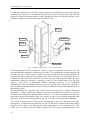
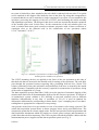
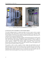
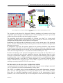
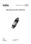
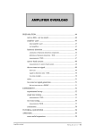
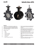
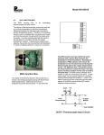
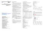
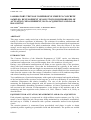
15th International Conference on Experimental Mechanics
PAPER REF: 3762
LABORATORY TESTS OF COMPRESSIVE CREEP IN CONCRETE
SAMPLES: DEVELOPMENT OF SOLUTIONS FOR PROBLEMS OF
ACTUATION, MEASUREMENT, DATA ACQUISITION AND LOAD
BALANCING
João Palma(*), Paulo Morais, Gustavo Coelho, A. Bettencourt Ribeiro
Laboratório Nacional de Engenharia Civil, Lisboa, Portugal
(*)
Email: [email protected]
ABSTRACT
This paper reports a study carried out to develop an automatic facility for compressive creep
testing of concrete specimens in laboratory. The solutions for actuation, measurement and
data acquisition were developed after the identification of the main metrological requirements
and operational constraints. The whole transduction chains, from the sensors to the data
storage, was be analysed in detail. In addition a software tool was developed as an aid to the
delicate process of force application and load balancing. The system has been tested and some
results are presented.
INTRODUCTION
The Concrete Division of the Materials Department of LNEC carries out laboratory
compressive creep tests of concrete specimens of 600150150 mm by submitting them to
constant axial compression, over periods ranging from a few months to several years.
During a test, deformation measurements are made on two opposite sides of the specimen,
along with load measurements. Given that the deformations are typically in the order of
several tens of microns in 400 mm length, its measurement needs highly sensitive measurement
devices that should also be easy to calibrate and require a detailed analysis of the metrological
chain from the sensors to the data storage. Furthermore, load as well as ambient temperature
and relative humidity may be measured with moderate cost instrumentation.
Test conditions are of particular importance with regard to the temporal and spatial uniformity
of the load applied to the specimen in the long run, as well as to uniformity of environmental
conditions (temperature and relative humidity). The ease of the devices placement for
measuring the deformation, alongside with the means for load application and balancing,
require substantially demanding operational conditions. All these requirements were taken
into account in the selection of instrumentation, in the design of the machines and in the
monitoring and data acquisition tools (Palma et al, 2010; Gustavo Coelho et al, 2010), as
described next.
EQUIPMENT FOR ACTUATION, MEASUREMENT AND DATA ACQUISITION
Each prismatic specimen is compressed in a high stiffness reaction structure (see Fig. 1) by
means of an oil filled flat jack, the pressure being maintained by an hydraulic accumulator;
the load (up to 15 MPa) is measured with a pressure transmitter inserted in the hydraulic
circuit.
The reaction structure is constructed from press-braked steel plates in order to obtain
optimized profiles regarding to permissible loads and deformations. The profiles are welded
ICEM15
1
Porto/Portugal, 22-27 July 2012
to each other forming a closed frame. The test specimen is installed inside the frame directly
contacting the frame on one end and the flat jack on the other end. Between the flat jack and
specimen is placed an interface plate to better distribute the load. The flat jack consists of two
welded steel plates spin formed into a half toroidal section.
Reaction
structure
Accumulator
Interface plate
with the specimen
Pressure
transmitter
Flat jack
Spacer
Valve block
Filling block
Hydraulic piping
Fig. 1 - Schematic representation of a creep test system
The load application system consists of a block of valves, a hydraulic accumulator, the flat
jack and hydraulic piping and connecting accessories. The accumulator contains nitrogen and
oil under pressure. It has an initial volume of oil that can absorb the expected deformation of
the specimen and to make up for any small leaks of oil or nitrogen. The valve block allows to
temporarily isolate the flat jack from the rest of the circuit in order to perform hydraulic joint
maintenance, adjust the pressure of nitrogen or add oil. The toroidal form of the flat jack
allows a wide range of deformation without significant variation of its mechanical
characteristics. The relationship between the pressure applied inside and the force applied to
the specimen remain substantially constant until the deformation equals the initial diameter of
the toroidal section.
The deformations are measured with 75 mV/V/mm sensitivity linear variable differential
transformer (LVDT) transducers equipped with special mechanical interfaces to provide
protection and fixing points 400 mm apart; a stroke of ±2.5 mm, intentionally exceeding the
maximum expected deformation range, was chosen in order to cope with the manufacturing
tolerances of the specimen fixing points as well as to provide some clearance for handling.
The LVDT mounting device is represented schematically in Fig. 2(a). The device is mainly
composed by a support and an extension rod. The LVDT body is inserted inside the support
and fixed with a lock screw allowing for minor adjustments of the mechanical zero. The
LVDT core is attached to one end of the extension rod. The relative movement between the
2
15th International Conference on Experimental Mechanics
two parts is limited by a plate attached to the rod which is endowed with two slots. Two guide
screws attached to the support slide inside the slots in the plate. By using this arrangement it
is ensured that the set can be treated as a single component, even when it is not attached to the
specimen, preserving the integrity of the core of LVDT, and facilitating the initial assembly
and adjustment operations. The design of this device took into account the thermal expansion
of the metallic parts used. In this sense, for the construction of the rod stainless steel was
used, a solution that meets good corrosion resistance properties with a linear coefficient of
expansion close to the material used in the construction of test specimens (about
12×10-6 mm/mm/C° at 20 C°.
a
b
Fig. 2 (a) - Schematic representation of LVDT mounting device; (b) Detail view of
mounting device installation on specimens
The LVDT mounting devices are applied on the faces of the test specimen at the ends of
threaded rods that are inserted in the moulds used for casting of the specimens. The rods fully
pass through the specimen between opposing sides, protruding from the face 10 mm. The
relative positioning of the rods in distance and parallelism of the axes is ensured by the mould
within tolerances compatible with the accuracy required for construction of specimens, being
of the order of magnitude of 0.5 mm.
The data acquisition system (DataTaker, 2002) serves the purpose of automatic logging of the
measurement data from all instrumentation deployed in the concrete specimens. It consists of
an autonomous system (without a PC) allowing to start and conclude tests in different
machines independently at any time. A resolution of 130 µV is used in channels for
deformation measurement, corresponding to better than 0.1 µm; a sampling rate of less than 1
reading/hour is appropriate for compressive creep testing.
Any pressure losses have to be prevented or in case of occurrence to be timely corrected. The
actual data acquisition system allows to detect pressure losses and to send SMS alerts. The
compression system has no electric supply needs. An UPS was provided for the measurement and
data acquisition instruments which are sensitive to electric power outages and fluctuations; it
yields more than one hour autonomy. The UPS was placed inside the metallic cabinet with the
instrumentation power supplies and the data acquisition system (see Fig. 3).
ICEM15
3
Porto/Portugal, 22-27 July 2012
a
b
Fig.4 (a) Test machines with specimens and instrumentation; (b) The metallic cabinet with
the data acquisition system, the UPS and the power supplies..
LOAD BALANCING AND DIRECT STATE MONITORING
The initial loading operation is a delicate procedure and must comply with the required
specifications (LNEC Specification E399-1993). When a target specimen is initially loaded,
the deformation measurements in two opposite sides may not differ by more than 25% of the
average. Failure to do so the specimen must be unloaded and repositioning of the specimen is
required before repeating the loading operation.
In order to achieve appropriate balancing conditions to the target specimen, the operator needs
instant information of the pressure being applied as well as the deformations in two opposite
sides of the specimen. Thus, aiming to expedite the loading operating, a software module was
written to provide a Human-Machine Interface (HMI) to the autonomous data acquisition
system. Depicted in figure 4, the software module DataPicker easily accesses data
measurements without interfering with the actual data acquisition system and logging process
from any other test machines already in operation.
The operator is able to select a specific concrete sample and automatically query the
acquisition system for load and deformations values for that particular concrete specimen.
Both deformations and load values are acquired and converted according to their unique
parameters. These parameters are stored in a file that holds the conversion factor for each
instrumentation previously calibrated in order to accurately convert the acquired values (in
milivolts) to their measured physical value (respectively, in microns and bar).
4
15th International Conference on Experimental Mechanics
Cross-sections
deformations
values
Zero adjust
Applied
Load Value
Concrete
specimen
selector
Actual values
Acquisition
rate options
Fig 4 Compressive Creep Test HMI illustrating DataPicker software detail during a test set
up phase.
The program was developed for Microsoft Windows platforms and connects to the Data
Acquisition System through a serial RS232 port. It allows sampling rates up to 1 per second
without interfering with the actual data logging in progress.
The acquisition mode can be done manually (by clicking “get values”) or in auto mode
(selecting a sampling period). All acquired raw values (in volts) are stored in a log file and
catalogued by date for further analysis and/or record purpose.
Furthermore, the HMI provides a platform for access to the current state of all measuring
devices, therefore, allowing assessing, monitoring and record state conditions throughout the
laboratory test process.
In compressive creep tests, the pressure applied to the specimen should be kept constant
during all test period within 3% of the initial value in order to validate the compressive creep
results. Ambient monitoring is also crucial, since the requirements specifications defines tight
values for room temperature (20 +- 2ºC) and room relative humidity (50+- 5%).
Permanent monitoring of all specimens throughout their test periods not only allows us to
trace tests results but also provides immediate detection and alarming capacity at the
occurrence of undesirable conditions. Therefore, an unsupervised monitoring system capable
of sending alarm events via SMS messaging to system operators was implemented using a
GSM modem through a serial RS-323: when thresholds are overcome, dedicated alarm
routines embedded in the logging program send a SMS to report the event to the operators,
enabling to promptly implement corrective procedures.
METROLOGICAL CHAINS AND CALIBRATION NEEDS
A pressure transmitter rated for 250 bar (25 MPa), with 4–20 mA current analogue output and
± 0.5 % FS accuracy is used for load monitoring (Trafag, 2006).
The LVDT is a suitable choice for the measurement of the small deformations (presently
below 100 µm) with high stability in the long term (Pallas-Areny, 2001; Solartron, 2006).
Since there are specially demanding accuracy objectives in the measurement of these
quantities, a lot of effort should be put on each component of the entire metrological chains,
ICEM15
5
Porto/Portugal, 22-27 July 2012
from the physical sensor up to the production of digital measurements, namely: the mounting
device, the LVDT itself, the signal cabling and the data acquisition channel.
The concerns about the mounting devices were presented before. The LVDT has to be more
deeply analysed, in particular the consequences of its transduction principle: consisting of a
transformer working with alternating current (at 5 kHz), the output signal is obtained by peak
detection of the differential voltage, followed by smoothing; as a consequence, a residual
ripple content is expected and had to be corrected with further analogue filtering at the
entrance to the data acquisition system (in this application digital filtering would require
sampling rates higher than 10 kHz which was obviously out of scope).
Electromagnetic disturbances were mitigated by means of: (1) short length cabling (the data
acquisition cabinet is placed near the centre of the plant, which is distributed by two rooms);
(2) separation of signal circuits from power circuits; (3) careful grounding and (4) signal cable
screening. Good quality and stable power supplies of +10V/-10V were chosen; in addition
both supply voltages are also monitored by the data acquisition system in order to make
suitable corrections since the sensitivity of LVDTs is proportional to the excitation voltage.
Each LVDT carries an individual sensitivity value obtained by calibration in the factory,
under a given excitation and environmental conditions which are not always met in the
applications. For the present system an in situ calibration with a traceable precision
instrument was needed. It is highly recommended that an individual calibration is made for
each LVDT chain including the LVDT itself, the respective cabling and filtering, as well as
its exclusive channel in the data acquisition system.
CONCLUSIONS
The design of a creep test facility, namely the actuating machines and the instrumentation, the
selection and adaptation of sensors as well as of data acquisition equipment and software is a
complex task having multiple matters of concern, as described in this paper.
Special tools had to be provided in order to ease the balancing and set up operation as well as
for direct state monitoring without interfering with the automatic logging. Additional
alarming resources, to be triggered in the occurrence of undesired loading or ambient
conditions, were also considered.
The highly demanding measurement of deformations (in the order of a few tens of
micrometers) strongly recommend the individual calibration of each entire deformation
measurement chain, for the purpose of achieving the best measurement quality and should be
put in practice at short term. A calibration study should be pursued in the forthcoming
developments.
Experimental results obtained so far reveal the functionality of this lab facility as well as its
stability.
REFERENCES
Palma J, Morais P, Esteves Coelho G, Data Acquisition System for Creep Tests of Concrete
Samples Under Compression. Report no. 121/2010-CIC (in portuguese), LNEC, 2010.
Esteves Coelho G, Palma J, A monitoring program for Creep Test of Concrete Samples under
compression Datapicker (version 3.0.4). Report no. 232/2010-NSE (in portuguese), LNEC,
2010.
6
15th International Conference on Experimental Mechanics
Pallas-Areny R, Sensors and Signal Conditioning, 2nd edition, Wiley, 2001.
DataTaker Pty Ltd, DT50, DT500, DT600 Series dataTakers User’s Manual, Series 3, UM0076-A0, 1991-2002.
DataTaker, DT5/6xx User’s Manual (Series 3), 2002.
DataTaker, Powerful Data Logger and Flexible Data Acquisition and Data Logging Systems www.datataker.com.
SOLARTRON Metrology, Complete Catalog, C2006/01/E, 2006.
SOLARTRON Metrology, Analogue Electronics Basic Operation of the DC-DC Transducer,
Application Note 502355, Issue 2, s.d.
TRAFAG Sensors and Controls, Display Control Switch DCS – 8864, Datasheet 6.2.2.4,
2006.
LNEC Specifications – Concrete:
LNEC, 1993
ICEM15
measurements of creep in compression. E399-1993,
7