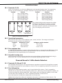
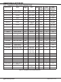
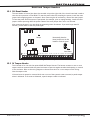
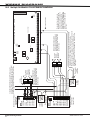
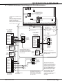
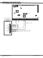
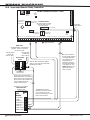
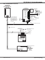
1
INSTALLATION GUIDE
XR200—242-ZONE
COMMAND PROCESSOR™ PANEL
MODEL XR200
COMMAND PROCESSOR
INSTALLATION GUIDE
FCC NOTICE
This equipment generates and uses radio frequency energy and, if not installed and used properly in strict accordance
with the manufacturer’s instructions, may cause interference with radio and television reception. It has been type tested
and found to comply with the limits for a Class A computing device in accordance with the specification in Subpart J
of Part 15 of FCC Rules, which are designed to provide reasonable protection against such interference in a residential
installation. If this equipment does cause interference to radio or television reception, which can be determined by
turning the equipment off and on, the installer is encouraged to try to correct the interference by one or more of the
following measures:
Reorient the receiving antenna
Relocate the computer with respect to the receiver
Move the computer away from the receiver
Plug the compute into a different outlet so that computer and receiver are on different branch circuits
If necessary, the installer should consult the dealer or an experienced radio/television technician for additional suggestions.
The installer may find the following booklet, prepared by the Federal Communications Commission, helpful:
“How to identify and Resolve Radio-TV Interference Problems.”
This booklet is available from the U.S. Government Printing Office, Washington D.C. 20402
Stock No. 004-000-00345-4
© 2003 Digital Monitoring Products, Inc.
Information furnished by DMP is believed to be accurate and reliable.
This information is subject to change without notice.
TABLE OF CONTENTS
Revisions to This Document
Product Specifications
1.1
1.2
1.3
1.4
1.5
1.6
1.7
Power Supply .........................................1
Communication.......................................1
Panel Zones............................................1
Keypad Data Bus ....................................1
LX-Bus™ ................................................1
Outputs..................................................1
Enclosure Specifications ..........................1
Panel Features
2.1
2.2
2.3
2.4
2.5
2.6
2.7
2.8
Description .............................................2
Expansion Zones.....................................2
Relay Output Expansion ..........................2
Partitions and Areas ................................3
Central Station Communication ................3
Before you Begin ....................................3
About this Guide .....................................3
How to Use This Guide ............................3
System Components
3.1
3.2
3.3
3.4
Description .............................................4
Wiring Diagram.......................................4
Lightning Protection ................................5
Accessory Devices...................................5
Installation
4.1
4.2
4.3
Mounting the Enclosure...........................6
Mounting Keypads and
Zone Expansion Modules .........................7
Connecting Serial Devices........................7
Primary Power Supply
5.1
5.2
AC Terminals 1 and 2 ..............................7
Transformer Types ..................................7
Secondary Power Supply
6.1
6.2
6.3
6.4
6.5
6.6
6.7
6.8
Battery Terminals 3 and 4........................8
Earth Ground..........................................8
Battery Only Restart................................8
Replacement Period ................................8
Discharge/Recharge ................................8
Battery Supervision .................................8
Battery Cutoff.........................................8
XR200 Power Requirements.....................8
Bell Output
7.1
Terminals 5 and 6 .................................10
Keypad Data Bus
8.1
8.2
8.3
8.4
8.5
XR200 Installation Guide
Description ...........................................10
Terminal 7 - RED ..................................10
Terminal 8 - YELLOW ............................10
Terminal 9 - GREEN ..............................10
Terminal 10 - BLACK .............................10
Digital Monitoring Products
i
TABLE OF CONTENTS
Smoke and Glassbreak Detector Output
9.1
9.2
Terminals 11 and 12..............................10
Current Rating ......................................10
Protection Zones
10.1
10.2
10.3
10.4
Terminals 13–24 ...................................11
Operational parameters .........................11
Zone response time ..............................11
Keyswitch arming zone..........................11
Powered Zones for 2-Wire Smoke Detectors
11.1
11.2
11.2
Terminals 25–26 and 27–28...................11
Zone Information ..................................11
Compatible 2-Wire
Smoke Detector Chart ...........................12
Dry Contact Relay Outputs
12.1
12.2
12.3
Description ...........................................13
Contact Rating......................................13
Output Harness Wiring ..........................13
12 VDC Voltage Outputs 3 to 10
13.1
13.2
Description ...........................................13
Output Harness Wiring ..........................13
Telephone RJ Connector
14.1
14.2
14.3
14.4
14.5
Description ...........................................14
FCC registration ....................................14
Notification...........................................14
Ground Start ........................................14
Answering Machine Bypass ....................14
Reset and Tamper Headers
15.1
15.2
J16 Reset Header .................................15
J4 Tamper Header ................................15
Universal UL And NFPA Fire Alarm Specifications
16.1
16.2
16.3
16.4
16.5
16.6
16.7
16.8
16.9
16.10
16.11
16.12
16.13
Introduction .........................................16
Wiring..................................................16
Transformer..........................................16
End-of-Line Resistor ..............................16
System Trouble Display .........................16
Fire Display ..........................................16
Police Station Phone Number .................16
System Maintenance .............................16
Audible Alarm .......................................16
Fire Zone Programming .........................16
Style D Zones .......................................16
Video Option ........................................16
UL Listed Receivers ...............................16
UL 985 NFPA 72 (Chapter 2) Specifications
17.1
Digital Monitoring Products
ii
Bell Output Definition ............................17
XR200 Installation Guide
TABLE OF CONTENTS
UL 864 NFPA 72 (Chapter 9) Specifications
18.1
18.2
18.3
18.4
18.5
18.6
18.7
18.8
18.9
18.10
Zone Restoral Reports ...........................17
Power Fail Delay ...................................17
Sprinkler Supervisory ............................17
DACT Systems ......................................17
Type 2 and Type 3
Central Station Service ..........................17
Type 1 Central Station Service ...............17
Local Protective Signaling Systems .........18
Proprietary Protective
Signaling Systems .................................18
Remote Station Protective
Signaling Systems .................................18
Fire Protective Signaling
Systems with an iCOM™........................18
California State Fire Marshal Specifications
19.1
Bell Output Definition ............................18
Wiring Diagrams
20.1
20.2
20.3
20.4
20.5
20.6
20.7
Notification Circuit Module Installation ....19
Multiple Notification Circuit
Module Installation ...............................20
Multiple Notification Circuit
Modules for Zoned Annunciation ............21
Dual Style D Zone Module Installation ....22
Remote Station Reversing
Relay Connection ..................................23
Supervised Remote Relay Connection .....24
LX-Bus Module Connection ....................25
Operating Instructions
XR200 Installation Guide
Digital Monitoring Products
iii
REVISIONS
Revisions to This Document
This section explains the changes that were made to this document during this revision. This section lists the date
the change was made, the section number and section heading, and a quick summary of the change.
Date
Section Number and Heading
Quick Explanation of Changes
12/06 3.2 Wiring Diagram
13.2 Output Harness Wiring
16 Universal UL Burglary Specifications
17 UL 1023 Specifications
18 UL 1610 and 1076 Specifications
19 UL 1635 Specifications
20 UL 365 and 609 Specifications
Removed UL Burglary and Access Control text and information.
Removed UL Burglary and Access Control text and information.
Removed entire section. UL listing expired.
Removed entire section. UL listing expired.
Removed entire section. UL listing expired.
Removed entire section. UL listing expired.
Removed entire section. UL listing expired.
Note: Subsequent section numbers revised.
20.8 Rothenbuhler Install
Diagram removed.
20.9 Cell Backup for Derived Chanel Burg Diagram removed.
Note: Subsequent section numbers revised.
3/04
3.2 Wiring Diagram
Section 6.8
25.7 Cellular Backup Installation
for Derived Channel Burglary
Added UL required text and information.
Added keypad models 690F, 790F, and 693.
Added/revised current draw information.
Revised drawing and added STU connection text.
6/03
FCC Statement
Entire Document
6.8 Standby Battery Calculations
10.3 Zone Response Time
11.1 Terminals 25-26 and 27-28
Adjusted to properly reflect Class A.
Added SCS-1R references to the appropriate places.
Current Draw on some products adjusted.
Changed from 160 milliseconds to 167.
EOL information clarified.
7/02
4.1 Mounting the Enclosure
1.7 Enclosure Specifications
11.1 Terminals 25-26 and 27-28
23.7 Local Protective Signaling Systems
Model 325 Transformer Bracket, Terminal Strip added to Figure 3.
Information added about 349, 350, 350A Enclosures.
Information added about Sensor Reset’s affect on Zones 9 and 10.
Information added requiring the 893 to be used in local commercial
fire installations
Section added with compliance information for the iCOM.
23.10 Fire Protective Signaling
Systems with an iCOM™
10/01 3.4 Accessory Devices
4.3 Connecting Serial Devices
6.8 XR200 Power Requirements
11.2 Compatible 2-Wire Smokes
Digital Monitoring Products
iv
New DMP products added to the table.
LX-Bus and keypad bus information added.
710F added to the Standby Battery Calculations chart.
Chart updated to include smoke detectors that are compatible with
the 725 zone expander and other 12 VDC smoke detectors.
XR200 Installation Guide
INTRODUCTION
Product Specifications
1.1
Power Supply
Transformer Input: 16.5 VAC 40 VA (Models 320 or 321)
Standby Battery: 12 VDC 7.7Ah (40 VA charges 2 batteries; 56 VA and 100 VA charges up to 4 batteries)
Auxiliary: 12 VDC output at 1 Amp
Bell Output: 12 VDC at 1.5 Amp
All circuits are inherent Power Limited except the red battery wire.
1.2
Communication
Built-in dialer communication to DMP Model SCS-1 and SCS-1R Receivers
Built-in multiplex communication to DMP Model SCS-1 Receivers
Built-in Contact ID communication to non-DMP receivers
Built-in Modem IIe communication to non-DMP receivers
Optional 893 or 893A Dual Phone Line Modules with phone line supervision
Optional Host communication through Ethernet data networks
Can operate as a local panel
1.3
Panel Zones
Eight 1k Ohm EOL burglary zones (zones 1 to 8)
Two 3.3k Ohm EOL Class B (Style A) powered zone with reset (zones 9 and 10)
1.4
Keypad Data Bus
You can connect up to eight of the following supervised keypads and expansion modules to the XR200 keypad
data bus: Alphanumeric keypads, four and single zone expansion modules, and single zone detectors.
1.5
LX-Bus™
You can connect the following devices to the LX-Bus™ provided by the DMP 462N, 462P, 462FM, 472, and 481
Interface Cards up to the maximum number of LX-Bus™ addresses. See Accessory Devices in section 3.4.
• Four and single zone expansion modules
• Relay output expansion modules
1.6
• Single zone detectors
• Graphic annunciator modules
Outputs
The XR200 provides two SPDT relay outputs which require the installation of two Model 305 relays, each
rated 1 Amp at 30 VDC resistive) power limited sources only. The XR200 also provides 8 auxiliary 12 VDC,
50mA resistive outputs. To use these outputs, you need one Model 430 Output Harness.
1.7
Enclosure Specifications
The XR200 is shipped in an enclosure with End-of-Line resistors, battery leads, User’s Guide, and
Programming Sheets.
Model 349 Enclosure (XR200M)
Model 350A Enclosure (XR200A)
Model 350 Enclosure (XR200L)
XR200 Installation Guide
Dimensions:
12.5” W x 11.5” H x 3.5” D - 8 lbs with panel
Color:
Black (61), Gray (63), or Red (81)
Construction: 20-gauge cold-rolled steel
Dimensions:
17.5” W x 13.5” H x 3.75” D (enclosure only)
Color:
Black (61), Gray (63), or Red (81)
Construction: Door: 16-gauge cold-rolled steel.
Back and Sides: 18-gauge cold-rolled steel
Dimensions:
17.5” W x 13.5” H x 3.5” D - 10 lbs with panel
Color:
Black (61), Gray (63), or Red (81)
Construction: 18-gauge cold-rolled steel
Digital Monitoring Products
1
INTRODUCTION
Panel Features
2.1
Description
The DMP XR200 Command Processor™ Panel is a versatile 12 VDC, combined burglary and fire communicator
panel with battery backup. The XR200 provides 8 on-board burglary zones and 2 on-board 12 VDC Class B
powered zones. The powered zones have a reset capability to provide for 2-wire smoke detectors, relays,
or other latching devices. The XR200 can communicate to one or two DMP SCS-1 Receivers using multiplex,
host, or digital dialer; one or two to DMP SCS-1R using host or digital dialer; or to non-DMP receivers using
the Contact ID and Modem IIe formats.
������������������������������
���������������������������
����������������������������
����
���������
�������
�
��
�
��
�
���
�
���
�
����
�
���
�
�
���
�
���
��
���
��
���
��
���
��
���
��
��
��
���
��
��
��
��
��
���
��
���������
���������
���������
��
���������
���������
���������
�����������
�����������
���������
���������
���������
������
������
������
���
���
���
������
������
���
���
����������������
�����������������
���������
������
��������
�����������
�����������
������
������
������
���
���
���
����������������
���������
������������
������
����������������
���������������������������������
�����������������������
Figure 1: Typical XR200 System Configuration
2.2
Expansion Zones
Up to 232 additional zones are available on the XR200 using the remote zone capability of DMP Security
Command keypads and zone expander modules. The panel’s keypad data bus supports up to eight supervised
device addresses with each address supporting up to four programmable expansion zones.
Up to 200 zones are available using the Model 460 Interface Adaptor, 462N, 462P, 462FM, 472, or 481
Interface Cards, and any combination of zone expansion modules and single zone LX-Bus™ detectors.
Note: Do not use shielded wire for LX-Bus or Keypad Bus circuits.
2.3
Relay Output Expansion
In addition to the 2 SPDT relays and 8 voltage outputs on the XR200, you can also connect up to 25 Model 716
Output Expansion modules to each LX-Bus. These modules can provide an additional 200 programmable SPDT
relays. The XR200 provides 50 Output Schedules you can use for programming the 716 to perform a variety of
annunciation and control functions. You can also assign the 716 outputs to any of the panel’s Output Options
such as Fire Alarm, Communication Fail, or Phone Trouble Outputs.
The LX-Bus™ also supports the Model 717 Graphic Annunciator Module. Each 717 module supplies 20
switched ground outputs that follow the state of their assigned zones.
Digital Monitoring Products
2
XR200 Installation Guide
INTRODUCTION
2.4
Partitions and Areas
The 20 reporting areas of the XR200 are divided into four separate partitions. Partition 1 provides up to eight
individual reporting areas while partitions 2, 3, and 4 each provide up to four individual reporting areas.
Keypads installed on the XR200 system are assigned to partitions allowing users to operate the functions of
those areas.
2.5
Central Station Communication
You can program the XR200 panel for one of many communication formats:
• Local annunciation only
• Reporting to one or two DMP SCS-1 Receivers using multiplex, host, or digital dialer
• Reporting to one or two DMP SCS-1R Receivers using host or digital dialer
The panel can also communicate to non-DMP receivers using the Contact ID or Modem IIe communication
formats. The XR200 connects at the premises to a standard RJ31X or RJ38X telephone jack. Use the DMP
893 or 893A Dual Phone Line Module when connecting the XR200 panel to two separate phone lines in fire or
burglary applications.
2.6
Before you Begin
Before installing the XR200, we recommend you read through the entire contents of this guide. Familiarize
yourself with the features of the panel and the key points to remember during the installation. Be sure to
read and understand all of the caution statements printed in bold italics.
2.7
About this Guide
The information in this guide is organized into five sections:
• The Table of Contents at the front lists the headings and subheadings used throughout each section of
the guide. To the right of each heading is the section number where the information can be found.
• The Introduction section gives you an overview of the various components that go into a XR200 system
and provides diagrams of typical system configurations.
• The Installation section begins with mounting instructions for the enclosure and continues on to detail
the operational characteristics of the XR200 panel.
• The Compliance section describes the various regulations the XR200 complies with, such as UL.
• The System Diagrams illustrate different ways to wire the XR200 to a variety of modules.
Caution notes
Throughout this guide you will see caution notes containing information you need to know when installing
the XR200 panel. These cautions are written with a bold, italicized introductory clause followed by a
detailed description of the caution. See the example shown below:
Always ground the panel before applying power to any devices: The XR200 must be properly grounded
before connecting any devices or applying power to the panel. Proper grounding protects against
Electrostatic Discharge (ESD) that can damage system components.
Whenever you see a caution note, make sure you completely read and understand its information. Failing
to follow the caution note can cause damage to the equipment or improper operation of one or more
components in the system.
2.8
How to Use This Guide
To locate information about the installation of the XR200, first go to the Table of Contents at the front of
this guide. Find the subject heading that best describes the information you need and turn to the section
number shown to the right of the heading.
The text that follows the heading has been written to provide as much information about the subject as
possible. If you cannot find the information you need under that heading, try scanning through a few of the
headings before and after and reading the text under those that sound similar.
XR200 Installation Guide
Digital Monitoring Products
3
INTRODUCTION
System Components
3.1
Description
The DMP XR200 system is made up of an alarm panel with a built-in communicator, an enclosure, battery,
one 16.5 VAC transformer, and a keypad. You can add up to eight supervised Security Command® keypads;
wireless, network communications, and expansion interface cards; zone and output expander modules; and
initiating and indicating circuit modules. You can also connect auxiliary devices to the panel’s output relays
to expand the basic system’s control capability. Combined current requirements of additional modules may
require an auxiliary power supply. Refer to section 6.8 in this guide when calculating power requirements.
3.2
Wiring Diagram
The XR200 system below shows some of the accessory modules you can connect for use in various
applications. A brief description of each module follows in section 3.4.
����������������������������������������������
��������������������������������������������
���������������������������������������������
��������������������������������������������������
���������������������������������������
��������������������������������
�
�
��������
���������
������������������������������
�����������������������������������
������������������������������
����������������������������������
�����������������������������
�����������������������������������
���������������������������������
��������������������
������
�����
����������������
����������������
�����������
�
�
�
�
����
��
��
��
��
��
��
��
��
��� ���
��� ���
��
��� ���
��� ���
��
��� ���
��� ���
�����
��
��
��
��� ��� ���� ����
�� ��
�� ��
�����
�
����
��
�����
�����
�������
�����������
�����
�������������
�����������
�������
����������
����������
������
�����
����������������
������������������
����������
����������������
����������������
�����������
�����������������
���������������
��������������
��������������
�������������
��������
����������������
����������������
����
������������������
��� ���
��� ���
� ��������������������
�
���������������
����
����
��������� ���������
��������������������������������
���������������������������������� ������������� ������������� ������
��������
���������������������
�����
������
�����
�����
������
���������
������
��������
���
����������������������������������������������������
����������������������������������������������
���
������
�����
��
�� ��� ��
������
��
������
�
������
�
�� ��� ��
������
�������������������������
�
���������������������������
�
���������������������������
���
�����
�
������
�
��������
����������
�����
�� ��� ��
������
�
����������������
�
����������������
�
�����
�
�
�����
�
�� ���� ��� ��� ��� ��� ��� ��� ��� �� ��� ��
����������������
��
����������������
��
�� ��
���������������
��������������
������
���������������
��������������
��
����
��������
�����������������������������
���������������������������������
����������������
�������������������
����
�������
���
���
���������
� ����������
��������
�����
��������
���
������
��������������
����������
�����������
��������������
�������
����������������������
���������������������������������
�����������������������������
���������������������������
���������������������������
�������������������������������������������
������������������������������������������
�������������������������������������
����������
�������
�������� �� �� ������������
�������
����������������������������������
����������������������������������
�������
�������������
���������� ����� ������
��������� ���� ����
��������� ���� ������
���������� ����� ������
��������� ���� ����
��������� ���� ������
���������������
��������� ������������
��������� ������������
��������� �����������
��������� ����������
��������� ������������
��������� ����������
��������� �����
���������� �����������
�������
�����
������������������������������������������
���������������������������������
��� ���
������
��
�������
���������������
���������������
�������������������
���������������
�������������
���������������
����������
���������������
����������
���������������
����������
���������������
�����������
��������������
�����������
���������������
���������������������
�������������������������������������������
���������������������������������������������������
��������������������������
�������������
�������������������������������������������������������������
�������������������������������������������������������������
�������������
�������������������
������������������������
������������������������
������������������������
����������������
���������
���������������
����������������
���������
���������������
����������������
���������
���������������
����������������
������������������������������
����������������������������������������������
��������������������������������������������
���������������������������������������
���������������������������������������
�������
��������������������������������������������������������������
������������������������������������������������������
����������������������������������������������������������
���������������������������������������������������������
����������������������������������������������������������
���������������������������������������������������������
����������
����������������
��������������������������������������������
������������������������������������������������
�����������������������
�����
�����
��������������
����������
������������
��������������������
�������������
������
���
������ ������ ������
��������������������
������������������
����������������
������
��������
��������������
���������
������������
��������������������
�������������
������ ������ ������
������
�������
����������������������������������������������������������������������
��������������������������������������������������������������������������
���������������������������������������������������������������������
������������������������������������������������������������������
����������������������������������������������������������������������
�����
���������
������������������������������������
���������
��������� ������������������������������
���
�������������������������������������
����������������������������������
������������������������������
����������������������������������
������
�������������������������������
����������������������������
����������������������������������
��������������������������������
������������������������������������������������
������������������������������������������������
����������������������������������
Figure 2: XR200 Wiring Diagram
Digital Monitoring Products
4
XR200 Installation Guide
INTRODUCTION
3.3
Lightning Protection
Metal Oxide Varistors and Transient Voltage Suppressors help protect against voltage surges on input and
output circuits of the XR200. Additional surge protection is available by installing the DMP 370 or 370RJ
Lightning Suppressors.
3.4
Accessory Devices
Interface Adaptor and Interface Cards
460 Interface Adaptor Card
462N Network Interface Card
462P Printer Interface Card
472 Inovonics 900 MHz Interface Card
481 Expansion Interface Card
Zone and Output Expansion Modules
710/710F Bus Splitter/Repeater
711/711E Single Point Zone Expansion Modules
712-8 Zone Expansion Modules
714, 714-8, 714-16 Zone Expansion Modules
715, 715-8, 715-16 Zone Expansion Modules
725 Zone Expansion Modules
716 Output Expansion Modules
717 Graphic Annunciator Module
Allows you to connect two or more expansion interface cards to the XR200 panel. The 461
is an expansion mother board that plugs into the J6 Interface Connector of the panel and is
required when using two or more Interface Cards. Use combinations of Interface Cards for
expanding zones, network interfacing, local printing, and connecting wireless devices. Requires
Model 349, 350, or 350A Enclosure.
Allows you to connect the XR200 to any compatible data network and use its communication
capability in place of standard dial out telephone lines. The 462N also provides an LX-Bus™ for
connecting zone and output expansion modules to the panel. The 462N is listed for Grade AA
Burglary communication and supplementary signaling.
Allows you to connect the XR200 to any compatible serial printer providing real-time event
recording to the user. The 462P also provides an LX-Bus™ for connecting zone and output
expansion modules.
Provides an interface between the Inovonics FA400-DMP Wireless Receiver and the XR200
panel. You can use any of the wireless equipment compatible with the FA400-DMP to construct
a strictly wireless or combined wireless/hardwire system. Wireless functionality is listed for
Household Fire and Burglary. The 472 also provides one LX-Bus™ for connecting zone and
output expansion modules.
Provides one LX-Bus for connecting up to 100 zone and output expansion modules.
Allows you to increase keypad or LX-Bus™ wiring distance to 2500 feet. Model 710F is for 24
VDC applications.
Provides one Class B zone for connecting burglary and non-powered fire devices.
Provides Class B zones for connecting burglary devices.
Provides Class B zones for connecting burglary and non-powered fire devices.
Provides 12 VDC Class B powered zones for connecting smoke detectors, glassbreak detectors,
and other 2- or 4-wire devices.
Provides 24 VDC Class B powered zones for connecting smoke detectors, glassbreak detectors,
and other 2- or 4-wire devices.
Provides four Form C relays (SPDT) and four switched grounds (open collector) for use in a
variety of remote annunciation and control applications.
Provides 20 zone following annunciator outputs (open collector) for use in a variety of remote
annunciation and control applications.
Indicating and Initiating Devices
865 Supervised Style Y or Z Notification Circuit
Module
866 Notification Circuit Module
867 Style W LX-Bus Notification Circuit Module
869 Dual Style D Initiating Module
Accessory Modules and Keypads
893A Dual Phone Line Module
ePAD Virtual Keypads
iCOM Internet Alarm Router
iCOM-E High-Security Internet Alarm Router
630F Remote Fire Command Center
Security Command LCD keypads
XR200 Installation Guide
Provides up to 1.5 Amps of supervised alarm current when using the bell output of the XR200
panel and up to 5 Amps at 12 or 24 VDC when using a listed auxiliary power supply. The 865
can supervise 2-wire Style Y or W circuits or X circuits for ground faults, opens, shorts, and
shorts with individual LED annunciation.
Provides up to 1.5 Amps of supervised alarm current using the bell output of the XR200 panel
and up to 5 Amps at 12 or 24 VDC when using a listed auxiliary power supply. The 866 can
supervise Style W circuits for opens and shorts.
Provides up to 1.5 Amps of supervised alarm current using the bell output of the XR200
panel and up to 5 Amps at 12 or 24 VDC when using a listed auxiliary power supply. The 867
connects to the LX-Bus™ of the XR200 panel and provides one 2-wire Style W notification circuit
for ground fault, open, and short conditions. Individual Bell Relay addresses Bell Ring styles.
Provides two Style D, 4-wire initiating zones for connecting waterflow switches and other nonpowered fire and burglary devices.
Allows you to supervise two standard phone lines connected to an XR200 panel. The 893A
module monitors the main and backup phone lines for a sustained drop in voltage and alerts
users when voltage drops below 3 VDC.
Allows users to control the security system from any computer in the world using the Internet.
Allows the panel to send signals through the Internet/Ethernet.
Allows the panel to send encrypted signals through the Internet/Ethernet.
Allows you control the panel from various remote locations. You may connect up to eight 630F
Remote Fire Command Centers to the keypad bus on terminals 7, 8, 9, and 10.
Allows you to control the panel from various remote locations. Connect up to eight supervised
Model 690, 790, 791, or 793 Security Command® keypads to the keypad bus (terminals 7, 8, 9,
and 10).
Digital Monitoring Products
5
INSTALLATION
Installation
4.1
Mounting the Enclosure
The metal enclosure for the XR200 must be mounted in a secure, dry place to protect the panel from
damage due to tampering or the elements. It is not necessary to remove the XR200 PC board when installing
the enclosure. Below are the mounting hole locations for the Model 350A Enclosure.
Note: The mounting holes are the same for the 350 Enclosure as those shown below for the 350A Enclosure.
������������������������
��
��� ���
������������������������������
��
��
������������������
���������
����������������
�������
������������
����������
�������
����������������
������������������
������������
���������������
���
��
��
��
��
�
�
�
��
�� ���� ��� ��� ��� ��� ��� ��� ��� �� ��� ��
�
�
�
�
�
�
��
��
��
��
��
��
�� ��� ��
�� ��� ��
��
��
��
��
��
��
�� ��� ��
��
��
��
��� ��� ���� ����
��
��
��
��
������������������������������������
������������������������
����������
������������
���������
������������
��������������
���������
�����
����������
������������
�������������
������������
����������
���������
���������
�����
����������������������������������������������
Figure 3: Model 350A Enclosure with Mounting Hole Locations
Digital Monitoring Products
6
XR200 Installation Guide
INSTALLATION
4.2
Mounting Keypads and Zone Expansion Modules
Security Command® keypads have removable covers that allow you to easily mount the keypad to a wall or
other flat surface using the screw holes on each corner of the base. Before mounting the base, connect the
keypad wire harness leads to the keypad cable from the panel and to any device wiring run to that location.
Then attach the harness to the pin connector on the PC board, mount the base, and install the keypad cover
making sure all of the keys extend through their respective holes.
For mounting keypads on solid walls, or for applications where conduit is required, use a DMP 775 or 776
keypad conduit backbox for 770 series keypads. To provide additional protection for the keypad against
unauthorized access, install the 777 Plastic Keypad Cover that provides a clear 1/8” thick polycarbonate
housing with locking mechanism. For the 790 series keypads, you can use the Model 695 1-1/2” deep or the
Model 696 1/2” deep backboxes.
DMP zone expansion modules are contained in molded plastic housings with removable covers. The housing
cover contains the module while the base provides you with two mounting holes for installing the unit to a
wall, switch plate, or other surface.
4.3
Connecting Serial Devices
Several factors determine the performance characteristics of the DMP LX-Bus™ and keypad bus: the length
of wire used, the number of devices connected, and the voltage at each device. When planning an LX-Bus™
and keypad bus installation, keep in mind the following four specifications:
1. You can install individual keypads on wire runs of up to 500 feet using 22-gauge wire or up to 1,000 feet
using 18-gauge wire. To increase the wire length or add additional devices, a power supply is required.
2. Maximum distance for any one circuit (length of wire) is 2,500 feet regardless of the gauge of wire.
This distance can be in the form of one long wire run or multiple branches with all wiring totaling no
more than 2,500 feet.
3. Maximum number of devices per 2,500 feet circuit is 40. (Note: Each panel allows a specific number
of supervised keypads. Additional keypads can be added in the unsupervised mode. Refer to the
panel’s installation guide for the specific number of supervised keypads that are allowed.)
4. Maximum voltage drop between the panel (or auxiliary power supply) and any device is 2.0 VDC. If the
voltage at any device is less than the required level, an auxiliary power supply should be added at the
end of the circuit.
Refer to the 710 Installation Sheet (LT-0310) for more information. Also see the LX-Bus/Keypad Bus Wiring
Application Note (LT-2031) for additional information.
Expansion Interface Cards (Models 462N, 462P, 462FM, 472, 481, and 482)
The LX-Bus provided on these cards requires only a 4-wire cable between the card and any devices
connected to the bus. You can connect devices (zone or output expansion modules) together on the same
cable or provide separate runs back to the cards. Up to 100 zones or relays are available on each LX-Bus.
Note: Do not use shielded wire when running an LX-Bus or keypad bus. Do not connect the 4 wires from the
Interface Card harness to the panel terminals.
Primary Power Supply
5.1
AC Terminals 1 and 2
Connect the transformer wires to terminals 1 and 2 on the panel. Use no more than 70 ft. of 16 gauge or 40
ft. of 18 gauge wire between the transformer and the XR200.
Always ground the panel before applying power to any devices: The XR200 must be properly
grounded before connecting any devices or applying power to the panel. Proper grounding protects
against Electrostatic Discharge (ESD) that can damage system components. See Earth ground section 6.2.
5.2
Transformer Types
The standard transformer for the XR200 is the Model 321 (16.5 VAC 40 VA). Refer to the XR200 Wiring
Diagram (LT-0204) on the panel enclosure door for a list of optional transformers that can be used with the
panel. The Model 320 wire-in transformer is available when required by the AHJ.
The transformer must be connected to an unswitched 120 VAC 60 Hz electrical outlet with at least 350mA of
available current. Never share the transformer output with any other equipment.
XR200 Installation Guide
Digital Monitoring Products
7
INSTALLATION
Secondary Power Supply
6.1
Battery Terminals 3 and 4
Connect the black battery lead to the negative terminal of the battery. The negative terminal connects
to the enclosure ground internally through the XR200 circuit board. Connect the red battery lead to the
positive terminal of the battery. Observe polarity when connecting the battery.
You can add a second battery in parallel using the DMP Model 318 Dual Battery Harness.
Use sealed lead-acid batteries only: Use the DMP Model 367, 12 VDC 7.0 Ah sealed lead-acid
rechargeable battery. Batteries supplied by DMP or manufactured by Eagle Picher or Yuasa have been
tested to ensure proper charging with DMP products.
GEL CELL BATTERIES CANNOT BE USED WITH THE XR200 PANEL.
6.2
Earth Ground
To provide proper transient suppression, terminal 4 of the XR200 panel must be connected to earth ground
using 14 gauge or larger wire . DMP recommends connecting to a cold water pipe or ground rod only. Do not
connect to an electrical ground or conduit, sprinkler or gas pipes, or to a telephone company ground.
6.3
Battery Only Restart
When powering up the XR200 panel without AC power, short across the CR7 leads to pull in the battery cutoff
relay. The leads need a momentary short only. Once the relay has pulled in, the battery voltage holds it in
that condition. If the XR200 panel is powered up with an AC transformer, the battery cutoff relay is pulled in
automatically.
6.4
Replacement Period
DMP recommends the battery be replaced every 3 to 5 years under normal use.
6.5
Discharge/Recharge
The XR200 battery charging circuit float charges at 13.9 VDC at a maximum current of 1.2 Amps using a 40 VA
transformer. The total current available is reduced by the combined auxiliary current draw from terminals 5,
6, and 24. The various battery voltage level conditions are listed below:
Battery Trouble:
Battery Cutoff:
Battery Restored:
6.6
Below 11.9 VDC
Below 10.2 VDC
Below 12.6 VDC
Battery Supervision
The XR200 tests the battery when AC power is present. The test is done every 3 minutes and lasts for 5
seconds. During the test, the panel places a load on the battery; if the battery’s voltage falls below 11.9
VDC a low battery is detected. If AC power is not present, a low battery is detected any time the battery
voltage falls below 11.9 VDC.
If a low battery is detected with AC power present, the test is repeated every 2 minutes until the battery
charges above 12.6 VDC; the battery has restored voltage. If a weak battery is replaced with a fully charged
battery, the restored battery will not be detected until the next 2 minute test is done.
6.7
Battery Cutoff
The panel disconnects the battery any time the voltage of the battery drops below 10.2 VDC. This prevents
deep discharge damage to the battery.
6.8
XR200 Power Requirements
During AC power failure, the XR200 panel and all auxiliary devices connected to the XR200 draw their
power from the battery. All devices must be taken into consideration when calculating the battery standby
capacity. On the following page is a list of the power requirements of the XR200 panel. Add the additional
current draw of Security Command® keypads, zone expansion modules, smoke detector output, and any
other auxiliary devices used in the system for the total current required. The total is then multiplied by the
number of standby hours required to arrive at the total ampere-hours required.
Digital Monitoring Products
8
XR200 Installation Guide
INSTALLATION
Standby Battery Power Calculations
XR200 Control Panel
Relay Outputs 1-2 (ON)
Voltage Outputs 3-10 (ON)
Active Zones 1-8
Active Zones 9-10
2-Wire Smoke Detectors
Panel Bell Output
893/893A Dual Phone Line Module
460 Interface Adaptor Card
462N Network Interface Card
462P Printer Interface Card
472 Inovonics 900MHz Interface Card
481 Expansion Interface Card
485 Enhanced Access Control Expansion Card
865 Style y or Z Notification Module
866 Style W Notification Module
867 LX-Bus Style W Notification Module
630F Remote Fire Command Center
690/690F Security Command Keypad
Annunciator (ON)
790/790F Security Command Keypad
Active Zones (EOL Installed)
Annunciator (ON)
791 Easy Entry Keypad
Active Zones (EOL Installed)
Annunciator (ON)
693/793 Easy Entry Keypad
Active Zones (EOL Installed)
Annunciator (ON)
770, 771 Security Command Keypads
Active Zones (EOL Installed)
Annunciator (ON)
733 Wiegand Interface Module
Active Zones (EOL Installed)
Annunciator (ON)
736P POPIT Interface Module
Radionics Popex, POPITs, OctoPOPITs
738A Ademco Wireless Interface Module
710 Bus Splitter/Repeater Module
710F Fire Bus Splitter/Repeater Module
711, 771E, 714 Zone Expansion Modules
Active Zones (EOL Installed)
712-8 Zone Expansion Module
Active Zones (EOL Installed)
714-8, 714-16 Zone Expansion Module
Active Zones (EOL Installed)
715 Zone Expansion Module
Active Zones (EOL Installed)
2-Wire Smokes
715-8, 715-16 Zone Expansion Modules
Active Zones (EOL Installed)
2-Wire Smokes
716 Output Expansion Module
Active Form C Relays
717 Graphic Annunciator Module
Annunciator Outputs
521LX, 521LXT, SLRLX Smoke Detectors
iCOM, iCOM-E Internet Alarm Routers
Aux. Powered Devices on Terminals 7 and 11
Other than Keypads and LX-Bus Modules
Qty
Qty
Qty
Qty
Qty
Qty
Standby Current
______x
80mA ______mA
______x
30mA ______
______x
5mA ______
______x
1.6mA ______
______x
4mA ______
______x
0.1mA ______
Qty ______x
Qty
Qty
Qty
Qty
______x
______x
______x
______x
Qty
Qty
Qty
Qty
Qty
______x
______x
______x
______x
______x
30mA
7mA
50mA
50mA
85mA
15mA
45mA
26mA
45mA
30mA
60mA
77mA
______
______
______
______
______
______
______
______
______
______
______
______
Qty
Qty
Qty
Qty
Qty
Qty
Qty
Qty
Qty
Qty
Qty
Qty
Qty
Qty
Qty
Qty ______x
77mA ______
1.6mA ______
Qty
Qty
Qty ______x
100mA ______
1.6mA ______
Qty
Qty
Qty ______x
92mA ______
1.6mA ______
Qty
Qty
Qty ______x
Qty ______x
100mA ______
1.6mA ______
Qty
Qty
Qty ______x
Qty ______x
30mA ______
1.6mA ______
Qty
Qty
Qty
Qty
Qty
Qty
Qty
Qty
Qty
Qty
Qty
Qty
Qty
Qty
Qty
25mA
___mA
75mA
30mA
40mA
7mA
1.6mA
17mA
1.6mA
20mA
1.6mA
7mA
4mA
.1mA
20mA
4mA
.1mA
7mA
Qty
Qty
Qty
Qty
Qty
Qty
Qty
Qty
Qty
Qty
Qty
Qty
Qty
Qty
Qty
Qty
Qty
Qty
______x
______x
______x
______x
______x
______x
______x
______x
______x
______x
______x
______x
______x
______x
______x
Qty ______x
______
______
______
______
______
______
______
______
______
______
______
______
______
______
______
______
______
______
Qty ______x
10mA ______
Qty ______x
8.8mA ______
______mA
Qty
Qty
Qty
Qty
Qty
Alarm Current
80mA ______mA
______x
30mA ______
______x
5mA ______
______x
*2mA ______
______x
30mA ______
______x
0.1mA ______
1500mA ______mA
______x
50mA ______
7mA ______
______x
50mA ______
______x
50mA ______
______x
85mA ______
______x
15mA ______
45mA ______
______x
85mA ______
______x
75mA ______
______x
85mA ______
______x
92mA ______
______x
84mA ______
20mA ______
______x
84mA ______
______x
*2mA ______
20mA ______
______x
100mA ______
______x
*2mA ______
20mA ______
______x
120mA ______
______x
*2mA ______
20mA ______
______x
100mA ______
______x
*2mA ______
20mA ______
______x
30mA ______
______x
*2mA ______
______x
20mA ______
______x
25mA ______
______x
___mA ______
______x
75mA ______
______x
30mA ______
______x
40mA ______
______x
7mA ______
______x
*2mA ______
______x
17mA ______
______x
*2mA ______
______x
20mA ______
______x
*2mA ______
______x
7mA ______
______x
*30mA ______
______x
.1mA ______
______x
20mA ______
*30mA ______
.1mA ______
______x
7mA ______
______x
28mA ______
______x
10mA ______
______x
1mA ______
______x
*28mA ______
78.1mA ______
______mA
*Based on 10% of active zones in alarm
Total Standby ______mA
Total Alarm ______mA
Total Standby______mA x number of Standby Hours needed ______ =
________mA-hours
Total Alarm ______mA + ________mA-hours
Cannot exceed 7.7Ah with one Model 367 Battery
Total ________mA-hours
Cannot exceed 15.4Ah with two Model 367 Batteries
Cannot Exceed 23.1Ah with three Model 367 Batteries
X .0001
Cannot exceed 30.8Ah with four Model 367 Batteries
= ________Amp-hrs
Required
XR200 Installation Guide
Digital Monitoring Products
9
INSTALLATION
Bell Output
7.1
Terminals 5 and 6
Terminal 5 supplies positive 12 VDC to power alarm bells or horns. The output is rated for a maximum output
of 1.5 Amps. This output can be steady or pulsed depending upon the Bell Action specified in Output Options.
Terminal 6 is the ground reference for the bell circuit.
Keypad Data Bus
8.1
Description
Terminals 7, 8, 9, and 10 of the XR200 panel are for the keypad data bus. You can connect up to eight
supervised keypads and an unlimited number of unsupervised keypads to the XR200. In addition to Security
Command keypads, you can also connect any combination of zone expansion modules, 5845LX Glassbreak
detectors and 6155LX PIRs to the data bus. Refer to the device’s Installation sheet for the maximum number
of devices on one keypad or LX-Bus™.
Note: Do not use shielded wire for LX-Bus/Keypad Bus circuits.
8.2
Terminal 7 - RED
This terminal supplies positive 12 VDC to power Security Command® keypads and zone expansion modules.
Terminal 7 also supplies power for any auxiliary device. The ground reference for terminal 7 is terminal 10
with the maximum output rated at 1 Amp.
The output current is shared with the smoke detector output on terminal 11 and Zones 9 and 10. All devices
totalled together must not exceed the panel’s maximum current rating of 1 Amp.
8.3
Terminal 8 - YELLOW
Terminal 8 receives data from keypads and zone expansion modules. It cannot be used for any other
purpose.
8.4
Terminal 9 - GREEN
Terminal 9 transmits data to keypads and zone expansion modules. It cannot be used for any other purpose.
8.5
Terminal 10 - BLACK
Terminal 10 is the ground reference for Security Command keypads, zone expansion modules, and any
auxiliary devices being powered by terminal 7.
Smoke and Glassbreak Detector Output
9.1
Terminals 11 and 12
Terminal 11 supplies positive 12 VDC to power 4-wire smoke detectors and other powered devices. This
output can be turned off by the user for 5 seconds using the Sensor Reset User Menu option to allow latched
devices to reset. Terminal 12 is the ground reference for terminal 11.
9.2
Current Rating
The Output current from terminal 11 is shared with terminals 7, 26, and 28. The total current draw of all
devices powered from the panel must be included with terminal 11 calculations and must not exceed the
maximum output rating of 1 Amp.
Digital Monitoring Products
10
XR200 Installation Guide
INSTALLATION
Protection Zones
10.1 Terminals 13–24
Zones 1 to 8 (terminals 13 to 24) on the XR200 panel are all grounded burglary zones. For programming
purposes, the zone numbers are 1 through 8. Terminals 13 to 24 provide connection as listed below.
Terminal
13
14
15
16
17
18
Function
Zone 1 voltage sensing
Ground for Zones 1 & 2
Zone 2 voltage sensing
Zone 3 voltage sensing
Ground for Zones 3 & 4
Zone 4 voltage sensing
Terminal
19
20
21
22
23
24
Function
Zone 5 voltage sensing
Ground for Zones 5 & 6
Zone 6 voltage sensing
Zone 7 voltage sensing
Ground for Zones 7 & 8
Zone 8 voltage sensing
The voltage sensing terminal measures the voltage
through a 1k Ohm End-of-Line resistor to ground.
Dry contact sensing devices can be used in series
(normally-closed) or in parallel (normally-open) with
any of the burglary protection zones.
1K Ohm
Normally Open
1K Ohm
Normally
Closed
1K Ohm
Combination Normally Open
and Normally Closed
Figure 4: Protection Zone Wiring
10.2 Operational parameters
Each protection zone detects three conditions: open, normal, and short. The voltage and resistance
parameters for each condition are listed below:
Condition
Open
Normal
Short
Resistance on zone
over 1300 ohms
600 to 1300 ohms
under 600 ohms
Voltage on positive terminal
over 2.0 VDC
1.2 to 2.0 VDC
under 1.2 VDC
10.3 Zone response time
A condition must be present on a zone for 500 milliseconds before it is detected by the XR200 panel. Ensure
detection devices used on the protection zones are rated for use with this delay. The zones can also be
programmed for a fast response delay of 167 milliseconds.
10.4 Keyswitch arming zone
Using a keyswitch on an Arming type zone allows you to arm and disarm selected areas without having to
enter a user code. For more information refer to the XR200 Programming Guide, LT-0196.
Powered Zones for 2-Wire Smoke Detectors
11.1 Terminals 25–26 and 27–28
Two resettable Class B (Style A) 2-wire powered zones are provided on terminals 25 through 28 on the panel.
For programming purposes the zone numbers are 9 and 10. The UL compatibility identifier for the zones is A.
11.2 Zone Information
When using 725 Zone Expansion modules, use UL Listed 6.8k Ohm EOL resistors. The UL compatibility
identifier for the zones using 725 Zone expansion modules is B. When using 715 Zone Expansion modules, use
UL Listed 3.3k Ohm EOL resistors (Model 309). When using all other zone expansion modules, use UL Listed
1.0k Ohm EOL resistors (Model 310). The UL compatibility identifier for the zones is A.
Do not mix detectors from different manufacturers on the same zone.
Caution: Performing a Sensor Reset will momentarily drop power to the devices on Zones 9 and 10. The
panel will view these zones 10 as “Open” while the power is dropped.
XR200 Installation Guide
Digital Monitoring Products
11
INSTALLATION
11.2 Compatible 2-Wire Smoke Detector Chart
Manufacturer
Model
Detector
ID
Base
Detection Systems
DS230, DS230F
B/A
MB2W, MB2WL
A
8.5-33
10
725
Detection Systems
DS250, DS250TH
B
MB2W, MB2WL
A
8.5-33
10/12
715, 715-8,
715-16, 725
Detection Systems
DS250HD
B
MB2W, MB2WL
A
8.5-33
10
715, 715-8,
715-16
Detection Systems
DS260
B/A
MB2W, MB2WL
A
8.5-33
17
725
Detection Systems
DS282, DS282TH
B
8.5-33
10/12
715, 715-8,
715-16, 725
DMP/Hochiki
SLK-835
HD-5
HSB-200, HSB200N
HB55
8-35
7
715, 715-8,
715-16
DMP/Hochiki
SLR-835
HD-3
NS6-100
HB55
8-35
7/14
715, 715-8,
715-16, 725
DMP/Hochiki
SLR-835B
HD-6
8-35
7/14
715, 715-8,
715-16, 725
Hochiki
SLR-835B-2
HD-6
8-35
14
725
Hochiki
SLR-24, SLR-24H
HD-3
NS4-220
HB-3
15-33
15
725
Hochiki
SIJ-24, DCD-190, DCD135
HD-3
NS4-220
HB-3
15-33
15
725
Hochiki
SLR-24, SLR-24H
HD-3
NS6-220
HB-3
15-33
15
725
Hochiki
SIJ-24
HD-3
NS6-220
HB-3
15-33
20
725
Hochiki
DCD-190, DCD-135
HD-3
NS6-220
HB-3
15-33
16
725
Sentrol/ESL
429AT, 521B, 521BXT
S09A
6.5-20
12
715, 715-8,
715-16
Sentrol/ESL
429C, 429CT, 521B/BXT
S10A
8.5-33
12
725
Sentrol/ESL
429CRT, 429CST,
429CSST, 521CRXT
S11A
8.5-33
12
725
Sentrol/ESL
711U, 712U, 713-5U,
713-6U, 721U, 721UT
S10A
701E, 70-1U,
702E, 702U
S00
8.5-33
12
725
Sentrol/ESL
731U, 723U
S11A
701E, 701U,
702E, 702U,
702RE, 702RU
S00
8.5-33
12
725
System Sensor
1100, 1400
STD
8.5-33
10
715
System Sensor
1151, 2151
STD
B110PL, B401
8.5-33
10/10
715, 725
System Sensor
1451, 2451TH
STD
B401, B401B
8.5-33
10
715
System Sensor
1451DH
STD
DH400
8.5-33
10
715
System Sensor
2100, 2100T
STD
8.5-33
10
715
System Sensor
2100S, 2100TS
A
8.5-35
12
725
System Sensor
2400, 2400AT, 2400AIT,
2400TH
STD
8.5-33
10
715
System Sensor
2451
STD
8.5-35
10
715
System Sensor
DH100P
A
8.5-35
10
725
B401, B401B,
DH400
Base
DC
# of
ID
Voltage Detectors
Range (12V/24V)
Zone
Expansion
Modules
Figure 5: Compatible 2-Wire Smoke Detectors
Digital Monitoring Products
12
XR200 Installation Guide
INSTALLATION
Dry Contact Relay Outputs
12.1 Description
The XR200 panel provides two auxiliary SPDT relays when equipped with two DMP Model 305 relays in sockets
K6 (Output 1) and K7 (Output 2) and a Model 430 Output Harness. Each relay provides one single pole,
double throw (SPDT) set of contacts that can be operated by any of the functions listed below:
1) Activation by zone condition
Steady
Pulsing
Momentary
Follow
2) Activation by 24-hour 7-day schedule
One on and one off time a day for each relay
3) Manual activation from the Security Command keypad menu
4) Communication failure
5) Armed area annunciation
6) Fire Alarm or Fire Trouble
7) Other system conditions. See the XR200 Programming Guide.
12.2 Contact Rating
The Model 305 relay contacts are rated for 1 Amp at 30 VDC resistive. You can connect auxiliary power to the
common terminal of Relay Output 1 by installing the gray harness wire to terminal 7.
12.3 Output Harness Wiring
The relay contacts are accessible by installing the DMP 430 Output Harness on the 15-pin header labeled J2.
The contact locations on the wire harness are shown below:
Output
Output
Output
Output
Output
Output
Contact
1 normally
1 common
1 normally
2 normally
2 common
2 normally
closed
open
closed
open
Color
Violet
Gray
Orange
Violet
Gray
Orange
The relay contacts must be connected to devices located within the same room as the XR200 panel.
12 VDC Voltage Outputs 3 to 10
13.1 Description
The XR200 also provides eight 12 VDC, 50mA resistive voltage outputs on J2 to power external relays or other
devices. The voltage outputs are operated from the same functions as Outputs 1 and 2. See section 12.1.
When connecting any devices to outputs 3 to 10, subtract the current draw of the device from the panel’s
available auxiliary power.
13.2 Output Harness Wiring
The voltage outputs are accessible by installing the DMP 430 Harness on the 15-pin header labeled J2. The
output locations are shown below:
Output
3
4
5
Color
White/Orange
White/Yellow
White/Green
Output
6
7
8
Color
White/Blue
White/Violet
White/Gray
Output
9
10
Ground
Color
White
White/Black
Black
Devices connected to the outputs must be located within the same room as the XR200 panel.
XR200 Installation Guide
Digital Monitoring Products
13
INSTALLATION
Telephone RJ Connector
14.1 Description
Connect the panel to the public telephone network by installing a DMP 356 RJ Cable between the panel’s J3
connector and the RJ31X or RJ38X phone jack. Set the 3-pin headers labeled J11 and J12 on the XR200 to DD
for digital dialer, Contact ID, or Modem IIe operation or MPX for multiplex operation.
To Telephone
Line
Ring
Place a jumper across
terminals 2 and 7 to
provide phone jack
supervision, if you are
note using the Dual
Phone Line Module.
To Premise
Phone
Tip
4
5
3
6
2
7
8
1
Ring 1
RJ31X or RJ38X
Phone Block
Tip 1
Figure 7: Phone Jack Wiring
14.2 FCC registration
The Model XR200 complies with FCC part 68 and is registered with the FCC.
Registration number: CCKUSA-18660-AL-R / Ringer Equivalence: 1.1B
14.3 Notification
Registered terminal equipment must not be repaired by the user. In case of trouble, the device must be
immediately unplugged from the telephone jack. The factory warranty provides for repairs. Registered
terminal equipment may not be used on party lines or in connection with coin telephones. Notification must
be given to the telephone company with the following information:
a. The particular line(s) the service is connected to
b. The FCC registration number
c. The ringer equivalence
d. The make, model, and serial number of the device
14.4 Ground Start
For ground start operation, install a DMP Model 305 Relay into socket K4. Ground start phones cannot be
used on commercial or residential fire applications.
14.5 Answering Machine Bypass
For answering machine bypass capability, install a DMP Model 305 Relay into socket K2 according to the
Wiring Diagram in this guide. See section 3.2. The bypass function operates by detecting the frequency of
the tone sent to the premises by the Remote Link computer. Tones emitted by fax machines or other devices
are ignored by the panel. When the correct frequency tone is detected, the panel picks up the phone line
and establishes communication with the calling computer.
Digital Monitoring Products
14
XR200 Installation Guide
INSTALLATION
Reset and Tamper Headers
15.1 J16 Reset Header
The reset header is located just above the terminal strip on the right side of the circuit board and is used to
reset the microprocessor of the XR200. To reset the panel when first installing the system, install the reset
jumper before applying power to the panel. After connecting the AC and battery, remove the reset jumper.
To reset the panel while the system is operational (for example, prior to reprogramming), install the reset
jumper without powering down the system. Remove the reset jumper after one or two seconds.
After resetting the panel, you must begin programming within 30 minutes. If you wait longer than 30
minutes, you will have to reset the panel again.
��
������
����������������������
��������������������������
��������������������������
���
�����������
��
��
��
�
�
�
�� ���� ��� ��� ��� ��� ��� ��� ��� �� ��� ��
�
�
�
�
�
�
��
��
��
��
��
��
�� ��� ��
�� ��� ��
��
��
��
��
��
��
�� ��� ��
��
��
��
��� ��� ���� ����
��
��
��
��
Figure X: XR200 Panel Showing Reset and Tamper Header Positions
15.2 J4 Tamper Header
The J4 header is for use with the optional DMP 306 Tamper Harness. The harness connects to one or more
tamper switches mounted inside the panel enclosure to supervise against unauthorized opening or removal
of the enclosure. Refer to the wiring diagram on the enclosure door for correct tamper switch wiring.
How the tamper works
If the enclosure is opened or removed while one or more of the system’s areas are armed, a panel tamper
alarm is indicated. If all areas are disarmed, a panel tamper trouble is indicated.
XR200 Installation Guide
Digital Monitoring Products
15
COMPLIANCE
Universal UL And NFPA Fire Alarm Specifications
16.1 Introduction
The programming and installation specifications contained in this section must be completed when installing
the Model XR200 in accordance with any of the UL or NFPA fire standards. Additional specifications may be
required by a particular standard.
16.2 Wiring
All wiring must be in accordance with NEC, ANSI/NFPA 70.
16.3 Transformer
A wire-in transformer should be used. Use the 16.5 VAC 40 VA DMP Model 320. The transformer must be
mounted within 20 feet of the panel connected by conduit.
16.4 End-of-Line Resistor
The DMP Model 310 1K Ohm EOL resistor should be used on all 1K Ohm EOL fire zones.
16.5 System Trouble Display
The Status List Display must include at least one keypad that displays system monitor troubles. See section
10.3 of the XR200 Programming Guide (LT-0196).
16.6 Fire Display
The Status List Display must include at least one keypad that displays troubles and alarms on fire type zones.
See section 10.4 of the XR200 Programming Guide (LT-0196).
16.7 Police Station Phone Number
The digital dialer telephone number programmed for communication must not be a police station phone
number, unless that phone number is specifically provided for that purpose.
16.8 System Maintenance
Proper installation and regular maintenance by the installing alarm company and frequent testing by the end
user is essential to ensure continuous satisfactory operation of any alarm system. Offering a maintenance
program and acquainting the user with the correct procedure for use and testing of the system is also the
responsibility of the installing alarm company.
16.9 Audible Alarm
Fire Type zones should be programmed to activate an audible alarm. The Bell Action for Fire Type zones
should not be programmed as “N”. See section 8.4.1 in the XR200 Programming Guide (LT-0196).
16.10 Fire Zone Programming
If a retard delay is used on a waterflow zone, it cannot exceed 90 seconds and any retard delay in the
waterflow initiating devices must be subtracted from the 90 seconds allowed. See sections 13.4 and 13.17
in the XR200 Programming Guide (LT-0196). The retard delay should not be used on a zone with smoke
detectors.
16.11 Style D Zones
If required, the DMP 869 Dual Style D Initiating Module provides for connection of two Style D zones to the
Model XR200. See the 869 Installation Guide (LT-0186) and section 25.4 of this guide for wiring information.
16.12 Video Option
The Video option must be selected as NO when any fire protection is connected to the XR200. See section
7.9 in the XR200 Programming Guide (LT-0196).
16.13 UL Listed Receivers
UL has verified operation with the DMP SCS-1 or SCS-1R (DD, HST), Sur-Gard SG-HLR2-DG (CID, M2E), FBII
CP220PB (CID), Osborne-Hoffman Quick-Alert (CID, M2E), and Radionics D6500 (M2E) receivers.
Digital Monitoring Products
16
XR200 Installation Guide
COMPLIANCE
UL 985 NFPA 72 (Chapter 2) Specifications
Household Fire Warning System Units
17.1 Bell Output Definition
The Bell Output of the Model XR200 must be programmed to operate steady on burglary alarms and pulsed
or temporal on fire alarms. See sections 8.4.1 and 8.4.2 of the XR200 Programming Guide (LT-0196).
UL 864 NFPA 72 (Chapter 9) Specifications
Control Units for Fire-Protective Signaling Systems
18.1 Zone Restoral Reports
The Restoral Reports option must be selected as Yes or Disarm. See section 6.3 in the XR200 Programming
Guide (LT-0196).
18.2 Power Fail Delay
The Power Fail Delay option must be selected as 6 hours. See section 7.6 of the XR200 Programming Guide
(LT-0196).
18.3 Sprinkler Supervisory
Any zone used for sprinkler supervisory must be programmed with “SPRINKLR XXX” as the zone name. The
last three characters in the zone name may be assigned a number to identify the zone. The Model 893 Dual
Phone Line Module must be used on all sprinkler supervisory systems.
18.4 DACT Systems
Two phone lines must be used. The two phone lines cannot be ground start or party lines. The 893 Dual
Phone Line Module is used to provide connection of two phone lines to the system. The 2ND Phone Line
communication option must be selected as YES. See section 3.3 of the XR200 Programming Guide (LT-0196).
Two different phone numbers must be programmed for digital communication. See sections 3.17 and 3.18 of
the XR200 Programming Guide (LT-0196). The Test Time option must be programmed so that the XR200 sends
a report every 24 hours. See sections 3.8 to 3.10 of the XR200 Programming Guide (LT-0196).
Additionally, you can use the 462N Network Interface Card and the HST (Host) Communication type for
supplementary communication over digital data networks.
18.5 Type 2 and Type 3 Central Station Service
Type 2 and Type 3 Central Station Service can be provided by using MPX communication to the DMP SCS-1
Receiver system. See section 3.2 of the XR200 Programming Guide (LT-0196).
18.6 Type 1 Central Station Service
Type 1 Central Station Service can be provided by using MPX as the main communication and digital dialer
as backup. The 893 Dual Phone Line Module is used to provide connection of the MPX and dialer lines. See
section 3.2 of the XR200 Programming Guide (LT-0196). If Type 1 Central Station service is provided, the Test
Time option must be programmed to send a report every 24 hours. See sections 3.8 to 3.10 of the XR200
Programming Guide (LT-0196).
With both Type 1 and Type 2 Central Station service, the total number of panels assigned to a standard MPX
receiving line of the SCS-1 Receiver System must not exceed 90. This may be increased to 180 by setting the
SNRM option to NO in the SCS-1 Receiver system. This is to allow any signal from a XR200 to be transmitted
to the receiver within 90 seconds.
XR200 Installation Guide
Digital Monitoring Products
17
COMPLIANCE
18.7 Local Protective Signaling Systems
The DMP Model 865, 866, or 867 Notification Circuit Module must be used on the bell circuit for detection
of shorts and grounds. See sections 25.1 to 25.3 for wiring diagrams. Model 770 series keypads that are used
to display troubles for local fire alarm systems must be installed within a DMP Model 777 Keypad Protector.
Model 790 series keypads that are used to display troubles for local fire alarm systems must be installed
within a DMP Model 777 with 777S 1.0” spacer. Any burglary or other off premises communication must
be done with the Model 893 Dual Phone Line Module. For local commercial fire installations, the 893 is
required.
18.8 Proprietary Protective Signaling Systems
The total number of panels assigned to one MPX receiving line of the DMP SCS-1 Receiver system must not
exceed 90. This may be increased to 180 by setting the SNRM option to NO in the SCS-1 Receiver system. This
is to allow any report from a XR200 to be sent to the receiver within 90 seconds.
18.9 Remote Station Protective Signaling Systems
You must provide 60 hours of standby battery. Up to four 12 VDC, 6.5 Ah batteries may be used. See
section 6.6 for standby battery calculations. Two Radionics Model D127 Reversing Relay Modules provide
two reversing polarity telephone connections. See section 25.5 and the D127 Installation Instruction sheet
for wiring details. A DMP Model 893 is used to provide two line dialer communication or Type 1 Multiplex
communication.
18.10 Fire Protective Signaling Systems with an iCOM™
The XR200 Command Processor™ Panel must be programmed as described below for Fire Protective Signaling
Systems using an iCOM™ Internet Alarm Router for communication.
• UL AA must be programmed as NO
• SUB CODE must be programmed as YES
• CHECKIN must be programmed as 1
• RETRY TIME must be programmed as 1
• FAIL TIME must be programmed as 1
• NET TRBL must be programmed as YES
Refer to the iCOM™ Internet Alarm Router Installation Sheet (LT-0587) for more information.
California State Fire Marshal Specifications
19.1 Bell Output Definition
The Bell Output of the XR200 panel must be programmed to operate steady on burglary alarms and pulsed,
temporal, or California School Code on fire alarms. See sections 8.4.1 and 8.4.2 of the XR200 Programming
Guide (LT-0196).
Digital Monitoring Products
18
XR200 Installation Guide
XR200 Installation Guide
AUX PWR
GND
Alarm In
Bell PWR In
Bell Out +
Bell Out Bell Trouble
Bell Trouble
Notification Circuit Module
DMP Model 865
25mA @12 VDC
1 AUX PWR
2 GND
3 Alarm In
4 Bell PWR In +
5 Bell PWR In 6 Bell Out A +
7 Bell Out A 8 Bell Out B +
9 Bell Out B 10 Bell Trouble
11 Bell Trouble
865
Module
Normal/Silence Switch
Power Supply Trouble
Contacts N/C
+ 24 VDC 5 Auxiliary
Amp
Power
Maximum
Supply
1
2
3
4
5
6
7
8
866
Module
Normal/Silence Switch
Notification Circuit Module
DMP Model 866
45mA @12 VDC
S
S
S
S
1K EOL
S
S
S
S
UL Listed,
Polarized
Notification
Appliances
24 VDC 5
Amp
Maximum
+ Auxiliary
Power
Supply
S
S
S
S
S
S
Power Supply
Trouble
Contacts N/C
Each 866 Notification Appliance
Circuit Module in alarm draws up to
30mA through its Terminal 3 Alarm
Input and 45mA from its Terminal 1
Aux Power Input.
Style W
10K EOL
DMP Model 308
Optional Notification Module Installation
2
AC
J10
J4
Tamper
Header
4
5
6
S
8
9
S
10
11
12
13
14
15
16
Each 865 Notification Appliance
Circuit Module in alarm draws up to
59mA through its Terminal 3 Alarm
Input and 26mA from its Terminal 1
Aux Power Input.
7
S
17
Note: If an auxiliary power supply is not used, terminals 3 and 4 can be
jumpered together to supply Bell Power from the XR200 panel. A
maximum of 1.5 Amps as 12 VDC is available from terminal 5 of the
XR200 panel.
S
18
Z3 GND Z4
21
22
23
24
25
26
27
28
Z9+ Z9- Z10+ Z10-
S = Supervised Circuit
20
Z7 GND Z8
J16
Panel
Reset
J6 Interface Card Connector
The Auxiliary Power Supply and
Notification Circuit Module trouble
contact zone must be programmed as
a Supervisory Type zone and must be
selected for display in the keypad
status list (See Status List section in
the Programming Guide (LT-0196)).
19
Z5 GND Z6
J2 Output Header
XR200 Command Processor™ Panel
-B BELL GND RED YEL GRN BLK SMK GND Z1 GND Z2
UL Listed,
Polarized
Notification
Appliances
3
+B
J11
DD, MPX
Selection
Headers
J12
Auxiliary Power Supply must be regulated, UL Listed for Fire Protective
Signaling Service. Power Supplies must have battery backup.
-
+
Style Z
-
+
1
AC
J3
WIRING DIAGRAMS
Wiring Diagrams
20.1 Notification Circuit Module Installation
Digital Monitoring Products
19
Digital Monitoring Products
20
Notification Circuit Module
DMP Model 865
25mA @12 VDC
1 AUX PWR
2 GND
3 Alarm In
4 Bell PWR In +
5 Bell PWR In 6 Bell Out A +
7 Bell Out A 8 Bell Out B +
9 Bell Out B 10 Bell Trouble
11 Bell Trouble
865
Module
Normal/Silence Switch
Power Supply Trouble
Contacts N/C
+ Auxiliary
Power
Supply
AUX PWR
GND
Alarm In
Bell PWR In
Bell Out +
Bell Out Bell Trouble
Bell Trouble
24 VDC 5
Amp
Maximum
1
2
3
4
5
6
7
8
866
Module
Normal/Silence Switch
S
S
S
S
1K EOL
S
S
S
S
UL Listed,
Polarized
Notification
Appliances
24 VDC 5
Amp
Maximum
+ Auxiliary
Power
Supply
S
S
S
S
S
S
Power Supply
Trouble
Contacts N/C
Each 866 Notification Appliance
Circuit Module in alarm draws up to
30mA through its Terminal 3 Alarm
Input and 45mA from its Terminal 1
Aux Power Input.
Style W
10K EOL
DMP Model 308
-
+
Style Z
-
+
1
AC
2
AC
3
+B
J11
J10
J4
Tamper
Header
4
5
6
S
8
9
S
10
11
12
13
14
15
16
Each 865 Notification Appliance
Circuit Module in alarm draws up to
59mA through its Terminal 3 Alarm
Input and 26mA from its Terminal 1
Aux Power Input.
7
S
17
Note: If an auxiliary power supply is not used, terminals 3 and 4 can be
jumpered together to supply Bell Power from the XR200 panel. A
maximum of 1.5 Amps as 12 VDC is available from terminal 5 of the
XR200 panel.
S
18
Z3 GND Z4
21
22
23
24
25
26
27
28
Z9+ Z9- Z10+ Z10-
S = Supervised Circuit
20
Z7 GND Z8
J16
Panel
Reset
J6 Interface Card Connector
The Auxiliary Power Supply and
Notification Circuit Module trouble
contact zone must be programmed
as a Supervisory Type zone and
must be selected for display in the
keypad status list (See Status List
section in the Programming Guide
(LT-0196)).
19
Z5 GND Z6
J2 Output Header
XR200 Command Processor™ Panel
-B BELL GND RED YEL GRN BLK SMK GND Z1 GND Z2
DD, MPX
Selection
Headers
J12
UL Listed,
Polarized
Notification
Appliances
J3
Auxiliary Power Supply must be regulated, UL Listed for Fire Protective
Signaling Service. Power Supplies must have battery backup.
To additional 866 Notification Circuit Modules. Up to a
maximum of twenty-five 866 Modules on the XR200 panel.
All modules must be installed in a 340FC, 349, or 350
Notification Circuit Module Enclosure connected by no more than 20 feet of conduit.
DMP Model 866
45mA @12 VDC
WIRING DIAGRAMS
20.2 Multiple Notification Circuit Module Installation
XR200 Installation Guide
WIRING DIAGRAMS
20.3 Multiple Notification Circuit Modules for Zoned Annunciation
J11
XR200 Command Processor™ Panel
J4
Tamper
Header
DD, MPX
Selection
Headers
Answering Machine
Bypass Relay
Use Model 305
J6 Interface Card Connector
J12
J3
J2 Output Header
All outputs must be located
Ground Start Relay within the same room as
K2 K4 Use Model 305
the control panel.
To additional Zone 1 Notification Circuit
Modules.
Install up to a maximum of twenty-five
866 Modules by using the relay outputs
available on the XR200 panel.
J10
Relay Output 1
Use Model 305
All modules must be installed in a
340FC, 349, or 350 Enclosure connected
by no more than 20 feet of conduit.
AC
AC
+B
1
2
3
4
5
6
8
7
S
10
9
13
14
15
Z5 GND Z6
16
19
17
S
S
S = Supervised Circuit
Normal/Silence Switch
Common Notification
Circuit Module
DMP Model 866
45mA @ 12 VDC
10K EOL
DMP Model 308
S
S
S
S
S
Style W
UL Listed,
Polarized
Notification
Appliances
1K EOL
S
Each 866 Notification Appliance
Circuit Module in alarm draws up to
30mA through its Terminal 3 Alarm
Input and 45mA from its Terminal 1
Aux Power Input.
Power Supply Trouble
Contacts N/C
24 VDC � 504-24
5 Amp
Power
Maximum Supply
+ -
24 VDC 5
Amp
Maximum
+ 504-24
Power
Supply
20
21
22
23
24
Z9+ Z9- Z10+ Z1025
26
Outputs 3 through 10
can switch up to
50mA each at 12
VDC. This is
sufficient for one 866
Module per indicating
zone 3 through 10.
27
28
Zone 1 Output
Relay 1
N/O
Orange
Zone 2 Output
Relay 1
N/O
Orange
10K EOL
DMP Model 308
866 Module
1 AUX PWR
2 GND
3 Alarm In
4 Bell PWR In
5 Bell Out +
6 Bell Out 7 Bell Trouble
8 Bell Trouble
S
18
Z7 GND Z8
Relay 1 and 2
Common
Gray
Normal/Silence Switch
S
+ 24 VDC � 504-24
5 Amp
Power
Maximum
Supply
Style W
UL Listed,
Polarized
Notification
Appliances
1K EOL
Auxiliary Power Supply must be
regulated, UL Listed for Fire Protective
Signaling Service. Power Supplies must
have battery backup.
Power Supply Trouble
Contacts N/C
Normal/Silence Switch
865 Module
1 AUX PWR
2 GND
3 Alarm In
4 Bell PWR In +
5 Bell PWR In 6 Bell Out A +
7 Bell Out A 8 Bell Out B +
9 Bell Out B 10 Bell Trouble
11 Bell Trouble
12
Z3 GND Z4
S S
S
866 Module
1 AUX PWR
2 GND
3 Alarm In
4 Bell PWR In
5 Bell Out +
6 Bell Out 7 Bell Trouble
8 Bell Trouble
11
J16
Panel
Reset
Relay Output 2
Use Model 305
-B BELL GND RED YEL GRN BLK SMK GND Z1 GND Z2
S
Zone 1 Notification
Circuit Module
DMP Model 866
45mA @ 12 VDC
K6 K7
+
Style y
+
UL Listed,
Polarized
Notification
Appliances
-
S
S
S
S
S
Zone 2 Notification
Circuit Module
DMP Model 865
26mA @ 12 VDC
XR200 Installation Guide
S
To additional notification
circuit modules.
Each 865 Notification Appliance
Circuit Module in alarm draws up to
59mA through its Terminal 3 Alarm
Input and 26mA from its Terminal 1
Aux Power Input.
The Auxiliary Power Supply and
Notification Circuit Module trouble
contact zone must be programmed as
a Supervisory Type zone and must be
selected for display in the keypad
status list (See Status List section in
the Programming Guide (LT-0196)).
Note: If an auxiliary power supply is
not used, terminals 3 and 4 can be
jumpered together to supply Bell
Power from the XR200 panel.
A maximum of 1.5 Amps as 12 VDC is
available from terminal 5 of the
XR200 panel.
Digital Monitoring Products
21
WIRING DIAGRAMS
20.4 Dual Style D Zone Module Installation
J11
XR200 Command Processor™ Panel
J6 Interface Card Connector
J12
J3
J4
Tamper
Header
DD, MPX
Selection
Headers
J2 Output Header
J10
J16
Panel
Reset
Dual Style D Initiating Module
DMP Model 869
25mA Standby, 75mA Alarm
@ 12 VDC
Model 869
AC
AC
+B
1
2
3
A1
A1
A2
A2
Zone A
GND
Aux Power
Zone B
B1
B1
Zone B
B2
B2
4
S
GND
Fault A
Zone A
-B BELL GND RED YEL GRN BLK SMK GND Z1 GND Z2
5
6
7
S
8
9
10
11
12
13
S
14
15
Z3 GND Z4
Z5 GND Z6
16
19
17
18
20
21
Z7 GND Z8
22
23
24
Z9+ Z9- Z10+ Z1025
26
27
28
S
S = Supervised Circuit
S
S
S
S
S
S
S
Heat Detectors, manual pull stations, or any other UL
Listed shorting device. Unlimited number of units.
S
GND
Fault B
Digital Monitoring Products
22
XR200 Installation Guide
WIRING DIAGRAMS
20.5 Remote Station Reversing Relay Connection
J11
XR200 Command Processor™ Panel
J4
Tamper
Header
DD, MPX
Selection
Headers
Answering Machine
Bypass Relay
Use Model 305
K2 K4
462N Network Interface Card
J12
J3
Note: Output 3 must be programmed as a Fire Alarm
Output and Output 4 must be programmed as a Fire
Trouble Output. See Output Options section of the
XR200/XR2400F Programming Guide (LT-0196).
J2 Output Header
All outputs must be located
within the same room as
the control panel.
Ground Start Relay
Use Model 305
Outputs 3 through 6 supply
up to 50mA at 12 VDC.
J2 Output Header
Model 430
Output Harness
J10
Relay Output 1
Use Model 305
AC
AC
1
2
+B
3
K6 K7
-B BELL GND RED YEL GRN BLK SMK GND Z1 GND Z2
4
5
6
7
8
9
10
11
12
13
14
J16
Panel
Reset
Relay Output 2
Use Model 305
15
Z3 GND Z4
Z5 GND Z6
16
19
17
18
20
21
Z7 GND Z8
22
23
24
Z9+ Z9- Z10+ Z1025
26
27
28
S
S
S
S
S = Supervised Circuit
Black
Red
S
+
-
+
-
Red
Black
Up to 60 hours of battery standby time can be supplied
using three or four 7.7Ah, sealed, Lead-Acid batteries.
Four 7.7Ah batteries may be required based on total current
draw of all devices connected to the panel. See section
Standby Battery Calculations.
To connect four batteries to the XR200 Command
Processor™ Panel, use three Model 318 Battery Harnesses.
+
-
+
-
All modules must be installed in a
UL Listed enclosure connected by
no more than 20 feet of conduit.
Reversing Relay Module
Radionics Model D127
5mA Standby, 55mA Alarm
@12 VDC
Alternate Alarm
Combo Alarm
Auxiliary Power In
+ Signal Voltage In
+ To Remote Receiver
- To Remote Receiver
- Signal Voltage In
EARTH GROUND
GROUND
GROUND
Fire Alarm Output 3 White/Orange
To Telephone Line
Intended for connection to a
polarity reversal circuit of a
remote station receiving unit
having compatible ratings.
Alternate Alarm
Combo Alarm
Auxiliary Power In
+ Signal Voltage In
+ To Remote Receiver
- To Remote Receiver
- Signal Voltage In
EARTH GROUND
GROUND
GROUND
Fire Trouble Output 4 White/Yellow
To Telephone Line
Reversing Relay Module
Radionics Model D127
5mA Standby, 55mA Alarm
@12 VDC
XR200 Installation Guide
Digital Monitoring Products
23
WIRING DIAGRAMS
20.6 Supervised Remote Relay Connection
J11
XR200 Command Processor™ Panel
J4
Tamper
Header
DD, MPX
Selection
Headers
Answering Machine
Bypass Relay
Use Model 305
K2 K4
J6 Interface Card Connector
J12
J3
J2 Output Header
All outputs must be located
within the same room as
the control panel.
Ground Start Relay
Use Model 305
Model 430
Output Harness
J2 Output Header
J10
Relay Output 1
Use Model 305
AC
AC
+B
1
2
3
K6 K7
-B BELL GND RED YEL GRN BLK SMK GND Z1 GND Z2
4
5
6
7
8
9
10
S
11
12
13
14
J16
Panel
Reset
Relay Output 2
Use Model 305
15
Z3 GND Z4
Z5 GND Z6
16
19
17
18
20
21
Z7 GND Z8
22
24
25
26
27
28
S
S = Supervised Circuit
S
23
Z9+ Z9- Z10+ Z10-
S
DPDT Relay
Use Model ASRB-1 from Advanced
Signaling. 30mA coil operating
current at 12 VDC.
Normally Open
contacts will
close on alarm.
Normally Closed
contacts will
Open on alarm.
Remote DPDT
Relay
DMP Part #DI-001 Rectifier (1N4001
diode) in series with input from Model
866 Module terminal 6.
The zone connected to
the Bell Trouble contacts
on the 866 Notification
Circuit Module must be
programmed as a
Supervisory Type zone
and selecetd for display
in the Status List. See
Status List section the
XR200 Programming
Guide (LT-0196).
10K EOL Resistor
DMP Model 308
Wiring between the 866 Module
and the DPDT Relay is supervised
against open, shorts, and grounds.
Any of these trouble conditions will
cause the 866 Module's Bell
Trouble contacts to open.
Notification Circuit Module
DMP Model 866
45mA @12 VDC
The 866 Module must be
installed in the panel enclosure
or in a 340FC, 349, or 350
Enclosure connected by no more
than 20 feet of conduit.
Normal/Silence Switch
866
Module
1
2
3
4
5
6
7
8
AUX PWR
GND
Alarm In
Bell PWR In
Bell Out +
Bell Out Bell Trouble
Bell Trouble
Digital Monitoring Products
24
1K EOL
XR200 Installation Guide
WIRING DIAGRAMS
20.7 LX-Bus Module Connection
LX-Bus Expansion
Interface Card
DMP Models 462N, 462P,
472, or 481
Model 867
Notification Modulè
Normal/Silence Switch
Ground Fault LED
Bell Trouble LED
12 or 24 VDC
Bell Power
Supply
10K EOL Resistor
DMP Model 308
+ -
1 Bell In +
12 or 24 VDC
2 Bell In 3 Bell Out +
UL Listed,
Polarized
Notification
Devices
4 Bell Out 5 Bell Trouble
6 Bell Trouble
Each LX-Bus Module must
have its own independent
address ranging from 00 to
99. A Supervisory zone must
be programmed into the
XR200 to properly supervise
each module.
S
S
S
S
7 PWR Mon.
8 Mon. RTN
Bell Relay
Address
Supervisory
Address
ONES
Bell Ring Style
TENS
ONES
Power Supply Monitor LED
Data LED
Red
Yellow
To additional LX-Bus Modules
Green
Black
S
S
S
S
LX-Bus™ Wiring
= Supervised Circuit
S
Optional LED wiring 50mA at
50 VDC resistive
Relay 3
S
S
Relay 2
Open Collector
Annunciator Outputs
Relay 1
S
Connect to panel
Supervisory zone
TENS
S
Relay 4
Form C Contacts
Typical
Normally Closed
Common
Normally Open
Model 716 Output
Expander Module
7m at 12 VDC
Optional LED wiring 50mA at
50 VDC resistive
Model 717 Graphic
Annunciator
Module
10m at 12 VDC
XR200 Installation Guide
Digital Monitoring Products
25
Operating Instructions for Model XR200 Panels
NORMAL STANDBY CONDITION
When the system is in the normal standby condition, the keypad shows either
the time of day or a blank display.
ALARM CONDITION
When the system is in an alarm condition, the keypad display shows the
violated zone name(s) followed by an alarm display.
ALARM SILENCE
To silence the alarm while the bell or siren is sounding, enter your code
number and press the COMMAND key. This silences the alarm but does not
cancel any alarm reports to the central station.
RESETTING DETECTORS
To reset a smoke or other detector, enter the User Menu by pressing the
COMMAND key until MENU? NO YES appears in the display. Press the top row
key under YES. The display shows ENTER CODE: -. Enter your code number
and press COMMAND. The keypad display now shows ALARM SILENCE?. Press
the COMMAND key until SENSOR RESET? appears in the display. Press any top
row key.
TROUBLE CONDITION
When a device is in a trouble condition, the keypad tones and displays the
zone or device name followed by TRBL. Press any top row key to silence.
SYSTEM TESTING
You should test the security system periodically to ensure proper operation.
You can do this through a function in the User Menu. After entering the User
Menu, press the COMMAND key until SYSTEM TEST? displays. Press any top
row key. The system bell, battery, and communication to the central station
receiver system is then tested.
ALARM SERVICE
If service is required for this system, please contact:
Company __________________________________
Address ___________________________________
The operating instructions above should be attached to the front, or framed
and located adjacent to, the panel or a Security Command keypad with an
alphanumeric display.
800-641-4282
INTRUSION • FIRE • ACCESS • NETWORKS
www.dmp.com
2500 North Partnership Boulevard
Made in the USA
Springfield, Missouri 65803-8877
LT-0197 (12/06) © 2006 Digital Monitoring Products, Inc.
Telephone _________________________________