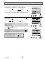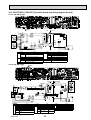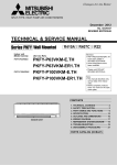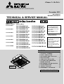
1
SPLIT-TYPE, HEAT PUMP AIR CONDITIONERS
December 2012
TECHNICAL & SERVICE MANUAL
Indoor unit
[Model names]
PLFY-P32VBM-E
PLFY-P40VBM-E
PLFY-P50VBM-E
PLFY-P63VBM-E
PLFY-P80VBM-E
PLFY-P100VBM-E
PLFY-P125VBM-E
[Service Ref.]
PLFY-P32VBM-E.UK
PLFY-P32VBM-ER2.UK
PLFY-P40VBM-E.UK
PLFY-P40VBM-ER2.UK
PLFY-P50VBM-E.UK
PLFY-P50VBM-ER2.UK
PLFY-P63VBM-E.UK
PLFY-P63VBM-ER2.UK
PLFY-P80VBM-E.UK
PLFY-P80VBM-ER2.UK
PLFY-P100VBM-E.UK
PLFY-P100VBM-ER3.UK
PLFY-P125VBM-E.UK
PLFY-P125VBM-ER3.UK
PLFY-P32VBM-E1.UK
PLFY-P32VBM-ER3.UK
PLFY-P40VBM-E1.UK
PLFY-P40VBM-ER3.UK
PLFY-P50VBM-E1.UK
PLFY-P50VBM-ER3.UK
PLFY-P63VBM-E1.UK
PLFY-P63VBM-ER3.UK
PLFY-P80VBM-E1.UK
PLFY-P80VBM-ER3.UK
PLFY-P100VBM-ER2.UK
PLFY-P125VBM-ER2.UK
No. OCH413
REVISED EDITION-D
Revision:
• PLFY-P32/40/50/63/80/
100/125VBM-ER3 have
been added in REVISED
EDITION-D.
• Some descriptions have
been modified.
• Please void OCH413
REVISED EDITION-C.
Note:
• This manual does not cover
outdoor units.
When servicing them, please
refer to the outdoor unit’s
service manual.
• RoHS compliant products
have <G> mark on the spec
name plate.
CONTENTS
Model name
indication
INDOOR UNIT
1. TECHNICAL CHANGES......................... 2
2. SAFETY PRECAUTION..........................3
3. PART NAMES AND FUNCTIONS.......... 5
4. SPECIFICATIONS.................................13
5. 4-WAY AIR FLOW SYSTEM................. 18
6. OUTLINES AND DIMENSIONS............ 21
7. WIRING DIAGRAM............................... 22
8. REFRIGERANT SYSTEM DIAGRAM...... 24
9. TROUBLESHOOTING.......................... 25
10 . SPECIAL FUNCTION........................... 34
11. DISASSEMBLY PROCEDURE............. 41
PARTS CATALOG (OCB413)
1
TECHNICAL CHANGES
PLFY-P32VBM-ER2.UK
PLFY-P40VBM-ER2.UK
PLFY-P50VBM-ER2.UK
PLFY-P63VBM-ER2.UK
PLFY-P80VBM-ER2.UK
PLFY-P100VBM-ER2.UK
PLFY-P125VBM-ER2.UK
PLFY-P32VBM-ER3.UK
PLFY-P40VBM-ER3.UK
PLFY-P50VBM-ER3.UK
PLFY-P63VBM-ER3.UK
PLFY-P80VBM-ER3.UK
PLFY-P100VBM-ER3.UK
PLFY-P125VBM-ER3.UK
INDOOR CONTROLLER BOARD (I.B) has been changed. (S/W version up)
PLP-6BAJ (Automatic filter elevation panel, option)
The controller board (U.B) has been changed. (only for the panel but not for the service part)
PLFY-P32VBM-E1.UK
PLFY-P40VBM-E1.UK
PLFY-P50VBM-E1.UK
PLFY-P63VBM-E1.UK
PLFY-P80VBM-E1.UK
PLFY-P100VBM-E.UK
PLFY-P125VBM-E.UK
PLFY-P32VBM-ER2.UK
PLFY-P40VBM-ER2.UK
PLFY-P50VBM-ER2.UK
PLFY-P63VBM-ER2.UK
PLFY-P80VBM-ER2.UK
PLFY-P100VBM-ER2.UK
PLFY-P125VBM-ER2.UK
INDOOR CONTROLLER BOARD (I.B) has been changed. (S/W version up)
PLFY-P32VBM-E.UK
PLFY-P40VBM-E.UK
PLFY-P50VBM-E.UK
PLFY-P63VBM-E.UK
PLFY-P80VBM-E.UK
PLFY-P32VBM-E1.UK
PLFY-P40VBM-E1.UK
PLFY-P50VBM-E1.UK
PLFY-P63VBM-E1.UK
PLFY-P80VBM-E1.UK
FAN MOTOR (MF) has been changed.
TURBO FAN, NUT and WASHER have been changed.
OCH413D
2
2
SAFETY PRECAUTION
Cautions for units utilizing refrigerant R410A
Use the following tools specifically designed for
use with R410A refrigerant.
Do not use the existing refrigerant piping.
The old refrigerant and lubricant in the existing piping
contains a large amount of chlorine which may cause the
lubricant deterioration of the new unit.
The following tools are necessary to use R410A refrigerant.
Gauge manifold
Charge hose
Gas leak detector
Torque wrench
Use “low residual oil piping”
If there is a large amount of residual oil (hydraulic oil, etc.)
inside the piping and joints, deterioration of the lubricant
will result.
Tools for R410A
Flare tool
Size adjustment gauge
Vacuum pump adaptor
Electronic refrigerant
charging scale
Handle tools with care.
Store the piping indoors, and both ends of the
piping sealed until just before brazing.
(Leave elbow joints, etc. in their packaging.)
If dirt, dust or moisture enters into refrigerant cycle, that can
cause deterioration of refrigerant oil or malfunction of compressor.
If dirt, dust or moisture enters into refrigerant cycle, that can
cause deterioration of refrigerant oil or malfunction of compressor.
Do not use a charging cylinder.
If a charging cylinder is used, the composition of refrigerant will change and the efficiency will be lowered.
The refrigerant oil applied to flare and flange
connections must be ester oil, ether oil or
alkylbenzene oil in a small amount.
If large amount of mineral oil enters, that can cause deterioration of refrigerant oil etc.
Charge refrigerant from liquid phase of gas
cylinder.
If the refrigerant is charged from gas phase, composition
change may occur in refrigerant and the efficiency will be
lowered.
Never use any refrigerant other than that specified.
Doing so may cause a burst, an explosion, or fire when the
unit is being used, serviced, or disposed of.
Correct refrigerant is specified in the manuals and on the
spec labels provided with our products.
We will not be held responsible for mechanical failure,
system malfunction, unit breakdown or accidents caused
by failure to follow the instructions.
Ventilate the room if refrigerant leaks during
operation. If refrigerant comes into contact with
a flame, poisonous gases will be released.
Do not use refrigerant other than R410A.
If other refrigerant (R22 etc.) is used, chlorine in refrigerant can cause deterioration of refrigerant oil etc.
Use a vacuum pump with a reverse flow check
valve.
Vacuum pump oil may flow back into refrigerant cycle and
that can cause deterioration of refrigerant oil etc.
OCH413D
Use the specified refrigerant only.
3
[1] Cautions for service
(1) Perform service after recovering the refrigerant left in unit completely.
(2) Do not release refrigerant in the air.
(3) After completing service, charge the cycle with specified amount of refrigerant.
(4) When performing service, install a filter drier simultaneously.
Be sure to use a filter drier for new refrigerant.
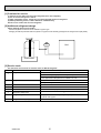
[2] Additional refrigerant charge
When charging directly from cylinder
· Check that cylinder for R410A on the market is syphon type.
· Charging should be performed with the cylinder of syphon stood vertically. (Refrigerant is charged from liquid phase.)
Unit
Gravimeter
[3] Service tools
Use the below service tools as exclusive tools for R410A refrigerant.
No.
1
Tool name
Gauge manifold
Specifications
· Only for R410A
· Use the existing fitting specifications. (UNF1/2)
· Use high-tension side pressure of 5.3MPa·G or over.
2
Charge hose
· Only for R410A
3
Electronic scale
4
Gas leak detector
· Use the detector for R134a, R407C or R410A.
5
Adaptor for reverse flow check
· Attach on vacuum pump.
6
Refrigerant charge base
7
Refrigerant cylinder
· Use pressure performance of 5.09MPa·G or over.
—
—
· Only for R410A
· Top of cylinder (Pink)
· Cylinder with syphon
8
Refrigerant recovery equipment
OCH413D
—
4
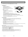
3
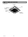
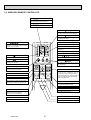
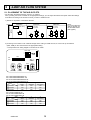
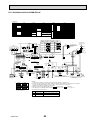
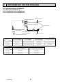
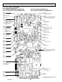
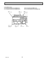
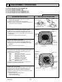
PART NAMES AND FUNCTIONS
3-1. INDOOR UNIT
Drain pipe
Filter
Air outlet
Liquid pipe
Gas pipe
i-see sensor
(option)
Vane
OCH413D
Air intake
(Intake grille)
5
3-2. WIRELESS REMOTE CONTROLLER
CHECK TEST RUN display
CHECK and TEST RUN display indicate that
the unit is being checked or test-run.
MODEL SELECT display
Blinks when model is selected.
display
Lights up while the signal is transmitted to
the indoor unit when the button is pressed.
display
SET TEMP. display indicates the desired
temperature which is set.
CLOCK display
display
Displays the current time.
OPERATION MODE display
Operation mode display indicates which
operation mode is in effect.
TIMER display
CHECK TEST RUN
MODEL SELECT
°C
AMPM
AMPM
display
The vertical direction of air flow is indicated.
NOT AVAILABLE
ON/OFF
Used to change the fan speed.
MODE SELECT button
” display
”“
” display
buttons
MODE
FAN
AUTO STOP
VANE
AUTO START
each time the button is pressed.
FAN SPEED SELECT button
”“
Displays whether timer is on or off.
display
ON/OFF button
“
Displays the order of timer operation.
“
TEMP
FAN SPEED display indicates which fan
speed has been selected.
The unit is turned ON and OFF alternately
Displays when in timer operation or when
setting timer.
CHECK LOUVER
TEST RUN
SET
h
min
RESET
SET TEMPERATURE button sets any desired
room temperature.
TIMER CONTROL buttons
AUTO STOP (OFF timer): when this switch
is set, the air conditioner will be
automatically stopped at the preset time.
AUTO START (ON timer): when this switch is
set, the air conditioner will be automatically
started at the preset time.
CLOCK
Used to switch the operation mode between
cooling, drying, heating, auto and fan mode.
h and min buttons
Buttons used to set the “hour and minute” of
the current time and timer settings.
LOUVER button
CHECK-TEST RUN buttons
Changes left/right airflow direction.
(Not available for this model.)
Only press this button to perform an
inspection check or test operation.
Do not use it for normal operation.
CLOCK button
VANE CONTROL button
RESET button
Used to change the air flow direction.
OCH413D
SET button
6
3-3. WIRED REMOTE CONTROLLER <PAR-30MAA/PAR-31MAA>
Wired remote controller function
* The functions which can be used are restricted according to the model.
Function
Body
: Supported
PAR-30MAA/PAR-31MAA
Slim
Product size H × W × D (mm)
LCD
: Unsupported
PAR-21MAA
City multi
120 × 120 × 19
120 × 130 × 19
Full Dot LCD
Partial Dot LCD
Backlight
Energy-saving
Energy-saving operation schedule
Automatic return to the preset temperature
Restriction
Setting the temperature range restriction
Function
Operation lock function
Weekly timer
On / Off timer
High Power
Manual vane angle
The functions of the function buttons change depending on
the screen. Refer to the button function guide that appears
at the bottom of the LCD for the functions they serve on a
given screen.
When the system is centrally controlled, the button function
guide that corresponds to the locked button will not appear.
<Main display>
<Main menu>
Fri
Room
Cool
Set temp.
Auto
Mode
Temp.
Fan
Function buttons
F1
F2
F3
Main menu
Vane·Louver·Vent. (Lossnay)
High power
Timer
Weekly timer
OU silent mode
Main display:
Cursor
Page
Function guide
F4
ON / OFF lamp
ON / OFF button
This lamp lights up in green while the unit is in operation.
It blinks while the remote controller is starting up or when
there is an error.
Press to turn ON/OFF the indoor unit.
SELECT button
Press to save the setting.
Function button F1
RETURN button
Main display : Press to change the operation mode.
Main menu : Press to move the cursor down.
Press to return to the previous screen.
Function button F2
MENU button
Main display : Press to decrease temperature.
Main menu : Press to move the cursor up.
Press to bring up the Main menu.
Backlit LCD
Operation settings will appear.
When the backlight is off, pressing any button turns the
backlight on and it will stay lit for a certain period of time
depending on the screen.
When the backlight is off, pressing any button turns
the backlight on and does not perform its function.
(except for the
(ON / OFF) button)
OCH413D
Main
7
Function button F3
Main display : Press to increase temperature.
Main menu : Press to go to the previous page.
Function button F4
Main display : Press to change the fan speed.
Main menu : Press to go to the next page.
The main display can be displayed in two different modes: "Full" and "Basic".
The factory setting is "Full". To switch to the "Basic" mode, change the setting on the Main display setting.
<Full mode>
<Basic mode>
* All icons are displayed for explanation.
Fri
Fri
Cool
Room
Cool
Set temp.
Mode
Temp.
Set temp.
Auto
Auto
Mode
Fan
Temp.
Fan
Operation mode
Indoor unit operation mode appears here.
Appears when the buttons are locked.
Preset temperature
Preset temperature appears here.
Clock (See the Installation Manual.)
Appears when the On/Off timer or Night setback function is
enabled.
Current time appears here.
Fan speed
Fan speed setting appears here.
Appears when the Weekly timer is enabled.
Button function guide
Functions of the corresponding buttons appear here.
Appears while the units are operated in the energy-save
mode.
Appears when the ON/OFF operation is centrally controlled.
Appears when the operation mode is centrally controlled.
Appears when the built-in thermistor on the remote controller is activated to monitor the room temperature (a).
appears when the thermistor on the indoor unit is activated to monitor the room temperature.
Appears when the preset temperature is centrally controlled.
Indicates the vane setting.
Appears when the f lter reset function is centrally controlled.
Indicates the louver setting.
Indicates when f lter needs maintenance.
Room temperature
(See the Installation Manual.)
Indicates the ventilation setting.
Current room temperature appears here.
Appears when the preset temperature range is restricted.
Most settings (except ON / OFF, mode, fan speed, temperature) can be made from the Menu screen.
OCH413D
8
Menu structure
Main menu
Press the MENU button.
Move the cursor to the desired item with the
F1
and
F2
buttons, and press the SELECT button.
Vane · Louver · Vent. (Lossnay)
High power
Timer
On / Off timer
Auto-Off timer
Filter information
Error information
Weekly timer
Energy saving
Auto return
Schedule
Night setback
Restriction
Temp. range
Operation lock
Maintenance
Auto descending panel
Manual vane angle
Initial setting
Main / Sub
Clock
Main display
Contrast
Display details
Auto mode
Administrator password
Language selection
Service
Service menu
Test run
Drain pump test run
Input maintenance info.
Function setting
Lossnay (City Multi only)
Check
Self check
Maintenance password
Remote controller check
Not all functions are available on all models of indoor units.
OCH413D
9
Main menu list
Setting and display items
Setting details
Vane · Louver · Vent.
(Lossnay)
Use to set the vane angle.
• Select a desired vane setting from f ve different settings.
Use to turn ON / OFF the louver.
• Select a desired setting from "ON" and "OFF."
Use to set the amount of ventilation.
• Select a desired setting from "Off," "Low," and "High."
High power
Use to reach the comfortable room temperature quickly.
• Units can be operated in the High-power mode for up to 30 minutes.
Timer
On/Off timer
Use to set the operation On/Off times.
• Time can be set in 5-minute increments.
* Clock setting is required.
Auto-Off
timer
Use to set the Auto-Off time.
• Time can be set to a value from 30 to 240 in 10-minute increments.
Filter information
Use to check the f lter status.
• The f lter sign can be reset.
Error information
Use to check error information when an error occurs.
• Error code, error source, refrigerant address, unit model, manufacturing number, contact
information (dealer's phone number) can be displayed.
* The unit model, manufacturing number, and contact information need to be registered in
advance to be displayed.
Weekly timer
Use to set the weekly operation On / Off times.
• Up to eight operation patterns can be set for each day.
* Clock setting is required.
* Not valid when the On/Off timer is enabled.
Energy
saving
Auto return
Use to get the units to operate at the preset temperature after performing energy-save
operation for a specif ed time period.
• Time can be set to a value from 30 and 120 in 10-minute increments.
* This function will not be valid when the preset temperature ranges are restricted.
Schedule
Set the start/stop times to operate the units in the energy-save mode for each day of the
week, and set the energy-saving rate.
• Up to four energy-save operation patterns can be set for each day.
• Time can be set in 5-minute increments.
• Energy-saving rate can be set to a value from 0% or 50 to 90% in 10% increments.
* Clock setting is required.
Night setback
Restriction
Use to make Night setback settings.
• Select "Yes" to enable the setting, and "No" to disable the setting. The temperature range and
the start/stop times can be set.
* Clock setting is required.
Temp. range
Use to restrict the preset temperature range.
• Different temperature ranges can be set for different operation modes.
Operation
lock
Use to lock selected functions.
• The locked functions cannot be operated.
Maintenance Auto
descending
panel
Manual
vane angle
Initial setting Main/Sub
Clock
Auto descending panel (Optional parts) Up / Down you can do.
Use to set the vane angle for each vane to a f xed position.
When connecting two remote controllers, one of them needs to be designated as a sub
controller.
Use to set the current time.
Main display Use to switch between "Full" and "Basic" modes for the Main display.
• The default setting is "Full."
Contrast
OCH413D
Use to adjust screen contrast.
10
Setting and display items
Initial setting Display
details
Auto mode
Setting details
Make the settings for the remote controller related items as necessary.
Clock: The factory settings are "Yes" and "24h" format.
Temperature: Set either Celsius (°C) or Fahrenheit (°F).
Room temp. : Set Show or Hide.
Auto mode: Set the Auto mode display or Only Auto display.
Whether or not to use the AUTO mode can be selected by using the button.
This setting is valid only when indoor units with the AUTO mode function are connected.
Administrator The administrator password is required to make the settings for the following items.
password
• Timer setting • Energy-save setting • Weekly timer setting
• Restriction setting • Outdoor unit silent mode setting • Night set back
Service
OCH413D
Language
selection
Test run
Use to select the desired language.
Select "Test run" from the Service menu to bring up the Test run menu.
• Test run • Drain pump test run
Input
Select "Input maintenance Info." from the Service menu to bring up the Maintenance
maintenance information screen.
The following settings can be made from the Maintenance Information screen.
• Model name input • Serial No. input • Dealer information input
Function
Make the settings for the indoor unit functions via the remote controller as necessary.
setting
This setting is required only when the operation of City Multi units is interlocked with
LOSSNAY
LOSSNAY units.
setting
(City Multi only)
Check
Error history: Display the error history and execute delete error history.
Refrigerant leak check: Refrigerant leaks can be judged.
Smooth maintenance: The indoor and outdoor maintenance data can be displayed.
Request cord: Details of the operation data including each thermistor temperature and error
history can be checked.
Self check
Error history of each unit can be checked via the remote controller.
Maintenance Take the following steps to change the maintenance password.
password
Remote
When the remote controller does not work properly, use the remote controller checking
controller
function to troublushoot the problem.
check
11
3-4. WIRED REMOTE CONTROLLER <PAR-21MAA>
“Sensor” indication
Display Section
For purposes of this explanation,
all parts of the display are shown.
During actual operation, only
the relevant items will be lit.
Identifies the current operation
Displayed when the remote controller
sensor is used.
Day-of-Week
Shows the current day of the week.
Time/Timer Display
“Locked” indicator
Shows the current time, unless the simple or Auto Off
timer is set.
If the simple or Auto Off timer is set, the time to be
switched off is shown.
Indicates that remote controller buttons have been locked.
“Clean The Filter” indicator
Shows the operating mode, etc.
*Multilanguage display is available.
To be displayed on when it is time to
clean the filter.
TIME SUN MON TUE WED THU FRI SAT
TIMER
Hr
ON
AFTER
Indicates that operation from the
remote controller has been prohibited by a master controller.
“Timer is Off” indicator
Indicates that the timer is off.
WEEKLY
SIMPLE
AUTO OFF
ONLY1Hr.
Shows the target temperature.
The indicator comes on if the corresponding timer is set.
Fan Speed indicator
Shows the selected fan speed.
Up/Down Air Direction indicator
The indicator shows the direction of the outcoming airflow.
“One Hour Only” indicator
Temperature Setting
FUNCTION
FILTER
°F°C
°F°C
“Centrally Controlled” indicator
Timer indicators
AFTER OFF
ERROR CODE
Displayed if the airflow is set to
low or downward during COOL
or DRY mode. (Operation varies
according to model.)
The indicator goes off in 1 hour,
when the airflow direction
also changes.
Room Temperature display
Shows the room temperature. The room
temperature display range is 8 - 39.
The display blinks if the temperature
is less than 8 or 39 or more.
Ventilation indicator
Appears when the unit is running in
Ventilation mode.
Louver display
Indicates the action of the swing louver.
Does not appear if the louver is not
running
(Power On indicator)
Indicates that the power is on.
Operation Section
ON/OFF button
Temperature setting buttons
Down
Fan Speed button
Up
Timer Menu button
(Monitor/Set button)
Filter
button
(<Enter> button)
Mode button (Return button)
TEMP.
ON/OFF
Set Time buttons
Check button (Clear button)
Back
Ahead
Timer On/Off button
(Set Day button)
Test Run button
MENU
BACK
PAR-21MAA
MONITOR/SET
ON/OFF
FILTER
DAY
CHECK TEST
OPERATION
CLOCK
CLEAR
Airflow Up/Down button
Louver button
(
Operation button)
To return operation
number
Opening the
cover
Built-in temperature sensor
Ventilation button
( Operation button)
To go to next operation
number
Note:
● “PLEASE WAIT” message
This message is displayed for approximately 3 minutes when power is supplied to the indoor unit or when the unit is recovering from a power failure.
● “NOT AVAILABLE” message
This message is displayed if an invalid button is pressed (to operate a function that the indoor unit does not have).
If a single remote controller is used to operate multiple indoor units simultaneously that are different types, this message will not be displayed as
far as any of the indoor units is equipped with the function.
OCH413D
12
4
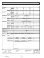
SPECIFICATIONS
4-1. SPECIFICATIONS
Model
1
1
1
2
Power input
Current input
Heating capacity
(Nominal )
3
3
3
Power input
Current input
External finish
External dimension H × W × D
Net weight
Decoration panel
Heat exchanger
FAN
Model
External finish
Dimension
H×W×D
Net weight
Type × Quantity
External
static press.
Motor type
Motor output
Driving mechanism
Airflow rate
(Low-Mid2Mid1-High)
Noise level (Low-Mid2-Mid1-High)
(measured in anechoic room)
Insulation material
Air filter
Protection device
Refrigerant control device
Connectable outdoor unit
Liquid
Diameter of
refrigerant pipe
Gas
Field drain pipe size
Document
Standard
Accessory
attachment
Remark
PLFY-P40VBM-E
PLFY-P32VBM-E
Power source
Cooling capacity
(Nominal)
kW
kcal / h
Btu / h
kcal / h
kW
A
kW
kcal / h
Btu / h
kW
A
3.6
3,100
12,300
3,150
0.03
0.22
4.0
3,400
13,600
0.02
0.14
mm
in.
kg (lb)
22 (49)
PLP-6BA
mm
in.
kg (lb)
Turbo fan × 1
0
0
Pa
mmH2O
kW
m3 / min
L/s
cfm
dB <A>
0.050
11 - 12 - 13 - 14
183 - 200 - 217 - 233
388 - 424 - 459 - 494
27 - 28 - 29 - 31
PLFY-P50VBM-E
1-phase 220-240V 50Hz, 1-phase 220V 60Hz
5.6
4.5
4,800
3,900
19,100
15,400
5,000
4,000
0.04
0.04
0.29
0.29
6.3
5.0
5,400
4,300
21,500
17,100
0.03
0.03
0.22
0.22
Galvanized steel sheet
258 x 840 x 840
10-3/16 x 33-1/8 x 33-1/8
22 (49)
22 (49)
PLP-6BA
PLP-6BA
MUNSELL (6.4Y 8.9/0.4)
35 x 950 x 950
1-3/8 x 37-7/16 x 37-7/16
6 (13)
Cross fin (Aluminum fin and copper tube)
Turbo fan × 1
Turbo fan × 1
0
0
0
0
DC motor
0.050
0.050
Direct-drive
12 - 13 - 14 - 16
12 - 13 - 14 - 16
200 - 217 - 233 - 267
200 - 217 - 233 - 267
424 - 459 - 494 - 565
424 - 459 - 494 - 565
27 - 28 - 30 - 31
27 - 28 - 30 - 31
mm (in.)
:6.35 (:1/4)
Flare
PS
PP honeycomb
Fuse
LEV
R410A CITY MULTI
Flare
:6.35 (:1/4)
:6.35 (:1/4)
mm (in.)
:12.7 (:1/2)
Flare
:12.7 (:1/2)
Flare
:12.7 (:1/2)
PLFY-P63VBM-E
7.1
6,100
24,200
6,300
0.05
0.36
8.0
6,900
27,300
0.04
0.29
23 (51)
PLP-6BA
Turbo fan × 1
0
0
0.050
14 - 15 - 16 - 18
233 - 250 - 267 - 300
494 - 530 - 565 - 636
28 - 29 - 30 - 32
Flare
:9.52 (:3/8)
Flare
Flare
:15.88 (:5/8)
Flare
O.D. :32 (VP-25)
mm (in.)
Installation Manual, Instruction Book
Optional parts
Decoration panel **1
Air outlet shutter plate
High efficiency filter
element **2
Multi-function casement
PLP-6BA
PAC-SH51SP-E
PAC-SH59KF-E
PLP-6BA
PAC-SH51SP-E
PAC-SH59KF-E
PLP-6BA
PAC-SH51SP-E
PAC-SH59KF-E
PLP-6BA
PAC-SH51SP-E
PAC-SH59KF-E
PAC-SH53TM-E
PAC-SH53TM-E
PAC-SH53TM-E
PAC-SH53TM-E
**1. PLFY-P-VBM-E should use together with PLP-6BA.
**2. PAC-SH53TM-E is necessary to use with filter PAC-SH59KF-E.
Installation
Note :
Indoor :
Outdoor :
Pipe length :
Level difference :
Details on foundation work, duct work, insulation work, electrical wiring, power source switch, and other items shall be referred to
the Installation Manual.
1 Nominal cooling conditions
27DB/19WB (81°FDB/66°FWB)
35DB (95°FDB)
7.5 m (24-9/16 ft)
0 m (0 ft)
2 Nominal cooling conditions
27DB/19.5WB (81°FDB/67°FWB)
35DB (95°FDB)
5 m (16-3/8 ft)
0 m (0 ft)
Unit converter
kcal/h
Btu/h
cfm
lb
= kW × 860
= kW × 3,412
= m3/min × 35.31
= kg / 0.4536
*Above specification data is
subject to rounding variation.
* Nominal conditions 1, 3 are subject to JIS B8615-1.
* Due to continuing improvement, above specification may be subject to change without notice.
OCH413D
3 Nominal heating conditions
20DB (68°FDB)
7DB/6WB (45°FDB/43°FWB)
7.5 m (24-9/16 ft)
0 m (0 ft)
13
Model
PLFY-P80VBM-E
Power source
Cooling capacity
(Nominal)
1
1
1
2
Power input
Current input
Heating capacity
(Nominal )
3
3
3
Power input
Current input
External finish
External dimension H × W × D
Net weight
Decoration panel
Heat exchanger
FAN
Model
External finish
Dimension
H×W×D
Net weight
Type × Quantity
External
static press.
Motor type
Motor output
Driving mechanism
Airflow rate
(Low-Mid2Mid1-High)
Noise level (Low-Mid2-Mid1-High)
(measured in anechoic room)
Insulation material
Air filter
Protection device
Refrigerant control device
Connectable outdoor unit
Liquid
Diameter of
refrigerant pipe
Gas
Field drain pipe size
Document
Standard
Accessory
attachment
9.0
7,700
30,700
8,000
0.07
0.51
10.0
8,600
34,100
0.06
0.43
mm
in.
kg (lb)
258 x 840 x 840
23(51)
PLP-6BA
mm
in.
kg (lb)
Turbo fan x 1
0
0
kW
mm (in.)
mm (in.)
mm (in.)
0.050
16 - 18 - 20 - 22
267 - 300 - 333 - 367
565 - 636 - 706 - 777
30 - 32 - 35 - 37
:9.52 (:3/8)
:15.88 (:5/8)
Flare
Flare
11-3/4 x 33-1/8 x 33-1/8
27(60)
27(60)
PLP-6BA
PLP-6BA
MUNSELL (6.4Y 8.9/0.4)
35 x 950 x 950
1-3/8 x 37-7/16 x 37-7/16
6(13)
Cross fin (Aluminum fin and copper tube)
Turbo fan x 1
Turbo fan x 1
0
0
0
0
DC motor
0.120
0.120
Direct-drive
22 - 25 - 28 - 30
21 - 24 - 27 - 29
367 - 417 - 467 - 500
350 - 400 - 450 - 483
777 - 883 - 989 - 1059
742 - 848 - 953 - 1024
35 - 38 - 41 - 43
34 - 37 - 39- 41
PS
PP honeycomb
Fuse
LEV
R410A CITY MULTI
:9.52 (:3/8)
Flare
:9.52 (:3/8)
:15.88 (:5/8)
Flare
:15.88 (:5/8)
O.D. :32 (VP-25)
Flare
Flare
Installation Manual, Instruction Book
Optional parts
Decoration panel **1
Air outlet shutter plate
High efficiency filter
element **2
Multi-function casement
Remark
Galvanized steel sheet
298 x 840 x 840
10-3/16 x 33-1/8 x 33-1/8
Pa
mmH2O
PLFY-P125VBM-E
1-phase 220-240V 50Hz, 1-phase 220V 60Hz
14.0
11.2
12,000
9,600
47,800
38,200
12,500
10,000
0.16
0.15
1.07
1.00
16.0
12.5
13,800
10,800
54,600
42,700
0.15
0.14
1.00
0.94
kW
kcal / h
Btu / h
kcal / h
kW
A
kW
kcal / h
Btu / h
kW
A
m3 / min
L/s
cfm
dB <A>
PLFY-P100VBM-E
PLP-6BA
PAC-SH51SP-E
PAC-SH59KF-E
PLP-6BA
PAC-SH51SP-E
PAC-SH59KF-E
PLP-6BA
PAC-SH51SP-E
PAC-SH59KF-E
PAC-SH53TM-E
PAC-SH53TM-E
PAC-SH53TM-E
**1. PLFY-P-VBM-E should use together with PLP-6BA.
**2. PAC-SH53TM-E is necessary to use with filter PAC-SH59KF-E.
Installation
Note :
Indoor :
Outdoor :
Pipe length :
Level difference :
Details on foundation work, duct work, insulation work, electrical wiring, power source switch, and other items shall be referred to
the Installation Manual.
1 Nominal cooling conditions
27DB/19WB (81°FDB/66°FWB)
35DB (95°FDB)
7.5 m (24-9/16 ft)
0 m (0 ft)
2 Nominal cooling conditions
27DB/19.5WB (81°FDB/67°FWB)
35DB (95°FDB)
5 m (16-3/8 ft)
0 m (0 ft)
Unit converter
kcal/h
Btu/h
cfm
lb
= kW × 860
= kW × 3,412
= m3/min × 35.31
= kg / 0.4536
*Above specification data is
subject to rounding variation.
* Nominal conditions 1, 3 are subject to JIS B8615-1.
* Due to continuing improvement, above specification may be subject to change without notice.
OCH413D
3 Nominal heating conditions
20DB (68°FDB)
7DB/6CWB (45°FDB/43°FWB)
7.5 m (24-9/16 ft)
0 m (0 ft)
14
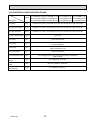
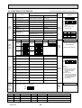
4-2. ELECTRICAL PARTS SPECIFICATIONS
Service Ref.
Parts name
PLFY-P32VBM-E.UK
PLFY-P32VBM-E
1.UK
Symbol
PLFY-P32VBM-ER2.UK
PLFY-P32VBM-ER3.UK
PLFY-P40VBM-E.UK
PLFY-P40VBM-E1.UK
PLFY-P40VBM-ER2.UK
PLFY-P40VBM-ER3.UK
PLFY-P50VBM-E.UK
PLFY-P50VBM-E1.UK
PLFY-P50VBM-ER2.UK
PLFY-P50VBM-ER3.UK
PLFY-P63VBM-E.UK
PLFY-P63VBM-E1.UK
PLFY-P63VBM-ER2.UK
PLFY-P63VBM-ER3.UK
Room temperature
thermistor
TH21
Resistance 0/15k, 10/9.6k, 20/6.3k, 25/5.4k, 30/4.3k, 40/3.0k
Liquid pipe thermistor
TH22
Resistance 0/15k, 10/9.6k, 20/6.3k, 25/5.4k, 30/4.3k, 40/3.0k
Gas pipe thermistor
TH23
Resistance 0/15k, 10/9.6k, 20/6.3k, 25/5.4k, 30/4.3k, 40/3.0k
Fuse
(Indoor controller board)
FUSE
250V 6.3A
Fan motor
MF
8-pole OUTPUT 50W
Vane motor
MV
MSBPC20M04
DC12V 300/phase
Drain pump
DP
PLD-12230ME-1
INPUT 12/10.8W 241/Hr
Drain float switch
FS
open/short detection
Linear expansion valve
LEV
DC12V Stepping motor drive port dimension :5.2 (0~2000pulse)
EDM-40YGME
Power supply terminal
block
TB2
(L, N, ) Rated to 330V 30A *
Transmission terminal
block
TB5
(M1, M2, S) Rated to 250V 20A *
MA remote controller
terminal block
TB15
(1, 2) Rated to 250V 10A *
* Note: Refer to WIRING DIAGRAM for the supplied voltage.
OCH413D
15
Service Ref.
Symbol
Parts name
PLFY-P80VBM-E.UK
PLFY-P80VBM-E1.UK
PLFY-P80VBM-ER2.UK
PLFY-P80VBM-ER3.UK
PLFY-P100VBM-E.UK
PLFY-P100VBM-ER2.UK
PLFY-P100VBM-ER3.UK
PLFY-P125VBM-E.UK
PLFY-P125VBM-ER2.UK
PLFY-P125VBM-ER3.UK
Room temperature
thermistor
TH21
Resistance 0/15k, 10/9.6k, 20/6.3k, 25/5.4k, 30/4.3k, 40/3.0k
Liquid pipe thermistor
TH22
Resistance 0/15k, 10/9.6k, 20/6.3k, 25/5.4k, 30/4.3k, 40/3.0k
Gas pipe thermistor
TH23
Resistance 0/15k, 10/9.6k, 20/6.3k, 25/5.4k, 30/4.3k, 40/3.0k
Fuse
(Indoor controller board)
FUSE
250V 6.3A
8-pole OUTPUT 50W
8-pole OUTPUT 120W
Fan motor
MF
Vane motor
MV
MSBPC20M04
DC12V 300/phase
Drain pump
DP
PLD-12230ME-1
INPUT 12/10.8W 241/Hr
Drain float switch
FS
open/short detection
Linear expansion valve
LEV
DC12V Stepping motor drive port dimension :5.2 (0~2000pulse)
EDM-80YGME
Power supply terminal
block
TB2
(L, N, ) Rated to 330V 30A *
Transmission terminal
block
TB5
(M1, M2, S) Rated to 250V 20A *
MA remote controller
terminal block
TB15
(1, 2) Rated to 250V 10A *
* Note: Refer to WIRING DIAGRAM for the supplied voltage.
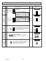
4-3. SOUND LEVEL
PLFY-P·VBM-E
1.5m
Service Ref.
Measurement location
* Measured in anechoic room.
OCH413D
PLFY-P32VBM-E(1).UK
PLFY-P32VBM-ER2.UK
PLFY-P32VBM-ER3.UK
PLFY-P40VBM-E(1).UK
PLFY-P40VBM-ER2.UK
PLFY-P40VBM-ER3.UK
PLFY-P50VBM-E(1).UK
PLFY-P50VBM-ER2.UK
PLFY-P50VBM-ER3.UK
PLFY-P63VBM-E(1).UK
PLFY-P63VBM-ER2.UK
PLFY-P63VBM-ER3.UK
PLFY-P80VBM-E(1).UK
PLFY-P80VBM-ER2.UK
PLFY-P80VBM-ER3.UK
PLFY-P100VBM-E.UK
PLFY-P100VBM-ER2.UK
PLFY-P100VBM-ER3.UK
PLFY-P125VBM-E.UK
PLFY-P125VBM-ER2.UK
PLFY-P125VBM-ER3.UK
16
Sound level at anechoic room : Low-Mid2-Mid1-High
Sound level dB (A)
27-28-29-31
27-28-30-31
28-29-30-32
30-32-35-37
34-37-39-41
35-38-41-43
4-4. NC CURVES
65.0
60.0
NC-60
55.0
50.0
NC-50
45.0
40.0
NC-40
35.0
30.0
NC-30
25.0
20.0
15.0
10.0
63
Approximate minimum
audible limit on
continuous noise
125
250
NC-20
500
1k
2k
4k
8k
60.0
50.0
40.0
NC-60
50.0
NC-50
45.0
40.0
NC-40
35.0
30.0
NC-30
25.0
20.0
15.0
10.0
63
Approximate minimum
audible limit on
continuous noise
125
250
NC-20
500
1k
2k
4k
NC-40
35.0
30.0
NC-30
25.0
20.0
15.0
10.0
63
Approximate minimum
audible limit on
continuous noise
125
250
NC-20
500
8k
Octave band center frequencies (Hz)
High 50/60Hz
Low 50/60Hz
50.0
NC-50
45.0
40.0
NC-40
35.0
30.0
NC-30
25.0
20.0
15.0
10.0
63
Approximate minimum
audible limit on
continuous noise
125
250
NC-20
500
Octave band pressure level (dB) 0dB=20Pa
40.0
NC-40
35.0
30.0
NC-30
25.0
20.0
15.0
10.0
63
Approximate minimum
audible limit on
continuous noise
125
250
NC-20
500
1k
2k
4k
8k
Octave band center frequencies (Hz)
OCH413D
1k
2k
4k
Octave band center frequencies (Hz)
NC-50
45.0
65.0
60.0
17
NC-60
55.0
50.0
NC-50
45.0
40.0
NC-40
35.0
30.0
NC-30
25.0
20.0
15.0
10.0
63
Approximate minimum
audible limit on
continuous noise
125
250
NC-20
500
1k
2k
4k
8k
PLFY-P100VBM-E.UK
PLFY-P100VBM-ER2.UK
PLFY-P100VBM-ER3.UK
External static pressure : 0Pa
Power source : 220,230,240V, 50Hz / 220V, 60Hz
Middle2 50/60Hz
Middle1 50/60Hz
NC-60
NC-60
50.0
8k
Middle2 50/60Hz
Middle1 50/60Hz
Octave band center frequencies (Hz)
55.0
65.0
55.0
4k
60.0
Middle2 50/60Hz
Middle1 50/60Hz
60.0
2k
65.0
PLFY-P125VBM-E.UK
PLFY-P125VBM-ER2.UK
PLFY-P125VBM-ER3.UK
External static pressure : 0Pa
Power source : 220,230,240V, 50Hz / 220V, 60Hz
70.0
1k
High 50/60Hz
Low 50/60Hz
70.0
Octave band pressure level (dB) 0dB=20Pa
Octave band pressure level (dB) 0dB=20Pa
65.0
55.0
NC-50
45.0
PLFY-P80VBM-E(1).UK
PLFY-P80VBM-ER2.UK
PLFY-P80VBM-ER3.UK
External static pressure : 0Pa
Power source : 220,230,240V, 50Hz / 220V, 60Hz
Middle2 50/60Hz
Middle1 50/60Hz
60.0
NC-60
55.0
High 50/60Hz
Low 50/60Hz
70.0
Octave band center frequencies (Hz)
PLFY-P63VBM-E(1).UK
PLFY-P63VBM-ER2.UK
PLFY-P63VBM-ER3.UK
External static pressure : 0Pa
Power source : 220,230,240V, 50Hz / 220V, 60Hz
High 50/60Hz
Low 50/60Hz
Middle2 50/60Hz
Middle1 50/60Hz
65.0
Octave band center frequencies (Hz)
70.0
High 50/60Hz
Low 50/60Hz
70.0
PLFY-P50VBM-E(1).UK
PLFY-P50VBM-ER2.UK
PLFY-P50VBM-ER3.UK
External static pressure : 0Pa
Power source : 220,230,240V, 50Hz / 220V, 60Hz
8k
High 50/60Hz
Low 50/60Hz
70.0
Octave band pressure level (dB) 0dB=20Pa
Octave band pressure level (dB) 0dB=20Pa
Middle2 50/60Hz
Middle1 50/60Hz
Octave band pressure level (dB) 0dB=20Pa
High 50/60Hz
Low 50/60Hz
70.0
PLFY-P40VBM-E(1).UK
PLFY-P40VBM-ER2.UK
PLFY-P40VBM-ER3.UK
External static pressure : 0Pa
Power source : 220,230,240V, 50Hz / 220V, 60Hz
Octave band pressure level (dB) 0dB=20Pa
PLFY-P32VBM-E(1).UK
PLFY-P32VBM-ER2.UK
PLFY-P32VBM-ER3.UK
External static pressure : 0Pa
Power source : 220,230,240V, 50Hz / 220V, 60Hz
Middle2 50/60Hz
Middle1 50/60Hz
65.0
60.0
NC-60
55.0
50.0
NC-50
45.0
40.0
NC-40
35.0
30.0
NC-30
25.0
20.0
15.0
10.0
63
Approximate minimum
audible limit on
continuous noise
125
250
NC-20
500
1k
2k
4k
Octave band center frequencies (Hz)
8k
5
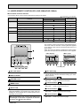
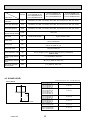
4-WAY AIR FLOW SYSTEM
5-1. PLACEMENT OF THE AIR OUTLETS
• For this grille, the blowout direction comes in 11 patterns.
Also, by setting the remote controller to the appropriate settings, you can adjust the airflow and speed. Select the settings
from Table1 according to the location in which you want to install the unit.
1) Decide on the pattern of the airflow direction.
<Table 1>
4-direction
Blowout direction
pattern
Pattern 1
3-direction
Initial setting
Pattern 4
2-direction
1 air outlet
fully closed
Pattern 6
2 air outlet
fully closed
Note1.
For 3 and 2-direction
settings, please use
the air outlet shutter
plate (option).
2) According to the number of air outlets and height of the ceiling to install the unit, be sure to set up the switches
(SWA, SWB) on the circuit board to the appropriate setting.
• Correspondence of ceiling heights to numbers of air outlets
SWA SWB
3
2
1
SW1
2
3
4
CN43
ON
OFF
CN82
1 2 3 4 5 6 7 8 9 10
SW11
7 8
7 8
4
5 6
(1s DIGIT)
5 6
PLFY-P32/40/50/63/80VBM-E.UK
PLFY-P32/40/50/63/80VBM-E1.UK
PLFY-P32/40/50/63/80VBM-ER2.UK
PLFY-P32/40/50/63/80VBM-ER3.UK
SWA
SWB
4 direction
3 direction
2 direction
Silent
2.5m
2.7m
3.0m
PLFY-P100/125VBM-E.UK
PLFY-P100/125VBM-ER2.UK
PLFY-P100/125VBM-ER3.UK
SWA
SWB
4 direction
3 direction
2 direction
OCH413D
SW14
E
F0 1 2
3456
2 3
2 3
(10ths DIGIT)
SWC
0 1
D
9
BC
0 1
4
9
789A
SW12
Silent
2.7m
3.0m
3.3m
./
.
(BRANCH No.)
Standard
2.7m
3.0m
3.3m
High ceiling
3.5m
3.5m
3.5m
Standard
3.2m
3.6m
4.0m
High ceiling
4.5m
4.5m
4.5m
18
5-2. BRANCH DUCT HOLE AND FRESH AIR INTAKE HOLE
At the time of installation, use the duct holes (cut out) located at the positions shown in following diagram, as and when
required.
• A fresh air intake hole for the optional multi function casement can also be made.
Note:
The figures marked with * in the drawing below represent the dimensions of the main unit excluding those of the optional multi
function casement.
When installing the optional multi function casement, add 135 mm to the dimensions marked on the figure.
When installing the branch ducts, be sure to insulate adequately.
Otherwise, condensation and dripping may occur.
Fresh air intake hole diagram
Fresh air intake hole
3-:2.8 burring hole
:125 burring
120
hole pitch
Branch duct hole diagram
(view from either side)
100
100
90
Ceiling
100
90
:100 cut
out hole
Drain pipe
130
*158
70°
*155
Refrigerant pipe
:175 burring hole pitch
5-3. OPERATION IN CONJUNCTION WITH
DUCT FAN (Booster fan)
• Whenever the indoor unit is operating, the duct fun also
operates.
(1) Connect the optional multiple remote controller adapter
(PAC-SA88HA-E) to the connector CN51 on the indoor
controller board.
(2) Drive the relay after connecting the 12V DC relay
between the Yellow and Orange connector wires.
MB: Electromagnetic switch power relay for duct fan.
X: Auxiliary relay (For DC 12V, coil rating : 1.0W or below)
14-:2.8 burring hole
:150 cut out hole
350
~
Be sure to secure insulation
material by tape, etc
CN51
Green
5
on
Yellow
indoor
controller
MB
Orange
1
Connector (5P)
board
Red
Brown
Indoor unit side
Installation at site
Multiple remote
controller adapter
Be sure to secure insulation
PAC-SA88HA-E
material by tape, etc
Indoor controller board
CN51
Multiple remote
controller adapter
PAC-SA88HA-E
CN51
OCH413D
19
*167
Indoor unit
120
Branch duct hole
Distance between indoor
controller board and relay
must be within 10m.
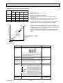
5-4. FRESH AIR INTAKE AMOUNT & STATIC PRESSURE CHARACTERISTICS
l PLFY-P32/40/50/63/80VBM-E.UK
Multi function casement + High efficiency filter
50
50
0
0
Static pressure[Pa]
Static pressure[Pa]
PLFY-P32/40/50/63/80VBM-E1.UK
PLFY-P32/40/50/63/80VBM-ER2.UK
PLFY-P32/40/50/63/80VBM-ER3.UK
Multi function casement + Standard filter
-50
2 - inlet
-100
-150
-50
2 - inlet
-100
-150
1 - inlet
1 - inlet
-200
0
1
2
3
4
5
-200
6
0
1
2
3
Airflow rate [m3/min]
Airflow rate [m3/min]
Taking air into the unit
A
Q
-100
B
-50
C
0
Duct characteristics
at site
C
A
2
-150
E
Static pressure[Pa]
Curve in the
graphs
1
0
Q
0
1
2
3
4
5
6
Airflow rate [m3/min]
A
D
3
PLFY-P100/125VBM-ER2.UK
PLFY-P100/125VBM-ER3.UK
Multi function casement + Standard filter
50
-50
2 - inlet
-100
-150
Static pressure[Pa]
Static pressure[Pa]
0
0
-50
-100
2 - inlet
-150
1 - inlet
2
4
Airflow rate [m3/min]
1 - inlet
6
8
6
8
-200
Taking air into the unit
50
Static pressure[Pa]
0
-50
-100
-150
-200
0
2
4
Airflow rate [m3/min]
OCH413D
Q…Planned amount of fresh air intake
<m3/min>
A…Static pressure loss of fresh air
intake duct system with airflow
amount Q
<Pa>
…
B Forced static pressure at air conditioner inlet with airflow amount Q
<Pa>
C…Static pressure of booster fan with
airflow amount Q
<Pa>
D … Static pressure loss increase
amount of fresh air intake duct system for airflow amount Q
<Pa>
E…Static pressure of indoor unit with
airflow amount Q
<Pa>
Qa…Estimated amount of fresh air
3
intake without D
<m /min>
Multi function casement + High efficiency filter
50
0
6
Q
Qa
2 PLFY-P100/125VBM-E.UK
-200
5
How to read curves
50
-200
4
20
0
2
4
Airflow rate [m3/min]
6
8
6
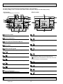
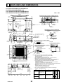
OUTLINES AND DIMENSIONS
PLFY-P32/40/50/63/80/100/125VBM-E.UK
PLFY-P32/40/50/63/80VBM-E1.UK
PLFY-P32/40/50/63/80/100/125VBM-ER2.UK
PLFY-P32/40/50/63/80/100/125VBM-ER3.UK
860~910
20~45
Detail connecting of branch duct(Both aspects)
810
Suspension bolt pitch
90
100
100
90
Cut out hole
860~910
20~45
B
A
190
167
Ceiling
Auto-grille
Air intake grille up/down distance
In case of auto-grille : PLP-6BAJ
In case of wireless remote controller : PLP-6BALM
Emergency operation switch<Cooling>
and Emergency Up/Down switch<Up>
Emergency operation
switch<Heating>and
Emergency Up/Down switch<Down>
Ceiling
L.L Filter
597
83
M
36
500
Air outlet hole
Vane motor
83
36
Indoor unit
1000 mm
or more
Indoor unit
3000 mm or
more
Obstacle
2500mm or more
from floor
For high
attachment
Air intake grille
Models
A
B
C
D
E
PLFY-P32,40, 50VBM-E
Refrigerant pipe···:6.35
Flared connection···1/4 inch
Refrigerant pipe ···:12.7
Flared connection···1/2 inch
80 74
400
241 258
Floor
PLFY-P63,80VBM-E
Refrigerant pipe···:9.52
PLFY-P100,125VBM-E Flared connection···3/8 inch
OCH413D
:100
Note 1. Please choose the grille from a standard grille, auto-grille.
2. As for drain pipe, please use VP-25 (O.D. :32 PVC TUBE).
Drain pump is included.
Max. lifting height is 850mm from the ceiling.
3. As for suspension bolt, please use M10 or W3/8. (Procured at local site)
4. Electrical box may be removed for the service purpose.
Make sure to slack the electrical wire little bit for control/power wires connection.
5. The height of the indoor unit is able to be adjusted with the grille attached.
6. For the installation of the optional high efficiency filter or optional
multi-functional casement.
1) Requires E or more space between transom and ceiling for the installation.
2) Add 135 mm to the dimensions * marked on the figure.
3) The optional high efficiency filter must be used jointly with optional multi-functional
casement.
7. When installing the branch ducts, be sure to insulate adequately.
Otherwise condensation and dripping may occur.
(It becomes the cause of dew drops/water dew.)
8. As for necessary installation/service space, please refer to the left figure.
Accessory ··· Drain socket (I.D. 32)
Corner pocket
1500 mm
or more
Cut out hole
*
DEFROST/STAND BY lamp
Receiver
Operation lamp
950
Grille
)
35
Auto vane
(Air outlet)
M
Ceiling
:125
In case of standard grille : PLP-6BA/PLP-6BAMD
Air intake hole
500
Air outlet hole
950
M
Air intake
grille
*
*
Drain hole
Drain pump clean hole
and Drain emergency
drainage hole
M
Connected the attached
flexible pipe or socket.
Keep approximately
10 to 15 mm space
between unit ceiling
and ceiling slab.
597
Air intake hole
(
17
Ceiling
Grille
*
+5
0
Power supply wire,
Indoor unit/Outdoor unit
connecting wire entry
*
Control wire entry
156
105
140
50~70
170
*
Burring hole pitch
120°
Drain pipe
connected to VP-25
377
*
Suspension bolt
lower edge
* 155
Burring hole
3-:2.8
2
*
:150
120°
284
Burring hole
158
60
14-:2.8
Detail drawing of fresh air intake hole
840
1
350
:175
Burring hole pitch
Cut out hole
160
187.5
Branch duct hole
*
Max. 4.0m
24
160
D
C
90
Suspension bolt
M10 or W3/8
Ceiling hole
840
150
For MA-Remote controller
terminal block
620
Suspension bolt pitch
Power supply
terminal block
Branch duct hole
(7.5)
Indoor/outdoor unit connecting
terminal block
605
70°
160
(7.5)
100
160
20~45
Fresh air
intake hole
130
Ceiling hole
20~45
Unit : mm
21
Refrigerant pipe···:15.88
Flared connection···5/8 inch
281 298
85 77
440
7
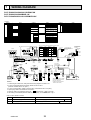
WIRING DIAGRAM
PLFY-P32/40/50/63/80/100/125VBM-E.UK
PLFY-P32/40/50/63/80VBM-E1.UK
PLFY-P32/40/50/63/80/100/125VBM-ER2.UK
[LEGEND]
NAME
INDOOR CONTROLLER BOARD
CONNECTOR DAMPER
REMOTE SWITCH
CENTRALLY CONTROL
REMOTE INDICATION
FUSE (T6.3AL250V)
POWER SUPPLY (I. B)
POWER SUPPLY (I. B)
CAPACITY CODE
SWITCH
MODE SELECTION
MODEL SELECTION
DRAIN PUMP (TEST MODE)
AUX. RELAY
DRAIN PUMP
DRAIN PUMP
DRAIN FLOAT SWITCH
LINEAR EXPANSION VALVE
FAN MOTOR
VANE MOTOR
A.B
5 6
5
5
TH22
TH23
A. B
SWA
SWB
SWC
SW1
SW11
SW12
SW14
10ths
DIGIT
5
BCD
7 8
1s
DIGIT
BRANCH
No.
1
19 17 15 13 11 9 7 5 3 1
1
CN52
1 (GRN) 5
M
1
8
ADDRESS
CN81
(RED)
ON
OFF
P63
ON
OFF
1 2 3 4 5 6
1 2 3 4 5 6
WIRELESS
CN90
(WHT)
4
ON
OFF
ADDRESS
CN42
(RED)
9
1 (WHT) 4
9
TO MA-REMOTE
CONTROLLER
DC8.7-13V
M
W.B
LEV
P100
ON
OFF
P125
ON
OFF
LED2
SW2
LED1
RU
FUSE(16A)
1 2 3 4 5 6
SW3
SW4
12345678910
SW2
12345 123456
13 5
ON
OFF
DC311~339V
RECTIFICATION
7
FAN
CNMF
(WHT)
t°
t°
FS
TH21
CND
(BLK)
2 1
M-NET
CN2M
(BLU)
SWE
CN25
1 3 (WHT)
AUTO GRILLE
1 2
CN3G
LED1
(BLK)
INTAKE
FLOAT SW
CN27
CN20
CN4F
(RED) (RED)
1 2
1 2
1 (WHT) 4
4
FUSE
AUTO GRILLE POWER
CNAC
(WHT)
X1
1
MF
D.U.M 3
CNP
(BLU)
1
3 1
3
M
DP
3
1
CN3G
* Be sure to turn off the power
source and then disconnect
fan motor connector.
(Failure to do so will cause
trouble in Fan motor.)
Function
LED1 Main power supply
Main Power supply (Indoor unit:220-240V) power on
LED2 Power supply for MA-Remote controller
Power supply for MA-Remote controller on
OCH413D
22
5 3 1
CN3A
AUTOMATIC FILTER ELEVATION PANEL
(OPTIONAL PART)
LED on indoor board for service
Meaning
U.B
1~
NOTES:
1. At servicing for outdoor unit, always follow the wiring diagram of outdoor unit.
2. In case of using MA-Remote controller, please connect to TB15.
(Remote controller wire is non-polar.)
3. In case of using M-NET, please connect to TB5. (Transmission line is non-polar.)
4. Symbol [S] of TB5 is the shield wire connection.
5. Symbols used in wiring diagram above are,
: terminal block,
: connecter.
6. The setting of the SW2 dip switches differs in the capacity. For the detail, refer to fig *1.
Mark
PULL BOX
TO NEXT
INDOOR UNIT
I.B
3~
TH22 TH23
BREAKER
(16A)
TB2
RED
BLU L
GRN/YLW N
1 2 3 4 5 6
MS
t°
POWER SUPPLY
~/N 220-240V 50Hz
220V 60Hz
TO OUTDOOR UNIT
BC CONTROLLER
REMOTE CONTROLLER
DC24-30V
1 2 3 4 5 6
CNB BZ
SW1
BLU TB5
M1
BLU
M2
S (SHIELD)
1 2 3 4 5 6
3
LIQUID/PIPE
CN44
CN41
1(WHT)4
PCB FOR WIRELESS REMOTE CONTROLLER
BUZZER
LED (OPERATION INDICATION : GREEN)
LED (PREPARATION FOR HEATING : ORANGE)
RECEVING UNIT
EMERGENCY OPERATION (HEAT / DOWN)
EMERGENCY OPERATION (COOL / UP)
See fig.*1
1
6
TB15
BLU 1
BLU 2
P80
ON
OFF
OFF ON
1
CN51
1 (WHT) 5
6
MT
I-SEE SENSOR CORNER PANEL
(OPTIONAL PART)
Pair No.
3
WHT
YLW
ORN
BLU
RED
BRN
I-SEE
SENSOR
P50
1 2 3 4 5 6
SW2
MODELS
4
MA REMOCON
CN3A
(BLU)
LEV
CN60
1 (WHT)
5
P40
ON
OFF
LED2
i-SEE SENSOR
CN4Y
1 (WHT) 4
4
3
VANE CNV
(WHT)
i-SEE SENSOR MOTOR
CN6Y
(RED)
1
6
P32
ON
OFF
CN32
(WHT) J42J41
1
SW2
MODELS
8
20 18 16 14 12 10 8 6 4 2
NAME
<fig. *1> The black square (■) indicates a switch position.
3456
5
2 3
2 3
7 8
M
4
M
M
5 6
M
4
MV MV
NAME
SYMBOL
POWER SUPPLY
OPTION PART
TRANSMISSION
W.B
MA-REMOTE CONTROLLER
BZ
LED1
THERMISTOR ROOM TEMP. DETECTION
(0 / 15k, 25 / 5.4k)
LED2
PIPE TEMP. DETECTION / LIQUID
RU
(0 / 15k, 25 / 5.4k)
SW1
PIPE TEMP. DETECTION / GAS
SW2
(0 / 15k, 25 / 5.4k)
ADDRESS BOARD
CEILING HEIGHT SELECTOR
SWITCH
DISCHARGE OUTLET NUMBER
SELECTOR
OPTION SELECTOR
MODE SELECTION
ADDRESS SETTING 1s DIGIT
ADDRESS SETTING 10ths DIGIT
BRANCH NO.
TERMINAL
BLOCK
(RED) 4
ADDRESS
CN43
SWA SWB
1
8
SW1
3
2
ON
3
2
OFF
1
4
(RED)
12345678910
ADDRESS
SW12 SW11
SW14
0 1
0 1
SWC E F0 1 2 CN82
9
9
GRILLE
MV MV
SYMBOL
TB2
TB5
TB15
TH21
789A
SYMBOL
I. B
CN27
CN32
CN51
CN52
FUSE
LED1
LED2
SW2
SW3
SW4
SWE
X1
DP
FS
LEV
MF
MV
Lamp is lit.
Lamp is lit.
PLFY-P32/40/50/63/80/100/125VBM-ER3.UK
LEGEND
NAME
INDOOR CONTROLLER BOARD
CONNECTOR DAMPER
REMOTE SWITCH
CENTRALLY CONTROL
REMOTE INDICATION
IT TERMINAL
FUSE(T6.3AL250V)
POWER SUPPLY(I. B)
POWER SUPPLY(I. B)
CAPACITY CODE
SWITCH
MODE SELECTION
MODEL SELECTION
DRAIN-UP MACHINE(TEST MODE)
AUX. RELAY DRAIN WATER LIFTING-UP MACH.
SYMBOL
I. B
CN27
CN32
CN51
CN52
CH100
FUSE
LED1
LED2
SW2
SW3
SW4
SWE
X1
SYMBOL
DP
FS
LEV
MF
MV
TB2
TB5
TB15
TH21
NAME
DRAIN-UP MACHINE
DRAIN FLOAT SWITCH
LINEAR EXPANSION VALVE
FAN MOTOR
VANE MOTOR
TERMINAL
POWER SUPPLY
TRANSMISSION
BLOCK
MA-REMOTE CONTROLLER
THERMISTOR ROOM TEMP. DETECTION
(0°C / 15kΩ, 25°C / 5.4kΩ)
PIPE TEMP. DETECTION / LIQUID
(0°C / 15kΩ, 25°C / 5.4kΩ)
PIPE TEMP. DETECTION / GAS
(0°C / 15kΩ, 25°C / 5.4kΩ)
TH22
TH23
SYMBOL
A. B
SWA
SWB
SWC
SW1
SW11
SW12
SW14
OPTION PART
W.B
BZ
LED1
LED2
RU
SW1
SW2
NAME
ADDRESS BOARD
CEILING HEIGHT SELECTOR
SWITCH
DISCHARGE OUTLET NUMBER
SELECTOR
OPTION SELECTOR
MODE SELECTION
ADDRESS SETTING 1s DIGIT
ADDRESS SETTING 10ths DIGIT
CONNECTION NO.
PCB FOR WIRELESS REMOTE CONTROLLER
BUZZER
LED(OPERATION INDICATION : GREEN)
LED(PREPARATION FOR HEATING : ORANGE)
RECEIVING UNIT
EMERGENCY OPERATION(HEAT / DOWN)
EMERGENCY OPERATION(COOL / UP)
The black square(■)indicates a switch position.<+1>
MODELS
A.B
5 6
5
3456
5
2 3 4
5
2 3 4
5
D
BC E
M
7 8 9
M
7 8 9
M
5 6
M
MV MV
789A
GRILLE
MV MV
8
CN32
(WHT)
20 18 16 14 12 10 8 6 4 2
19 17 15 13 11 9 7 5 3 1
VANE CNV
I-SEE SENSOR
(WHT)
MOTOR CN6Y
(RED)
1
6 MA REMOCON
CN3A
(BLU)
1
3
I-SEE SENSOR
CN4Y
1 (WHT) 4
LEV CN60
(WHT)
1
6
CN52 +2
1 (GRN) 5
1
1
Pair No.
1
LED2
ON
OFF
P50
ON
OFF
P63
ON
OFF
MODELS
1 2 3 4 5 6
1 2 3 4 5 6
1 2 3 4 5 6
ADDRESS
CN81
(RED)
1
8
P100
ON
OFF
P125
ON
OFF
1 2 3 4 5 6
ON
OFF
SW4
1 2 3 4 5 6 7 8 910
SW2
12345 123456
WHT
YLW
ORN
BLU
RED
BRN
I-SEE
SENSOR
6
5
1 3 5
ON
OFF
M
MT
M
I-SEE SENSOR CORNER PANEL
(OPTION PART)
+2
W.B
LEV
IT terminal
PAC-IT52AD-E
1
5
IT terminal
PAC-IT51AD-E
1
5
1
4 5
8
CN100(WHT)
1 3
5
1
4 5
8
CN100(WHT)
1
5
CN52(GRN)
CN51(WHT)
In connecting optional IT terminal, use
either CN51 or CN52 which is not connected.
Be careful for connector colors.
3
WIRELESS
CN90
(WHT)
AUTO GRILLE
CN3G
(BLK)
9
CNB
CND
(BLK)
1
+
3
FLOAT SW
CN4F
1 (WHT) 4
CN25
(WHT)
1 2
INTAKE
CN20
(RED)
1 2
LED1
CN27
(RED)
1 2
7
FAN
CNMF
(WHT)
X1
4
SW1
LED2
SW2
LED1
RU
1
D.U.M 3
CNP
(BLU)
1
3
AUTO
GRILLE
1 POWER
CNAC
(WHT)
3
BZ
MS
3~
t°
t°
TH22 TH23
DP
MF
+Be sure to turn off the source power
and then disconnect fan motor connector.
(Failure to do so will cause trouble in Fan motor)
TH21
t°
FS
U.B
M
1~
3
1
CN3G
CN3A
5 3 1
AUTOMATIC FILTER ELEVATION PANEL
(OPTION PART)
NOTES:
1.At servicing for outdoor unit, always follow the wiring diagram of outdoor unit.
2.In case of using MA-Remote controller, please connect to TB15.(Remote controller wire is non-polar.)
3.In case of using M-NET, please connect to TB5. (Transmission line is non-polar.)
4.Symbol [S] of TB5 is the shield wire connection.
5.Symbols used in wiring diagram above are,
: terminal block,
: connecter.
6.The setting of the SW2 dip switches differs in the capacity. For the detail, refer to fig<+1>.
LED on indoor board for service
Mark
Meaning
LED1
Main power supply
supply for
LED2 Power
MA-Remote controller
OCH413D
TO NEXT
INDOOR UNIT
2 1
M-NET
CN2M
(BLU)
SWE
LIQUID/GAS
CN44
1 (WHT) 4
TO MA-REMOTE
CONTROLLER
DC8.7-13V
FUSE(16A)
PULL BOX
I.B
9
4
BREAKER
(16A)
TB2
RED
L
BLU
N
GRN/YLW
1 2 3 4 5 6
1 2 3 4 5 6
SW3
POWER SUPPLY
~/N 220-240V 50Hz
220V 60Hz
TO OUTDOOR UNIT
BC CONTROLLER
REMOTE CONTROLLER
DC24-30V
OFF ON
CN41
1 (WHT) 4
TB15
ORN
1
ORN
2
TB5
BLU
M1
BLU
M2
S (SHIELD)
1 2 3 4 5 6
See fig:+1
1
4
ADDRESS
CN42
(RED)
8
SW2
ON
OFF
P80
4
CN100 +2
(WHT)
CN51 +2
1 (WHT) 5
P40
J42 J41
3
SW2
ON
OFF
P32
ADDRESS 4
CN43
(RED)
SWA SWB
8
1
SW1
2
3
ON
3
2
ADDRESS
OFF
4
1
CN82
1 2 3 4 5 6 7 8 910
SW12 SW11
SW14 (RED)
SWC F 0 1 2
0 1
0 1
10ths
1s
BRANCH
1
DIGIT DIGIT
No.
Function
Main Power supply(Indoor unit:220-240V)
power on → lamp is lit
Power supply for MA-Remote controller
on → lamp is lit
23
8
REFRIGERANT SYSTEM DIAGRAM
PLFY-P32/40/50/63/80/100/125VBM-E.UK
PLFY-P32/40/50/63/80VBM-E1.UK
PLFY-P32/40/50/63/80/100/125VBM-ER2.UK
PLFY-P32/40/50/63/80/100/125VBM-ER3.UK
Gas pipe thermistor TH23
Strainer (#100mesh)
Gas pipe
Liquid pipe thermistor TH22
Flare connection
Liquid pipe
Linear expansion valve
Strainer1 (#50mesh)
Strainer2 (#100mesh)
Strainer (#100mesh)
Room temparature thermistor TH21
Heat exchanger
Unit : mm(inch)
Capacity
PLFY-P32/40VBM-E
PLFY-P32/40VBM-E1
PLFY-P50VBM-E
PLFY-P50VBM-E1
PLFY-P63/80VBM-E
PLFY-P63/80VBM-E1
PLFY-P100/125VBM-E
Gas pipe
:12.7(1/2)
:12.7(1/2)/:15.88(5/8)
:15.88(5/8)
:15.88(5/8)/:19.05(3/4)
Liquid pipe
:6.35(1/4)
:6.35(1/4)/:9.52(3/8)
:9.52(3/8)
:9.52(3/8)
Item
Capacity
PLFY-P32/40/50VBM-ER2
PLFY-P32/40/50VBM-ER3
PLFY-P63/80/100/125VBM-ER2
PLFY-P63/80/100/125VBM-ER3
Gas pipe
:12.7(1/2)
:15.88(5/8)
Liquid pipe
:6.35(1/4)
:9.52(3/8)
Item
OCH413D
24
9
TROUBLESHOOTING
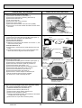
9-1. HOW TO CHECK THE PARTS
PLFY-P32/40/50/63/80/100/125VBM-E.UK
PLFY-P32/40/50/63/80/100/125VBM-ER2.UK
PLFY-P32/40/50/63/80VBM-E1.UK
PLFY-P32/40/50/63/80/100/125VBM-ER3.UK
Parts name
Check points
Room temperature
thermistor
(TH21)
Liquid pipe thermistor
(TH22)
Gas pipe thermistor
(TH23)
Disconnect the connector then measure the resistance with a tester.
(At the ambient temperature of 10 - 30)
Vane motor (MV)
Measure the resistance between the terminals with a tester.
(At the ambient temperature of 20 - 30)
White
MV
Orange
Red
Yellow
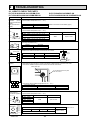
Blue
Drain pump (DP)
YLW
1
3
YLW
Drain float switch (FS)
Moving part
1
2
3
Normal
Abnormal
4.3k~9.6k
Open or short
Red - Yellow
Red - Blue
Red - Orange
Red - White
(Refer to Thermistor characteristic graph.)
Connector
(-, -, -, -)
(-
, -, -, -)
(-, -, -, -)
(-, -, -
, -)
Normal
Abnormal
300
Open or short
Measure the resistance between the terminals with a tester.
(Winding temperature 20)
Normal
290
Abnormal
Open or short
Measure the resistance between the terminals with a tester.
State of moving part
Normal
Abnormal
UP
Short
Other than short
DOWN
Open
Other than open
Switch
Magnet
4
i-see sensor
(Option)
Moving
Part
Turn on the indoor unit with the black plastic tape on the outside of i-see sensor controller board.
With electricity being turned on, measure the power voltage between connectors with tester.
i-see sensor rotates and pull out the connector of motor for i-see sensor.
Black plastic tape
Do not disassemble corner panel
with i-see sensor.
4 3 2 1
i-see sensor (At the ambient temperature of 10 - 40)
i-see sensor connector
4 3 2 1
Blue BlackPink Brown
(–)—(+)
Normal
DC 1.857V~ 3.132V
Abnormal
Other than the normal
(+)—(–)
DC 0.939V~ 1.506V
Other than the normal
NOTE : Be careful not to discharge static electricity into electronics.
Vane motor for
i-see sensor (Option)
White
MV
Orange
Red
Blue
Yellow
Linear expansion
Blue
valve(LEV)
M
Brown
Yellow
Measure the resistance between the terminals with a tester.
(At the ambient temperature of 20 - 30)
Connector
Red - Yellow
Red - Blue
Red - Orange
Red - White
Normal
Abnormal
250
Open or short
Disconnect the connector then measure the resistance valve with a tester.
Normal
White-Red
Abnormal
Yellow-Brown Orange-Red
200 $10%
White Red Orange
OCH413D
25
Blue-Brown
Open or short
Refer to 9-1-3.
9-1-1. Thermistor
<Thermistor characteristic graph>
Room temperature thermistor (TH21)
Liquid pipe temperature thermistor (TH22)
Gas pipe temperature thermistor (TH23)
Thermistor R0=15k' ± 3%
Fixed number of B=3480 ± 2%
Rt=15exp { 3480(
0:
10:
20:
25:
30:
40:
9-1-2.
1
273+t
40
Resistance (k)
Thermistor for
lower temperature
< Thermistor for lower temperature >
50
1
)}
273
30
20
10
15k'
9.6k'
6.3k'
5.4k'
4.3k'
3.0k'
0
-20
-10
0
10 20 30
Temperature ()
40
50
Linear expansion valve
1 Operation summary of the linear expansion valve
• Linear expansion valves open/close through the use of a stepping motor after receiving the pulse signal from the indoor
controller board.
• Valve position can be changed in proportion to the number of pulse signals.
<Connection between the indoor controller board and the linear expansion valve>
Controller board
DC12V
Brown
6
Blue
Red
5
Brown
Blue
4
:4
Yellow
Orange
3
:3
Yellow
2
:2
White
1
:1
Linear expansion valve
4
M
1
:4
6
:2
:1 5 :3 2
White Red
3
Orange
Connector(CN60)
OCH413D
26
Drive circuit
<Output pulse signal and the valve operation>
Output
Output
(Phase)
1
2
3
4
{1
ON
OFF
OFF
ON
{2
ON
ON
OFF
OFF
{3
OFF
ON
ON
OFF
{4
OFF
OFF
ON
ON
2 Linear expansion valve operation
Open
C
Valve position (capacity)
D
Close
Open
A
E
Close
Closing a valve : 1 → 2 → 3 → 4 → 1
Opening a valve : 4 → 3 → 2 → 1 → 4
The output pulse shifts in above order.
• When linear expansion valve operation stops, all output phase
become OFF.
• At phase interruption or when phase does not shift in order, motor
does not rotate smoothly and motor will lock and vibrate.
• When the switch is turned on, 2200 pulse closing valve signal will be
sent till it goes to point A in order to define the valve position.
When the valve moves smoothly, there is no sound or vibration
occurring from the linear expansion valves; however, when the pulse
number moves from E to A or when the valve is locked, more sound
can be heard than in a normal situation.
• Sound can be detected by placing the ear against the screw driver
handle while putting the screw driver tip to the linear expansion
valve.
Outdoor unit R410A model
: 1400 pulse
Outdoor unit R22/R407C model : 2000 pulse
Opening a valve
all the way
Pulse number
B
Extra tightening (200~800 pulse)
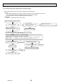
3 Troubleshooting
Symptom
Check points
Countermeasures
Operation circuit
failure of the micro
processor
Disconnect the connector on the controller board, then con- Exchange the indoor controller board at drive circuit
nect LED for checking.
6
5
failure.
4
3
2
1
1k LED
When power is turned on, pulse signals will be output for 10
seconds. There must be some defects in the operation circuit
if the LED does not light while the signals are output or keeps
lighting even after the signals stop.
Linear expansion
valve mechanism is
locked.
Exchange the linear expanMotor will idle and make a ticking noise when the motor is
operated while the linear expansion valve is locked. This tick- sion valve.
ing sound is the sign of the abnormality.
Short or breakage
Measure the resistance between each coil (white-red, yellow- Exchange the linear expanof the motor coil of
brown, orange-red, blue-brown) with a tester. It is normal if
sion valve.
the linear expansion the resistance is in the range of 200Ω ±10%.
valve
Valve does not close To check the linear expansion valve, operate the indoor unit If large amount of refrigercompletely.
in fan mode and at the same time operate other indoor units ant is leaked, exchange
the linear expansion valve.
in cooling mode, then check the pipe temperature <liquid
pipe temperature> of the indoor unit by the
outdoor multi controller board operation
monitor. During fan operation, linear expansion valve is closed completely and if there
Thermistor
(Liquid pipe) is any leaking, detecting temperature of
the thermistor will go lower. If the detected
Linear
temperature is much lower than the temexpansion
valve
perature indicated in the remote controller,
it means the valve is not closed all the way.
It is not necessary to exchange the linear expansion valve, if
the leakage is small and not affecting normal operation.
Wrong connection
of the connector or
contact failure
OCH413D
Check the color of lead wire and missing terminal of the con- Disconnect the connector
nector.
at the controller board,
then check the continuity.
27
9-1-3. DC Fan motor (fan motor/indoor controller board)
Check method of indoor fan motor (fan motor/indoor controller board)
Notes
· High voltage is applied to the connecter (CNMF) for the fan motor. Pay attention to the service.
· Do not pull out the connector (CNMF) for the motor with the power supply on.
(It causes trouble of the indoor controller board and fan motor)
Self check
Conditions : The indoor fan cannot turn around.
Indoor controller board fuse check
Is the fuse normal?
Is the resistance
between the terminals of
drain pump normal?
No
Yes
Replace the fan motor.
Replace the indoor controller board.
No
Wiring contact check
Contact of fan motor connector (CNMF)
Is there contact failure?
Yes
Replace the drain pump.
Yes
Wiring recovery
No
Power supply check (Remove the connector (CNMF))
Measure the voltage in the indoor controller circuit board.
TEST POINT : VDC (between 1 (+) and 4 (-) of the fan connector): VDC DC 310~340 V
TEST POINT : VCC (between 5 (+) and 4 (-) of the fan connector): VCC DC 15 V
Is the voltage normal?
Yes
Replace the fan motor.
No
Check the operation of fan.
Replace indoor
controller board
Check the operation
NG
OK
Replace indoor controller board.
END
NG
Replace the fan motor.
OCH413D
28
OK
END
9-2. FUNCTION OF DIP SWITCH
Switch Pole
SW1
Function
setting
OFF
Built-in remote controller
Indoor unit
2
Filter clogging detection
Provided
Not provided
3
Filter cleaning
2,500hr
100hr
4
Fresh air intake
Effective
Not effective
5
Switching remote
display
Indicating fan operation
Thermo ON signal display ON/OFF
6
Humidifier control
Always operated while the heat in ON +1 Operated depends on the condition *2
7
Low *3
Extra low *3
8
Airflow set in case of
thermo OFF
at heating mode
Setting air flow *3
Depends on SW1-7
9
Auto restart function
Effective
Not effective
Power ON/OFF by breaker
Effective
Not effective
P32
1~6
P40
P50
SW4
Model
Selection
(Setting
for
PLFY
series)
ON
Thermistor <Room temperature
detection> position
Capacity
SW3
Function
setting
Operation by switch
Function
1
10
SW2
Capacity
code
setting
The black square (■) indicates a switch position.
SW 2
ON
OFF
ON
OFF
ON
OFF
Capacity
SW 2
ON
OFF
P63
1 2 3 4 5 6
P125
1 2 3 4 5 6
ON
OFF
P80
1 2 3 4 5 6
1 2 3 4 5 6
ON
OFF
*3
1 2 3 4 5 6
Heat pump
2
Louver/humidifier +6
Available
Not available
3
Vane
Available
Not available
4
Vane swing function in heating
Available
(wave-flow)
Not available
5
Vane horizontal angle Second setting *4
First setting *4
6
Vane horizontal angle Third setting *4
Depends on SW3-5
7
Changing the opening of
linear expansion valve
Effective
Not effective
8
Sensible temperature correction Not effective
9
Superheat setting temperature *5
—
—
10
Sub cool setting temperature *5
—
—
Stop
Indoor controller board
Before
power
supply
ON
<Initial setting>
Set for each capacity.
Set while the unit is off.
ON
OFF
Under
suspension
Effective
When replacing the indoor controller board, make sure to set the switch to the
initial setting, which is shown below.
1 2 3 4 5
Before
power
supply
ON
<Initial setting>
1 2 3 4 5 6 7 8 9 10
Note :
*4 SW3-5, 6
*5 Please do not use SW3-9,
10 as trouble might be
caused by the usage
condition.
*6 SW3-2 setting
Only for PLFY-P·VBM, SW
is used to change whether
the humidifier functions or
not. (Fixed the louver
function less.)
Indoor controller board
Note : *4 SW3-5,6
OCH413D
Extra low
Low
Setting air flow
Indoor controller board
Cooling only
SW3-5
SW3-6
Vane setting
OFF
OFF
Set up ON
OFF
Set up OFF
ON
Set up ON
ON
unused
* Be careful of smudge on ceiling.
SW1-8
OFF
OFF
ON
ON
1 2 3 4 5 6
Heat pump/Cooling only
ON
OFF
SW1-7
OFF
ON
OFF
ON
Set while the unit is off.
1
1~5
1 2 3 4 5 6 7 8 9 10
Note :
*1 Fan operation at Heating
mode
*2 Thermo ON operation
Under
at Heating mode
suspension
SW 2
ON
OFF
Remarks
Address board
<Initial setting>
1 2 3 4 5 6
ON
OFF
P100
Capacity
Effective
timing
Initial setting Setting
Standard
Less draft *
Less smudging
—
●
29
Vane position
Standard
Upward position than the standard
Downward position than the standard
—
Switch Pole
SWA
Ceiling
height
selector
Effective
timing
Operation by switch
(High ceiling)
2
(Silent)
PLFY-P32·P40·P50·P63·P80VBM-E
SWA
1
SWB
4 direction
3 direction
2 direction
Silent
2.5m
2.7m
3.0m
SWB
4 direction
3 direction
2 direction
(2 direction) 2
3
(3 direction) 3
(4 direction) 4
Silent
2.7m
3.0m
3.3m
<Initial setting>
3
2
1
Standard
2.7m
3.0m
3.3m
High ceiling
3.5m
3.5m
3.5m
Standard
3.2m
3.6m
4.0m
High ceiling
4.5m
4.5m
4.5m
Address board
<Initial setting>
PLFY-P100·P125VBM-E
SWA
SWB
Discharge
outlet
number
selector
Address board
= Ceiling height can be changed depends on
SWB setting.
3
1~3 (Standard)
Remarks
Under
operation
or
suspension
2
3
4
Address board
SWC
Option
selector
2
When attaching the optional high performance
filter elements (multi function casement) to
the unit, be sure to attach it to in order to
prevent the airflow reducing.
<Initial setting>
30
78
78
Address board
<Initial setting>
SW14
F01
BCDE
BCDE
78
78
789A
Rotary switch
90 1
45 6
How to set branch numbers SW14 (Series R2 only)
Match the indoor unit’s refrigerant pipe with
the BC controller’s end connection number.
Remain other than series R2 at "0".
Before
power
supply
ON
SW11
23
Rotary switch
45 6
F01
90 1
789A
45 6
SW14
SW12
23
1
<Initial setting>
23
10
How to set addresses
Example : If address is "3", remain SW12
(for over 10) at "0", and match SW11 (for 1 to 9)
with "3".
45 6
90 1
45 6
OCH413D
SW11
23
90 1
45 6
SW12
23
SW14
Branch
No.
Setting
Address board
23
SW11
1s digit
address
setting
SW12
10ths digit
address
setting
J41, J42
Wireless
remote
controller
Pair No.
Jumper
Switch Pole
Operation by switch
• To operate each indoor unit by each remote controller when installed 2 indoor
units or more are near, Pair No. setting is necessary.
Pair No. setting is available with the 4 patterns (Setting patters A to D).
Make setting for J41, J42 of indoor controller board and the Pair No. of
wireless remote controller.
• You may not set it when operating it by 1 remote controller.
Setting for indoor unit
Jumper wire J41, J42 on the indoor controller board are cut according to
the table below.
Wireless remote controller pair number:
Setting operation
1. Press the SET button (using a pointed implement). Check that the
remote controller's display has stopped before continuing.
MODEL SELECT flashes, and the model No. (3 digits) appears (steadily-lit).
2. Press the MINUTE button twice. The pair number appears flashing.
3. Press the temperature
buttons to select the pair number to set.
4. Press the SET button (using a pointed implement). The set pair number is
displayed (steadily-lit) for 3 seconds, then disappears.
Setting pattern
Indoor controller
Jumper wire
Effective
timing
Remarks
<Initial setting>
Pattern A
Pair No.
MODEL SELECT
Under
operation
or
suspension
FAN
AUTO STOP
VANE
AUTO START
CHECK LOUVER
h
min
TEST RUN
SET
Temperature
button
TEMP
ON/OFF
MODE
Model No.
RESET
Minute
button
CLOCK
SET button
Pair No. of wireless
remote controller+
SWE
Test run
for
Drain
pump
Connector
J41
J42
A
—
—
0
Factory setting
B
Cut
—
1
—
C
—
Cut
2
—
D
Cut
Cut
3
—
+Pair No.4-9 of wireless remote controller is setting pattern D.
Drain pump and fan are activated simultaneously after the connector
SWE is set to ON and turn ON the power.
SWE
OFF
SWE
ON
OFF
ON
<Initial setting>
SWE
OFF
The connector SWE is set to OFF after test run.
OCH413D
Under
operation
31
ON
9-3. TEST POINT DIAGRAM
9-3-1. Indoor controller board
PLFY-P32/40/50/63/80/100/125VBM-E.UK
PLFY-P32/40/50/63/80/100/125VBM-ER2.UK
PLFY-P32/40/50/63/80VBM-E1.UK
PLFY-P32/40/50/63/80/100/125VBM-ER3.UK
CN6Y
CN60
i-See sensor motor output
12VDC pulse output
Linear expansion valve (LEV)
output
12VDC pulse output
CN3A
CN4Y
Connect to the terminal block (TB15)
(MA-Remote controller connecting wire)
1 - 3 : 8.7-13V DC (Pin1 (+))
i-See sensor
CN52
Remote indicator
1-2: Status lamp 12VDC (1 : +)
Fan motor output (SW1-5 OFF)
Thermostat ON (SW1-5 ON)
1-3: Cooling/Dry status lamp
12VDC (1 : +)
1-4: Heating status lamp
12VDC (1 : +)
CNV
vane motor output
12VDC pulse
CN32
Remote switch
CN51
Centrally control
1-2: Control signal
12VDC pulse input (1: +)
3-4: Operation indicator
12VDC (3: +)
3-5: Malfunction indicator
12VDC (3: +)
Jumper wire J41, J42
Pair No.setting for wireless
remote controller
LED2
Power supply for
MA-Remote controller
CN44
Pipe temperature thermistor
1-2 : Liquid (TH22)
3-4 : Gas (TH23)
SW3
Function setting
CN4F
SW4
CN20
SWE
Model selection
Drain float switch (FS)
Test run(Drain pump)
Room temperature
thermistor (TH21)
CN27
SW2
Damper signal output
12VDC(1 : +)
Capacity setting
CN3G
CN2M
Auto grille signal output
Connect to the terminal block (TB5)
(M-NET transmission connecting wire)
24-30VDC (non-polar)
CN90
Connect to the wireless
remote controller board
(W.B)
LED1
Main power supply
(Indoor unit : 220-240V)
CNMF
Connect to the
fan motor (MF)
1-4 : DC310~340V
5-4 : DC15V
CND
Power supply for indoor
controller board
3 - 5 : 220-240VAC
CNP
Drain pump output (DP)
1-3 : 220-240VAC
FUSE
6.3A 250V
CNAC
Auto grille power
(220-240VAC)
OCH413D
The voltage range of DC12V in this page
is between DC11.5 V to DC 13.7 V.
32
9-3-2. Address board
PLFY-P32/40/50/63/80/100/125VBM-E.UK
PLFY-P32/40/50/63/80/100/125VBM-ER2.UK
SWA
SW1
Ceiling height
selector
Function setting
SW12
Address setting
10ths digit
OCH413D
PLFY-P32/40/50/63/80VBM-E1.UK
PLFY-P32/40/50/63/80/100/125VBM-ER3.UK
SW11
Address setting
1s digit
SWC
SWB
Discharge outlet
number selector
Option selector
33
SW14
Branch No.
10
SPECIAL FUNCTION
10-1. HOW TO PERFORM THE UP/DOWN OPERATION OF THE AIR INTAKE GRILLE
10-1-1. Setting up the lowering distance of air intake grille
You can set up 8 different stages of lowering distance for
the air intake grille according to the set up location if desired.
Unit
Decorative
panel
* As a factory default, the decorative panel will automatically
stop at 1.6 m from the ceiling surface. The distance is a
rough indication, check by actually lowering it.
1) Take the cover off the electric box of the decorative panel. (2 screws)
2) Set up the dip switches of SW22 or SW2 on the control board of the
decorative panel as followed.
Cover for
Electric Box of
the decorative
panel
Control board of
the decorative
panel
SW 22 or SW2
Screws
Dip SW 22
Dip SW 2
The black square (■) indicates a switch position.
Lowering distance
SW22
(Rough indication
of the ceiling height) (Lowering distance)
The black square (■) indicates a switch position.
Lowering distance
SW22
(Rough indication
of the ceiling height) (Lowering distance)
Lowering distance
SW2
(Rough indication
of the ceiling height) (Lowering distance)
Lowering distance
SW2
(Rough indication
of the ceiling height) (Lowering distance)
Initial setting
Initial setting
1.2m
(~ 2.4m)
1.6m
(2.4m ~ 2.8m)
1.2m
(~ 2.4m)
1.6m
(2.4m ~ 2.8m)
2.0m
(2.8m ~ 3.2m)
2.4m
(3.2m ~ 3.6m)
2.0m
(2.8m ~ 3.2m)
2.4m
(3.2m ~ 3.6m)
2.8m
(3.6m ~ 4.0m)
3.2m
(4.0m ~ 4.4m)
2.8m
(3.6m ~ 4.0m)
3.2m
(4.0m ~ 4.4m)
3.6m
(4.4m ~ 4.8m)
4.0m
(4.8m ~ 5.2m)
3.6m
(4.4m ~ 4.8m)
4.0m
(4.8m ~ 5.2m)
* Airflow outreach distance is different depending on indoor units and
* Airflow outreach distance is different depending on indoor units
air volume (ceiling height), so airflow may not reach the indicated
ceiling height as shown in the above table.
and air volume (ceiling height), so airflow may not reach the
indicated ceiling height as shown in the above table.
3) Put the cover back on the electric box of the decorarive panel.
10-1-2. How to perform the up/down operation using wireless remote controller
Warning:
Ensure that the air-conditioner is not running.
• Otherwise, it may cause an injury or a failure.
1) Ensure that the air-conditioner is not running.
2) Press the "Down" button to lower the air intake grille.
* By default, the air intake grille will automatically stop at a lowering distance of 1.6 m from the ceiling level. The
distance can be changed to 1.2 m, 2.0 m, 2.4 m, 2.8 m, 3.2 m, 3.6 m and 4.0 m. These should be used only as
a guide. You should lower the air intake grille yourself to check the exact distance.
* When you want to stop the air intake grille while it is lowering, press the "Stop" or "Up" button on the remote
Wireless remote
controller to stop at that position.
controller for
3) Remove the filter or air intake grille and clean them.
Automatic Filter
4) Press the "Up" button on the remote controller to put the air intake grille in place.
Elevation Panel
* If the air intake grille is not placed in the correct position at a time, the operation is automatically retried.
* When you want to stop the air intake grille while it is rising, press the "Stop" or "Down" button on the remote controller to stop at
that position.
OCH413D
34
10-1-3. How to perform the up/down operation using wired remote controller (PAR-30MAA / PAR-31MAA)
1 Select "Maintenance" from the Main menu, and press the
button.
Select "Auto descending panel" with the F1 or F2 button, and press the
button.
Maintenance menu
Auto descending panel
Manual vane angle
Main menu:
Cursor
* When using the auto descending panel, always set the "Address" and "Unit
No." with "Service" – "Function setting".
F1
2 Move the cursor to "Ref. address", "Unit No." or "Operation" with the F1
button to select.
Select the refrigerant address and the unit number for the units to whose falls
panel, with the F2 or F3 button, and press the
button.
• Ref. address: Refrigerant address
• Unit No.: 1, 2, 3, 4, All
• Operation: Down / Up
F2
F3
F4
Auto descending panel
Ref. address
Unit No.
All
Operation
Down / Up
Keep clear, panel descending.
Press Check for Unit No.
Input display:
Cur.
Address
Check
F1
F2
F3
F4
Press the F4 button to confirm the unit.
<Confirmation of target unit>
If the unit being set is unknown, make the setting and then press the F4 button to conf rm.
The air conditioner which is blowing downward is the target air conditioner.
Navigating through the screens
• To go back to the Main menu ..................
button
• To return to the previous screen ...............
button
OCH413D
Auto descending panel
Ref. address
Unit No.
All
Operation
Down / Up
Panel will stop in 30 sec.
Keep clear, panel descending.
Cur.
Address
Check
F1
35
F2
F3
F4
10-1-4. How to perform the up/down operation using wired remote controller (PAR-21MAA)
N General Operation
* Raise or lower all the air intake grilles managed by the remote controller at the same time.
Install the remote controller in a place where you can observe all the air-conditioners. Otherwise, the lowering grille may make
contact with something and cause damage to it.
1) Ensure that the air-conditioner is not running.
* The up/down operation mode is only available when the
air-conditioner is "OFF".
Warning:
Ensure that the air-conditioner is not running.
• Otherwise, it may cause an injury or a failure.
2) Press both the "FILTER" and "Ventilation" buttons simultaneously for 2 seconds or more to enter the up/down
operation mode.
"Up/down operation
mode" display
3) Press the TEMP. ( ) button. After a while, the air intake grille will begin lowering.
"Stand by for lowering"
display
[ Note: ]
Alternately
• You cannot stop the operation while the air intake grille is lowering.
* If you press the ( ) button while the air intake grille is moving down, the air intake grille may
stop lowering, but it will not stop immediately.
• By default, the air intake grille will automatically stop at the lowering distance of 1.6 m
from the ceiling level.
* The distance can be changed to 1.2 m, 2.0 m, 2.4 m, 2.8 m, 3.2 m, 3.6 m, and 4.0 m.
These should be used only as a guide. You should lower the air intake grille yourself
to check the exact distance.
"Lowering" display
(blinking)
"Stopped" display
(when finished lowering)
4) Remove the filter and/or air intake grille to clean them.
5) Press the TEMP. ( ) button. After a while, the air intake grille will begin to rise and then be put back into place.
"Stand by for raising" display
Alternately
[ Note: ]
"Raising" display (blinking)
• You cannot stop the operation while the air intake grille is rising.
* If you press the ( ) button while the air intake grille is moving up,
the air intake grille maystop rising, but it will not stop immediately.
"Stopped" display (when the air intake
grille has been put back into place)
6) Exit the up/down mode either by pressing the "ON/OFF" button or by pressing both the "FILTER" and "Ventilation"
buttons simultaneously for 2 seconds or more.
* After exiting the up/down mode, wait for
about 30 seconds to perform the next
Operation status
operation. The remote controller will not
display
accept any operation for that period.
Button to exit the up/down
operation mode
Down/Up
buttons
TEMP.
MENU
BACK
PAR-21MAA
OCH413D
36
MONITOR/SET
ON/OFF
ON/OFF
FILTER
DAY
CLOCK
CHECK TEST
OPERATION
CLEAR
Buttons to enter the up/down
operation mode (Press them
simultaneously for 2 seconds.)
■ Up/down operation with the individual specified air-conditioner (when used in combination with Mr. SLIM model)
* Raise or lower the air intake grille of the specific air-conditioner that you select from all that are managed by that remote controller.
1) Ensure that the air-conditioner is not running.
Ensure that the air-conditioner is not running.
Warning:
* The up/down operation mode is only available when the
• Otherwise, it may cause an injury or a failure.
air-conditioner is "OFF".
2) Press both the "FILTER" and "Ventilation" buttons simultaneously for 2 seconds or more to enter the up/down
operation mode.
Up/down operation mode
3) Press the "Ventilation" button. After a while, it will switch to the "individually-specified up/down operation
mode".
Up/down operation mode
Individually-specified up/down operation mode
Refrigerant address No.
Unit No.
If the number of the target airconditioner is unknown, go to 4).
In the upper right figure, the air-conditioner
which the refrigerant address is "00" and
the unit No. is "1" is currently selected.
If the number of the target airconditioner is known, go to 5).
4) If you press the "FILTER" button when the "Unit No." or "Refrigerant address No." is blinking,
the up/down airflow direction of the displayed air-conditioner will be switched downward after a while,
and the airflow direction of the other vents will all be blocked.
■ In Step 5) described below, identify the target
[Remarks:]
■ If "Err" is displayed when you press the "FILTER" button to check the target
air-conditioner by changing the "Unit No." and
air-conditioner, the air-conditioner with that "Unit No." or "Refrigerant
"Refrigerant address No." and by pressing the "FILTER"
address" may not exist. Check and set that air-conditioner again.
button to check the up/down airflow direction.
5) Select the "Unit No." and "Refrigerant address No.".
■ "Unit No." and "Refrigerant address No." can be changed by using the "TEMP." buttons ( ) ( ) when the panel
displays (a) or (b).
■ Every time you press the "Mode selection" button, the target of operation will change as illustrated below.
(a) "Unit No." selection
display
(c) "Standby for up/down operation" display
[Remarks:]
■ Each pressing action changes the unit No. from "1 - 4" to "0".
(Unit No. "0" means that all of 1 - 4 are targeted.)
■ Each press changes the "Refrigerant address" from "0 to 15".
(b) "Refrigerant address No." selection display
6) Continue to press the "Mode selection" button until "Waiting for up/down operation" is displayed.
"Waiting for up/down operation" display
The following steps are the same as steps 3) - 6) described in the "General Operation" section. Refer to that
section.
Operation status display
Down/Up buttons (for selecting
unit No. and refrigerant
address)
Mode selection
Button to exit the up/down
operation mode
TEMP.
MENU
BACK
PAR-21MAA
OCH413D
MONITOR/SET
ON/OFF
ON/OFF
FILTER
DAY
CHECK TEST
OPERATION
CLOCK
37
CLEAR
Buttons to enter the up/down
operation mode (Hold them
down simultaneously for 2
seconds.)
10-2. OPERATION (AUTO DESCENDING PANEL: PLP-6BAJ)
(1) Normal operation
UP/DOWN
Wire 1b
Air intake grille is raised/lowered by
UP/DOWN
UP/DOWN
commands of UP and DOWN.
Machine 2
Machine 1
Air intake grille does not move under the
state of no-load detection or obstacle detection.
Air intake grille stops automatically at the set lowering
distance from the ceiling level.
Detection
STOP
Wire 2b
switch
Wire 2a
It stops in the cases below :
• When it reaches at the set lowering distance from
the ceiling level.
It automatically stops after a predetermined period
Wire 1a
of lowering.
Fig.1
• When it is stored in the panel.
The air intake grille is judged to be stored in the panel
when the storage detection switch is pressed for 3 seconds continuously.
• When receiving commands of STOP, DOWN while moving up or UP while moving down.
The STOP button is only available on the automatic filter elevation panel remote controller.
When the wired remote controller is used, there will be a slight delay in stopping due to transmission speed.
• When both wire 1b and wire 2b are not loaded.
Only the wire b in each UP/DOWN Machine has a tension detection switch.
(2) Special operation
Storage operation
Case : Obstruction of the raising grille before storage or malfunction of storage detection switch
Storage operation will be performed when the intake grille has been raised the set distance but the
storage detection switch is not engaged.
In this case, the operation below will be repeated up to 4 times.
10 cm down 30 cm up
···· 10 cm down 30 cm up
No-load detection
Case : UP/DOWN commands with no grille suspended.
When both wire 1b and wire 2b are not loaded, the wires will not move.
Obstacle detection
Case : Making contact with something while lowering.
Should the loads on the wire 1b and wire 2b be removed due to the grille making contact with something while lowering,
the lowering operation will stop. The grille will then be raised 10 cm and stop again.
[Emergency operation]
• When the wireless remote controller cannot be used (in the case of battery discharge, misplacing of the wireless
remote controller, malfunctioning and so on), the emergency switch on the receiver can be used as an alternative.
* When doing this, particular caution must be taken not to fall.
To lower the air intake grille : Press the
button once.
(For emergency heating operation, press and hold this button.)
To raise the air intake grille : Press the
button once.
(For emergency cooling operation, press and hold this button.)
• To stop the air intake grille from moving, use the opposite buttons to those used to initiate movement.
(To stop it from lowering, press the UP button; To stop it from rising, press the Down button.)
• If up/down machine is out of order, fix air intake grille temporarily and the indoor unit can be operated.
* For details, refer to installation manual for the attachment of grille.
OCH413D
38
10-3. ELECTRICAL CIRCUIT (Controller board and wiring diagram (Panel))
10-3-1. Dip SW 22 type
SW22
LS1
BLK
BLK
UK1
LS21
2
1
WHT
WHT
Panel
B O Y
R R L
N N W
CN3G
1 2
W.B
BZ
SW1
FUSE
CN2F
(BLK)
RU
CN2E
(RED)
2 WHT
1 WHT
CN2C
CN2B
(WHT)
(WHT)
1 2
MU1
ON
SW2
1 2
1 2
LS21
SW22
1 2 3 4 5 6 7 8 9 10
CNB
(WHT)
3 2 1
(BLK)
CN2G
(BLK)
MU1
UK1
Indoor unit
3
B R
L E
K D
9
I.B
CN90
(WHT)
CNAC
(WHT)
CN22
(BLU)
CN3G
(BLK)
GRN/YLW
R R B
E E L
1 2
1
2
3
4
5
6
7
8
9
CN3A D D K
B R
L E
K D
(RED)
5 3 1
TB5
Symbol
U.B
Name
Auto grille controller board
Fuse (3.15A)
SW22
Switch (Lowering distance set up)
Up/down machine
Motor (Up/down)
Limit switch (tension detection)
UK1
MU1
LS21
I.B
SYMBOL
FUSE
SW1
SW2
SW3
LS1
R.B
1
2
R.B
Name
Wireless remote controller board
Buzzer
Receiver
Emergency switch (heating/down)
Emergency switch (cooling/up)
Limit switch (storage detection)
Wired remote controller
SW2
NAME
CONTROLLER BOARD
FUSE (T3.15AL250V)
SWITCH (MODEL SELECTION)
SWITCH (LOWERING DISTANCE)
SWITCH (SYSTEM SELECTION)
LED1
LED RED
(MICROCOMPUTER POWER)
LED2
LED RED
(GRILLE CONDITION)
OCH413D
BZ
RU
SW1
SW2
TB6
Indoor controller board
10-3-2. Dip SW 2 type
U.B
Symbol
W.B
FUSE
1
2
U.B
I.B
W.B
SYMBOL
BZ
RU
SW1
SW2
NAME
SYMBOL
INDOOR UNIT CONTROLLER BOARD UK1
M
WIRELESS SIGNAL RECEIVER BOARD
LS21
BUZZER
LS1
RECEIVING UNIT
R.B.
EMERGENCY HEATING
GRILLE / DOWN
LONG PRESS FOR OVER 2 SEC) (SHORT PRESS)
EMERGENCY COOLING
GRILLE / UP
LONG PRESS FOR OVER 2 SEC) (SHORT PRESS)
39
NAME
UP/DOWN MACHINE
MOTOR (FOR GRILLE UP/DOWN)
LIMIT SWITCH (TENSION DETECTION)
LIMIT SWITCH (STORAGE DETECTION)
WIRED REMOTE CONTROLLER
10-3-3. Check point of trouble
<LED (SW22 type) /LED2 (SW2 type) display>
Turn OFF
: No power supply
Blink
: Storage detection switch ON (short)
One blink
: Storage detection switch OFF (open)
Two blinks
: Tension detection switch OFF (open)
<controller board>
Check item
Up/down controller
P.C. board supply
voltage
Up/down machine
supply voltage
Check point
Normal
Remarks
CN3A
(between 3-5)
AC 198~264 V
CN2B, CN2C
DC 10~12 V
Check when instructing up/down with LED
blinking once.
Check point
Normal
Check contents
CN2E
open or short
Check if it is short when pressing push switch.
<Up/down machine>
Check item
Storage detection
switch
Tension detection
switch
Motor
CN2F, CN2G
open or short
Check if it is short when wire b is tensioned.
CN2B, CN2C
Check if it is not open or short.
Entwining wires
Pull wire
5~20 Retension:
about 2 kgf
Check if wire is drawn out by pulling with 3 kgf.
10-4. TROUBLESHOOTING
• Check the following points.
Problem
Possible Reason
Corrective Action
Air-conditioner is running.
Stop running the air-conditioner and try again.
Power failure
After recovering from power failure, try again.
Batteries are not inserted into the wireless remote controller.
Or battery power is running low.
Insert or replace the battery.
There is something on the air intake grille.
Or something is stuck in the air intake grille.
Remove the objects or obstacles from the
air intake grille.
Or, remove the stuck object.
There is something on the air intake grille.
Remove the objects or obstacles from the
air intake grille.
Filter is not properly installed.
Lower the air intake grille again and check
whether the filter is installed in the correct
position.
Air intake grille is not hung with all 4 hooks.
Lower the air intake grille again and hook
on the air intake grille.
Air intake grille stops lowering.
(Air intake grille would not
lower any further.)
The air intake grille has finished lowering to the auto-stop
position.
This is normal.
Noises are made during
up/down operation.
(While air intake grille is
moving up/down.)
This is the noise made when the wire is wound and
unwound.
Noises are made while putting
the air intake grille into place.
This is the operational noise for putting the air intake
grille into place.
Air intake grille repeats rising
and lowering several times
while being put into place.
This is the operation for putting the air intake grille into
place.
Air intake grille leans toward
one side during the up/down
operation.
The speeds of winding/unwinding wires are slightly
different for each wire.
Air intake grille does not
function with operation of the
wireless remote controller.
Air intake grille cannot be
fixed in place.
OCH413D
40
This is normal.
11
DISASSEMBLY PROCEDURE
PLFY-P32/40/50/63/80/100/125VBM-E.UK
PLFY-P32/40/50/63/80VBM-E1.UK
PLFY-P32/40/50/63/80/100/125VBM-ER2.UK
PLFY-P32/40/50/63/80/100/125VBM-ER3.UK
Be careful when removing heavy parts.
OPERATING PROCEDURE
PHOTOS & ILLUSTRATIONS
1. Removing the air intake grille
(1) Slide the knob of air intake grille toward the arrow 1 to
open the air intake grille.
(2) Remove drop prevention hook from the panel.
(3) Slide the shaft in the hinge to the direction of the arrow 2
and remove the air intake grille.
Figure 1
2. Removing the room temperature thermistor (TH21)
(1) Remove the air intake grille and the filter. (See Figure 1)
(2) Remove the 2 screws from the electrical box cover.
(3) Disconnect the connector CN20 (Red) from the indoor controller board.
(4) Remove the room temperature thermistor.
Photo 1
3. Removing the address board (A.B)
(1) Remove the air intake grille and the filter. (See Figure 1)
(2) Remove the 2 screws from the address board cover.
(3) Disconnect the connectors CN43 (RED/4P) and CN82
(RED/8P).
(4) Slide and remove the address board.
4. Removing the indoor controller board (I.B)
(1) Remove the air intake grille and the filter. (See Figure 1)
(2) Remove the 2 screws from the electrical box cover.
(3) Disconnect the connectors :
CNMF
(White/7P) for fan motor
CN44
(White/4P) for thermistor (TH22/TH23)
CNP
(Blue/3P) for drain pump
CN4F
(White/4P) for float switch
CN01
(Black/5P) for earth and TB2
CNV
(White/20P) for vane motor
CN81, CN42 (Red/8P,4P) for address board
CN2M
(Blue/2P) for TB5
(4) Remove the 6 supports from indoor controller board.
(5) Remove the indoor controller board.
5. Removing the electrical box
(1) Remove the air intake grille and the filter. (See Figure 1)
(2) Remove the 3 screws from the electrical box cover.
(3) Disconnect the connectors. (Refer to procedure 4)
(4) Remove 4 electrical box fixing screws and remove 2 hooks.
(5) Pull the electrical box.
<Electrical parts in the electrical box>
Indoor controller board
Terminal block (TB2) (TB5)
OCH413D
41
Filter
Address board
cover fixing
screw
MA remote
controller
terminal
cover
Terminal
cover fixing
screw
Address
board
Address
board cover
fixing screw
Electrical box cover
fixing screws
Photo 2
Electrical box cover
Bell mouth
Room temp.
thermistor
(TH22)
Turbo fan
Electrical
box fixing
screws
Nut
Electrical
box fixing
screws
Electrical box
Indoor controller
board
Support for Indoor
controller board
OPERATING PROCEDURE
PHOTOS & ILLUSTRATIONS
Coil plate
Photo 3
6. Removing the fan and fan motor (MF)
(1) Remove the electrical box. (See Photo 2)
(2) Remove the bell mouth (3 screws). (See Photo 2)
(3) Remove the turbo fan nut.
(4) Pull out the turbo fan.
(5) Remove the wire cover (3 screws).
(6) Remove 2 wiring clamps.
(7) Disconnect the connector of the fan motor (CNMF).
(8) Remove the 3 nuts and washers and rubber mounts of the
fan motor.
Fan motor
Clamp
Wire cover
fixing screws
Nut,
Washer,
Rubber mount
Figure 2
7. Removing the panel
(1) Remove the air intake grille and the filter. (See Figure 1)
(2) Disconnect the connector CNV (White/20P).
Corner panel (See Figure 2)
(3) Remove the corner screw.
(4) Slide the corner panel to the direction of the arrow 1, and
remove the corner panel.
Panel (See Photos 4, 5)
(5) Remove the 2 screws from the panel which fix to the oval
holes.
(6) Rotate the panel a little to come to the bell shaped hole
where the screw is large and remove the panel.
Screw
Detail Screw Corner panel
Corner panel
Photo 4
Ball shaped hole
Panel
Photo 5
Oval hole
Photo 6
8. Removing the drain pan
(1) Remove the air intake grille and the filter. (See Figure 1)
(2) Remove the 2 screws from the electrical box cover.
(3) Disconnect the connectors. (Refer to procedure 4)
(4) Remove the panel. (See Photos 4, 5)
(5) Remove the electrical wiring service panel (3 screws).
(6) Remove the drain pump wire cover (1 screw).
(7) Remove the electrical box. (See Photo 2)
(8) Remove the bell mouth. (See Photo 2)
(9) Remove the 4 screws and pull out the drain pan.
* Pull out the left and right of the pan gradually.
Be careful not to crack or damage the pan.
Drain pump wire cover
Drain pan
fixing screw
Drain pan
fixing screws
Electrical wiring
service panel
Drain pan
fixing screw
Electrical wiring service
panel fixing screws
9. Removing the liquid pipe temperature thermistor (TH22)
and gas pipe temperature thermistor (TH23)
(1) Remove the drain pan. (See Photo 6)
(2) Remove the turbo fan. (See Photo 3)
(3) Remove the 2 wiring clamps. (See Photo 3)
(4) Remove the coil plate (2 screws).
(5) Remove the thermistors which are inserted into the holders
installed to the thin copper pipe.
(6) Disconnect the 4-pin white connector (CN44).
Photo 7
Drain pan
Gas pipe temp. thermistor (TH23)
Liquid pipe temp. thermistor (TH22)
OCH413D
42
OPERATING PROCEDURE
PHOTOS & ILLUSTRATIONS
10 Removing the drain pump (DP) and float switch (FS)
(1) Remove the drain pan. (See Photo 6)
(2) Cut the hose band and remove the hose.
(3) Remove the drain pump assembly (3 screws and 2 hooks).
(4) Remove the drain pump (3 screws).
(5) Remove the float switch (2 screws).
Photo 8
Float switch
Hose band
Drain pump
Drain pump assembly
fixing screws
Photo 9
Drain pump
fixing screws
11. Removing the heat exchanger
(1) Remove the drain pan. (See Photo 6)
(2) Remove the 3 screws of the piping cover, and pull out
piping cover.
(3) Remove the 2 screws of coil plate.
(4) Remove the 2 screws of the coil.
(5) Remove the screw of the coil support.
(6) Pull out the heat exchanger.
Photo 10
Heat exchanger
43
Linear expansion
valve
Piping cover
Heat exchanger
fixing screws
Coil support
OCH413D
Float switch
fixing screws
HEAD OFFICE : TOKYO BLDG., 2-7-3, MARUNOUCHI, CHIYODA-KU TOKYO 100-8310, JAPAN
cCopyright 2007 MITSUBISHI ELECTRIC CORPORATION
Distributed in Dec. 2012 No. OCH413 REVISED EDITION-D
Distributed in Aug. 2009 No. OCH413 REVISED EDITION-C PDF 6
Distributed in Feb. 2009 No. OCH413 REVISED EDITION-B PDF 6
Distributed in Oct. 2007 No. OCH413 REVISED EDITION-A PDF 7
Distributed in Mar. 2007 No. OCH413 PDF 7
Made in Japan
New publication, effective Dec. 2012
Specifications are subject to change without notice.