1
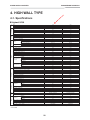
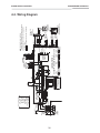
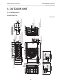
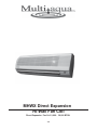
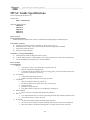
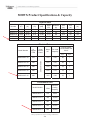
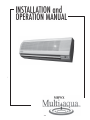
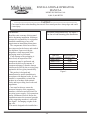
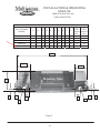
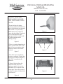
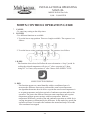
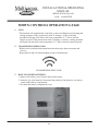
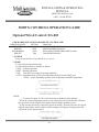
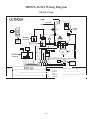
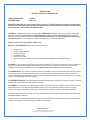
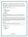
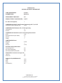
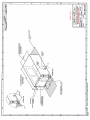
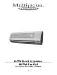
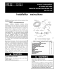
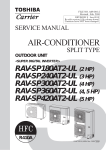
TRANSMITTAL
5995 Greenwood Plaza Blvd.
Suite 100
Greenwood Village, CO 80111-4710
303-571-5377
303-629-7467 (fax)
PROJECT:
TO:
ATTN:
Ph/Fax:
No. 12J2000-0141
DATE: 12/19/2012
Northwestern Mutual-West Denver Office Bldg
Adams County Plumbing & Heating Co
2669 E Hwy 224
Denver CO 80229
RE:
238126-Split-System Air-Conditione
Tamara Carhart
303-288-4546
JOB:
303-289-5756
WE ARE SENDING:
SUBMITTED FOR:
12J2000
ACTION TAKEN:
Shop Drawings
Approval
Approved as Submitted
Letter
Your Use
Approved as Noted
Prints
As Requested
Returned After Loan
Change Order
Review and Comment
Resubmit
Submit
Plans
SENT VIA:
Samples
Returned
Specifications / Product Data
Attached
Returned for Corrections
Other:
Separate Cover Via:
Due Date: 12/18/2012
NOTES:
Item
Package
Code
Submittal
238126
238126.01
1
1
12/19/2012
Submittal
238126
238126.02
1
1
12/19/2012
Submittal
238126
238126.03
1
1
12/19/2012
Submittal
238126
238126.04
1
1
12/19/2012
Submittal
238126
238126.05
1
1
12/19/2012
Submittal
238126
238126.06
1
1
12/19/2012
Submittal
238126
238126.07
1
1
12/19/2012
Submittal
238126
238126.08
1
1
12/19/2012
Rev. Copies Date
Description
Status
Split-System Air-Conditioners- FCU-1Fan Coil Unit- Product Data
Split-Split-System Air-ConditionersFCU-1- Fan Coil Unit- Shop Drawings
Split-Split-System Air-ConditionersFCU-2- Fan Coil Unit- Product Data
Split-Split-System Air-ConditionersFCU-2- Fan Coil Unit- Shop Drawings
Split-System Air-Conditioners- ACCU1- Air Cooled Condensing Unit- Product
Data
Split-System Air-Conditioners- ACCU1- Air Cooled Condensing Unit- Shop
Drawings
Split-System Air-Conditioners- ACCU2- Air Cooled Condensing Unit- Product
Data
Split-System Air-Conditioners- ACCU2-Air Cooled Condensing Unit- Shop
Drawings
No Exceptions
Taken
No Exceptions
Taken
No Exceptions
Taken
No Exceptions
Taken
No Exceptions
Taken
CC:
Signed:
Jennifer Lynn
No Exceptions
Taken
No Exceptions
Taken
No Exceptions
Taken
3025 S. Parker Rd | Suite 1100 | Aurora | CO | 80014
(303)696-2602 | www.ssgroupinc.com
SSG MEP, Inc.
Date Received:
December 4, 2012
☒ REVIEWED
☐ REJECTED
☐ REVISE & RESUBMIT
Submittal Number:
238126
Project Name:
Northwestern Mutual-West Denver
Office Building
Project Number:
12J2000
Client/Construction Manager:
Barker Rinker Seacat & Partners
☐ FURNISH WITH CHANGES NOTED
☐ RESUBMIT SPECIFIC ITEM(S)
☐ TRANSMITTED WITH NO REVIEW MADE
Actions taken by SSG MEP, Inc. with respect to the Submittal are only for general
conformance with the design concepts of the Project based upon the Contract
Documents. In all respects, SSG MEP, Inc. is subject to the terms and conditions of its
contract with its Client. Notations, “corrections” or comments on the Submittal(s) do
not modify the obligations of the contractor or its subcontractors from those set forth in
the Contract Documents. Contractor shall field verify, confirm, correlate all dimensions,
sizes and tolerances before construction or installation of any component or assembly
begins. Unless otherwise specifically noted on the submittal, all fabrication, installation and
construction means, methods, techniques, sequences, schedules and procedures remain
solely the responsibility of the contractor. Contractor remains solely responsible for job
site safety and all safety precautions and procedures. Notwithstanding anything else to the
contrary, SSG MEP, Inc. by reviewing this Submittal does not assume professional
responsibility for any design or work product (including but not limited to its technical
accuracy or professional competency) provided by contractor or owner on a “design
build” or “performance specification” basis. SSG MEP, Inc. provides no warranties,
expressed or implied.
Reviewed By: AEI
SSG MEP, Inc. Project Number: 10054.00
Date: December 17, 2012
Submitting Contractor:
GHPhipps
Description:
Split System Air Conditioners
A – No Exceptions Taken
C – Rejected
B – Make Correction(s) as Noted, No Resubmittal Required
D – Revise and Resubmit
E – Submit Specified Item
ITEM
REFERENCE
(e.g. spec #
(e.g. page # or paragraph)
COMMENTS
ACTION
(legend above)
or dwg #)
238126 –
Split System Air
Conditioners
238126 –
Split System Air
Conditioners
FCU-1/ACCU-1
Carrier
No comment.
A
FCU-2 Multi-aqua/ACCU-2
Compu-Aire, Inc.
No comment.
A
O:\Data A-F\Barker Rinker Seacat (BRS)\Northwestern Mutual West Denver Office Building\construction
admin\submittals\Mechanical\2012.12.17 NW Denver - Submittal Review Form - Split Systems.docx
Page 1 of 1
TRANSMITTAL
5995 Greenwood Plaza Blvd.
Suite 100
Greenwood Village, CO 80111-4710
303-571-5377
303-629-7467 (fax)
PROJECT:
TO:
ATTN:
Ph/Fax:
No. 12J2000-0103
DATE: 12/04/2012
Northwestern Mutual-West Denver Office Bldg
Barker Rinker Seacat & Partnrs
3457 Ringsby Ct #200
Denver CO 80216
RE:
238126-Split-System Air-Conditione
Keith Hayes
JOB:
303-455-1366
WE ARE SENDING:
SUBMITTED FOR:
12J2000
ACTION TAKEN:
Shop Drawings
Approval
Approved as Submitted
Letter
Your Use
Approved as Noted
Prints
As Requested
Returned After Loan
Change Order
Review and Comment
Resubmit
Submit
Plans
SENT VIA:
Samples
Returned
Specifications / Product Data
Attached
Returned for Corrections
Other:
Separate Cover Via:
Due Date: 12/11/2012
NOTES:
Item
Package
Code
Submittal
238126
238126.01
1
1
12/04/2012
Submittal
238126
238126.02
1
1
12/04/2012
Submittal
238126
238126.03
1
1
12/04/2012
Submittal
238126
238126.04
1
1
12/04/2012
Submittal
238126
238126.05
1
1
12/04/2012
Submittal
238126
238126.06
1
1
12/04/2012
Submittal
238126
238126.07
1
1
12/04/2012
Submittal
238126
238126.08
1
1
12/04/2012
Rev. Copies Date
Description
Status
Split-System Air-Conditioners- FCU-1Fan Coil Unit- Product Data
Split-Split-System Air-ConditionersFCU-1- Fan Coil Unit- Shop Drawings
Split-Split-System Air-ConditionersFCU-2- Fan Coil Unit- Product Data
Split-Split-System Air-ConditionersFCU-2- Fan Coil Unit- Shop Drawings
Split-System Air-Conditioners- ACCU1- Air Cooled Condensing Unit- Product
Data
Split-System Air-Conditioners- ACCU1- Air Cooled Condensing Unit- Shop
Drawings
Split-System Air-Conditioners- ACCU2- Air Cooled Condensing Unit- Product
Data
Split-System Air-Conditioners- ACCU2-Air Cooled Condensing Unit- Shop
Drawings
Architect Review
CC:
Signed:
Jennifer Lynn
Architect Review
Architect Review
Architect Review
Architect Review
Architect Review
Architect Review
Architect Review
Submittal Stamp Sheet
Project: Northwestern Mutual West Denver Office Bldg
Project Address: 825 Simms Street, Lakewood CO
Phipps’ Job #: 12J2000
Subcontractor / Supplier
Specification Section
Submittal No.
Submitted For:
Barker Rinker Seacat Architecture
3457 Ringsby Court, Suite 200
Denver CO 80216
Adams County Plumbing & Heating
238126 Split System Air Conditioners
238126.01, 02, 05, 06: FCU/ACCU-1 Product Data & Shop Drawings
APPROVAL
Gerald H. Phipps, Inc.:
RESUBMITTAL
Architect:
SUBMITTED
GH Phipps
Construction Companies
GH Phipps has reviewed, approved, and herby submits the
attached in accordance with the contract documents.
Note to Subcontractor/Material Supplier:
Subcontractor/Material Supplier remains responsible for the
confirmation and correlation of dimensions at the jobsite;
fabrication processes and construction techniques; coordination
of the work with the work of other trades; and satisfactory
performance of the work.
DATE: 11/30/12
Jennifer Lynn, Project Engineer
Engineer:
NOTES:
Other:
RECORD ONLY
Carrier West
4800 Osage Street
Denver, CO 80221
Ph: (303) 825-4328
Fax: (303) 820-2302
_______________________________________________________________________________________________
RE-SUBMITTAL COVER SHEET
Northwestern Mutual
Denver, Colorado
Adams County Heating and Plumbing
JOB:
LOCATION:
CONTRACTOR:
TAG
RTU-1
QTY
1
MODEL NUMBER
48A5T035FQV62AER
FCU/ACCU-1
1
RAV-SP180KRT-UL
RAV-SP180AT2-UL
FCU/ACCU-2
1
MHWX-36-H-1
MKA-212
VAV
21
35ED
DESCRIPTION
Carrier 35 Ton R410A Variable Air Volume
Packaged Gas Heating / Electric Cooling
Rooftop Unit 460 Volt – 3 Phase – 60 Hertz
1.5 Ton High Wall Duct Free Fan Coil with
1.5 Ton Remote Outdoor Condensing Unit
208/230 Volt – 1 Phase – 60 Hertz
2.5 Ton High Wall Duct Free Fan Coil with
2.5 Ton Ducted Indoor Condenser
208/230 Volt – 1 Phase – 60 Hertz
Carrier Pinch-Off Variable Air Volume Boxes
with BACnet Controls
CARRIER WEST CERTIFIED THE ABOVE DATA TO BE A TRUE ABSTRACT OF
MANUFACTURES’ CURRENT RATINGS FOR THE PRODUCTS SHOWN.
DATE:
October 2, 2012
PREPARED BY: Corey W. Trease
2669 E. Hwy 224•Denver, CO 80229•303 288 4546•FAX: 303 289 5756
DATE: November 9, 2012
JOB NO:
PROJECT:
GENERAL
CONTRACTOR:
ARCHITECT:
MECH. ENGINEER:
SUPPLIER:
12 129
Northwestern Mutual West Denver Office
Building
GH Phipps
Barker Rinker Seacat Architecture
Scanlon Szynskie Group
Carrier
SUBMITTAL NO:
01
SPECIFICATION:
237413 – Packaged, Outdoor, Central
Station Air Handling Units
All Required Sections (RTU 1)
PARAGRAPH:
Quality Workmanship Since 1965
SUBMITTAL
Performance Data
Certified Dimension Print
Model: RAV-SP180KRT-UL
RAV-SP180AT2-UL
208/230 Volt – 1 Phase – 60 Hertz
Qty: 1
Tagged: FCU/ACCU-1
Includes: Condensate Pump, Condensing Unit Pad, Low Ambient Standard to 5 Degrees
(Wind Baffle Field Fabricated)
Date: June 14, 2012
2.0"(50)
5.2"(132)
Knock out system
12.6"(320)
Air inlet
Connecting pipe 13.4"(0.34m)
1/2"(12.7mm)
22.4"(568)
Knock out system
2.0"(50)
9.0"(228)
5.9"(150)
1.9"(47)
2.9"(73.5)
2.9"(73.5)
A
B
C
Distance
0.9"
(24)
8.5"(215)
Center line
10.3"(262.5)
Hanger
3.2"
(82)
0.9"(26)
Instrallation plate outline
6.0"
4.3"
(153.5) (109)
0.9"
(23)
5.2"(132)
Remote controller holder
10.3"(262.5)
Hanger
8.5"(215)
30.9"(786)
9.3"(235)
9.3"(235)
Hanger
Comments
C
2.0"(50) or more
33.5"(850) or more For exchange of cross flow fan
6.7"(170) or more
B
A
Space required for installation and servicing
Wireless remote controller
2.2"
(56)
8.5"(215.5)
3.3"
(85)
5.2"(132)
0.3"(7)
CAUTION
Connecting pipe cannot be connected to the
right side of the indoor unit when conduit pipe
is used.
When connecting pipe is connected on the
left or bottom of the indoor unit, connect the
conduit pipe on other side.
Connecting pipe 12.3"(0.49m)
1/4"(6.35mm)
7.9"(200)
2.8" 3.1"
(72) (78)
Drain hose 19.7"(0.5m)
Installation plate hanger
Knock out system
Heat exchanger
Air filter
Hole for power supply cable
1.6"(40)
Installation plate hanger
0.3"(7)
Front panel
2.0"(50)
6.2"(157)
41.3"(1050)
12.6"(316)
1.6"(40)
6.4"(163)
1.6"(40)
29
1.0"(32)
SUPER DIGITAL INVERTER
ENGINEERING DATABOOK
4-2. Dimension
RAV-SP180KRT-UL
Unit:in(mm)
SUPER DIGITAL INVERTER
ENGINEERING DATABOOK
4. HIGH WALL TYPE
4-1. Specifications
Piping
Operating Range
Controls
Performance
System
❚ Highwall USA
Size
Outdoor Model
Indoor Model
018
RAV-SP180AT2-UL
RAV-SP180KRT-UL
024
RAV-SP240AT2-UL
RAV-SP240KRT-UL
Cooling Rated Capacity (Btu/h)
SEER
18000
19.5
25000
16.7
EER
Heating Rated Capacity (Btu/h)
10.0
19000
9.1
26400
11.5
Convertible
23
9.8
Convertible
23
IR
°F
IR
°F
Outdoor Min - Max DB (°F) *1
Indoor Min - Max DB (°F)
23 to 109
70 to 89
23 to 109
69 to 89
Indoor Min - Max WB (°F)
Outdoor WB Min - Max (°F)
Indoor DB Min -Max (°F)
59 to 75
-4 to 59
59 to 86
59 to 75
-4 to 59
59 to 86
Standard Piping Length (ft.)
Min. Piping Length (ft.)
25
16'5''
25
16'5''
Max. Piping Length (ft.)
Lift (Outdoor below Indoor) (ft.)
164'1''
98'5''
164'1''
98'5''
Lift (Outdoor above Indoor) (ft.)
Gas Pipe (size/connection type)
98'5''
1/2"
98'5''
5/8"
1/4"
0.22oz/ft (65'7'' to 164'1'')
Yes
3/8"
0.43oz/ft (98'5'' to 164'1'')
Yes
Yes
Yes
Yes
Yes
Yes
Yes
Yes
Yes
Yes
No
No
Yes
Yes
Yes
HSPF
Wireless (°C, °F, Convertible)
Wireless Range (ft.)
IR or RF
Wired (°C, °F, Convertible)
Cooling
Heating
Liquid Pipe (size/connection type)
Additional refrigerant charge under long piping connection
Left Back
Right Back
Indoor Model Piping
Left Bottom
Orientation
Right Bottom
Left
Outdoor Model
Piping Orientation
Side
Back
Bottom
Drain Pump Lift (in.)
–
–
208/230-1-60
208/230-1-60
Indoor Unit Connected from Outdoor (Yes/No)
Number Of Conductors Between Indoor and Outdoor Units
Yes
4
Yes
4
Type of Wire (Shielded - yes or no)
Cooling Power Consumption (W)
1800
2747
Heating Power Consumption
Cooling Running Current (A)
Heating Running Current (A)
1710
7.96
7.53
2780
12.20
12.52
17
30
24
40
Electrical
Voltage
Maximum Current Amps (A)
Maximum Over Protection Device Amps (A)*2
Breaker (A)
20
25
Height (in.)
21.7
35.0
Width (in.)
Length (in.)
30.7
11.4
35.4
12.6
98/105
3.1
Yes
144.5/157
4.6
Yes
Silky shade (Muncel 1Y8.5/0.5)
48/49
Silky shade (Muncel 1Y8.5/0.5)
49/50
Type
Hermetic compressor
Hermetic compressor
Motor
1.1
2.0
Width (in.)
Height (in.)
9
12.6
9
12.6
Length (in.)
Weight -Net/Gross (lbs.)
41.3
31/36
41.3
31/36
Moon White (2.5GY9.0/0.5)
43/41/38
Moon White (2.5GY9.0/0.5)
46/41/38
490/430/400
560/460/410
Outdoor
Dimensions
Weight -Net/Gross (lbs.)
Refrigerant charged (lbs.)
Variable Speed Outdoor Motor (Yes/No)
Compressor
Appearance
Sound Pressure (dB (A))
Indoor
Dimensions
Appearance
Sound Pressure at Different Speeds (dB (A))
Air flow DRY (CFM)
(H/M/L)
* 1 When installed a duct or wind shield so that it is not affected by the wind. The minimum outside temperature will be 5°F
* 2 UL value
28
L1 L2 S
BLK 5 5
CN67
(BLK)
31
OUTDOOR
UNIT
EARTH
SCREW
L1 L2 S
OUTDOOR
UNIT
12345
CN81(BLK)
F301 FUSE
T3.15A 250V
CN309 1 3
(YEL)
HIGH VOLTAGE 208/230-1-60
INDOOR
UNIT
EARTH
SCREW
11
WHI 3 3
RED
HEAT
EXCHANGER
GRN & YEL
CN22
F
INFRARED RAYS RECEIVE
AND INDICATION PARTS
(MCC-5044)
8765432
1110 9 8 7 6 5 4 3 2 1
FAN
MOTOR
BLU
YEL
WHI
BLK
1
1
54321
POWER
SUPPLY
CIRCUIT
CN33
(WHI)
12
CN32
(WHI)
123456
CN61
(YEL)
123
CN80
(GRN)
CN104 1 1 BLK
(WHI) 2 2 BLK
CN102 1 1 BLK
BLK
(YEL) 2 2
OPTION PNL/EMG
123456
CN60
(WHI)
1 1 BLK
2 2 BLK
1
2
3
CN103 1 TF
(GRN) 2
DC 0V
DC12VCN100
(BRW)
DC7V
CN101
(BLU)
DC15V
CN41 2
(BLU) 1 1 WHI
3 3 BLK
BLUE
CN44 CN40 1 1 BLU
(BRW) (BLU) 2 2
CN001(WHI)
ADAPTER FOR
WIRELESS REMOTE
CONTROLLER
(Standalone Receiver Type)
THERMO
SENSOR
(TA)
BLK
12
12
WHI
HEAT
EXCHANGER
SENSOR
(TCJ)
WIRED REMOTE
CONTROLLER
LOW
VOLTAGE
HEAT
EXCHANGER
SENSOR
(TC)
B
A
U4
U3
TERMINAL FOR
CENTRAL
REMOTE
CONTROLLER
indicates the terminal block.
Letter at inside indicates the terminal number.
2. A dotted line and broken line indicate the
wiring at site.
3.
indicates the control P.C.board.
1.
65432
654321 12
(MCC-1510)
CN210
(WHI)
6543
6543
RED
LOUVER
MOTOR
YEL
YEL
YEL
YEL
WHI
Control P.C board for indoor unit
CN82
(BLU)
654321
FAN DRIVE
CN50
(WHI)
HBS
1 2 3 4 5 6 7 8 9 10
234
7 8 9 10
BLU
BLU
BLU
12345
CN213(WHI)
S
BLK
BLU
BLU
BLU
WHI
COLOR IDENTIFICATION
BRW : BROWN
RED : RED
WHI : WHITE
YEL : YELLOW
BLU : BLUE
BLK : BLACK
GRY : GRAY
PNK : PINK
ORN : ORANGE
GRN&YEL : GREEN &
YELLOW
GRN : GREEN
SUPER DIGITAL INVERTER
ENGINEERING DATABOOK
4-3. Wiring Diagram
0.8” (21)
21.7” (550)
0.2” (5)
19.1” (486)
2-Ø0.2” (6) hole
R0.6” (15)
23.6” (600)
0.3” (8)
Product
external line
Ø0.4” (11)×0.6” (14)
U-shape hole
Details of A legs
2.1” (54)
1.5” (38)
0.4” (11)
2” (51)
1.3” (32)
1.2” (30)
11.4” (290)
Discharge guard
19.7” (500)
30.7” (780)
19.1” (486)
4.3” (108)
B legs
2.4” (60)
Details of B legs
23.6” (600)
R0.6” (15)
2-Ø0.3” (6) hole
Ø0.4” (11)×0.6” (14)
U-shape hole
Prpduct
external line
1.5” (38)
2.1” (54)
23.6” (600)
Drain hole(Ø1” (25))
4.3” (108) 4.9” (125)
1.2” (30)
0.6” (16)
Drain hole
(2-Ø0.7” (20)×3.5” (88) long hole)
17.7” (449)
12.6” (320)
(Long hole pitch
For anchor bolt)
12” (306)
Ø0.2” (6) hole pitch
1.3” (33)
Charge port
1” (26)
0.9” (22)
Discharge guide mounting hole
(4-Ø1.8” (4.5) embossing)
2.7” (69)
10” (255)
13.5” (342)
6.2” (157)
2-Ø0.4” (11)×0.6” (14) long hole
(For Ø0.3” (8)-0.4” (10) anchor bolts)
19.7” (500)
or more
5.9” (150)
or more
11.8” (300)
or more
3.1” (79)
Discharge port
2-Ø0.4” (11)×0.6” (14) long hole
(For Ø0.3” (8)-0.4” (10) anchor bolts)
(Minimum
Discharge port distance
up to wall)
23.6” (600)
Suction port
5.9” (150)
or more
2-Ø0.4” (11)×0.6” (14) U-shape holes
(For Ø0.3” (8)-0.4” (10) anchor bolts)
Space required for service
8-Ø0.2” (6) hole
(For fixing outdoor unit)
2.1” (54)
2-Ø0.4” (11)-0.6” (14)
U-shape hole
(For Ø0.3” (8)-0.4” (10)
anchor bolts)
3.5” (90)
12.6” (320)
A legs
5.6” (141)
2.8” (70) 5.8” (147)
12.6” (320)
3.5” (88)
Refrigerant pipe
connecting port
(Ø0.6” (6.4) flare at liquid side)
6.1” (155)
5.7” (145)
0.8” (21)
Refrigerant pipe
connecting port
(Ø0.5” (12.7) flare at gas side)
2” (53)
37
12.6” (320)
SUPER DIGITAL INVERTER
ENGINEERING DATABOOK
5. OUTDOOR UNIT
5-1. Dimension
RAV-SP180AT2-UL
Unit:in(mm)
SUPER DIGITAL INVERTER
ENGINEERING DATABOOK
5-2. Wiring Diagram
RAV-SP180AT2-UL
ORN
CN500
BRN
P25
P24
P23
P22
P21
P20
YEL
P35
P34
YEL
YEL
HP SW
3 3
P04
P05
P06
RED
1 1
WHI
2 2
BLK
3 3
1 1
CN300
Q200~205
IGBT
Q300~305
MOS-FET
R221
R321
R220
R320
R219
R319
L03
3 3
2 2
1 1
CN700
C13
CN603
P19
P18
F03
Fuse, T3.15A
AC250V
Power
relay
FM
6
4
3
2
1
PMV
Pulse
motor valve
3 3
2
1 1
TS
(Suction pipe temp. sensor)
C12 C14
Varistor
CN602
CT
DB02
BLK
WHI
RED
Fan motor
6
5
4
3
2
1
DB01
ORN
49C
3 3
1 1
P.C. Board
(MCC-5009)
Compressor
CM
2 2
BLK
1 1
2 2
1 1
TO
L1
(Outdoor temp. sensor)
Relay
Reactor
2 2
1 1
Surge
absorber
P11
P08
CN601
3 3
2
1 1
TD
Varistor
(Discharge pipe temp. sensor)
F01
Fuse, T25A
AC250V
Q404
P32
P33
CN701
P7
P03
CN600
P10 P02
CN806
2 2
1 1
TE
RED
WHI
BLK
PUR
1 2 3
1 2 3
1
1
3
3
WHI
P30
BLK
P31
BLK
1 2 3
1 2 3
ORN
(Condenser pipe temp. sensor)
CN605
BLK
2 1
2 1
Reactor
1 2 3 4 5
For optional
P.C. Board
Color
Identification
Reactor
Coil for
4-way valve
GRN/YEL
WHI
MCC-1530
Sub P.C. Board
RED
WHI
SW802
L1 L2 S L1 L2
High voltage
CAUTION : HIGH VOLTAGE
The high voltage circuit is incorporated.
Be careful to do the check service, as the
electric shock may be caused in case of
touching parts on the P.C. board by hand.
To indoor
The 4-way valve coil is turned on while the cooling operation
1.
indicates the terminal block.
Alphanumeric characters in the cycle indicate the terminal No.
2. The two-dot chain line indicates the wiring procured locally.
3.
indicates the P.C. board.
4. For the indoor unit circuit, refer to the wiring diagram of the indoor unit.
40
Power supply
208/230-1-60
BLK : BLACK
BLU : BLUE
RED : RED
GRY : GRAY
PNK : PINK
GRN : GREEN
WHI : WHITE
BRN : BROWN
ORN : ORANGE
YEL : YELLOW
PUR : PURPLE
NOTE
CM : Compressor
PMV : Pulse Motor Valve
FM : Fan Motor
TE
: Heat Exchanger Temp. Sensor
TD
: Discharge Temp. Sensor
TO
: Outdoor Temp. Sensor
TS
: Suction Temp. Sensor
IGBT : Insulated Gate Bipolar Transistor
DB
: Rectifier
CT
: Curreut Transformer
49C : Compressor Case Thermostat
HP SW : High pressure switch
Submittal Stamp Sheet
Project: Northwestern Mutual West Denver Office Bldg
Project Address: 825 Simms Street, Lakewood CO
Phipps’ Job #: 12J2000
Subcontractor / Supplier
Specification Section
Submittal No.
Submitted For:
Barker Rinker Seacat Architecture
3457 Ringsby Court, Suite 200
Denver CO 80216
Adams County Plumbing & Heating
238126 Split System Air Conditioners
238126.03, 04, 07, 08: FCU/ACCU-2 Product Data & Shop Drawings
APPROVAL
Gerald H. Phipps, Inc.:
RESUBMITTAL
Architect:
SUBMITTED
GH Phipps
Construction Companies
GH Phipps has reviewed, approved, and herby submits the
attached in accordance with the contract documents.
Note to Subcontractor/Material Supplier:
Subcontractor/Material Supplier remains responsible for the
confirmation and correlation of dimensions at the jobsite;
fabrication processes and construction techniques; coordination
of the work with the work of other trades; and satisfactory
performance of the work.
DATE: 11/30/12
Jennifer Lynn, Project Engineer
Engineer:
NOTES:
Other:
RECORD ONLY
Carrier West
4800 Osage Street
Denver, CO 80221
Ph: (303) 825-4328
Fax: (303) 820-2302
_______________________________________________________________________________________________
RE-SUBMITTAL COVER SHEET
Northwestern Mutual
Denver, Colorado
Adams County Heating and Plumbing
JOB:
LOCATION:
CONTRACTOR:
TAG
RTU-1
QTY
1
MODEL NUMBER
48A5T035FQV62AER
FCU/ACCU-1
1
RAV-SP180KRT-UL
RAV-SP180AT2-UL
FCU/ACCU-2
1
MHWX-36-H-1
MKA-212
VAV
21
35ED
DESCRIPTION
Carrier 35 Ton R410A Variable Air Volume
Packaged Gas Heating / Electric Cooling
Rooftop Unit 460 Volt – 3 Phase – 60 Hertz
1.5 Ton High Wall Duct Free Fan Coil with
1.5 Ton Remote Outdoor Condensing Unit
208/230 Volt – 1 Phase – 60 Hertz
2.5 Ton High Wall Duct Free Fan Coil with
2.5 Ton Ducted Indoor Condenser
208/230 Volt – 1 Phase – 60 Hertz
Carrier Pinch-Off Variable Air Volume Boxes
with BACnet Controls
CARRIER WEST CERTIFIED THE ABOVE DATA TO BE A TRUE ABSTRACT OF
MANUFACTURES’ CURRENT RATINGS FOR THE PRODUCTS SHOWN.
DATE:
October 2, 2012
PREPARED BY: Corey W. Trease
2669 E. Hwy 224•Denver, CO 80229•303 288 4546•FAX: 303 289 5756
DATE: November 9, 2012
JOB NO:
PROJECT:
GENERAL
CONTRACTOR:
ARCHITECT:
MECH. ENGINEER:
SUPPLIER:
12 129
Northwestern Mutual West Denver Office
Building
GH Phipps
Barker Rinker Seacat Architecture
Scanlon Szynskie Group
Carrier
SUBMITTAL NO:
01
SPECIFICATION:
237413 – Packaged, Outdoor, Central
Station Air Handling Units
All Required Sections (RTU 1)
PARAGRAPH:
Quality Workmanship Since 1965
SUBMITTAL
Performance Data
Certified Dimension Print
Model: MHWX-36-H-1 / MKA-212
208/230 Volt – 1 Phase – 60 Hertz
Qty: 1
Tagged: FCU/ACCU-2
Includes: Low Ambient and Refrigeration Specialties
Date: June 14, 2012
MHWX Direct Expansion
Hi-Wall Fan Coil
Direct Expansion Fan Coil 9,000 - 36,000 BTUH
344
HVAC Guide Specifications
Direct Expansion Hi-Wall Fan Coil
Nominal Size:
9,000 – 36,000 BTUH
Multiaqua Model Number:
MHWX-09
MHWX-12
MHWX-18
MHWX-24
MHWX-36
Part 1-General
1.01 System Description
Multiaqua Direct Expansion Fan Coils are manufactured with high impact molded polymers.
1.02 Quality Assurance
A. Certified in accordance with U.L. Standard 95, latest version (U.S.A.)
B. Manufactured in a facility registered to ISO 9002, Manufacturing Quality Standard.
C. Fully load tested at the factory.
D. Damage resistant packaging.
1.03 Delivery, Storage and Handling
A. Packaged and readied for shipment from the factory.
B. Controls shall be capable of withstanding 150°F storage temperatures in the control compartment.
C. Stored and handled per manufacturer’s recommendations.
Part 2-Product
2.01 Equipment
A. General:
1. Unit shall be a factory assembled direct expansion fan coil.
2. Shall be assembled with high quality.
3. Contained with the unit shall be all factory wiring, piping, associated controls and special
accessories required prior to start up.
B. Unit Cabinet:
1. Composed of high impact polymers.
2. Shall be internally insulated to insure quiet operation.
C. Fan Motors:
1. Shall be available in 208/230-1-50/60 vac.
1. Fan motors shall be three speed, direct drive, and PSC type.
2. Totally enclosed.
3. Internal overload protected.
4. Unit shall contain a swing motor to modulate the discharge air.
D. Blower Wheels:
1. Blower wheels are tangential and dynamically balanced.
E. DX Coil:
1. Coils manufactured with 3/8” rifled copper tubing mechanically bonded to aluminum fins.
2. Coils shall be factory tested to 350 psig.
F. Drain Pan:
1. All drain pans shall be molded with high impact polymers.
2. The exterior of all drain pans shall be insulated with closed cell to prevent condensation.
3. Pans shall contain a flexible drain tubing that is accessible from the back of the unit.
346
G. Filters:
1. Unit shall contain 65% washable filters.
Part 3-Controls and Safeties
3.01 Controls
A. Fan coils shall be completely factory wired and tested.
B. Shall be capable of heat pump operation.
C. Controls shall include a circuit board, room sensor, indoor coil thermistor, transformer and wireless
remote.
D. Controls shall be capable of incorporating an optional hard-wired thermostat.
3.02 Safeties:
A. Fan coil shall contain a non reusable fuse on the secondary voltage side of the transformer.
B. Discharge air sensor.
Part 4-Operating Characteristics:
4.01 Electrical Requirements
A. Unit shall incorporate a three prong male primary electrical power cord.
B.
Electrical power supply shall be rated to withstand 120°F operating ambient temperatures.
347
MHWX Product Specifications & Capacity
Physical Data
Model
Number
Height
(in)
Width
(in)
Depth
(in)
Weight
(lbs)
MHWX-09
MHWX-12
MHWX-18
MHWX-24
MHWX-36
11.70
12.00
14.20
14.20
14.40
34.60
39.00
46.10
46.10
57.10
7.10
7.10
8.10
8.10
8.50
20.00
22.00
35.60
37.40
54.00
Coil
Rows
FPI
2-20
2-14
2-16
3-17
3-18
Copper
Diameter
(in)
3/8
3/8
3/8
3/8
3/8
Liquid
Line
(in)
1/4
1/4
5/16
3/8
3/8
Suction
Line
(in)
3/8
3/8
1/2
5/8
5/8
Electrical Data
MHWX-09-C-01
270
MHWX-12-C-01
330
MHWX-18-C-01
480
MHWX-24-C-01
600
MHWX-36-C-01
850
Volts/
Phase/
Hertz
Motor
HP
208/230-1-50/60
Model Number
Hi
Speed
CFM
Full Load
Ampacity
Maximum
Amps
0.07
.09
1
1/50
0.07
.09
1
1/20
0.15
.19
1
1/20
0.15
.19
1
1/12
0.26
.33
1
CFM
Nominal
Cooling
Capacity
MHWX-09-C-1
270
9,000
MHWX-12-C-1
330
12,000
MHWX-18-C-1
480
18,000
MHWX-24-C-1
600
24,000
MHWX-36-C-1
850
36,000
These specifications are subject to change without notice.
348
Minimum
Amps
1/50
Performance Data
Model Number
Fuse or HACR
Circuit Breaker Per
Circuit
Drain
(in)
1/2
1/2
3/4
3/4
3/4
\
349
INSTALLATION & OPERATING
MANUAL
MHWX Hi-Wall Fan Coils
9,000-36,000 BTUH
-------------------------------------- CAUTION -------------------------------------Care must be taken when handling sheet metal. Sheet metal parts have sharp edges and could
cause injury.
GENERAL
Read the entire contents of this manual
before beginning installation. Multiaqua
assumes no responsibility for equipment
installed contradictory to any code
requirement or installation instructions.
The components of this fan coil have
been inspected at the factory and readied
for shipment. Upon receiving the
shipment a visual inspection of the
packaging must be performed.
If any damage to the packaging is
discovered, an inspection of the
components must be performed and
noted on the delivery documents. If
component damage is found a damage
claim must be filed by the receiving party
against the delivery party immediately.
horizontal configuration only. See figure 2
for fan coil and mounting plate dimensions.
FAN COIL
MODEL NUMBER
MHWX-09-C-1
MHWX-12-C-1
MHWX-18-C-1
MHWX-24-C-1
MHWX-36-C-1
APPROXIMATED
WEIGHTS (lbs)
20.00
22.00
35.60
37.40
54.00
Figure 1
This product is designed and
manufactured to permit installation in
accordance with national codes. It is the
installer’s responsibility to install the
product in accordance with national
codes and/or prevailing local codes and
regulations.
Care must be taken to ensure the
structural integrity of the supporting
members, clearances and provisions for
servicing, power supply, coil connections
and/or condensate removal. Before the
installation ensure the structural strength
of the supporting members is sufficient.
See figure 1 for hanging weights of the
fan coils.
This unit is designed to be installed in a
350
INSTALLATION & OPERATING
MANUAL
MHWX Hi-Wall Fan Coils
9,000-36,000 BTUH
FAN COIL AND MOUNTING PLATE DIMENSIONS (in)
Fan Coil Model
Number
A
B
C
D
E
F
G
H
I
MHWX-09
MHWX-12
MHWX-18
MHWX-24
MHWX-36
34.6
39.0
46.0
46.0
57.1
11.7
12.0
14.2
14.2
14.4
7.5
7.5
3.8
3.8
4.0
7.5
7.5
3.8
3.8
4.0
3.5
3.6
6.1
6.1
6.1
2.7
2.7
2.4
2.4
2.8
1.6
1.5
2.4
2.4
1.5
0.8
1.1
1.7
1.7
1.7
1.8
1.7
2.4
2.4
1.5
J
K
Field
Supplied
Hole
L
Field
Supplied
Hole
0.8
1.0
1.8
1.8
1.8
2.8
2.8
2.8
2.8
2.8
2.8
2.8
2.8
2.8
2.8
A
C
D
Mounting Plate
B
H
G
E
F
K
Figure 2
351
I
L
J
INSTALLATION & OPERATING
MANUAL
MHWX Hi-Wall Fan Coils
9,000 – 36,000 BTUH
-------- CAUTION ------Care must be taken when
handling sheet metal. Sheet
metal parts have sharp edges
and could cause injury.
INSTRUCTIONS FOR
INSTALLING THE MOUNTING
PLATE
Figure 3
1. After a suitable place for installation
has been selected, place the mounting
plate horizontally on the wall. Make sure
the alignment is horizontal. Use a plumb
line if available. Mark on the wall where
the mounting holes will be drilled.
Figure 3
2. Drill the holes for the type of
mounting hardware to be used. Check
local building codes for correct mounting
hardware. Secure the mounting plate and
check for stiffness.
Figure 4
3 Drill a diagonal piping access hole (2
.75”) in diameter on both sides of the
mounting bracket. Refer to figure 2 for
field supplied hole locations
Figure 4
4. Check local and national codes for
piping access wall penetrations. See
figure 5 if wall sleeves are required.
Figure 5
Figure 5
352
INSTALLATION & OPERATING
MANUAL
MHWX Hi-Wall Fan Coils
9,000 – 36,000 BTUH
INSTRUCTIONS FOR
INSTALLING FAN COIL
UNIT ONTO MOUNTING
PLATE
1. Route the fan coil piping,
electrical, condenser control wires
and/or flexible drain hose through
either of the 2.75” previously
drilled holes in step 3 figure 4.
Ensure that the piping is insulated
per local and national codes.
Improper insulation could result
in voided warranty and/or
building damage.
Figure 6
Figure 6
2. There is a piping channel in the
bottom portion of the back of the
units for crossover piping, drain,
condenser control wires and/or
electrical.
Figure 7
Figure 7
3. The TXV can be installed at
the unit or condenser. Ensure that
the liquid is insulated completely
if the TXV is installed at the
condenser.
4. Figure 8 depicts (from the
back of the unit) the 24 vac
condenser control wires on the
left and the 220 vac power cord
on the right. These can be routed
to either the right or left hand side
of the fan coil.
Figure 8
Figure 8
353
INSTALLATION & OPERATING
MANUAL
MHWX Hi-Wall Fan Coils
9,000 – 36,000 BTUH
INSTRUCTIONS FOR
INSTALLING FAN COIL UNIT
ONTO MOUNTING PLATE
4. Ensure that the drain tubing is
installed with at least 1/4” per foot
of downward slope.
Figure 9
5. Secure the fan coil to the mounting
plate by first sliding the fan coil onto
the two notches provided on the
mounting plate.
Figure 9 & 10
6. Push the bottom of the fan coil
towards the wall in order to engage the
locking clips.
Figure 11
7. Connect the refrigerant lines and
pressure test lines to make sure there
are no leaks.
Figure 10
8. Connect the condensate drain hose.
Make certain that the drain has no traps
or dips in the line that would impede
drainage.
9. Carefully seal any wall penetrations
per local and national codes.
Figure 11
354
INSTALLATION & OPERATING
MANUAL
MHWW Hi-Wall Fan Coils
9,000 – 36,000 BTUH
MHWX CONTROLS OPERATION GUIDE
Wireless Control: Standard Control Package (Page 355)
Optional Wired Control: EG-003 (Page 361)
355
INSTALLATION & OPERATING
MANUAL
MHWX Hi-Wall Fan Coils
9,000 – 36,000 BTUH
MHWX CONTROLS OPERATION GUIDE
Wireless Control:
Name and function of remote controller
Note:
x
x
x
x
x
x
Be sure there are no obstructions between receiver and remote controller.
The remote control signal can be received at the distance of up to about 21 feet.
Do not throw or drop the remote controller.
Do not put any liquid in the remote controller and do not put it in direct sunlight
or any place where it is very hot.
Remove batteries when the remote controller is not in use for extended periods of
time.
The remote controller should be placed 3 or more feet away from any electric
appliance.
LED MODE INDICATOR FOR REMOTE CONTROLLER:
INDICATOR
LIGHTS
RED-GREEN
RED-OFF
RED-RED
RED-OFF
RED-BLINKING
REMOTE
SETTING
COOL
DRY
HEAT
FAN
AUTO
RED-ORANGE
ALERT
FUNCTION
COOLING OPERATION ONLY
HUMIDITY CONTROL,NO FAN
HEATING OPERATION ONLY
FAN OPERATION ONLY
AUTO SELECTION BETWEEN HEAT & COOL
DEPENDENT ON ROOM TEMP & SET TEMP
FAN COIL WAITING FOR LAT TO REACH PROPER
TEMPERATURE NECESSARY TO SATISFY SET POINT
356
INSTALLATION & OPERATING
MANUAL
MHWX Hi-Wall Fan Coils
9,000 – 36,000 BTUH
MHWX CONTROLS OPERATION GUIDE
FUNCTION
1. TRANSMISSION SOURCE
- Infra red transmission source
2. POWER
- Press to turn the fan coil on and off or vice versa.
(Red LED left will light to indicate the control is on)
3. MODE
- To select desired operation mode.
It will switch from one to another as shown.
COOL - Cooling operation.
DRY - Humidity control.
HEAT - Heating operation.
FAN - Fan only. No cooling or heating capability.
AUTO - Operation mode will be selected automatically between HEAT and
COOL mode, depending upon the room temperature and SET temperature.
4. FAN
- To select fan speed. It will switch from one to another as shown below.
- When the system temperature sensor is not calling for cool or heat the fan will
run at the speed previously entered in fan mode selection (high, medium or low).
- If auto was the previously entered fan speed in cooling: The fan will run at low
speed until the temperature sensor calls for either heating or cooling at which
point the fan will return to auto speed control
Fan Speed Sequence
357
INSTALLATION & OPERATING
MANUAL
MHWX Hi-Wall Fan Coils
9,000 – 36,000 BTUH
MHWX CONTROLS OPERATION GUIDE
FUNCTION
5. TEMPERATURE SETTING
- Press “Ÿ” to increase set temperature.
- Press “ź” to decrease set temperature.
- Press “Ÿ” and “ź” Simultaneously to toggle between °C and °F display mode.
- Temperature range: 16 C to 30°C in °C display mode and 60°F to 86°F in °F
display mode.
6. DELAY TIMER SETTING
- The delay timer is capable of delaying both on and off functions. The delay
feature will take affect in all modes with the exception of the sleep mode. Each
time the “Ÿ” and “ź” is pressed it increases or decreases the On or OFF set
point by 1 hour; up to a maximum of 18 hours.
To set the OFF DELAY:
With the system in operation, enter the system OFF time by pressing the “Ÿ”
button to the desired number of hours ahead that the system will be allowed to
run. When the number of hours entered has elapsed the system will turn off.
To set the ON DELAY:
- Set the on delay by entering the desired mode of operation (fan, heat, cool and
the appropriate temperature. This will be the settings the system will follow
when operation resumes. After setting the mode and any applicable
temperature with the control, turn the remote off. Now enter the number of
hours to elapse before operation resumes by pressing the “Ÿ” button on the
remote to the desired number. When the time (in hours) entered has elapsed
the system will resume operation according to the pre-set mode and
temperature.
358
INSTALLATION & OPERATING
MANUAL
MHWX Hi-Wall Fan Coils
9,000 – 36,000 BTUH
MHWX CONTROLS OPERATION GUIDE
7.
8.
CANCEL
- To cancel any setting on the delay timer.
LOUVER
- Two different functions are available:
1. To set the louver stop position. There are 4 angles available. The sequence is as
follows.
2. To set the louver swing (continuous motion). The sequence is as follows.
9. SLEEP
- This function when selected will allow the user to determine a “sleep” period. In
cooling the selected temperature will rise to 1° above set point in 1/2 hour,
rising to 2° in 1 hour, rising again to 4° after 2 hours of the SLEEP CYCLE.
SLEEP FUNCTION DISPLAY
10. DRY
- This function operates to control humidity within a conditioned space. It
measures the difference between set point and the actual room temperature.
An algorithm determines how far above set point the actual room temperature is
to set point temperature and selects periods of condenser operation and low fan
operation. The greater the difference between room temperature and set point
temperature prompts greater run time with less temperature. With less
temperature differences, periods of fan and condenser operation are called for in
varying increments as determined by the difference. In this mode (low speed) fan
operation will start 30 seconds after condenser has started and stops 30 seconds
after condenser has stopped.
359
INSTALLATION & OPERATING
MANUAL
MHWX Hi-Wall Fan Coils
9,000 – 36,000 BTUH
MHWX CONTROLS OPERATION GUIDE
11. AUTO
- This function will automatically control the system switching between heating and
cooling operation. If the present auto mode is cooling, a switch to heating
operation will begin only if the actual room temperature is 7° below selected
control set point. If the present auto mode is heating, a switch to cooling operation
will begin only when the room temperature is 3° above selected control set point.
12.
TRANSMISSION INDICATOR
- Blinks twice to indicate that transmission has taken place between remote and
receiver.
- Beeps indicate fan coil acknowledging receipt of transmission.
TRANSMISSION INDICATOR
13. HOW TO INSERT BATTERIES
1. Remove the battery cover from the back of the remote
2. Insert the (2) AAA batteries. Ensure that the polarity of the batteries is as shown
inside of the battery compartment.
3. Re-attach the battery compartment cover.
360
INSTALLATION & OPERATING
MANUAL
MHWX Hi-Wall Fan Coils
9,000 – 36,000 BTUH
MHWX CONTROLS OPERATION GUIDE
Optional Wired Control: EG-003
LED MODE INDICATOR FOR REMOTE CONTROLLER:
INDICATOR LIGHTS
RED-GREEN
RED-RED
RED-BLINKING
RED-OFF
SETTING
COOL
HEAT
AUTO
FAN
FUNCTION
COOLING OPERATION ONLY
HEATING OPERATION ONLY
AUTO SELECTION BETWEEN HEAT & COOL
FAN OPERATION ONLY
1. POWER
- Press to turn the fan coil on and off or vice versa.
2. MODE
- To select desired operation mode.
It will switch from one to another as shown.
COOL - Cooling operation.
HEAT - Heating operation.
FAN - Fan only. No cooling or heating capability.
AUTO - Operation mode will be selected automatically between HEAT and
COOL mode, depending upon the room temperature and SET temperature.
3. FAN
- - To select fan speed. It will switch from one to another as shown below.
- When the system temperature sensor is not calling for cool or heat the fan will run at
the speed previously entered in fan mode selection (high, medium or low).
- If auto was the previously entered fan speed in cooling: The fan will run at low speed
until the temperature sensor calls for either heating or cooling at which point the fan
will return to auto speed control
Fan Speed Sequence
361
INSTALLATION & OPERATING
MANUAL
MHWX Hi-Wall Fan Coils
9,000 – 36,000 BTUH
MHWX CONTROLS OPERATION GUIDE
FUNCTION
4. TEMPERATURE SETTING
- Press “Ÿ” to increase set temperature.
- Press “ź” to decrease set temperature.
- Press “Ÿ” and “ź” Simultaneously to toggle between °C and °F display mode.
- Temperature range: 16 C to 30°C in °C display mode and 60°F to 86°F in °F
display mode.
5.
6.
CANCEL
- To cancel any setting on the delay timer.
LOUVER
- Two different functions are available:
1. To set the louver stop position. There are 4 angles available. The sequence is as follows.
2. To set the louver swing (continuous motion). The sequence is as follows.
7. AUTO
- This function will automatically control the system switching between heating and
cooling operation. If the present auto mode is cooling, a switch to heating
operation will begin only if the actual room temperature is 7° below selected
control set point. If the present auto mode is heating, a switch to cooling operation
will begin only when the room temperature is 3° above selected control set point.
362
MHWX-36-H-1 Wiring Diagram
208/230-1-50/60
366
MHWX CERTIFIED DRAWING
371
SUBMITTAL DATA
MAXI KOOL-AIR COOLED CONDENSING UNIT
COMPU-AIRE REFERENCE:
EQUIPMENT MODEL:
PA-5655-2
MKA-312 (C)
DESCRIPTION: MAXI KOOL, Air Cooled Condensing DX Unit, Nominal 2 Ton, 2080V/1Ph/60 Hz with Control Panel wired to terminal
block, Full control, programming and sequencing of unit shall be by others. The Unit shall consist of Condenser Coil, High Efficiency
Scroll Compressor(s), and Condenser Blower-Motor Assembly.
1.0 GENERAL: The partial environmental control system shall be COMPU-AIRE condensing unit only, factory assembled, internally wired,
piped, factory run tested, and field supplied and charged with R-407C by others. Unit shall have Horizontal condenser air intake and
discharge. The unit shall be factory furnished with a Control Panel wired to terminal block, full control, programming and sequencing of
unit shall be by others. The unit coil shall have a heat rejection capacity as shown in the technical data sheet.
Electrical input to the unit shall be 208 Volts, 1 Phase, 60 Hz.
MAXI KOOL–AIR CONDENSING UNIT shall have following components:
x
x
x
x
x
x
Condenser Coil
Condenser Blower and Motor
Scroll Compressor(s)
Low Ambient Control
Electrical Control Panel
Control Panel wired to terminal block (full control, programming and sequencing of unit shall be by others)
2.0 CABINET: The Air Cooled Condenser shall consist of Casing, Condenser Coil, Direct-drive Propeller Fan(s) driven by individual Fan
Motor(s), Fan Guard and Mounting Legs. All fan motors shall be factory wired to a common electrical control box. The Air Cooled
Condenser shall be arranged for Vertical Air Flow. The Condenser will have Dual Circuiting. Unit shall be unpainted.
3.0 CONDENSER COIL: The condenser coil shall have aluminum fins bonded to copper tubes and shall have full collars that completely
cover the copper tubes. The coil shall also be designed for counter flow application for high heat transfer efficiency. Headers and
connections shall be copper and shall be factory split to provide an independent condenser circuit for each compressor. The coil shall be
pressure tested, sealed and pressurized for shipment.
3.1 CONDENSATE DRAIN PAN: The Condensate Drain Pan shall be of Stainless Steel construction with nonferrous connections. The exterior
of the pan shall be treated with thermal mastic to avoid condensation.
4.0 BLOWER(s): The evaporator and condensing sections shall be configured for draw-thru air pattern to provide uniform Air Flow over
the entire face area of the coil. Both fans shall be DWDI Centrifugal Type. Each fan assembly shall be dynamically and statically
balanced. The blower(s) shall operate in Class-I range, shall be belt driven, and rated in accordance with AMCA Standard #210.
The drive set shall be of the variable pitch type. The belt(s) shall be sized for 200% of the motor horsepower rating, and shall be oil and
heat resistant and static conducting.
The blower shall have permanently lubricated ball bearings. The blower shaft shall be cold finished center-less ground heavy-duty steel,
treated for rust protection. The shaft shall conform to ASTM A-108 Specification.
1
COMPU-AIRE, INC.
8167 Byron Road, Whittier, CA 90606
PH:(562) 945-8971 FAX:(562) 696-0724
4.1 BLOWER MOTOR: The blower motor shall be Open Drip Proof, mounted on an adjustable base, provided with locking assembly to
prevent motor play. The motor shall be 1725 RPM and shall have copper windings, phase isolation and shall be UL component recognized.
5.0 SCROLL COMPRESSOR: The unit shall utilize hermetically sealed high efficiency compressor(s). It shall employ an internal device
to prevent reverse rotation upon shut down. In addition, the compressor shall be able to restart after a 5 second time delay without the
aid of start assist device. The compressor internally shall have pressure relief valve, current overload and thermal protection. Complete
with factory installed and wired crankcase heater.
6.0 REFRIGERANT SYSTEM: Each refrigerant circuit shall be provided with:
x
x
x
x
x
x
x
Filter Dryer
Sight glass
Manually Reset High Pressure Switch
Auto Reset Low Pressure Switch
Schrader fittings for charging.
Suction Accumulator
Liquid Receiver
7.0 LOW AMBIENT CONTROL
7.1 LOW AMBIENT–HEAD PRESSURE CONTROL: The MAXI KOOL Unit shall be provided with LOW AMBIENT HEAD PRESSURE
CONTROL-Limitizer System for low ambient below -30qF. Head pressure control valve is factory supplied and installed on the air cooled
condenser. The head pressure control valve provides a condenser-flooding type of low ambient head pressure control.The liquid receiver shall
be heated and insulated.
Under normal summer ambient design condition, the liquid side of the valve remains fully open and the hot-gas side fully closed, thus offering no
interference with the design operation of the system. Under conditions of reduced loads and/or cold ambient temperatures, the liquid side valve
remains closed on start-up, causing the condenser to flood, thus reducing the effective condenser surface area. Flooding continues until the
condenser reaches the pressure of the valve setting. The gas side valve, meanwhile is open, allowing a portion of the hot discharge gas to flow
directly into the receiver, maintaining in the receiver the high side pressure required for proper valve operation and prevention of compressor
short-cycling. Once the desire pressure is reached in the condenser, the valve modulates to maintain adequate high-side pressure, regardless
of outside ambient temperature conditions.
8.0 CONTROLS:
8.1 POWER PANEL: All high voltage electrical control components shall be located in an easily accessible control box mounted on the
side of the unit. Terminal points shall be provided for field wiring & controls provided by others.
Each electrical component such as fan motor, compressor shall be individually protected with branch circuit fuses. The Control Panel
shall contain:
x Fuse-block with Fuses
x Transformers
x Circuit breakers for transformers
x Contactors
x Ground connection
x Low voltage terminal block.
x Power Block
2
COMPU-AIRE, INC.
8167 Byron Road, Whittier, CA 90606
PH:(562) 945-8971 FAX:(562) 696-0724
TECHNICAL DATA
MAXI KOOL-AIR COOLED CONDENSING UNIT
COMPU-AIRE REFERENCE:
EQUIPMENT MODEL:
PA-5655-2
MKA-312 (C)
DESIGN AMBIENT TEMPRATURE
95°F
DESIGN ALTITUDE (FT. ABOVE SEA LEVEL): 5,300 FT.
No. of Ref. Circuits (Systems)
1
CONDENSER COIL CAPACITY: At 95°F Ambient Temperature @ 125°F CT, 40°F SST
Sensible Heat Transfer Capacity-BTU/HR
30,078
CONDENSER COIL DATA-Aluminum Fins, 1/2" OD Copper tubing
Face Area-Sq. Ft.
4.2
Rows/FPI
4/12
CONDENSER AIR FLOW DATA-Forward Curved Centrifugal Blower D.W.D.I.
ACFM
2,250
External Static Pressure (Inch of Water)
0.3”
Motor HP
1.0
Quantity
1
COMPRESSOR DATA-Scroll
Refrigerant
Quantity
Size-Tons
R-407C
1
2 (Two)
ELECTRICAL DATA @ 208V/1Ph/60Hz
Full Load Amps (FLA)
Min. Circuit Ampacity (MCA)
Max. Recommended Fuse Size (MFS)
20.0
25.0
40A
PIPING DATA-All Connections are Copper O.D.
Liquid Line
1/2”
Suction Line
5/8”
PHYSICAL DATA (CONDENSING UNIT)
Length
Width
Height
Unit Weight (Lbs.)
45.00”
32.00”
24.00”
445
3
COMPU-AIRE, INC.
8167 Byron Road, Whittier, CA 90606
PH:(562) 945-8971 FAX:(562) 696-0724
MKA-3 (C)
X