1
s
XT65/XT75 Hardware Interface Overview
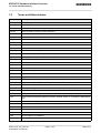
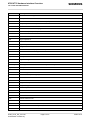
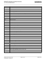
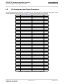
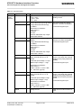
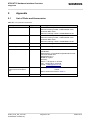
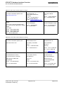
6.5 Pin Assignment and Signal Description
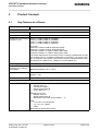
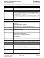
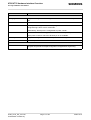
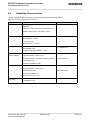
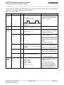
Table 17: Signal description
Function
Signal name
IO
Signal form and level
Comment
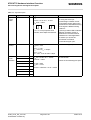
Analog
Audio
interface
VMIC
O
VOmin = 2.4V
VOtyp = 2.5V
VOmax = 2.6V
Imax = 2mA
Microphone supply for customer
feeding circuits
EPP2
O
EPN2
O
3.0Vpp differential typical @ 0dBm0 The audio output can directly
operate a 32-Ohm-loudspeaker.
4.2Vpp differential maximal @
If unused keep pins open.
3.14dBm0
Measurement conditions:
Audio mode: 6
Outstep 3
No load
Minimum differential resp. single
ended load 27Ohms
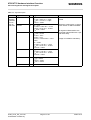
EPP1
O
EPN1
O
4.2Vpp (differential) typical @
0dBm0
The audio output can directly
operate an 8-Ohm-loudspeaker.
6.0Vpp differential maximal @
3.14dBm0
If unused keep pins open.
Measurement conditions:
Audio mode: 5
Outstep 4
No load
Minimum differential resp. single
ended load 7.5Ohms
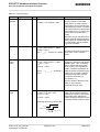
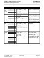
MICP1
I
MICN1
I
Differential Line Input Configuration.
Apply external bias of 1.5V at
MICN1
Full Scale Input Voltage: 1.6 Vpp
0dBm0 Input Voltage: 1.1 Vpp
Balanced or single ended microphone or line input with external
feeding circuit (using VMIC and
AGND).
If unused keep pins open.
Measurement conditions:
Audio mode: 5
^SNFI: 0,32767 => PGA = 0dB
Ri = 100 kOhm (typical)
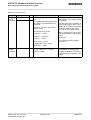
MICP2
I
MICN2
I
Differential Line Input Configuration.
Apply external bias of 1.5V at
MICN2
Full Scale Input Voltage1.6 Vpp
0dBm0 Input Voltage1.1 Vpp
Balanced or single ended microphone or line input with external
feeding circuit (using VMIC and
AGND) and accessory detection
circuit.
If unused keep pins open.
Measurement conditions:
Audio mode: 6
^SNFI: 0,32767 => PGA = 0dB
Ri = 100 kOhm (typical)
AGND
XT65_XT75_HO_v00.130
Confidential / Preliminary
Analog Ground
Page 41 of 67
GND level for external audio circuits
2006-10-12