1
INVERTER
Mitsubishi Electric Corporation Nagoya Works is a factory certified for ISO14001 (standards for environmental
management systems) and ISO9001 (standards for quality assurance management systems).
EC97J1113
[Highest level of inverter]
•Advanced driving performance makes it possible to support a wide
range of applications from variable-speed applications such as
conveyance and chemical machines to line control applications such
as winding machines and printing machines.
•Adoption of long life parts ensures more reliable operation.
•The reliable life diagnosis function notifies the maintenance time.
•It is compatible with CC-Link communication, SSCNET and other
major overseas networks. The inverter can be controlled or monitored
via network from the controller.
•Noise measures are available without an option.
Harmonic currents technique is available with a new type reactor.
¥
Features
¥
Connection with
¥
Standard
¥
Outline
Peripheral Devices
Specifications
Dimension
3
8
9
11
Drawings
¥
¥
Terminal Connection
Diagram
Terminal Specification
¥
Explanation of the
¥
Parameter List
¥
Explanations
¥
Protective
¥
Option and
¥
¥
22
Explanation
Operation Panel
of Parameters
Functions
Peripheral Devices
27
29
42
75
77
Precautions for
Operation/Selection
Precautions for Peripheral
89
Device Selection
¥
Application
¥
Main Differences and
to Motor
Compatibilities with
93
104
the FR-A500(L) Series
¥
¥
¥
Warranty
Service
International FA Center
105
106
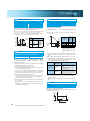
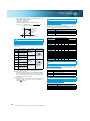
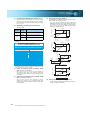
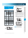
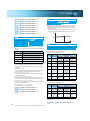
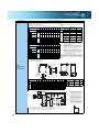
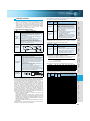
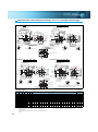
Example of torque characteristic under real sensorless vector control
When the motor SF-JR 4P is used (at 220V input)
1. Torque limit function limits the maximum
motor torque during speed control
2. Improvement of input command signal response
The delay to the input command has been minimized. The response
time has been reduced to half as compared to the conventional model
(FR-A500). It is suitable for cycle-operation applications.
Torque limit function is effective to prevent machine from damage (prevention against
damage of grinding machine tools, etc.) against the sudden disturbance torque.
0
Motor generated torque
0
Example of torque limit characteristic
0
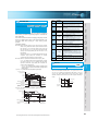
3. Quick response to the sudden load fluctuation
Torque response level to the sudden load fluctuation has been greatly improved as compared to the conventional model (FR-A500).
The motor speed variation is minimized to maintain a constant speed. It is suitable for a sawmill machine, etc.
FR-A700
FR-A500
200ms
200ms
FR-A700
940ms
560ms
300
100
Speed (r/min)
Torque (%)
Actual speed
0
0
Load torque
Time (s)
3
1
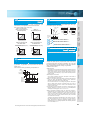
Example of actual speed variation when a load is instantaneously applied
FR-A700 series under real sensorless vector control
FR-A500 series under advanced magnetic flux vector control
The actual motor speed
increases instantly at the
moment when the load
torque decreases and then
it immediately returns to
the set speed.
Time (s)
2
Features
Standard
Specifications
3600
Speed (r/min)
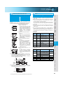
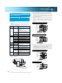
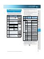
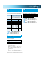
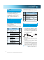
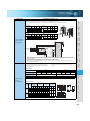
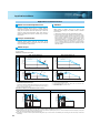
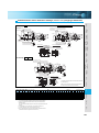
•Lineup of vector control dedicated motors
3
Type
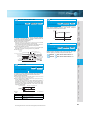
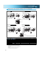
Comparison of the speed accuracy before and after the load inertia estimation
2. High accuracy torque control with
online auto tuning
SF-V5RU
Operation with high torque accuracy less susceptible to the motor
second resistance value change due to a temperature change is
realized with online tuning (adaptive magnetic flux observer). This
operation is appropriate for applications such as a winder/printing
machine (tension control) which is controlled by torque.
Base/Maximum Speed (r/min) Motor Capacity
1500/3000
1.5kW to 55kW
SF-V5RU1
1000/2000
1.5kW to 37kW
SF-V5RU3
1000/3000
1.5kW to 30kW
SF-V5RU4
500/2000
1.5kW to 15kW
SF-THY
1500/3000
75kW to 250kW
Without online tuning
120
110
FR-A500
The actual motor speed
decelerates instantly at the
moment when the load
torque increases and then
it immediately returns to
the set speed.
400
200
Example of input command signal response characteristic
When the motor SF-JR 4P 3.7kW is used
600
1800
90 180
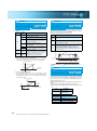
Use of vector control dedicated motor realizes 100% of the
continuous operation torque even at a low speed. It is suitable
for winder and unwinder applications. Motors with speed ratio
of 1000/2000r/min, 1000/3000r/min and 500/2000r/min
specifications are available and they can support applications
whose winding diameter greatly changes. Decreasing the
rated speed will increase the rated torque, so you can select a
motor with a smaller capacity. (The inverter one rank higher
than the motor in capacity needs to be selected depending on
the motor capacity.)
After tuning
800
ON OFF
Start command
0
1000
0
3. Vector control dedicated motor
Before tuning
1200
50
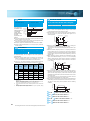
When the motor with encoder, SF-JR4P, is used (at 220V input)
1. Easy gain tuning
1500
70
Example of torque characteristic under vector control
*4 Online auto tuning (with adaptive magnetic flux observer)
Speed (r/min)
Speed (r/min)
150
Speed (r/min)
Torque (%)
1500
*4
*4
Since the load inertia of the motor is automatically estimated online
to calculate the optimum speed control gain and position loop gain,
gain adjustment is easily done. By repeating acceleration and
deceleration, load inertia is automatically estimated.
FR-A500 starts deceleration
FR-A700 starts deceleration
Motor speed
Under torque limit
*3 Regeneration unit (option) is necessary for regeneration
95
100
With online tuning
90
Vector control dedicated motor
SF-V5RU-1.5K
80
70
60
30
50
Motor temperature (¡C)
70
90
110
Example of motor temperature-torque characteristics
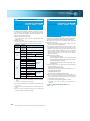
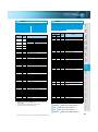
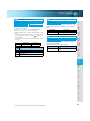
Since V/F control and advanced magnetic flux vector control operations are also available,
you can replace the conventional model (FR-A500 series) without anxiety.
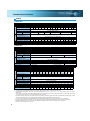
•Complement: list of functions according to driving control method
Control Method
V/F
Speed Control Torque Control Position Control Speed Control Range Speed Response
Advanced magnetic flux vector
Real sensorless vector
Vector
(FR-A7AP is necessary) (zero speed control, servo lock)
Outline
Dimension
Drawings
(0.3Hz to 60Hz driving only)
(with model adaptive speed control)
Terminal Connection
Diagram
Terminal Specification
Explanation
Output frequency (Hz)
Operation
Panel
120
Option
60
Simple Mode
Parameter
(100% means 3000r/min)
6
Instructions
0.3 3
Maximum torque for short time (0.4K to 3.7K)
Maximum torque for short time (5.5K to 500K)
150
Continuous torque (0.4 to 3.7K)
100
200
Parameter
List
(both driving/regeneration*3)
50
0
Speed control range 1:1500
Speed variation rate +-0.01%
Speed response 300rad/s
•Torque control
Torque control range 1:50
Absolute torque accuracy +-10%
Repeated torque accuracy +-5%
Protective
Functions
•Speed control
70
Motor
Speed control range 1:200
Speed response 120rad/s
100
95
*1 A plug-in option for encoder feed back control (FR-A7AP) is necessary.
*2 Only a pulse train+code system is employed for pulse command system when
performing position control with an inverter and the FR-A7AP.
The maximum pulse input is 100kpps.
*5
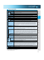
Applied Motor
1:10 (6 to 60Hz : Driving)
10 to 20rad/s
1:120 (0.5~60Hz : Driving)
20 to 30rad/s
1:200 (0.3~60Hz : Driving)
120rad/s
General-purpose motor
(without encoder)
General-purpose motor
(without encoder)
General-purpose motor
(without encoder)
1:1500 (1~1500r/min:
Both driving/regeneration) *6
300rad/s
General-purpose motor (with encoder)
Dedicated motor
*5 Only a pulse train+code method is employed for pulse command method when performing position control with an inverter and the FR-A7AP. The maximum pulse input is 100kpps.
*6 Regeneration unit (option) is necessary for regeneration
Warranty/Price Compatibilities
•
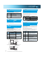
Response level has been improved.
150
Maximum torque for short time (0.4K to 3.7K)
Maximum torque for short time (5.5K to 500K)
Continuous torque (0.4 to 3.7K)
Output torque (%) (60Hz reference)
* Since torque control can not be performed in the low speed regeneration region and
at a low speed with light load, use the vector control with encoder.
200
Torque (%)
•
Output torque (%) (60Hz reference)
200%
0.3Hz
•
Peripheral
Devices
Vector control operation can be performed using a motor with encoder*1. Torque control/position control*2 as well as
fast response/high accuracy speed control (zero speed control, servo lock) can be realized with the inverter.
Inquiry
High accuracy/fast response speed operation by the vector control
can be performed with a general-purpose motor without encoder.
Maximum of
high torque can be generated at an ultra low
speed of
(0.4K to 3.7K).
Torque control operation can be performed also.* (Torque control
_20%, repeated torque
range 1:20, absolute torque accuracy +
_10%)
accuracy +
4
QP value
.3
.5
.7
1
2
3
5
7
10
20
30
Frequency [MHz]
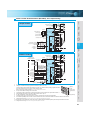
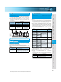
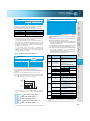
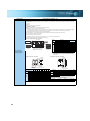
Because of the built-in inrush current limit circuit, the current at
power on can be restricted.
Features
•The RS-485 terminals are equipped as standard in addition to
•
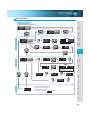
Inverter
Up to 42 units
can be connected
•
only inverters
( when
are connected )
FR-A7NC
Terminating resistor
CC-Link
dedicated cable
FR-A7NC
•
Terminating resistor
CC-Link network
•
The inverter can be connected to Mitsubishi motion controller
through the SSCNETIII. The SSCNETIII employs a high-speed
synchronous serial communication system and is appropriate for
the synchronous operation.
(SSCNET…Servo System Controller Network)
the PU connector.
You can make RS-485 communication with the operation panel
or parameter unit connected to the PU connector.
Since the inverter can be connected to the network with terminals,
multi-drop connection is also easily done.
Modbus-RTU (Binary) protocol has been added for
communications in addition to the conventional Mitsubishi
inverter protocol (computer link).
As a USB connector (USB1.1B connector) is standard equipped,
communication with a personnel computer can be made with a
USB cable only.
Using the RS-485 terminal or USB connector, you can make
communication by the FR-Configurator (setup S/W).
Motion controller
•Parameter management (parameter setting, file storage, printing) is easy.
•Maintenance and setup of the inverter can be done from a
personal computer connected with USB.
Mechanical resonance is easily avoided with machine analyzer function.
Parameter setting after
replacement of the FRA500 series can be made
with a parameter automatic
conversion function.
•
•
•An operation panel can be removed and a parameter unit
can be connected.
•Setting such as direct input method with a numeric keypad,
•
•
operation status indication, and help function are usable.
Eight languages can be displayed.
Parameter setting values of a maximum
of three inverters can be stored.
Since a battery pack type (available soon)
is connectable, parameter setting and
parameter copy can be performed without
powering on the inverter.
USB
connector
RS-485
terminals
Servo
amplifier
Option (sell separately) Standard (provided)
•
Inverter
•
Possible to copy parameters with operation panel.
Parameter setting values are stored in the operation panel
and optional parameter unit (FR-PU07).
Operation is easy with the setting dial.
Cooling fans are provided on top of the
inverter.
Cooling fans can be replaced without
disconnecting main circuit wires.
Example of
parameter change
The inverter can be connected with networks such as DeviceNET™, PROFIBUS-DP, LONWORKS, EtherNet (available soon)
and CANopen (available soon) when communication options
are used.
LONWORKS is a registered trademark of Echelon Corporation and DeviceNet is of ODVA
Other company and product names herein are the trademarks of their respective owners.
PU/EXT operation
mode example
•Operation panel is detachable and can
•
•
5
be installed on the enclosure surface.
(cable connector option is required)
PU/EXT (operation mode) can be
switched with a single touch.
A dial/key operation lock function
prevents operational errors.
A removable terminal block was adapted.
(The terminal block of the FR-A700 series
is compatible with that of the FR-A500
series. Note that some functions of the
FR-A700 series are restricted when using
the terminal block of the FR-A500 series.
Note that the wiring cover is not compatible.)
Since a wiring cover can be mounted after wiring, wiring work
is easily done.
Peripheral
Devices
Standard
Warranty/Price
SSCNETIII
Inquiry
FR-A7NS
Specifications
Option
CPU
Inverter
Master
Standard (built-in)
Instructions
PLC
75K or more
Motor
Power
supply
unit
Standard (built-in) Option (sell separately)
Compatibilities
The inverter can be connected to the Mitsubishi PLC (Q, QnA, A
series, etc.) through the CC-Link. It is compatible with the CCLink Ver.1.1 and Ver.2.0. The inverter operation, monitoring and
parameter setting change can be done from the PLC.
(Line noise filter)
Standard (built-in)
Simple Mode
(Radio noise filter)
55K or less
6
Drawings
Dimension
Outline
Capacitive Filter Zero-phase Reactor DC Reactor
Explanation
*3 Excerpts from “Periodic check of the transistorized inverter” of JEMA (Japan Electrical
Manufacturer’s Association).
suppressions of power-supply harmonics (conversion
coefficient: K5=0) can be connected.
Diagram
2 to 3 years
5 years
5 years
•A high power factor converter (FR-HC, MT-HC) for effective
EN61800-3 2nd Environment QP level
Terminal Connection
10 years
10 years
10 years
130
120
110
100
90
80
70
60
50
40
30
20
10
0
.15 .2
Terminal Specification
Cooling fan
Main circuit smoothing capacitor
Printed board smoothing capacitor
[dBµV]
Panel
*3
DC reactor (FR-HEL)
Operation
Life Guideline of the FR-A700 Guideline of JEMA
AC reactor (FR-HAL)
Parameter
Components
EMC filter is ON
*1 Leakage current will increase when the EMC filter is selected.
*2 Since the leakage current when using the EMC filter for the 200V class 0.4K and
0.75K is small, the filter is always valid (setting connector is not provided).
*3 Refer to the EMC installation manual for compliance conditions.
Life indication of life components
which limit harmonics current flowing into the power supply
and improve the power factor, are available as options. (For
the 75K or more, a DC reactor is supplied as standard.)
List
*1 Ambient temperature : annual average 40°C (free from corrosive gas, flammable
gas, oil mist, dust and dirt).
Since the design life is a calculated value, it is not a guaranteed value.
*2 Output current: equivalent to rating current of the Mitsubishi standard motor (4 poles).
•
•
*4 Any one of main circuit capacitor, control circuit capacitor, inrush current limit
circuit and cooling fan reaches the output level, an alarm is output.
For the main circuit capacitor, the capacitor capacity needs to be measured during
a stop by setting parameter.
•A compact AC reactor (FR-HAL) and a DC reactor (FR-HEL),
FILTER
Parameter
•
with adoption of a new technology (low-noise of
switching power, low noise of inverter element).
Because of the newly developed built-in noise
filter (EMC filter), the inverter itself can comply
with the EMC Directive (2nd Environment*3).
(To make the EMC filter of the inverter valid*1,
set ON/OFF connector*2 to ON.)
Functions
•
•Reduction of noise generated from the inverter was achieved
Protective
capacitor or inrush current limit circuit can be monitored.
Since a parts life alarm can be output*4 by self-diagnosis,
troubles can be avoided.
ON
•Degrees of deterioration of main circuit capacitor, control circuit
to 10 years of design life*1. The life of the cooling fan is further
extended with ON/OFF control of the cooling fan.
Longevity of capacitor was achieved with the adoption of a
design life of 10 years*1*2.
(A capacitor with specification of 5000 hours at 105 °C ambient
temperature is adapted.)
OFF
•The life of a newly developed cooling fan has been extended
USB connector
•
•
Since the original operation continuation at instantaneous
power failure function has been newly adopted, the motor
continues running without coasting even if an instantaneous
power failure occurs during operation.
•
the analog input terminal (two points), you can switch
between voltage (0 to 5V, 0 to 10V) and current (0 to 20mA).
You can display the ON/OFF status of the I/O terminals on the
operation panel.
Two points relay output is available.
P/+
(FR-HAL)
PR
T/L3
U
Earth
Compliance with both 240V power supply (55K or less) and
480V power supply as standard.
(Ground)
DC reactor
Noise filter
(FR-HEL)
(FR-BLF)
For the 75K or more, a
DC reactor is supplied.
Always install the reactor.
The 55K or less has
a built-in zero-phase
reactor.
V W
Noise filter
(FR-BSF01, FR-BLF)
Option
P/+ N/-
Install a noise filter to reduce
the electromagnetic noise
generated from the inverter.
Effective in the range from
about 1MHz to 10MHz. A wire
should be wound four turns at
a maximum.
Instructions
R/L1 S/L2
P/+ P1
Inverter Capacity
Indicate capacity (kW)
Brake unit
(FR-BU*1, MT-BU5*2)
Compatibilities
Symbol
0.4K~500K
Motor
Motor
Voltage
Earth (Ground)
Devices connected to the output
PR
Applied Motor
(kW)
0.4
0.75
FR-A720-3.7K
1.5
2.2
3.7
5.5
FR-A720-7.5K
7.5
11
15
18.5
22
FR-A720-22K
30
37
45
55
75
90
FR-A720-55K
110
132
160
185
220
250
280
315
355
400
450
500
Three-phase 200V class
FR-A720Three-phase 400V class
FR-A740-
: Available models
7
: Not available
High power factor converter
Power regeneration
Resistor unit
(FR-HC*1, MT-HC*2 )
common converter
(FR-BR*1, MT-BR5*2 )
Power supply harmonics
can be greatly suppressed.
Install this as required.
*1 Compatible with the 55K or less.
*2 Compatible with the 75K or more.
(FR-CV*1 )
Power regeneration
converter (MT-RC*2 )
Great braking capability
is obtained.
Install this as required.
The regenerative braking
capability of the inverter
can be exhibited fully.
Install this as required.
Do not install a power factor correction
capacitor, surge suppressor or radio noise
filter on the output side of the inverter. When
installing a moulded case circuit breaker on
the output side of the inverter, contact each
manufacturer for selection of the moulded
case circuit breaker.
Warranty/Price
PR
Inquiry
P/+
P/+
FR-A720-0.4K
Devices
*3 Compatible with the 22K or less.
AC reactor
* The inverter may trip and the motor may coast depending on the load condition.
200V class
400V class
Peripheral
Features
(FR-ABR*3 )
Braking capability of the
inverter built-in brake can be
improved. Remove the jumper
across terminal PR-PX when
connecting the high-duty
brake resistor. (7.5K or less)
Simple Mode
•For
Time
High-duty brake resistor
Reactors (option) must be used when
power harmonics measures are
taken, the power factor is to be
improved or the inverter is installed
near a large power supply system
(1000kVA or more). The inverter may
be damaged if you do not use
reactors. Select the reactor according
to the model. Remove the jumpers
across terminals P-P1 to connect the
DC reactor to the 55K or less.
List
Decelerates to stop
2
4
Standard
Terminal Connection
Operation
Reactor (FR-HAL, FR-HEL option)
Parameter
Motor speed
supply
Functions
Power failure occurrence
Power
Install the magnetic contactor to
ensure safety. Do not use this
magnetic contactor to start and stop
the inverter. Doing so will cause the
inverter life to be shorten.
Protective
Speed command by pulse train signal (single pulse) from the
controller etc. can be directly input to the inverter.
Since pulse can be output from the inverter at the same time,
synchronous speed operation of inverters can be performed.
(maximum pulse input 100kpps, output 50kpps)
Symbol
Specifications
Magnetic contactor (MC)
Earth (Ground)
To prevent an electric shock, always earth
(ground) the motor and inverter. For
reduction of induction noise from the power
line of the inverter, it is recommended to wire
the earth (ground) cable by returning it to the
earth (ground) terminal of the inverter.
8
Explanation
or undervoltage occurred to prevent the motor from coasting.
For fail-safe of machine tool, etc., it is effective to stop the
motor when a power failure has occurred.
Outline
•The motor can be decelerated to a stop when a power failure
Diagram
In addition to the 0.4K to 7.5K, a brake transistor is built-in to the
11K, 15K, 18.5K and 22K. A brake resistor (option) can be also
connected to the 11K to 22K.
The breaker must be selected
carefully since an in-rush current
flows in the inverter at power on.
Dimension
or earth leakage breaker (ELB), fuse
Drawings
Moulded case circuit breaker (MCCB)
Terminal Specification
For operations of such as a pressing machine, in which an
instantaneous regeneration occurs, overvoltage trip can be
made less likely to occur by increasing frequency during
regeneration.
Panel
Tuning accuracy equivalent to that of the conventional tuning of
“with rotation mode” is realized with the auto tuning without
motor running. Even for the machine which disallows a motor to
run during tuning, the motor performance can be maximized.
The sophisticated auto tuning function which measures circuit constants
of the motor allows sensorless vector control with any kind of motor.
A personal computer and an
inverter can be connected
with a USB (Ver1. 1) cable.
Use within the permissible power
supply specifications of the inverter.
Parameter
Three-phase AC power supply
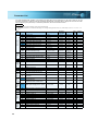
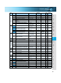
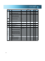
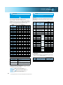
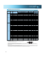
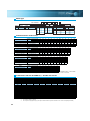
Standard Specifications
Rating
200V class
Type FR-A720-
K
Applicable motor capacity (kW) *1
Rated capacity (kVA) *2
Output
Rated current (A) *3
Overload current rating *4
0.4 0.75 1.5
2.2
3.7
5.5
7.5
0.4
1.1
2.2
4.2
3.7
6.7
5.5
9.2
7.5
12.6
0.75
1.9
11
18.5
22
30
37
45
55
11
15 18.5
17.6 23.3 29
15
22
34
30
44
37
55
45
67
55
82
75
90
75
90
110 132
288 346
3
5
8
11
17.5
24
33
46
61
76
90 115 145 175 215
(245) (294)
150% 60s, 200% 3s (inverse time characteristics) ambient temperature 50°C
Three-phase 200 to 240V
150% torque/
100% torque/ 100% torque/
20% torque/
20% torque/
10% torque/
3%ED
3%ED
2%ED
continuous *6
continuous
continuous
Power supply
Voltage *5
Regenerative Maximum value/
braking torque permissible duty
Rated input
AC voltage/frequency
Permissible AC voltage fluctuation
Permissible frequency fluctuation
Power supply capacity (kVA) *7
1.5 2.5
Protective structure (JEM 1030) *9
Cooling system
Self-cooling
Approx. mass (kg)
1.9 2.3
1.5
3.1
Three-phase 200 to 220V 50Hz, 200 to 240V 60Hz
4.5
3.8
170 to 242V 50Hz,170 to 264V 60Hz
±5%
5.5
9
12
17
20
28
34
41
52
Enclosed type (IP20) *8
Forced air cooling
3.8
3.8
7.1
7.1 7.5 13
13
14
23
66
80 100 110
Open type (IP00)
132
35
70
35
58
70
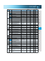
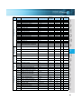
400V class
0.4
0.75
0.4
1.1
1.5
0.75
1.9
2.5
Output
Type FR-A740-
K
Applicable motor capacity (kW) *1
Rated capacity (kVA) *2
Rated current (A)
Overload current rating *4
Power supply
Voltage *5
Regenerative Maximum value/
braking torque permissible duty
Rated input
AC voltage/frequency
Permissible AC voltage fluctuation
Permissible frequency fluctuation
Power supply capacity (kVA) *7
Protective structure (JEM 1030) *9
Cooling system
Approx. mass (kg)
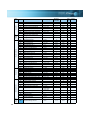
Type FR-A740-
K
Output
Applicable motor capacity (kW) *1
Rated capacity (kVA) *2
Rated current (A)*3
Overload current rating *4
Power supply
Voltage*5
Regenerative Maximum value/
braking torque permissible duty
Rated input
AC voltage/frequency
Permissible AC voltage fluctuation
Permissible frequency fluctuation
Power supply capacity (kVA) *7
Protective structure (JEM 1030) *9
Cooling system
Approx. mass (kg)
1.5
45
55
1.5
2.2
3.7
5.5
7.5
11
15
18.5
22
30
37
45
3
4.6
6.9
9.1
13
17.5 23.6
29
32.8 43.4
54
65
4
6
9
12
17
23
31
38
44
57
71
86
150% 60s, 200% 3s (inverse time characteristics) ambient temperature 50°C
Three-phase 380 to 480V
2.2
3.7
5.5
7.5
55
84
110
100% torque/2%ED
11
15
18.5
22
20% torque/continuous *6
30
37
20% torque/continuous
Three-phase 380 to 480V 50Hz/60Hz
Self-cooling
3.5
3.5
3.5
323 to 528V 50Hz/60Hz
±5%
5.5
9
12
17
20
28
34
41
Enclosed type (IP20) *8
Forced air cooling
3.5
3.5
6.5
6.5
7.5
7.5
13
13
75
132
1.5
2.5
90
4.5
110
160
185
220
250
280
315
355
52
66
80
100
Open type (IP00)
23
35
35
400
450
500
37
75
90
110 132 160 185 220 250 280 315 355 400 450 500
110 137 165 198 248 275 329 367 417 465 521 587 660 733
144 180 216 260 325 361 432 481 547 610 683 770 866 962
(122) (153) (184) (221) (276) (307) (367) (409) (465) (519) (581) (655) (736) (818)
150% 60s, 200% 3s (inverse time characteristics) ambient temperature 50°C
Three-phase 380 to 480V
10% torque/continuous
Three-phase 380 to 480V 50Hz/60Hz
110
137
165
198
248
50
57
72
72
110
323 to 528V 50Hz/60H
±5%
275 329 367 417
Open type (IP00)
Forced air cooling
110 175 175 175
465
521
587
660
733
260
260
370
370
370
*1. The applicable motor capacity indicated is the maximum capacity applicable for use of the Mitsubishi 4-pole standard motor.
*2. The rated output capacity indicated assumes that the output voltage is 220V for 200V class and 440V for 400V class.
*3. When operating the inverter of 75K or more with a value larger than 2kHz set in Pr. 72 PWM frequency selection, the rated output current is the value in
parenthesis.
*4. The % value of the overload current rating indicates the ratio of the overload current to the inverter's rated output current. For repeated duty, allow time for
the inverter and motor to return to or below the temperatures under 100% load.
*5. The maximum output voltage does not exceed the power supply voltage. The maximum output voltage can be changed within the setting range. However,
*6.
*7.
*8.
*9.
9
the pulse voltage value of the inverter output side voltage remains unchanged at about 2 that of the power supply.
For the 11K to 22K capacities, using the dedicated external brake resistor (FR-ABR) will achieve the performance of 100% torque/6%ED.
The power supply capacity varies with the value of the power supply side inverter impedance (including those of the input reactor and cables).
When the hook of the inverter front cover is cut off for installation of the plug-in option, the inverter changes to an open type (IP00).
FR-DU07:IP40 (except for the PU connector)
Peripheral
Devices
Standard
Specifications
Outline
Dimension
Drawings
Terminal Connection
Diagram
Terminal Specification
Explanation
Operation
Panel
Parameter
List
Explanations
of
Parameters
Protective
Functions
Options
Instructions
Motor
Compatibility
Warranty
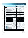
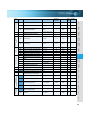
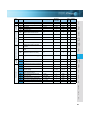
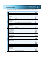
Control specifications
Operation specifications
Output signals
Indication
Environment
*1.
*2.
*3.
*4.
*5.
Ambient Temperature
-10°C to +50°C (non-freezing)
90%RH maximum (non-condensing)
Ambient humidity
-20°C to +65°C
Storage temperature*4
Indoors (without corrosive gas, flammable gas, oil mist, dust and dirt etc.)
Atmosphere
Altitude/vibration
Maximum 1000m above sea level, 5.9m/s2 or less *5 (conforms to JIS C 60068-2-6)
Only when the option (FR-A7AP) is mounted
Can be displayed only on the operation panel (FR-DU07).
Can be displayed only on the parameter unit (FR-PU07/FR-PU04).
Temperature applicable for a short period in transit, etc.
2.9m/s2 or less for the 160K or more.
Inquiry
Soft-PWM control/high carrier frequency PWM control (selectable from among V/F control, advanced magnetic flux vector control and
real sensorless vector control) / vector control (when used with option FR-A7AP)*1
0.2 to 400Hz
Output frequency range
0.015Hz/0 to 60Hz (terminal 2, 4: 0 to 10V/12bit)
Frequency Analog input
0.03Hz/0 to 60Hz (terminal 2, 4: 0 to 5V/11bit, 0 to 20mA/about 11bit, terminal 1: 0 to ±10V/12bit)
setting
0.06Hz/0 to 60Hz (terminal 1: 0 to ±5V/11bit)
resolution
0.01Hz
Digital input
Within ±0.2% of the max. output frequency (25°C±10°C)
Frequency Analog input
accuracy
Within 0.01% of the set output frequency
Digital input
Voltage/frequency characteristics Base frequency can be set from 0 to 400Hz Constant torque/variable torque pattern or adjustable 5 points V/F can be selected
200% 0.3Hz (0.4K to 3.7K), 150% 0.3Hz (5.5K or more) (under real sensorless vector control or vector control)
Starting torque
Manual torque boost
Torque boost
Acceleration/deceleration time 0 to 3600s (acceleration and deceleration can be set individually), linear or S-pattern acceleration/deceleration mode, backlash
setting
measures acceleration/deceleration can be selected.
DC injection brake
Operation frequency (0 to 120Hz), operation time (0 to 10s), operation voltage (0 to 30%) variable
Stall prevention operation level
Operation current level can be set (0 to 220% adjustable), whether to use the function or not can be selected
Torque limit level
Torque limit value can be set (0 to 400% variable)
• Terminal 2, 4: 0 to 10V, 0 to 5V, 4 to 20mA can be selected
• Terminal 1: -10 to +10V, -5 to +5V can be selected
Frequency Analog input
setting
Input using the setting dial of the operation panel or parameter unit
Digital
input
signal
Four-digit BCD or 16 bit binary (when used with option FR-A7AX)
Start signal
Forward and reverse rotation or start signal automatic self-holding input (3-wire input) can be selected.
You can select any twelve signals using Pr. 178 to Pr. 189 (input terminal function selection) from among multi speed selection, remote setting,
stop-on-contact, second function selection, third function selection, terminal 4 input selection, JOG operation selection, selection of
automatic restart after instantaneous power failure, flying start, external thermal relay input, inverter operation enable signal (FR-HC/FR-CV
connection), FR-HC connection (instantaneous power failure detection), PU operation/external inter lock signal , external DC injection brake
operation start, PID control enable terminal, brake opening completion signal, PU operation/external operation switchover, load pattern
Input signals
selection forward rotation reverse rotation boost, V/F switching, load torque high-speed frequency, S-pattern acceleration/deceleration C
switchover, pre-excitation, output stop, start self-holding selection, control mode changing, torque limit selection, start-time tuning start
external input, torque bias selection 1, 2 *1, P/PI control switchover, forward rotation command, reverse rotation command, inverter reset,
PTC thermistor input, PID forward reverse operation switchover, PU-NET operation switchover, NET-external operation switchover, and
command source switchover.
Pulse train input
100kpps
Maximum/minimum frequency setting, frequency jump operation, external thermal relay input selection, polarity reversible operation,
automatic restart after instantaneous power failure operation, commercial power supply-inverter switchover operation, forward/reverse
rotation prevention, remote setting, brake sequence, second function, third function, multi-speed operation, original operation
continuation at instantaneous power failure, stop-on-contact control, load torque high speed frequency control, droop control,
Operational functions
regeneration avoidance, slip compensation, operation mode selection, offline auto tuning function, online auto tuning function, PID
control, computer link operation (RS-485), motor end orientation*1, machine end orientation*1, pre-excitation, notch filter, machine
analyzer*1, easy gain tuning, speed feed forward, and torque bias*1
You can select any signals using Pr. 190 to Pr. 196 (output terminal function selection) from among inverter running, up-to-frequency,
instantaneous power failure/undervoltage, overload warning, output frequency (speed) detection, second output frequency (speed)
detection, third output frequency (speed) detection, regenerative brake prealarm, electronic thermal relay function pre-alarm, PU
operation mode, inverter operation ready, output current detection, zero current detection, PID lower limit, PID upper limit, PID forward
rotation reverse rotation output, commercial power supply-inverter switchover MC1, commercial power supply-inverter switchover MC2,
commercial power supply-inverter switchover MC3, orientation completion*1, brake opening request, fan fault output, heatsink overheat
Operating status
pre-alarm , inverter running/start command on, deceleration at an instantaneous power failure, PID control activated, during retry, PID
output interruption, life alarm, alarm output 1, 2, 3 (power-off signal), power savings average value update timing, current average
monitor, maintenance timer alarm, remote output, forward rotation output*1, reverse rotation output*1, low speed output, torque detection,
regenerative status output *1, start-time tuning completion, in-position completion*1, minor failure output and alarm output. Open collector
output (5 points), relay output (2 points) and alarm code of the inverter can be output (4 bit) from the open collector.
In addition to the above, you can select any signals using Pr. 313 to Pr. 319 (extension output terminal function selection) from among
When used with the
control circuit capacitor life, main circuit capacitor life, cooling fan life, inrush current limit circuit life. (only positive logic can be set for
FR-A7AY, FR-A7AR
(option)
extension terminals of the FR-A7AR)
50kpps
Pulse train output
You can select any signals using Pr. 54 FM terminal function selection (pulse train output) and Pr. 158 AM terminal function selection (analog
output) from among output frequency, motor current (steady or peak value), output voltage, frequency setting, operation speed, motor
Pulse/analog output
torque, converter output voltage (steady or peak value), electronic thermal relay function load factor, input power, output power, load
meter, motor excitation current, reference voltage output, motor load factor, power saving effect, regenerative brake duty ,PID set
point, PID measured value, motor output, torque command, torque current command, and torque monitor.
Output frequency, motor current (steady or peak value), output voltage, frequency setting, running speed,motor torque, overload,
converter output voltage (steady or peak value), electronic thermal relay function load factor, input power, output power, load meter,
motor excitation current, cumlative energization time, actual operation time, motor load factor, cumulative power, energy saving effect,
Operating status cumulative saving power, regenerative brake duty, PID set point, PID measured value, PID deviation, inverter I/O terminal monitor,
PU
(FR-DU07/
input terminal option monitor*2, output terminal option monitor*2, option fitting status*3, terminal assignment status*3, torque
FR-PU07/
command, torque current command, feed back pulse*1,motor output
FR-PU04)
Alarm definition is displayed during the protective function is activated, the output voltage/current/frequency/cumulative energization
Alarm definition
time right before the protection function was activated and past 8 alarm definitions are stored.
Interactive guidance Operation guide/trouble shooting with a help function*3
Overcurrent during acceleration, overcurrent during constant speed, overcurrent during deceleration, overvoltage during acceleration,
overvoltage during constant speed, overvoltage during deceleration, inverter protection thermal operation, motor protection thermal
operation, heatsink overheat, instantaneous power failure occurrence, undervoltage, input phase failure, motor overload, output side
earth (ground) fault overcurrent, output short circuit, main circuit element overheat, output phase failure, external thermal relay operation,
PTC thermistor operation, option alarm, parameter error, PU disconnection, retry count excess, CPU alarm, operation panel power
Protective/warning function
supply short circuit, 24VDC power output short circuit, output current detection value excess, inrush current limit circuit alarm,
communication alarm (inverter), USB error, opposite rotation deceleration error, analog input error, fan fault, overcurrent stall prevention,
overvoltage stall prevention, regenerative brake prealarm, electronic thermal relay function prealarm, PU stop, maintenance timer
alarm*2, brake transistor alarm, parameter write error, copy operation error, operation panel lock, parameter copy alarm, speed limit
indication, encoder no-signal*1, speed deviation large*1, overspeed*1, position error large*1, encoder phase error*1
Control method
Features
Common specifications
10
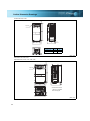
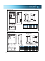
Outline Dimension Drawings
7.5
FR-A720-0.4K, 0.75K
245
260
2-φ6 hole
6
5
7.5
95
110
D
Inverter Type
D
D1
110
125
21
36
D1
FR-A720-0.4K
FR-A720-0.75K
(Unit: mm)
7.5
FR-A720-1.5K, 2.2K, 3.7K
FR-A740-0.4K, 0.75K, 1.5K, 2.2K, 3.7K
6
125
150
7.5
245
260
2-φ6 hole
140
5
45.5
* The FR-A740-0.4K to
1.5K are not provided
with a cooling fan.
144
(Unit: mm)
11
Compatibility
Instructions
230
250
Options
2-φ10 hole
Protective
Functions
H
H1
D
D1
260
245
170
84
300
285
190
101.5
Terminal Connection
Diagram
Terminal Specification
Explanation
Outline
Dimension
Drawings
220
211
(Unit: mm)
190
10.5
250
Operation
Panel
10
Parameter
List
FR-A720-15K, 18.5K, 22K
FR-A740-18.5K, 22K
Explanations
of
Parameters
Inverter Type
Motor
10
FR-A720-5.5K, 7.5K
FR-A740-5.5K, 7.5K
FR-A720-11K
FR-A740-11K, 15K
Warranty
10
D
Inquiry
380
400
7.5
195
10
6
101.5
D1
Standard
Specifications
H
H1
Peripheral
Devices
Features
7.5
FR-A720-5.5K, 7.5K, 11K
FR-A740-5.5K, 7.5K, 11K, 15K
2-φ6 hole
(Unit: mm)
12
H2
FR-A720-30K, 37K, 45K, 55K
FR-A740-30K, 37K, 45K, 55K
H
10
H1
2-φd hole
W2
3.2
W1
D
W
Inverter Type
FR-A720-30K
FR-A740-30K
FR-A720-37K, 45K
FR-A740-37K, 45K, 55K
FR-A720-55K
W
W1
W2
H
H1
H2
d
D
325
270
10
550
530
10
10
195
435
380
12
550
525
15
12
250
465
410
12
700
675
15
12
250
(Unit: mm)
FR-A740-75K, 90K
DC reactor supplied
15
2-φ12hole
Rating plate
2-terminal
(for M12 bolt)
P1
P
H1
620
595
H 10
P1, P
E
W1
W
2
4-installation hole
(for M6 screw)
Within D
Earth (ground) terminal
(for M6 screw)
400
465
10
DC Reactor
Type
3.2
300
FR-HEL-H75K
(FR-A740-75K)
FR-HEL-H90K
(FR-A740-90K)
W
W1
H
H1
D
Mass
(Kg)
140
120
320
295
185
16
150
130
340
310
190
20
(Unit: mm)
13
15
Features
FR-A720-75K, 90K
FR-A740-110K, 132K
10
400
465
Operation
Panel
Terminal Connection
Diagram
Terminal Specification
Explanation
Outline
Dimension
Drawings
715
740
Standard
Specifications
Peripheral
Devices
2-φ12 hole
3.2
Parameter
List
360
DC reactor supplied
Rating plate
Protective
Functions
Options
P
E
W1
W
2
4-installation hole
(for S screw)
Within D
DC Reactor Type
W1
H
H1
D
S
Mass (kg)
150
130
340
310
190
M6
17
FR-HEL-90K (FR-A720-90K)
150
130
340
310
200
M6
19
FR-HEL-H110K (FR-A740-110K)
150
130
340
310
195
M6
22
FR-HEL-H132K (FR-A740-132K)
175
150
405
370
200
M8
26
Motor
W
FR-HEL-75K (FR-A720-75K)
Instructions
Earth (ground) terminal
(for M6 screw)
(Unit: mm)
Compatibility
P
Warranty
H1
H 10
P1
Inquiry
P1
Explanations
of
Parameters
2-terminal
(for M12 bolt)
14
FR-A740-160K, 185K
15
3-φ12 hole
DC reactor supplied
Rating plate
2-terminal
(for M12 bolt)
P1
H1
985
1010
H 10
P1
P
P
E
4-installation hole
(for S screw)
W1
W
2
Within D
Earth (ground) terminal
(for M6 screw)
200
3.2
10
12
49
200
49
380
W
W1
H
H1
D
S
Mass
(kg)
FR-HEL-H160K
(FR-A740-160K)
175
150
405
370
205
M8
28
FR-HEL-H185K
(FR-A740-185K)
175
150
405
370
240
M8
29
DC Reactor Type
498
185
211.5
150.5
450
(Unit: mm)
FR-A740-220K, 250K, 280K
3-φ12 hole
DC reactor supplied
Rating plate
2-S2 eye nut
2-terminal (for bolt)
H 10
H1 10
P1
1010
985
P1
P
P
E
12
W1
1
W
2
300
380
680
N/-
P1
U
P/+
W
V
214
S/L2
* Remove the eye nut after installation of the product.
DC Reactor
Type
148
R/L1 T/L3
Within D
Earth (ground) terminal
(for S1 screw)
3.2
300
4-installation hole
(for S screw)
FR-HEL-H220K
(FR-A740-220K)
FR-HEL-H250K
(FR-A740-250K)
FR-HEL-H280K
(FR-A740-280K)
W
W1
H
H1
D
S
S1
S2
φ
Mass
(kg)
175
150
405
370
240
M8
M6
M6
M12
30
190
165
440
400
250
M8
M8
M8
M12
35
190
165
440
400
255
M8
M8
M8
M16
38
(Unit: mm)
15
FR-A740-315K, 355K
Outline
Dimension
Drawings
Standard
Specifications
1330
1300
Peripheral
Devices
Features
3-φ12 hole
315
315
4.5
790
P1
U
P/+
W
V
Parameter
List
185
222
N/-
Operation
Panel
T/L3
S/L2
4.5
440
194
R/L1
Terminal Connection
Diagram
Terminal Specification
Explanation
12
Explanations
of
Parameters
DC reactor supplied
Rating plate
2-M8 eye nut
P1
Protective
Functions
2-terminal (for M16 bolt)
Options
495 10
450 10
P1
P
P
210
4-installation hole
(for M10 screw)
Instructions
E
185
Within 250
Earth (ground) terminal
(for M8 screw)
* Remove the eye nut after installation of the product.
(Unit: mm)
Compatibility
46
Warranty
42
FR-HEL-H355K (FR-A740-355K)
Motor
Mass (kg)
Inquiry
DC Reactor Type
FR-HEL-H315K (FR-A740-315K)
16
FR-A740-400K, 450K, 500K
12
1580
1550
4-φ12 hole
4.5
300
300
300
4.5
440
995
950
P/+
U
V
W
189
P1
185
227
R/L1 S/L2 T/L3 N/-
DC reactor supplied
DC reactor supplied
Rating plate
40
Rating plate
P1
2-M8 eye nut
2-terminal
4- 15 hole
P1
2-terminal
4- 15 hole
10
Earth (ground) terminal
(for M12 screw)
P
500
455
10
P1
E
* Remove the eye nut after installation of the product.
40
75
Within 245
2-M12 eye nut
40
75
40
P
P
P1
P
E
220
4-installation hole
(for M10 screw)
Within D
Within H
195
Within W
Earth (ground) terminal
(for M8 screw)
* Remove the eye nut after installation of the product.
150
215
W
D
Mass
(kg)
FR-HEL-H400K
(FR-A740-400K)
235
250
50
FR-HEL-H450K
(FR-A740-450K)
240
270
57
DC Reactor Type
4-installation hole
(for M10 screw)
DC Reactor Type
FR-HEL-H500K
(FR-A740-500K)
D1
10
D
10
H
D
D1
Mass
(kg)
345
455
405
67
(Unit: mm)
17
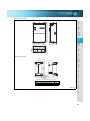
Operation panel (FR-DU07)
<Panel cutting dimension drawing>
Panel
FR-DU07
27.8
Peripheral
Devices
21
Airbleeding
hole
22
44
50
44
6
3
3.2max
Features
<Outline drawing>
72
78
81
16
3
2-M3 screw
Cable
72
Operation panel connection connector
(FR-ADP)
25
(Unit: mm)
Outline
Dimension
Drawings
Parameter unit (option) (FR-PU07)
Standard
Specifications
20
3
3
<Panel cutting dimension drawing>
Terminal Connection
Diagram
Terminal Specification
Explanation
<Outline drawing>
25.05
(11.45)
2.5
*1
40
Air-bleeding
hole
51
50
*1
40
Operation
Panel
(14.2)
83
Parameter
List
4-R1
*1
4-φ4 hole
(Effective depth 5.0)
Protective
Functions
26.5
M3 screw *2
*1
When installing the FR-PU7 on the enclosure, etc., remove screws for fixing
*2
the FR-PU07 to the inverter or fix the screws to the FR-PU07 with M3 nuts.
Select the installation screws whose length will not exceed the effective
depth of the installation screws threads.
80.3
(Unit: mm)
<Outline drawing>
Instructions
Parameter unit (option) (FR-PU04)
Options
26.5
Explanations
of
Parameters
57.8
56.8
67
135
*1
<Panel cutting dimension drawing>
16.5
Motor
Compatibility
5-M3 screw
Effective
depth 4.5
40
40
Select the installation screws whose length will not exceed the effective depth of the installation screws threads.
(Unit: mm)
Warranty
1.25
1.5
5-φ4 hole
13 1.5
17
20
14.5
80
125
23.75
11.75
81.5
10.5
18.5
15
21.5
72
13
Inquiry
24
48
18
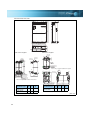
Heatsink protrusion procedure
When encasing the inverter in an enclosure, the generated heat amount in an enclosure can be greatly reduced by installing
the heatsink portion of the inverter outside the enclosure.
When installing the inverter in a compact enclosure, etc., this installation method is recommended. For the 160K or more, a
heatsink can be protruded outside the enclosure without using an attachment.
zWhen using a heatsink protrusion attachment (FR-A7CN)
For the FR-A720-1.5K to 90K and FR-A740-0.4K to 132K, a heatsink can be protruded outside the enclosure using a heatsink protrusion attachment (FRA7CN).
Refer to the instruction manual of the heatsink protrusion attachment (FR-A7CN) for details.
Drawing after attachment installation (when used with the FR-A7CN)
Attachment
W
D
S screw
D1
D2
H3
H1
H
H2
Panel
Attachment
Panel
Type
FR-A7CN01
FR-A7CN02
FR-A7CN03
FR-A7CN04
FR-A7CN05
FR-A7CN06
FR-A7CN07
FR-A7CN08
FR-A7CN09
FR-A7CN10
FR-A7CN11
W
H
H1
H2
H3
D
D1
D2
S
150
245
245
280
338
338
451
510
510
510
510
389.5
408.5
448.5
554
645
645
650
725
725
845
805
260
260
300
400
480
480
465
535
535
655
615
111.5
116.5
116.5
122
130
130
145
150
150
150
150
18
32
32
32
35
35
40
40
40
40
40
97
86
89
88.5
123.5
123.5
96
116.5
116.5
176.5
97
48.4
89.4
106.4
110.6
71.5
71.5
154
183.5
183.5
183.5
153
23.3
12.3
20
45.3
105
83.5
55
45
45
45
45
M5
M5
M5
M8
M8
M8
M10
M10
M10
M10
M10
(Unit: mm)
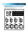
Panel cut dimension drawing (when used with the FR-A7CN)
200
40 102
90
90
90
FR-A7CN04
90
112
175
102
FR-A7CN03
175
102
FR-A7CN02
100
FR-A7CN01
195
195
145
212
212
FR-A7CN05
FR-A7CN06
FR-A7CN07
230
260
FR-A7CN08
290
410
470
265
380
440
270
270
330
330
660
108
690
582
4-M10 screw
13
615
590
4-M10 screw
15
12
12
6-M8 screw
510
85
540
95
611
516
600
70
516
105
298
279
4-M8 screw
12.5
440
335
6-M8 screw
40
136
586
517
320
6-M5 screw
7.5
407
305
280
6-M5 screw
7.5
367
265
280
6-M5 screw
7.5
365
265
244
380
400
440
477
(Unit: mm)
19
zWhen using a heatsink protrusion attachment (FR-A7CN)
470
470
440
440
440
Standard
Specifications
740
Peripheral
Devices
108
770
4-M10 screw
400
400
410
477
477
477
Outline
Dimension
Drawings
13
13
4-M10 screw
13
4-M10 screw
662
780
810
660
702
108
108
470
582
690
FR-A7CN11
Features
FR-A7CN10
Refer to page 79 for the correspondence table of the attachment and inverter.
(Unit: mm)
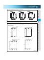
zProtrusion of heatsink of the FR-A740-160K or more
Operation
Panel
Panel cutting
Cut the panel of the enclosure according to the inverter capacity.
FR-A740-220K, 250K, 280K
6-M10 screw
6-M10 screw
662
200
300
300
Protective
Functions
Hole
FR-A740-315K, 355K
Instructions
15
18
Options
984
Hole
954
954
985
Explanations
of
Parameters
15
13
484
200
Parameter
List
FR-A740-160K, 185K
Terminal Connection
Diagram
Terminal Specification
Explanation
FR-A7CN09
FR-A740-400K, 450K, 500K
6-M10 screw
315
300
300
300
Compatibility
Hole
Inquiry
Warranty
1508
1550
Hole
21
1258
21
1300
21
Motor
315
8-M10 screw
976
21
771
(Unit: mm)
20
Shift and removal of a rear side installation frame
FR-A740-160K to 280K
One installation frame is attached to each of the upper
and lower part of the inverter. Change the position of
the rear side installation frame on the upper and lower
side of the inverter to the front side as shown on the
right. When changing the installation frames, make
sure that the installation orientation is correct.
FR-A740-315K or more
Two installation frames each are attached to the
upper and lower part of the inverter. Remove the
rear side installation frame on the upper and lower
side of the inverter as shown below.
Removal
Shift
Upper installation
frame (rear side)
Upper
installation
frame
Shift
Lower installation
frame (rear side)
Lower
installation
frame
Removal
Installation of the inverter
Push the inverter heatsink portion outside the enclosure and fix the enclosure and inverter with upper and lower
installation frame.
Enclosure
Inside the
enclosure Exhausted air
* For the FR-F740-220K or more, there are finger
*
guards behind the enclosure. Therefore, the
thickness of the panel should be less than 10mm
(*1) and also do not place anything around finger
guards to avoid contact with the finger guards.
Inverter
Enclosure
Installation
frame
1
140
Finger guard
6
10*
Dimension of
Cooling
wind the outside of
the enclosure
D1
Inverter Type
D1
FR-A740-160K, 185K
185
FR-A740-220K to 500K
184
(Unit: mm)
CAUTION
· Having a cooling fan, the cooling section which comes out of the enclosure can not be used in the environment of water
drops, oil, mist, dust, etc.
· Be careful not to drop screws, dust etc. into the inverter and cooling fan section.
21
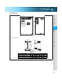
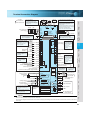
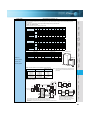
Terminal Connection Diagram
Low speed
Jog mode
Second function selection
Output stop
Reset
Terminal 4 input selection
(Current input selection)
Selection of automatic restart
after instantaneous
power failure
Contact input common
24VDC power supply
(Common for external power supply transistor)
Frequency setting signal (Analog)
1
B2
RM
Relay output 2
A2
RL
JOG *3
Open collector output
RUN
Running
RT
SU
MRS
IPF
RES *4
OL
AU
FU
AU
Terminal functions
Up to frequency vary with the output
terminal assignment
Instantaneous (Pr. 190 to Pr. 194)
power failure
(Refer to the
Instruction Manual
Overload
(applied))
Frequency detection
CS PTC
SD
SE
PC
0 to ±10VDC (Initial value)
0 to ±5VDC selected *5
Terminal 4 input (+)
(Current input) (-)
4
4 to 20mADC (Initial value)
0 to 5VDC selected *5
0 to 10VDC
Option connector 1
Option connector 2
Option connector 3
Open collector output common
Sink/source common
*10. It is not necessary
when calibrating the
indicator from the
operation panel.
PU
connector
+
USB
FM
connector *11 Calibration
SD resistor *10
AM
5
TXD+
TXD-
*11. FM terminal can
be used for pulse
train output of open
collector output
using Pr.291.
- Indicator
(Frequency meter, etc.)
Moving-coil type
1mA full-scale
(+) Analog signal output
(0 to 10VDC)
(-)
RS-485 terminals
Data transmission
RXD+
RXD-
Data reception
SG
GND
Terminating
resistor VCC
Features
Peripheral
Devices
Standard
Specifications
Outline
Dimension
Drawings
Terminal Connection
Diagram
Terminal Specification
Explanation
C2
RH
1
*6. It is recommended to use 2W1kΩ
when the frequency setting signal
is changed frequently.
Terminal functions
Relay output 1 vary with the output
(Alarm output) terminal assignment
(Pr. 195, Pr. 196)
(Refer to the
Instruction Manual
(applied))
A1
Auxiliary input (+)
(-)
Connector
for plug-in option
connection
B1
STOP
10(+5V)
0 to 5VDC (Initial value)
2 0 to 10VDC selected
*5
4 to 20mADC
5
(Analog common)
2
Relay output
STR
10E(+10V)
3
C1
STF
Operation
Panel
Middle
speed
*9.The FR-A720-0.4K and 0.75K
are not provided with the EMC
filter ON/OFF connector. (Always on)
Control circuit
SOURCE
Control input signals (No voltage input allowed)
Forward
Terminal functions vary with
rotation
the input terminal
start
assignment (Pr. 178 to Pr. 189) Reverse
rotation
(Refer to the Instruction
start
Manual (applied))
Start selfholding selection
High speed
*5. Terminal input specifications can
be changed by analog input
specifications switchover (Pr. 73,
Pr. 267) .
Earth (Ground)
Main circuit
Earth
(Ground)
Motor
IM
5V (Permissible load
current 100mA)
Parameter
List
OFF
U
V
W
EMC filter
ON/OFF
connecter *9
Explanations
of
Parameters
ON
Protective
Functions
*2
Frequency setting
potentiometer
1/2W1kΩ
*6
(Refer to the Instruction Manual)
R1/L11
S1/L21
Jumper
*4. AU terminal can be
used as PTC input
terminal.
N/- CN8
*7
Options
Three-phase AC
power supply
*3. JOG terminal can be used
as pulse train input terminal.
Use Pr.291 to select
JOG/pulse.
PR
R
R/L1
S/L2
T/L3
Multi-speed
selection
PX
*8. Brake resistor (FR-ABR)
Remove the jumper across terminal PR-PX
when connecting a brake resistor.
(0.4K to 7.5K)
Terminal PR is provided for the 0.4K to 22K.
Install a thermal relay to prevent an overheat
and burnout of the brake resistor.
Instructions
P/+
MC
*2. To supply power to the
control circuit separately,
remove the jumper across
R1/L11 and S1/L21.
Jumper
Jumper
Motor
*8
Earth
(Ground)
*7. A CN8 connector is provided with the 75K
or more.
Compatibility
R
P1
MCCB
Brake unit
(Option)
*1
Warranty
Control circuit terminal
*1. DC reactor (FR-HEL)
Be sure to connect the DC reactor
supplied with the 75K or more.
When a DC reactor is connected to
the 55K or less, remove the jumper
across P1-P/+.
SINK
Sink logic
Main circuit terminal
⋅ Be sure to earth (ground) the inverter and motor before use.
⋅ This connection diagram assumes that the control circuit is sink logic (initial setting). Refer to the instruction manual for the connection in the case of
Inquiry
CAUTION
⋅ To prevent a malfunction caused by noise, separate the signal cables more than 10cm from the power cables.
source logic.
22
Terminal Specification Explanation
Type
Terminal
Symbol
Terminal Name
R/L1, S/L2, T/L3 AC power input
U, V, W
Inverter output
R1/L11, S1/L21 Power supply for control
circuit
Main
circuit
P/+, PR
Brake resistor
connection
P/+, N/-
Brake unit connection
P/+, P1
DC reactor connection
PR, PX
Built-in brake circuit
connection
Connect to the commercial power supply.
Connect a three-phase squirrel-cage motor.
Connected to the AC power supply terminals R/L1 and S/L2. To retain alarm display and
alarm output, apply external power to this terminal.
Remove the jumper from terminals PR-PX (7.5K or less) and connect an optional brake
resistor (FR-ABR) across terminals P/+-PR. The PR terminal is provided for the 22K or
less.
Connect the brake unit (FR-BU and BU, MT-BU5), power regeneration common
converter (FR-CV) or regeneration common converter (MT-RC) and high power factor
converter (FR-HC, MT-HC).
For the 55K or less, remove the jumper across terminals P/+-P1 and connect a DC
reactor. (For the 75K or more, a DC reactor is supplied as standard.)
When the jumper is connected across terminals PX-PR (initial status), the built-in brake
circuit is valid. The PX terminal is provided for the 7.5K or less.
Earth (Ground)
For earthing (grounding) the inverter chassis. Must be earthed (grounded).
STF
Forward rotation start
STR
Reverse rotation start
Turn on the STF signal to start forward rotation and turn it off When the STF and STR
to stop.
signals are turned on
Turn on the STR signal to start reverse rotation and turn it off simultaneously, the stop
to stop.
command is given.
STOP
RH, RM, RL
Start self-holding
selection
Multi-speed selection
Jog mode selection
JOG
Pulse train input
Contact input
RT
Second function
selection
MRS
Output stop
RES
Reset
AU
Terminal 4 input
selection
Control circuit/input signal
PTC input
CS
Selection of automatic
restart after
instantaneous power
failure
SD
Contact input common
(sink)
PC
External transistor
common,
24VDC power supply,
contact input common
(source)
10E
Frequency setting
10
23
Description
Frequency setting
power supply
2
Frequency setting
(voltage)
4
Frequency setting
(current)
1
Frequency setting
auxiliary
5
Frequency setting
common
Turn on the STOP signal to self-hold the start signal.
Multi-speed can be selected according to the combination of RH, RM and RL signals.
Turn on the JOG signal to select Jog operation (initial setting) and turn on the start
signal (STF or STR) to start Jog operation.
JOG terminal can be used as pulse train input terminal. To use as pulse train input
terminal, the Pr.291 setting needs to be changed. (maximum input pulse: 100kpulses/s)
Turn on the RT signal to select second function selection
When the second function such as “Second torque boost” and “Second V/F (base
frequency)” are set, turning on the RT signal selects these functions.
Turn on the MRS signal (20ms or more) to stop the inverter output.
Use to shut off the inverter output when stopping the motor by electromagnetic brake.
Used to reset alarm output provided when protective function is activated. Turn on the RES
signal for more than 0.1s, then turn it off. Recover about 1s after reset is cancelled.
Terminal 4 is made valid only when the AU signal is turned on.
Turning the AU signal on makes terminal 2 invalid.
AU terminal is used as PTC input terminal (thermal protection of the motor). When using
it as PTC input terminal, set the AU/PTC switch to PTC.
When the CS signal is left on, the inverter restarts automatically at power restoration.
Note that restart setting is necessary for this operation. In the initial setting, a restart is
disabled.
Common terminal for contact input terminal (sink logic) and terminal FM. Common
output terminal for 24VDC 0.1A power supply (PC terminal). Isolated from terminals 5
and SE.
When connecting the transistor output (open collector output), such as a programmable
controller (PLC), when sink logic is selected, connect the external power supply
common for transistor output to this terminal to prevent a malfunction caused by
undesirable currents. Can be used as 24VDC 0.1A power supply. When source logic
has been selected, this terminal serves as a contact input common.
10VDC, permissible load
When connecting a frequency setting potentiometer at an
current 10mA
initial status, connect it to terminal 10.
Change the input specifications of terminal 2 when
5VDC, permissible load
connecting it to terminal 10E.
current 10mA
Inputting 0 to 5VDC (or 0 to 10V, 4 to 20mA) provides the maximum output frequency at
5V (10V, 20mA) and makes input and output proportional. Use Pr.73 to switch from
among input 0 to 5VDC (initial setting), 0 to 10VDC, and 4 to 20mA.
Voltage input: Input resistance 10kΩ ±1kΩ Maximum permissible voltage 20VDC
Current input: Input resistance 250Ω ±5Ω (When power is ON)
Maximum permissible current 30mA
Input resistance 10kΩ ±1kΩ (When power is OFF)
Inputting 4 to 20mADC (or 0 to 5V, 0 to 10V) provides the maximum output frequency at
20mA and makes input and output proportional. This input signal is valid only when the
AU signal is on (terminal 2 input is invalid). Use Pr.267 to switch from among input 4 to
20mA (initial setting), 0 to 5VDC, and 0 to 10VDC.
Voltage input: Input resistance 10kΩ ±1kΩ Maximum permissible voltage 20VDC
Current input: Input resistance 250Ω ±5Ω (When power is ON)
Maximum permissible current 30mA
Input resistance 10kΩ ±1kΩ (When power is OFF)
Inputting 0 to ±5VDC or 0 to ±10VDC adds this signal to terminal 2 or 4 frequency
setting signal. Use Pr.73 to switch between input 0 to ±5VDC and 0 to ±10VDC (initial
setting) input.
Input resistance 10kΩ ±1kΩ Maximum permissible voltage ±20VDC
Common terminal for frequency setting signal (terminal 2, 1 or 4) and analog output terminal
AM. Do not earth (ground)
FU
Frequency detection
SE
Open collector output
common
Pulse
For meter
FM
Communication
Analog
Open collector output
AM
Analog signal output
PU connector
RS-485
terminals
TXD+,
TXDRXD+,
RXDSG
Inverter transmission
terminal
Inverter reception
terminal
Earth (Ground)
USB connector
Common terminal for terminals RUN, SU, OL, IPF, FU
Output item: output frequency (initial
setting),
permissible load current 2mA,
1440 pulses/s at 60Hz
Select one e.g. output frequency from
Signals can be output from the open collector
monitor items.*2
terminals by setting Pr.291. (maximum output
The output signal is proportional to the
pulse: 50kpulses/s)
magnitude of the corresponding
Output item: output frequency (initial
monitoring item.
setting),
output signal 0 to 10VDC,
permissible load current 1mA(load impedance
10kΩ or more),
resolution 8 bit
With the PU connector, communication can be made through RS-485. (1:1 connection
only)
⋅ Conforming standard: EIA-485(RS-485) ⋅ Communication speed: 4800 to 38400bps
⋅ Transmission format: Multi-drop link
⋅ Overall extension: 500m
With the RS-485 terminals, communication can be made through RS-485.
Features
Instantaneous power
failure
Peripheral
Devices
IPF
Standard
Specifications
Overload alarm
Outline
Dimension
Drawings
OL
Terminal Connection
Diagram
Terminal Specification
Explanation
Up to frequency
Operation
Panel
SU
Parameter
List
Inverter running
Explanations
of
Parameters
RUN
Protective
Functions
Relay output 2
⋅ Conforming standard: EIA-485(RS-485) ⋅ Communication speed: 300 to 38400bps
⋅ Transmission format: Multi-drop link
⋅ Overall extension: 500m
The FR-Configurator can be operated by connecting the inverter to the personnel
computer through USB.
⋅ Interface: conforms to USB1.1
⋅ Connector: USB series B connector
⋅ Transfer rate: FS transfer (12Mbps)
CAUTION
⋅ The inverter will be damaged if power is applied to the inverter output terminals (U, V, W). Never perform such wiring.
⋅
indicates that terminal functions can be selected from Pr.178 to Pr.196 (I/O terminal function selection).
⋅ Terminal names and terminal functions are those of the factory set.
*1 Low indicates that the open collector output transistor is on (conducts). High indicates that the transistor is off (does not conduct).
*2 Not output during inverter reset.
Options
A2, B2, C2
1 changeover contact output indicates that the inverter protective function has activated and
the output stopped. Alarm: discontinuity across B-C (continuity across A-C), Normal:
continuity across B-C (discontinuity across A-C) Contact capacity 230VAC 0.3A (power
factor =0.4) 30VDC 0.3A
1 changeover contact output, contact capacity 230VAC, 0.3A (power factor=0.4) 30VDC
0.3A
Switched low when the inverter output frequency is equal to or
higher than the starting frequency (initial value 0.5Hz).
Switched high during stop or DC injection brake operation.*1
Switched low when the output frequency
reaches within the range of ±10% (initial value)
of the set frequency. Switched high during
acceleration/deceleration and at a stop.*1
Permissible load 24VDC
Switched low when stall prevention is
0.1A
activated by the stall prevention function.
Alarm code (4bit) (a voltage drop is 2.8V
Switched high when stall prevention is
maximum when the
cancelled.*1
output
Switched low when an instantaneous
(Refer to page 53.) signal is on)
power failure and under voltage
protections are activated.*1
Switched low when the inverter output
frequency is equal to or higher than the
preset detected frequency and high when
less than the preset detected frequency.*1
Instructions
Relay output 1 (alarm
output)
Motor
A1, B1, C1
Description
Compatibility
Terminal Name
Warranty
Terminal
Symbol
Inquiry
Open collector
Control circuit/input signal
Relay
Type
24
Wiring example
Standard motor with encoder (SF-JR), 5V differential line driver (speed control)
Sink logic
Main circuit terminal
Control circuit terminal
Jumper
P1
MCCB
Jumper
P/+
PX
PR
R
MC
U
V
W
R/L1
S/L2
T/L3
Three-phase AC
power supply
Jumper
SF-JR motor
with encoder
N/-
R1/L11
S1/L21
Control circuit
Forward rotation start
High speed
Middle speed
Low speed
Jog mode
Second function selection
Output stop
Reset
RUN
STR
SU
STOP
IPF
RH
OL
RM
FU
RL
SE
Frequency
detection
Open collector
output common
C1
Relay output
RT
CS
1
Overload
Relay output 1
(alarm output)
Relay output 2
A2
SD
FR-A7AP
PA1
C
PA2
R
PB1
A
PB2
N
PZ1
PZ2
B
PG
H
SD
K
10(+5V)
0 to 5VDC (Initial value)
2 0 to 10VDC selected
4 to 20mADC
5 (Analog common)
0 to ±10VDC (Initial value)
1
0 to ±5VDC selected
Encoder
P
PG
SD
*
(+)
(-) 5VDC power supply
Complimentary
ON
Terminating
resistor
OFF
25
Instantaneous
power failure
C2
Differential line driver
(+)
torque limit command
(-)
( 10V)
Up to frequency
B2
10E(+10V)
2
A1
RES
Selection of automatic restart
after instantaneous power failure
Contact input common
3
B1
MRS
AU
Frequency setting
potentiometer
1/2W1kΩ
Running
JOG
Terminal 4 input selection
(current input selection)
Analog input
Open collector
output
STF
Reverse rotation start
Start self-holding selection
IM
Earth
(ground)
Main circuit
Control input signals (no voltage input allowed)
U
V
W
E
*. Earth the shield cable of the encoder
cable to the enclosure with a P clip, etc.
MCCB
SF-V5RU
A
B
C
Forward rotation start
Reverse rotation start
Contact input common
Speed limit command
Frequency setting potentiometer
1/2W1kΩ
2
G2
A
PB1
C
PB2
D
Differential
line driver PZ1
PZ2
G
5
Complimentary PG
Terminating SD
R
resistor
Torque
(+)
command
(-)
(±10V)
1
ON
*6
OFF
Position control
*3
Encoer
F
2
1
Thermal
protector
G1
2W1kΩ
B
10
3
Earth
(ground)
PA2
SD
IM
*4
S
PG
SD
*5
*8
(+)
12VDC
(-) power supply *7
MCCB
SF-V5RU
*1
A
B
C
Three-phase AC
power supply
U
V
W
E
IM
Earth
(ground)
Pre-excitation/servo on
Clear signal
CLEAR
Pulse train
PULSE F
Sign signal
24VDC power supply
PULSE R
PB1
C
PB2
D
PC
PULSE COM
SE
RDY COM
COM
Torque limit command (+)
(±10V) (-)
A
Differential
line driver PZ1
PZ2
F
G
resistor
ON
Encoder
*4
S
Complimentary PG
Terminating SD
RDY *11
5
*3
B
JOG *10
CLEAR COM
Preparation ready signal
G2
CLR *9
NP *9
Protective
Functions
Forward stroke end
Reverse stroke end
Thermal
protector
G1
Options
STOP
External thermal PC
relay input *2CS(OH) 2W1kΩ
SD
STF
FR-A7AP
STR
PA1
LX *9
PA2
R
PG
SD
*6 *8
OFF
*5
(+)
12VDC
(-) power supply *7
Motor
DOG
Instructions
U
V
W
Inverter
1
*1
For the fan of the 7.5kW or less dedicated motor, the power supply is single phase (200V/50Hz, 200 to 230V/60Hz).
*2
Assign OH (external thermal input) signal to the terminal CS. (Set "7" in Pr. 186.)
Connect a 2WlkΩ resistor between the terminal PC and CS (CH). Install the resistor pushing it against the bottom
CS(OH)
PC
Control circuit
terminal block
part of the terminal block so as to avoid a contact with other cables.
*4
*5
Connect the encoder so that there is no looseness between the motor and motor shaft. Speed ratio should be 1:1.
Earth the shield cable of the encoder cable to the enclosure with a P clip, etc.
*6
*7
For the complementary, set the switch to off position.
A separate power supply of 5V/12V/15V/24V is necessary according to the encoder power specification.
*8
*9
For terminal compatibility of the FR-JCBL, FR-V5CBL and FR-A7AP, refer to the inverter manual or the instruction manual of the FR-A7AP.
Assign the function using Pr.178 to Pr.184, Pr.187 to Pr.189 (input terminal function selection).
Warranty
*3
Refer to the inverter manual for details of Pr. 186 CS terminal function selection.
The pin number differs according to the encoder used.
Compatibility
R/L1
S/L2
T/L3
Explanations
of
Parameters
MCCB
Three-phase AC
power supply
FLS
RLS
READY
FAN
Resistor (2W1kΩ)
*10 When position control is selected, terminal JOG function is made invalid and conditional position pulse train input terminal becomes valid.
*11 Assign the function using Pr.190 to Pr.194 (output terminal function selection).
Inquiry
Positioning unit
MELSEQ-Q QD75P1
Outline
Dimension
Drawings
R/L1
S/L2 External thermal
T/L3 relay input *2 PC
CS(OH)
SD
STF
FR-A7AP
STR
PA1
Three-phase AC
power supply
U
V
W
E
Terminal Connection
Diagram
Terminal Specification
Explanation
MCCB
U
V
W
Operation
Panel
Inverter
FAN
Peripheral
Devices
Three-phase AC
power supply
Standard
Specifications
*1
Parameter
List
Torque control
Features
Vector control dedicated motor (SF-V5RU), 12V complimentary
26
Operation Panel (FR-DU07)
Operation mode indication
PU: Lit to indicate PU operation mode.
EXT: Lit to indicate external operation mode.
NET: Lit to indicate network operation mode.
Rotation direction indication
FWD: Lit during forward rotation
REV: Lit during reverse rotation
On:
Forward/reverse operation
Flickering: When the frequency command is
not given even if the
forward/reverse command is given.
Unit indication
· Hz: Lit to indicate frequency.
· A: Lit to indicate current.
· V: Lit to indicate voltage.
(Flicker when the set frequency monitor is
displayed.)
Monitor indication
Lit to indicate monitoring mode.
No function
Monitor(4-digit LED)
Shows the frequency, parameter
number, etc.
Start command
forward rotation
Start command
reverse rotation
Setting dial
(Setting dial: Mitsubishi inverter
dial)
Stop operation
Alarms can be reset
Used to change the
frequency setting and
parameter values.
Used to set each setting.
If pressed during operation, monitor
changes as below;
Mode
switchover
Used to change
each setting mode.
Running
frequency
Output
current
Output
voltage
* Energy saving monitor is displayed when the
energy saving monitor of Pr. 52 is set.
Operation mode switchover
Used to switch between the PU and external operation mode.
When using the external operation mode (operation using a separately
connected frequency setting potentiometer and start signal), press this key to
light up the EXT indication. (Change the Pr.79 value to use the combined mode.)
PU: PU operation mode
EXT: External operation mode
27
*
Features
Basic operation
Operation mode switchover
and frequency flicker.
Frequency setting has been
written and completed!!
Output current monitor
Output voltage monitor
Terminal Connection
Diagram
Terminal Specification
Explanation
Value change
PU operation mode
(output frequency monitor)
Operation
Panel
(Example)
Explanations
of
Parameters
(Example)
Value change
Compatibility
[Operation for displaying alarm history]
Past eight alarms can be displayed.
(The latest alarm is ended by ".".)
When no alarm history exists,
is displayed.
Warranty
Alarm history
Parameter copy
Instructions
Alarm clear
Motor
Parameter
all clear
Options
Parameter and a setting value
flicker alternately.
Parameter write is completed!!
Parameter clear
Protective
Functions
Display the current
setting
Parameter setting mode
Inquiry
Parameter setting
Parameter
List
Monitor/frequency setting
PU Jog operation mode
Outline
Dimension
Drawings
Standard
Specifications
Peripheral
Devices
At powering on (external operation mode)
28
Parameter List
For simple variable-speed operation of the inverter, the initial setting of the parameters may be used as they are. Set the
necessary parameters to meet the load and operational specifications. Parameter setting, change and check can be made
from the operation panel (FR-DU07). For details of parameters, refer to the instruction manual.
REMARKS
⋅
⋅
indicates simple mode parameters. (initially set to extended mode)
The shaded parameters in the table allow its setting to be changed during operation even if "0" (initial value) is set in Pr.77 Parameter write
selection.
Basic functions
Function
Parameter
Setting Range
Minimum
Setting
Increments
Initial Value
Refer
to
Page
0.1%
6/4/3/2/1% *1
42
120/60Hz
42
0
Torque boost
0 to 30%
1
Maximum frequency
0 to 120Hz
0.01Hz
2
Minimum frequency
0 to 120Hz
0.01Hz
0Hz
42
3
Base frequency
0 to 400Hz
0.01Hz
60Hz
42
4
Multi-speed setting (high speed)
0 to 400Hz
0.01Hz
60Hz
42
5
Multi-speed setting (middle speed)
0 to 400Hz
0.01Hz
30Hz
42
6
Multi-speed setting (low speed)
0 to 400Hz
0.01Hz
10Hz
42
7
Acceleration time
0 to 3600/360s
0.1/0.01s
5/15s *3
43
8
Deceleration time
0 to 3600/360s
0.1/0.01s
5/15s *3
43
0.01/0.1A *2
Inverter
rated output
current
43
0 to 500/0 to 3600A *2
10
DC injection brake operation frequency 0 to 120Hz, 9999
0.01Hz
3Hz
43
11
DC injection brake operation time
0 to 10s, 8888
0.1s
0.5s
43
12
DC injection brake operation voltage
0 to 30%
0.1%
4/2/1%*3
43
13
14
Starting frequency
Load pattern selection
0 to 60Hz
0 to 5
0.01Hz
1
0.5Hz
0
43
44
15
Jog frequency
0 to 400Hz
0.01Hz
5Hz
44
16
Jog acceleration/deceleration time
0 to 3600/360s
0.1/0.01s
0.5s
44
17
18
19
MRS input selection
High speed maximum frequency
Base frequency voltage
0, 2
120 to 400Hz
0 to 1000V, 8888, 9999
1
0.01Hz
0.1V
20
Acceleration/deceleration reference
frequency
1 to 400Hz
0.01Hz
60Hz
43
21
Acceleration/deceleration time
increments
0, 1
1
0
43
22
Stall prevention operation level
(torque limit level )
0 to 400%
0.1%
150%
44, 45
23
Stall prevention operation level
compensation factor at double speed
0 to 200%, 9999
0.1%
9999
44
24 to 27
Multi-speed setting(4 speed to 7 speed)
0 to 400Hz, 9999
0.01Hz
9999
42
28
0, 1
1
0
45
29
Multi-speed input compensation selection
Acceleration/deceleration pattern
selection
0 to 5
1
0
46
30
31
32
33
34
35
36
37
41
42
Regenerative function selection
Frequency jump 1A
Frequency jump 1B
Frequency jump 2A
Frequency jump 2B
Frequency jump 3A
Frequency jump 3B
Speed display
Up-to-frequency sensitivity
Output frequency detection
0, 1, 2, 10, 11, 12, 20, 21
0 to 400Hz, 9999
0 to 400Hz, 9999
0 to 400Hz, 9999
0 to 400Hz, 9999
0 to 400Hz, 9999
0 to 400Hz, 9999
0, 1 to 9998
0 to 100%
0 to 400Hz
1
0.01Hz
0.01Hz
0.01Hz
0.01Hz
0.01Hz
0.01Hz
1
0.1%
0.01Hz
0
9999
9999
9999
9999
9999
9999
0
10%
6Hz
46
47
47
47
47
47
47
47
47
47
43
Output frequency detection for reverse
rotation
0 to 400Hz, 9999
0.01Hz
9999
47
Frequency
jump
Acceleration/
Multi-speed
Stall
deceleration
setting
prevention
times
DC injection
brake
Electronic thermal O/L relay
*2
Jog
operation
9
Frequency
detection
29
Name
0
120/60Hz
9999
*2
44
42
42
Customer
Setting
Second electronic thermal O/L relay
52
DU/PU main display data selection
54
FM terminal function selection
55
Frequency monitoring reference
0 to 500A, 9999/
0 to 3600A, 9999 *2
0, 5 to 14, 17 to 20,
22 to 25, 32 to 35,
50 to 57, 100
1 to 3, 5 to 14, 17, 18,
21, 24, 32 to 34, 50, 52,
53
0 to 400Hz
150%
44
0.01Hz
0Hz
44
0.01Hz
30Hz
47
9999
43
1
0
48
1
1
48
0.01Hz
60Hz
48
0.01/0.1A
Inverter
rated output
current
48
0.01/0.1A
*2
Current monitoring reference
0 to 500/0 to 3600A *2
57
Restart coasting time
0, 0.1 to 5s, 9999/
0, 0.1 to 30s, 9999 *2
0.1s
9999
49
58
Restart cushion time
0 to 60s
0.1s
1s
49
59
Remote function selection
0, 1, 2, 3
1
0
50
60
Energy saving control selection
0, 4
1
0
50
61
Reference current
0 to 500A, 9999/
0 to 3600A, 9999 *2
0.01A/0.1A *2
9999
50
62
Reference value at acceleration
0 to 220%, 9999
0.1%
9999
50
63
Reference value at dcceleration
0 to 220%, 9999
0.1%
9999
50
64
Starting frequency for elevator mode
0 to 10Hz, 9999
0.01Hz
9999
50
65
Retry selection
0 to 5
1
0
51
66
Stall prevention operation reduction
starting frequency
0 to 400Hz
0.01Hz
60Hz
44
67
Number of retries at alarm occurrence
0 to 10, 101 to 110
1
0
51
68
Retry waiting time
0 to 10s
0.1s
1s
51
69
Retry count display erase
0
1
0
51
70
Special regenerative brake duty
0 to 30%/0 to 10% *2
0.1%
0%
46
1
0
51
Automatic restart
56
*2
71
Applied motor
0 to 8, 13 to 18, 20, 23,
24, 30, 33, 34, 40, 43, 44,
50, 53, 54
72
PWM frequency selection
0 to 15/0 to 6, 25 *2
1
2
52
73
Analog input selection
0 to 7, 10 to 17
1
1
52
74
0 to 8
1
1
52
75
Input filter time constant
Reset selection/disconnected PU
detection/PU stop selection
0 to 3, 14 to 17
1
14
53
76
Alarm code output selection
0, 1, 2
1
0
53
77
Parameter write selection
0, 1, 2
1
0
53
78
Reverse rotation prevention selection
0, 1, 2
1
0
53
Operation mode selection
0, 1, 2, 3, 4, 6, 7
1
0
54
79
Features
Peripheral
Devices
0.1%
Automatic acceleration/
deceleration
51
0 to 400Hz
42
Standard
Specifications
Second output frequency detection
0 to 400Hz, 9999
42
9999
Retry
Monitor functions
50
0 to 220%
9999
Outline
Dimension
Drawings
48
Second stall prevention operation
current
Second stall prevention operation
frequency
0.1%
0.01Hz
Terminal Connection
Diagram
Terminal Specification
Explanation
0 to 400Hz, 9999
43
Operation
Panel
0 to 30%, 9999
Second V/F (base frequency)
43
9999
Parameter
List
Second torque boost
47
5s
0.1/0.01s
Explanations
of
Parameters
46
0.1/0.01s
Customer
Setting
Protective
Functions
0 to 3600/360s, 9999
Refer
to
Page
Options
0 to 3600/360s
Second deceleration time
Initial Value
Instructions
Second acceleration/deceleration time
45
Minimum
Setting
Increments
Motor
44
49
Setting Range
Compatibility
Name
Warranty
Parameter
Inquiry
Second functions
Function
30
Motor constants
Function
Parameter
Name
Setting Range
Minimum
Setting
Increments
Initial Value
Refer
to
Page
0.01/0.1kW *2
9999
55
1
9999
55
9999
55
80
Motor capacity
0.4 to 55kW, 9999/
0 to 3600kW, 9999 *2
81
Number of motor poles
2, 4, 6, 12, 14, 16, 9999
82
Motor excitation current
0 to 500A, 9999/
0 to 3600A, 9999 *2
83
Motor rated voltage
0 to 1000V
0.1V
200/400V
55
84
Rated motor frequency
10 to 120Hz
0.01Hz
60Hz
55
89
Speed control gain (magnetic flux vector)
0 to 200%
0.1%
9999
55
90
Motor constant (R1)
0 to 50Ω, 9999/
0 to 400mΩ, 9999 *2
9999
55
91
Motor constant (R2)
0 to 50Ω, 9999/
0 to 400mΩ, 9999 *2
9999
55
92
Motor constant (L1)
0 to 50Ω (0 to 1000mH), 9999/
0 to 3600mΩ (0 to 400mH), 9999 *2
9999
55
9999
55
9999
55
93
0.01/0.1A
*2
0.001Ω/
0.01mΩ *2
0.001Ω/
0.01mΩ *2
0.001Ω (0.1mH)/
0.01mΩ(0.01mH)
*2
0.001Ω (0.1mH)/
Motor constant (L2)
0 to 50Ω (0 to 1000mH), 9999/
0 to 3600mΩ (0 to 400mH), 9999 *2 0.01mΩ(0.01mH)
*2
PU connector
communication
Third functions
Adjustable 5 points V/F
94
0 to 500Ω (0 to 100%), 9999/
0 to 100Ω (0 to 100%), 9999 *2
0.01Ω (0.1%)/
0.01Ω (0.01%)
*2
95
Online auto tuning selection
0 to 2
1
0
56
96
Auto tuning setting/status
0, 1, 101
1
0
55
100
V/F1(first frequency)
0 to 400Hz, 9999
0.01Hz
9999
56
101
V/F1(first frequency voltage)
0 to 1,000V
0.1V
0V
56
102
V/F2(second frequency)
0 to 400Hz, 9999
0.01Hz
9999
56
103
V/F2(second frequency voltage)
0 to 1,000V
0.1V
0V
56
104
V/F3(third frequency)
0 to 400Hz, 9999
0.01Hz
9999
56
105
V/F3(third frequency voltage)
0 to 1,000V
0.1V
0V
56
106
V/F4(fourth frequency)
0 to 400Hz, 9999
0.01Hz
9999
56
107
V/F4(fourth frequency voltage)
0 to 1,000V
0.1V
0V
56
108
V/F5(fifth frequency)
0 to 400Hz, 9999
0.01Hz
9999
56
109
V/F5(fifth frequency voltage)
0 to 1,000V
0.1V
0V
56
110
Third acceleration/deceleration time
0 to 3600/360s, 9999
0.1/0.01s
9999
43
0.1/0.01s
9999
43
0.1%
9999
42
0.01Hz
9999
42
0.1%
150%
44
111
Third deceleration time
0 to 3600/360s, 9999
112
Third torque boost
0 to 30%, 9999
113
Third V/F (base frequency)
0 to 400Hz, 9999
114
Third stall prevention operation current 0 to 220%
115
Thrid stall prevention operation
frequency
0 to 400Hz
0.01Hz
0
44
116
Third output frequency detection
0 to 400Hz
0.01Hz
60Hz
47
117
PU communication station
0 to 31
1
0
56
118
PU communication speed
48, 96, 192, 384
1
192
56
119
PU communication stop bit length
0, 1, 10, 11
1
1
56
120
PU communication parity check
0, 1, 2
1
2
56
121
Number of PU communication retries
0 to10, 9999
122
PU communication check time interval
0, 0.1 to 999.8s, 9999
123
PU communication waiting time setting 0 to 150ms, 9999
124
31
Motor constant (X)
125
126
PU communication CR/LF presence/
absence selection
Terminal 2 frequency setting gain
frequency
Terminal 4 frequency setting gain
frequency
1
1
56
0.1s
9999
56
1
9999
56
1
1
56
0 to 400Hz
0.01Hz
60Hz
57
0 to 400Hz
0.01Hz
60Hz
57
0, 1, 2
Customer
Setting
130
PID integral time
0.1 to 3600s, 9999
0.1s
1s
58
131
PID upper limit
0 to 100%, 9999
0.1%
9999
58
132
PID lower limit
0 to 100%, 9999
0.1%
9999
58
133
PID action set point
0 to 100%, 9999
0.01%
9999
58
134
PID differential time
0.01 to 10.00s, 9999
0.01s
9999
58
135
Commercial power-supply switchover
sequence output terminal selection
0, 1
1
0
58
136
MC switchover interlock time
0 to 100s
0.1s
1s
58
137
Start waiting time
0 to 100s
0.1s
0.5s
58
1
0
58
0 to 60Hz, 9999
0.01Hz
9999
58
0 to 400Hz
0.01Hz
1Hz
46
0.1s
0.5s
46
0.01Hz
1Hz
46
138
139
Commercial power-supply operation
switchover selection at an alarm
Automatic switchover frequency
between inverter and commercial
power-supply operation
Backlash acceleration stopping
frequency
0, 1
Backlash acceleration stopping time
0 to 360s
142
Backlash deceleration stopping
frequency
0 to 400Hz
143
Backlash deceleration stopping time
0 to 360s
0.1s
0.5s
46
1
4
47
144
Speed setting switchover
145
PU display language selection
0 to 7
1
0
58
148
Stall prevention level at 0V input
0 to 220%
0.1%
150%
44
149
Stall prevention level at 10V input
0 to 220%
0.1%
200%
44
150
Output current detection level
0 to 220%
0.1%
150%
58
151
Output current detection signal delay
time
0 to 10s
0.1s
0s
58
152
Zero current detection level
0 to 220%
0.1%
5%
58
153
Zero current detection time
0 to 1s
0.01s
0.5s
58
154
Voltage reduction selection during stall
prevention operation
0, 1
1
1
44
155
RT signal reflection time selection
0, 10
1
0
59
156
Stall prevention operation selection
0 to 31, 100, 101
157
OL signal output timer
0 to 25s, 9999
158
AM terminal function selection
1 to 3, 5 to 14, 17, 18,
21, 24, 32 to 34, 50,
52, 53
159
Automatic switchover ON range
between commercial power-supply and
inverter operation
0 to 10Hz, 9999
User group read selection
Current detection
0, 2, 4, 6, 8, 10, 102,
104, 106, 108, 110
PU
141
160
161
162
Current detection
Automatic restart
functions
Frequency setting/key lock operation
selection
Automatic restart after instantaneous
power failure selection
1
0
44
0.1s
0s
44
1
1
48
0.01Hz
9999
58
0, 1, 9999
1
0
59
0, 1, 10, 11
1
0
59
0, 1, 2, 10, 11, 12
1
0
49
163
First cushion time for restart
0 to 20s
0.1s
0s
49
164
First cushion voltage for restart
0 to 100%
0.1%
0%
49
165
Stall prevention operation level for
restart
0 to 220%
0.1%
150%
49
166
Output current detection signal
retention time
0 to 10s, 9999
0.1s
0.1s
58
167
Output current detection operation
selection
0, 1
1
0
58
Features
58
0.1 to 1000%, 9999
Peripheral
Devices
100%
PID proportional band
Standard
Specifications
0.1%
129
Outline
Dimension
Drawings
58
10, 11, 20, 21, 50, 51, 60,
61
Terminal Connection
Diagram
Terminal Specification
Explanation
10
PID action selection
Operation
Panel
1
128
Parameter
List
58
Explanations
of
Parameters
9999
0 to 400Hz, 9999
Protective
Functions
0.01Hz
PID control automatic switchover
freqeuncy
Customer
Setting
Options
Refer
to
Page
Instructions
Initial Value
Motor
Minimum
Setting
Increments
Compatibility
Setting Range
127
140
Backlash
measures
Name
Warranty
Parameter
Inquiry
Commercial power supplyinverter switch-over
PID operation
Function
32
Parameter
168
169
33
Name
Setting Range
Minimum
Setting
Increments
Initial Value
Refer
to
Page
Parameter for manufacturer setting. Do not set.
170
Watt-hour meter clear
0, 10, 9999
1
9999
48
171
Operation hour meter clear
0, 9999
1
9999
48
172
User group registered display/batch
clear
9999, (0 to 16)
1
0
59
173
User group registration
0 to 999, 9999
1
9999
59
174
User group clear
0 to 999, 9999
1
9999
59
1
60
60
1
61
60
1
0
60
1
1
60
1
2
60
1
3
60
1
4
60
1
5
60
1
6
60
1
24
60
1
25
60
1
62
60
1
0
60
1
1
60
1
2
60
1
3
60
1
4
60
1
99
60
1
9999
60
0.01Hz
9999
42
178
STF terminal function selection
179
STR terminal function selection
180
RL terminal function selection
181
RM terminal function selection
182
RH terminal function selection
183
RT terminal function selection
0 to 20, 22 to 28, 42 to
44, 60, 62, 64 to 71,
9999
0 to 20, 22 to 28, 42 to
44, 61, 62, 64 to 71, 9999
0 to 20, 22 to 28, 42 to
44, 62, 64 to 71, 9999
0 to 20, 22 to 28, 42 to
44, 62 to 71, 9999
184
AU terminal function selection
185
JOG terminal function selection
186
CS terminal function selection
187
MRS terminal function selection
188
STOP terminal function selection
189
RES terminal function selection
190
RUN terminal function selection
191
SU terminal function selection
192
IPF terminal function selection
193
OL terminal function selection
194
FU terminal function selection
195
ABC1 terminal function selection
196
ABC2 terminal function selection
Multi-speed setting(8 speed to 15
speed)
0 to 400Hz, 9999
0 to 20, 22 to 28, 42 to
44, 62, 64 to 71, 9999
0 to 8, 10 to 20, 25 to 28,
30 to 36, 39, 41 to 47, 64,
70, 84, 85, 90 to 99,
100 to 108, 110 to 116,
120, 125 to 128, 130 to
136, 139, 141 to 147,
164, 170, 184, 185, 190
to 199, 9999
0 to 8, 10 to 20, 25 to 28,
30 to 36, 39, 41 to 47, 64,
70, 84, 85, 90, 91, 94 to
99,
100 to 108, 110 to 116,
120, 125 to 128, 130 to
136, 139, 141 to 147,
164, 170, 184, 185, 190,
191, 194 to 199, 9999
Multi-speed
setting
Output terminal function assignment
input terminal function assignment
User group
Cumulative monitor
clear
Function
232 to 239
240
Soft-PWM operation selection
0, 1
1
1
52
241
Analog input display unit switchover
0, 1
1
0
57
0 to 100%
0.1%
100%
52
0 to 100%
0.1%
75%
52
1
1
61
242
243
244
Terminal 1 added compensation
amount (terminal 2)
Terminal 1 added compensation
amount (terminal 4)
Cooling fan operation selection
0, 1
Customer
Setting
0, 9999
1
9999
61
250
Stop selection
0 to 100s,1000 to 1100s
8888, 9999
0.1s
9999
61
251
Output phase failure protection
selection
0, 1
1
1
61
252
Override bias
0 to 200%
0.1%
50%
52
253
Override gain
0 to 200%
0.1%
150%
52
255
Life alarm status display
(0 to 15)
1
0
61
256
Inrush current limit circuit life display
(0 to 100%)
1%
100%
61
257
Control circuit capacitor life display
(0 to 100%)
1%
100%
61
258
Main circuit capacitor life display
(0 to 100%)
1%
100%
61
259
Main circuit capacitor life measuring
0, 1
1
0
61
261
Power failure stop selection
0, 1, 2, 11, 12
1
0
62
262
Subtracted frequency at deceleration
start
0 to 20Hz
0.01Hz
3Hz
62
263
Subtraction starting frequency
0 to 120Hz, 9999
0.01Hz
60Hz
62
264
Power-failure deceleration time 1
0 to 3600/360s
0.1/0.01s
5s
62
265
Power-failure deceleration time 2
0 to 3600s/360s,
9999
0.1/0.01s
9999
62
266
Power failure deceleration time
switchover frequency
0 to 400Hz
0.01Hz
60Hz
62
267
Terminal 4 input selection
0, 1, 2
1
0
52
268
Monitor decimal digits selection
0,1, 9999
1
9999
48
269
Parameter for manufacturer setting. Do not set.
270
Stop-on contact/load torque highspeed frequency control selection
0, 1, 2, 3
1
0
63
Stop-on contact
Load torque
control
high speed frequency control
271
High-speed setting maximum current
0 to 220%
0.1%
50%
63
272
Middle-speed setting minimum current
0 to 220%
0.1%
100%
63
273
Current averaging range
0 to 400Hz, 9999
0.01Hz
9999
63
274
Current averaging filter time constant
1 to 4000
1
16
63
275
Stop-on contact excitation current lowspeed multiplying factor
0 to 1000%, 9999
0.1%
9999
63
276
PWM carrier frequency at stop-on
contact
0 to 9, 9999/
0 to 4, 9999 *2
1
9999
63
Power failure stop
Life check
Frequency compensation
function
Features
Constant-power region slip
compensation selection
Peripheral
Devices
247
Standard
Specifications
61
Outline
Dimension
Drawings
0.5s
Terminal Connection
Diagram
Terminal Specification
Explanation
0.01s
Operation
Panel
0.01 to 10s
Parameter
List
Slip compensation time constant
246
Explanations
of
Parameters
61
Protective
Functions
9999
Options
0.01%
Instructions
0 to 50%, 9999
Rated slip
Customer
Setting
Motor
Slip compensation
245
Setting Range
Compatibility
Refer
to
Page
Name
Warranty
Initial Value
Parameter
Inquiry
Minimum
Setting
Increments
Function
34
Brake sequence function
Function
Parameter
Setting Range
Minimum
Setting
Increments
Initial Value
Refer
to
Page
278
Brake opening frequency
0 to 30Hz
0.01Hz
3Hz
64
279
Brake opening current
0 to 220%
0.1%
130%
64
280
Brake opening current detection time
0 to 2s
0.1s
0.3s
64
281
Brake operation time at start
0 to 5s
0.1s
0.3s
64
282
Brake operation frequency
0 to 30Hz
0.01Hz
6Hz
64
283
Brake operation time at stop
0 to 5s
0.1s
0.3s
64
1
0
64
0.01Hz
9999
64
284
Deceleration detection function
selection
Overspeed detection frequency
(Speed deviation excess detection frequency)
0, 1
0 to 30Hz, 9999
Droop control
285
286
Droop gain
0 to 100%
0.1%
0%
65
287
Droop filter time constant
0 to 1s
0.01s
0.3s
65
288
Droop function activation selection
0, 1, 2, 10, 11
1
0
65
291
Pulse train I/O selection
0, 1, 10, 11, 20, 21, 100
1
0
65
292
Automatic acceleration/deceleration
0, 1, 3, 5 to 8, 11
1
0
50
293
Acceleration/deceleration individual
operation selection
0 to 2
1
0
50
294
UV avoidance voltage gain
0 to 200%
0.1%
100%
62
299
Rotation direction detection selection
at restarting
0, 1, 9999
1
0
49
331
RS-485 communication station
0 to 31(0 to 247)
1
0
56
332
RS-485 communication speed
3, 6, 12, 24,
48, 96, 192, 384
1
96
56
333
RS-485 communication stop bit length
0, 1, 10, 11
1
1
56
334
RS-485 communication parity check
selection
0, 1, 2
1
2
56
335
RS-485 communication retry count
0 to 10, 9999
1
1
56
336
RS-485 communication check time
interval
RS-485 communication waiting time
setting
Communication operation command
source
Communication speed command
source
Communication startup mode
selection
RS-485 communication CR/LF
selection
Communication EEPROM write
selection
0 to 999.8s, 9999
0.1s
0s
56
0 to 150ms, 9999
1
9999
56
0, 1
1
0
65
0, 1, 2
1
0
65
0, 1, 2, 10, 12
1
0
54
0, 1, 2
1
1
56
0, 1
1
0
56
1
0
56
RS-485 communication
337
338
339
340
341
342
343
35
Name
Communication error count
Customer
Setting
Acceleration S-pattern 2
0 to 50%
1%
0
46
383
Deceleration S-pattern 2
0 to 50%
1%
0
46
Orientation control Pulse train input
384
Input pulse division scaling factor
0 to 250
1
0
65
385
Frequency for 0 input pulse
0 to 400Hz
0.01Hz
0
65
386
Frequency for maximum input pulse
0 to 400Hz
0.01Hz
60Hz
65
393 *6
Orientation selection
0, 1, 2
1
0
66
396 *6
Orientation speed gain (P term)
0 to 1000
1
60
66
397 *6
Orientation speed integral time
0 to 20s
0.001s
0.333s
66
398 *6
Orientation speed gain (D term)
0 to 100
0.1
1
66
399 *6
Orientation deceleration ratio
0 to 1000
1
20
66
419 *6
Position command source selection
0, 2
1
0
67
0 to 32767
1
1
67
0 to 32767
1
1
67
1sec-1
25sec-1
68
1%
0
68
0s
67
Orientation control
420 *6
Position control
421 *6
Command pulse scaling factor
numerator
Command pulse scaling factor
denominator
422 *6
Position loop gain
0 to 150sec-1
423 *6
Position feed forward gain
0 to 100%
424 *6
Position command acceleration/
deceleration time constant
0 to 50s
0.001s
425 *6
Position feed forward command filter
0 to 5s
0.001s
0s
68
426 *6
In-position width
0 to 32767pulse
1
100
68
427 *6
Excessive level error
0 to 400, 9999
1
40
68
428 *6
Command pulse selection
0 to 5
1
0
67
429 *6
Clear signal selection
0, 1
1
1
67
430 *6
Pulse monitor selection
0 to 5, 9999
1
9999
67
Features
382
Peripheral
Devices
46
Standard
Specifications
0
Outline
Dimension
Drawings
1%
Terminal Connection
Diagram
Terminal Specification
Explanation
0 to 50%
Operation
Panel
Deceleration S-pattern 1
381
Parameter
List
46
Explanations
of
Parameters
0
0, 1
Protective
Functions
1%
Acceleration S-pattern 1
376 *6
Customer
Setting
Options
0 to 50%
0, 1, 9999
0 to 30Hz
0 to 10Hz
0 to 16383
0 to 8191
0 to 255
0 to 16383
0 to 255
0 to 13
0, 1
0 to 127
0 to 16383
0.1 to 100
0 to 5s
0 to 5s
0 to 60s, 9999
0 to 5s, 9999
0 to 400Hz, 9999
0 to 100
0 to 4096
0 to 400Hz
Initial Value
Instructions
S-pattern acceleration/
deceleration C
380
Stop position command selection
Orientation speed
Creep speed
Creep switchover position
Position loop switchover position
DC injection brake start position
Internal stop position command
In-position zone
Servo torque selection
Encoder rotation direction
16 bit data selection
Position shift
Orientation position loop gain
Completion signal output delay time
Encoder stop check time
Orientation limit
Recheck time
Speed feedback range
Feedback gain
Number of encoder pulses
Overspeed detection level
Open cable detection enable/disable
selection
Minimum
Setting
Increments
1
0.01Hz
0.01Hz
1
1
1
1
1
1
1
1
1
0.1
0.1s
0.1s
1s
0.1s
0.01Hz
0.1
1
0.01Hz
Motor
66
Setting Range
Compatibility
0
350 *6
351 *6
352 *6
353 *6
354 *6
355 *6
356 *6
357 *6
358 *6
359 *6
360 *6
361 *6
362 *6
363 *6
364 *6
365 *6
366 *6
367 *6
368 *6
369 *6
374
Name
Warranty
1
Parameter
Inquiry
9999
2Hz
0.5Hz
511
96
5
0
5
1
1
0
0
1
0.5s
0.5s
9999
9999
9999
1
1024
140Hz
Refer
to
Page
66
66
66
66
66
66
66
66
66
66
66
66
66
66
66
66
66
66
66
66
66
Function
36
Second motor constants
Function
Parameter
Name
Setting Range
Minimum
Setting
Increments
Initial Value
Refer
to
Page
450
Second applied motor
0 to 8, 13 to 18, 20, 23,
24, 30, 33, 34, 40, 43, 44,
50, 53, 54, 9999
1
9999
51
451
Second motor control method
selection
10, 11, 12, 20, 9999
1
9999
55
453
Second motor capacity
0.4 to 55kW, 9999/
0 to 3600kW, 9999 *2
0.01kW/0.1kW
9999
55
454
Number of second motor poles
2, 4, 6, 8, 10, 9999
1
9999
55
455
Second motor excitation current
0 to 500A,9999/
0 to 3600A, 9999 *2
0.01/0.1A *2
9999
55
456
Rated second motor voltage
0 to 1000V
0.1V
200/400V
55
457
Rated second motor frequency
10 to 120Hz
0.01Hz
60Hz
55
458
Second motor constant (R1)
0 to 50Ω, 9999/
0 to 400mΩ, 9999 *2
9999
55
459
Second motor constant (R2)
0 to 50Ω, 9999/
0 to 400mΩ, 9999 *2
9999
55
460
Second motor constant (L1)
0 to 50Ω (0 to 1000mH), 9999/
0 to 3600mΩ (0 to 400mH), 9999 *2
9999
55
9999
55
9999
55
1
0
55
0.1s
0
67
0 to 9999
0 to 9999
0 to 9999
0 to 9999
0 to 9999
0 to 9999
0 to 9999
0 to 9999
0 to 9999
0 to 9999
0 to 9999
0 to 9999
0 to 9999
0 to 9999
0 to 9999
0 to 9999
0 to 9999
0 to 9999
0 to 9999
0 to 9999
0 to 9999
0 to 9999
0 to 9999
0 to 9999
0 to 9999
0 to 9999
0 to 9999
0 to 9999
0 to 9999
0 to 9999
1
1
1
1
1
1
1
1
1
1
1
1
1
1
1
1
1
1
1
1
1
1
1
1
1
1
1
1
1
1
0
0
0
0
0
0
0
0
0
0
0
0
0
0
0
0
0
0
0
0
0
0
0
0
0
0
0
0
0
0
67
67
67
67
67
67
67
67
67
67
67
67
67
67
67
67
67
67
67
67
67
67
67
67
67
67
67
67
67
67
461
*2
0.001Ω/
0.01mΩ *2
0.001Ω/
0.01mΩ *2
0.001Ω (0.1mH)/
0.01mΩ(0.01mH)
*2
0.001Ω (0.1mH)/
Second motor constant (L2)
0 to 50Ω (0 to 1000mH), 9999/
0 to 3600mΩ (0 to 400mH), 9999 *2 0.01mΩ(0.01mH)
*2
462
463
Remote output
Conditional position feed function
464 *6
37
465 *6
466 *6
467 *6
468 *6
469 *6
470 *6
471 *6
472 *6
473 *6
474 *6
475 *6
476 *6
477 *6
478 *6
479 *6
480 *6
481 *6
482 *6
483 *6
484 *6
485 *6
486 *6
487 *6
488 *6
489 *6
490 *6
491 *6
492 *6
493 *6
494 *6
Second motor constant (X)
Second motor auto tuning setting/
status
Digital position control sudden stop
deceleration time
First position feed amount lower 4 digits
First position feed amount upper 4 digits
Second position feed amount lower 4 digits
Second position feed amount upper 4 digits
Third position feed amount lower 4 digits
Third position feed amount upper 4 digits
Fourth position feed amount lower 4 digits
Fourth position feed amount upper 4 digits
Fifth position feed amount lower 4 digits
Fifth position feed amount upper 4 digits
Sixth position feed amount lower 4 digits
Sixth position feed amount upper 4 digits
Seventh position feed amount lower 4 digits
Seventh position feed amount upper 4 digits
Eighth position feed amount lower 4 digits
Eighth position feed amount upper 4 digits
Ninth position feed amount lower 4 digits
Ninth position feed amount upper 4 digits
Tenth position feed amount lower 4 digits
Tenth position feed amount upper 4 digits
Eleventh position feed amount lower 4 digits
Eleventh position feed amount upper 4 digits
Twelfth position feed amount lower 4 digits
Twelfth position feed amount upper 4 digits
Thirteenth position feed amount lower 4 digits
Thirteenth position feed amount upper 4 digits
Fourteenth position feed amount lower 4 digits
Fourteenth position feed amount upper 4 digits
Fifteenth position feed amount lower 4 digits
Fifteenth position feed amount upper 4 digits
0 to 500Ω (0 to 100%), 9999/
0 to 100Ω (0 to 100%), 9999 *2
0, 1, 101
0 to 360.0s
0.01Ω (0.1%)/
0.01Ω (0.01%)
*2
495
Remote output selection
0, 1
1
0
68
496
Remote output data 1
0 to 4095
1
0
68
497
Remote output data 2
0 to 4095
1
0
68
Customer
Setting
0.01Hz
60Hz
46
516
S-pattern time at a start of acceleration
0.1 to 2.5s
0.1s
0.1s
46
517
S-pattern time at a completion of
acceleration
0.1 to 2.5s
0.1s
0.1s
46
518
S-pattern time at a start of deceleraiton
0.1 to 2.5s
0.1s
0.1s
46
519
S-pattern time at a completion of
deceleraiton
0.1 to 2.5s
0.1s
0.1s
46
547
USB communication station number
0 to 31
1
0
68
548
USB communication check time
interval
0 to 999.8s, 9999
0.1s
9999
68
549
Protocol selection
0, 1
1
0
56
550
NET mode operation command source
selection
0, 1, 9999
1
9999
65
551
PU mode operation command source
selection
1, 2, 3
1
2
65
555
Current average time
0.1 to 1.0s
0.1s
1s
68
556
Data output mask time
0.0 to 20.0s
0.1s
0s
68
557
Current average value monitor signal
output reference current
0 to 500/0 to 3600A
0.01/0.1A
*2
*2
Rated
inverter
current
68
563
Energization time carrying-over times
(0 to 65535)
1
0
48
564
Operating time carrying-over times
(0 to 65535)
1
0
48
569
Second motor speed control gain
0 to 200%
0.1%
571
Holding time at a start
0.0 to 10.0s, 9999
0.1s
9999
43
574
Second motor online auto tuning
0, 1
1
0
56
575
Output interruption detection time
0 to 3600s, 9999
0.1s
1s
58
576
Output interruption detection level
0 to 400Hz
0.01Hz
0Hz
58
577
Output interruption cancel level
900 to 1100%
0.1%
1000%
58
611
Acceleration time at a restart
0 to 3600s,9999
0.1s
5/15s *2
49
665
Regeneration avoidance frequency
gain
0 to 200%
0.1%
100
49
684
Tuning data unit switchover
0, 1
1
0
55
800
Control method selection
0 to 5, 9 to 12, 20
1
20
55
802 *6
0, 1
1
0
43
803
Pre-excitation selection
Constant power range torque
characteristic selection
0, 1
1
0
45
804
Torque command source selection
0, 1, 3 to 6
1
0
69
805
Torque command value (RAM)
600 to 1400%
1%
1000%
69
806
Torque command value
(RAM,EEPROM)
600 to 1400%
1%
1000%
69
807
Speed limit selection
0, 1, 2
1
0
69
808
Forward rotation speed limit
0 to 120Hz
0.01Hz
60Hz
69
809
Reverse rotation speed limit
0 to 120Hz, 9999
0.01Hz
9999
69
100%
55
Features
1 to 120Hz
Peripheral
Devices
Speed setting reference
Standard
Specifications
505
Outline
Dimension
Drawings
Terminal Connection
Diagram
Terminal Specification
Explanation
68
Operation
Panel
9999
Parameter
List
1
Explanations
of
Parameters
0 to 9998, 9999
Protective
Functions
Maintenance timer alarm output set
time
Options
504
Instructions
68
Motor
0
Compatibility
1
Warranty
0 (1 to 9998)
Customer
Setting
Inquiry
Maintenance timer
USB
503
S-pattern acceleration/
deceleration D
Refer
to
Page
Communication
Initial Value
Current average
value monitor
Minimum
Setting
Increments
Second motor
constants
Setting Range
PID control
Name
Torque command
Parameter
Speed limit
Maintenance
Function
38
Indication
function
Additional function
Torque bias
Adjustment function
Easy gain
tuning
Torque limit
Function
39
Parameter
Name
Setting Range
Minimum
Setting
Increments
Initial Value
Refer
to
Page
810
Torque limit input method selection
0, 1
1
0
45
811
Set resolution switchover
0, 1, 10, 11
1
0
45
812
Torque limit level (regeneration)
0 to 400%, 9999
0.1%
9999
45
813
Torque limit level (3rd quadrant)
0 to 400%, 9999
0.1%
9999
45
814
Torque limit level (4th quadrant)
0 to 400%, 9999
0.1%
9999
45
815
Torque limit level 2
0 to 400%, 9999
0.1%
9999
45
816
Torque limit level during acceleration
0 to 400%, 9999
0.1%
9999
45
817
Torque limit level during deceleration
0 to 400%, 9999
0.1%
9999
45
818
Easy gain tuning response level
setting
1 to 15
1
2
69
819
Easy gain tuning selection
0 to 2
1
0
69
820
Speed control P gain 1
0 to 1000%
1%
60%
70
821
Speed control integral time 1
0 to 20s
0.001s
0.333s
70
822
Speed setting filter 1
0 to 5s, 9999
0.001s
9999
52
823 *6
Speed detection filter 1
0 to 0.1s
0.001s
0.001s
70
824
Torque control P gain 1
0 to 200%
1%
100%
70
825
Torque control integral time 1
0 to 500ms
0.1ms
5ms
70
826
Torque setting filter 1
0 to 5s, 9999
0.001s
9999
52
827
Torque detection filter 1
0 to 0.1s
0.001s
0s
70
828
Model speed control gain
0 to 1000%
1%
60%
70
830
Speed control P gain 2
0 to 1000%, 9999
1%
9999
70
831
Speed control integral time 2
0 to 20s, 9999
0.001s
9999
70
832
Speed setting filter2
0 to 5s, 9999
0.001s
9999
52
833 *6
Speed detection filter 2
0 to 0.1s
0.001s
0.001s
70
834
Torque control P gain 2
0 to 200%, 9999
1%
9999
70
835
Torque control integral time 2
0 to 500ms, 9999
0.1ms
9999
70
836
Torque setting filter2
0 to 5s, 9999
0.001s
9999
52
837
Torque detection filter 2
0 to 0.1s, 9999
0.001s
9999
70
Torque bias selection
Torque bias 1
Torque bias 2
Torque bias 3
Torque bias filter
Torque bias operation time
Torque bias balance compensation
Fall-time torque bias terminal 1 bias
Fall-time torque bias terminal 1 gain
0 to 3, 9999
600 to 1400%, 9999
600 to 1400%, 9999
600 to 1400%, 9999
0 to 5s, 9999
0 to 5s, 9999
0 to 10V, 9999
0 to 400%, 9999
0 to 400%, 9999
1
1%
1%
1%
0.001s
0.01s
0.1V
1%
1%
9999
9999
9999
9999
9999
9999
9999
9999
9999
71
71
71
71
71
71
71
71
71
849
Analog input off set adjustment
0 to 200%
0.1%
100%
52
850
Control operation selection
0, 1
1
0
43
853
Speed deviation time
0 to 100s
0.1s
1s
64
854
Excitation ratio
0 to 100%
1%
100%
71
858
Terminal 4 function assignment
0, 1, 4, 9999
1
0
71
0.01A/0.1A *2
9999
55
0.01A/0.1A *2
9999
55
840 *6
841 *6
842 *6
843 *6
844 *6
845 *6
846 *6
847 *6
848 *6
0 to 500A, 9999/
0 to 3600A, 9999 *2
0 to 500A, 9999/
0 to 3600A, 9999 *2
859
Torque current
860
Second motor torque current
862
Notch filter time constant
0 to 60
1
0
72
863
Notch filter depth
0, 1, 2, 3
1
0
72
864
Torque detection
0 to 400%
0.1%
150%
72
865
Low speed detection
0 to 400Hz
0.01Hz
1.5Hz
47
866
Torque monitoring reference
0 to 400%
0.1%
150%
48
Customer
Setting
0, 1, 2
1
0
70
Speed feed forward filter
0 to 1s
0.01s
0s
70
879
Speed feed forward torque limit
0 to 400%
0.1%
150%
70
880
Load inertia ratio
0 to 200 times
0.1
7
70
881
Speed feed forward gain
0 to 1000%
1%
0%
70
882
Regeneration avoidance operation
selection
0, 1, 2
1
0
72
883
Regeneration avoidance operation
level
300 to 800V
0.1V
380/760VDC
72
884
Regeneration avoidance at
deceleration detection sensitivity
0 to 5
1
0
72
886
Regeneration avoidance voltage gain
0 to 200%
0.1%
100%
72
888
Free parameter 1
0 to 9999
1
9999
73
889
Free parameter 2
0 to 9999
1
9999
73
891
Cumulative power monitor digit shifted
times
0 to 4, 9999
1
9999
48
892
Load factor
30 to 150%
0.1%
100%
73
893
Energy saving monitor reference
(motor capacity)
0.1 to 55/0 to 3600kW *2
0.01/
0.1kW *2
Inverter
rated
capacity
73
894
Control selection during commercial
power-supply operation
0, 1, 2, 3
1
0
73
895
Power saving rate reference value
0, 1, 9999
1
9999
73
896
Power unit cost
0 to 500, 9999
0.01
9999
73
897
Power saving monitor average time
0,1 to 1000h, 9999
1
9999
73
898
Power saving cumulative monitor clear 0, 1, 10, 9999
1
9999
73
899
Operation time rate (estimated value)
0.1%
9999
73
0, 1
877
Speed feed forward control/model
adaptive speed control selection
878
Energy saving monitor
Free
Regeneration avoidance function
parameters
Control system functions
Protective
Functions
Fault definition
0 to 100%, 9999
*5
Features
72
875
Peripheral
Devices
45
0
0 to 200%
Standard
Specifications
150%
1
874
OLT level setting
Outline
Dimension
Drawings
0.1%
0 to 120Hz
Terminal Connection
Diagram
Terminal Specification
Explanation
72
Speed limit
Operation
Panel
61
Input phase failure protection selection 0§1
873
Parameter
List
0
20Hz
872
Explanations
of
Parameters
1
0.01Hz
0 to 6, 9999
Protective
Functions
71
0 to 5s
Terminal 1 function assignment
Options
48
0
AM output filter
868
Instructions
0.01s
1
867
Customer
Setting
Motor
0.01s
Setting Range
Compatibility
Refer
to
Page
Name
Warranty
Initial Value
Parameter
Inquiry
Minimum
Setting
Increments
Function
40
Function
Calibration parameters
Calibration parameters
C0
(900)
C1
(901)
C2
(902)
C3
(902)
125
(903)
C4
(903)
C5
(904)
C6
(904)
126
(905)
C7
(905)
C12
(917)
C13
(917)
C14
(918)
C15
(918)
C16
(919)
C17
(919)
C18
(920)
C19
(920)
C38
(932)
C39
(932)
C40
(933)
C41
(933)
989
Clear
parameters
PU
*1
*2
*3
*4
*5
*6
41
Parameter
Name
Setting Range
Minimum
Setting
Increments
Initial Value
Refer
to
Page
FM terminal calibration
73
AM terminal calibration
73
Terminal 2 frequency setting bias
frequency
0 to 400Hz
0.01Hz
0Hz
57
Terminal 2 frequency setting bias
0 to 300%
0.1%
0%
57
Terminal 2 frequency setting gain
frequency
0 to 400Hz
0.01Hz
60Hz
57
Terminal 2 frequency setting gain
0 to 300%
0.1%
100%
57
Terminal 4 frequency setting bias
frequency
0 to 400Hz
0.01Hz
0Hz
57
Terminal 4 frequency setting bias
0 to 300%
0.1%
20%
57
Terminal 4 frequency setting gain
frequency
0 to 400Hz
0.01Hz
60Hz
57
Terminal 4 frequency setting gain
0 to 300%
0.1%
100%
57
Terminal 1 bias frequency (speed)
0 to 400Hz
0.01Hz
0Hz
57
Terminal 1 bias frequency (speed)
0 to 300%
0.1%
0%
57
Terminal 1 gain frequency (speed)
0 to 400Hz
0.01Hz
60Hz
57
Terminal 1 gain (speed)
0 to 300%
0.1%
100%
57
Terminal 1 bias command (torque/
magnetic flux)
0 to 400%
0.1%
0%
57
Terminal 1 bias (torque/magnetic flux)
0 to 300%
0.1%
0%
57
Terminal 1 gain command (torque/
magnetic flux)
0 to 400%
0.1%
100%
57
Terminal 1 gain (torque/magnetic flux)
0 to 300%
0.1%
100%
57
Terminal 4 bias command (torque/
magnetic flux)
0 to 400%
0.1%
0%
57
Terminal 4 bias (torque/magnetic flux)
0 to 300%
0.1%
20%
57
Terminal 4 gain command (torque/
magnetic flux)
0 to 400%
0.1%
100%
57
Terminal 4 gain (torque/magnetic flux)
0 to 300%
0.1%
100%
57
10/100 *2
Parameter copy alarm release
10/100
1
990
PU buzzer control
0, 1
1
1
74
991
PU contrast adjustment
0 to 63
1
58
74
Pr. CL
Parameter clear
0, 1
1
0
74
ALLC
All parameter clear
0, 1
1
0
74
Er.CL
Alarm history clear
0, 1
1
0
74
PCPY
Parameter copy
0, 1, 2, 3
1
0
74
Differ according to capacities. (0.4K, 0.75K/1.5K to 3.7K/5.5K, 7.5K/11K to 55K/75K or more)
Differ according to capacities. (55K or less/75K or more)
Differ according to capacities. (7.5K or less/11K or more)
Differ according to capacities. (7.5K or less/11K to 55K/75K or more)
Differs according to the voltage class. (200V class/400V class)
Setting can be made only when the FR-A7AP is mounted.
Customer
Setting
Explanations of Parameters
The abbreviations in the explanations below are as follows:
V/F
...V/F control, Magnetic flux ...advanced magnetic flux vector control,
...vector control
11K to 55K
75K or more 1%
* If the Pr.71 initial value is
Base
changed to the setting for use
frequency
with a constant-torque motor,
the Pr.0 setting changes to the
corresponding value in the
above table.
Pr. 1, 2, 18
Maximum/minimum frequency
Pr.1 Maximum frequency
Pr.18 High speed maximum frequency
Pr.2 Minimum frequency
Motor speed can be limitted.
Clamp the upper and lower limits of the output frequency.
To perform operation above 120Hz (60Hz for the75K or more), set
the maximum output frequency in Pr.18.
(When Pr.18 is set, Pr.1 is automatically changed to the frequency
set in Pr.18. Also, when Pr.1 is set, Pr.18 is automatically changed to
the frequency set in Pr.1.
Pr.18 is valid only under V/F control and advanced magnetic flux
vector control.
The maximum frequency is valid for the speed command obtained
from the droop pulses during position control under vector control.
The minimum frequency is invalid.
Output frequency
(Hz)
Pr.2
0
Clamped at the (4mA)
minimum frequency
Frequency setting
5, 10V
(20mA)
Output frequency
(Hz)
Pr. 4 to 6, 24 to 27, 232 to 239
Multi-speed setting operation
Pr.4 Multi-speed setting (high speed)
Pr.6 Multi-speed setting (low speed)
Pr.25 Multi-speed setting (speed 5)
Pr.27 Multi-speed setting (speed 7)
Pr.233 Multi-speed setting (speed 9)
Pr.235 Multi-speed setting (speed 11)
Pr.237 Multi-speed setting (speed 13)
Pr.239 Multi-speed setting (speed 15)
Pr.5 Multi-speed setting (middle speed)
Pr.24 Multi-speed setting (speed4)
Pr.26 Multi-speed setting (speed 6)
Pr.232 Multi-speed input compensation selection
Pr.234 Multi-speed setting (speed 10)
Pr.236 Multi-speed setting (speed 12)
Pr.238 Multi-speed setting (speed 14)
Can be used to change the preset speed in the parameter with the
contact signals.
Any speed can be selected by merely turning on-off the contact
signals (RH, RM, RL, REX signals).
The inverter operates at frequencies set in Pr.4 when RH signal is
on, Pr.5 when RM signal is on and Pr.6 when RL signal is on.
Frequency from 4 speed to 15 speed can be set according to the
combination of the RH, RM, RL and REX signals. Set the running
frequencies in Pr.24 to Pr.27, Pr.232 to Pr.239 (In the initial value
setting, speed 4 to speed 15 are unavailable)
Clamped at the
maximum frequency
Pr.1
Pr.18
Speed 1
(High speed)
RM
RL
Speed 2
(Middle speed)
Speed 3 Speed 4
(Low speed)
Speed 6
Speed 7
ON
ON
ON
ON
ON
ON
ON
ON
ON
ON
ON
Speed 9
Speed 11
Speed 12
Speed 13
Speed 8
Speed 14
Speed 15
ON ON ON ON
RH
ON ON
RM
RL
REX
ON
ON
Time
ON ON
ON
ON
ON ON ON ON ON ON ON ON
*1
When "9999" is set in Pr.232 Multi-speed setting (speed 8), operation is
performed at frequency set in Pr.6 when RH, RM and RL are turned off
and REX is turned on.
Inquiry
*1
Peripheral
Devices
Speed 10
Speed 5
Time
RH
Standard
Specifications
Pr.19
Pr.3
Pr.47
Pr.113
Output frequency (Hz)
Output
frequency
(Hz)
0
Operation
Panel
5.5K, 7.5K
Pr.0
Setting
Pr.46
Pr.112 range
6%
4%
3%
2%
Parameter
List
1.5K to 3.7K
Explanations
of
Parameters
0.4K, 0.75K
Output
voltage
When Using the
Constant
Torque Motor
←
←
2%*
←
←
Protective
Functions
Pr.0 Initial Value
100%
Used to adjust the inverter outputs (voltage, frequency) to the motor
rating.
When running a standard motor, generally set the rated frequency of
the motor in Pr.3 Base frequency. When running the motor using
commercial power supply-inverter switch-over operation, set Pr.3 to
the same value as the power supply frequency.
When you want to change the base frequency when switching multiple
motors with one inverter, etc., use the Pr.47 Second V/F (base frequency)
and Pr.113 Third V/F (base frequency) .
Use Pr.19 Base frequency voltage to set the base voltage (e.g. rated
motor voltage).
This function is valid for V/F control only.
Options
Motor torque in the low-frequency range can be adjusted to the load
to increase the starting motor torque.
Three kinds of starting torque boost can be switched by using
terminal RT and X9 signal.
This function is valid for V/F control only.
V/F
Pr.19 Base frequency voltage
Pr.113 Third V/F (base frequency)
Instructions
A voltage drop in the low-frequency region can be compensated to
improve the motor torque reduction in the low speed range.
Pr.3 Base frequency
Pr.47 Second V/F (base frequency)
Outline
Dimension
Drawings
Base frequency, voltage
Pr.46 Second torque boost
Output frequency
(Hz)
Pr.0 Torque boost
Pr.112 Third torque boost
V/F
Output voltage (V)
Manual torque boost
Terminal Connection
Diagram
Terminal Specification
Explanation
Pr. 3, 19, 47, 113
Motor
Pr. 0, 46, 112
Features
(Parameters without any indication are valid for all control)
Compatibility
Vector
Warranty
Sensorless ...real sensorless vector control,
When setting parameters, refer to the instruction manual (applied) and understand instructions.
42
Pr. 7, 8, 20, 21, 44, 45, 110, 111
Pr. 10 to 12, 802, 850
Acceleration/deceleration time setting
DC injection brake, zero speed control, servo lock
Used to set motor acceleration/deceleration time.
Set a larger value for a slower speed increase/decrease or a
smaller value for a faster speed increase/decrease.
Use Pr.7 Acceleration time to set the acceleration time taken to reach
Pr. 20 Acceleration/deceleration reference frequency from 0Hz.
Use Pr.8 Deceleration time to set the deceleration time taken to reach
0Hz from Pr.20 Acceleration/deceleration reference frequency.
Pr.21
Description
Running Setting
frequency
Increments:
0
Output
frequency (Hz)
Pr.20
(60Hz)
0.1s
(initial Range:
value) 0 to 3600s
Time
Acceleration Pr.7 Deceleration Pr.8
Pr.44 time
time
Pr.45
Pr.110
Pr.111
1
Increments:
0.01s
Range:
0 to 360s
Increments and
setting range of
acceleration/
deceleration
time setting can
be changed.
Pr.10 DC injection brake operation frequency
Pr.12 DC injection brake operation voltage
Pr.850 Brake operation selection
the stop timing and braking torque.
When "8888" is set in Pr. 11, DC brake is applied while X13 signal is
on.
Pr.12 is valid only under V/F control and advanced magnetic flux
vector control.
DC injection
brake
voltage
Time
Pr.9 Electronic thermal O/L relay
Pr.51 Second electronic thermal O/L relay
the motor from overheat. This feature provides the optimum
protective
characteristics,
including
reduced
motor
cooling
capability, at low speed.
Used to detect the motor overload (overheat) and stop the inverter
output transistor operation to stop the output.
Set the rated current [A] of the motor in Pr.9.
(When the power supply specification is 200V/220V(400V/440V) 60Hz,
3.7K or less 4%
*
←
2%*
←
←
←
3%
←
←
If the Pr.71 initial value is changed
to the setting for use with a
constant-torque motor, the Pr.12
setting
changes
to
the
corresponding value in the above
table.
DC brake (setting "0", initial value) and zero speed control (setting
"1") can be selected using Pr.850 under real sensorless vector
control.
This function selects either zero speed control or servo lock for
braking operation when pre-excitation is performed with the LX
signal during speed control operation under vector control. Turning
on the LX signal enables the pre-excitation function.
Pr.802 Setting
0
Braking
Description
Operation
(initial value)
Zero speed
control
1
Servo lock
Even under load, an attempt is made to
maintain 0r/min to keep the motor shaft
stopped.
Note that if the shaft is overcome and
turned by external force, it does not return
to the original position.
Even under load, an attempt is made to
maintain the motor shaft position.
Note that if the shaft is turned by external
force, it returns to the original position after
the external force has gone away.
set the 1.1 times the rated motor current.)
Set "0" in Pr.9 to make the electronic thermal relay function invalid
when using a motor with an external thermal relay, etc. (Note that
the output transistor protection of the inverter functions (E.THT).)
When using a Mitsubishi constant-torque motor
1) Set any of "1, 13 to 18, 50, 53, 54" in Pr.71. (This provides a
100% continuous torque characteristic in the low-speed range.)
2) Set the rated current of the motor in Pr.9.
When the RT signal is on, thermal protection is provided based on
the Pr.51 setting.
Use this function when running two motors of different rated currents
individually by a single inverter. (When running two motors together,
use external thermal relays.)
Pr.12 Initial
Value
4%
11K to 55K 2%
Time
75K or more 1%
Pr. 9, 51
Set the current of the electronic thermal relay function to protect
When
Using the When
Mitsubishi Using the
Energy
Constant Saving
Torque
Motor
Motor
5.5K, 7.5K
Pr.12
Operation
voltage
Pr.11 Operation time
Motor protection from overheat
(electronic thermal relay function )
Pr.11 DC injection brake operation time
Pr.802 Pre-excitation selection
The DC injection brake can be operated at a motor stop to adjust
Pr.10 Operation
frequency
Pr.8 Deceleration time
Pr.21 Acceleration/deceleration time increments
Pr.45 Second deceleration time
Pr.111 Third deceleration time
Output frequency (Hz)
Pr.7 Acceleration time
Pr.20 Acceleration/deceleration reference frequency
Pr.44 Second acceleration/deceleration time
Pr.110 Third acceleration/deceleration time
Set the frequency at which control changes to zero speed control or
servo lock control (select using Pr.802 ) in Pr.10 and operation time in Pr.11
during vector control.
The initial value of Pr.10 automatically changes to 0.5Hz during vector
control.
Pr. 13, 571
Starting frequency
Pr.13 Starting frequency
Pr.571 Holding time at a start
You can set the starting frequency and hold the set starting
frequency for a certain period of time.
Set these functions when you need the starting torque or want
smooth motor drive at a start.
Setting range
Output
frequency
(Hz)
60
Pr.13
0
Forward
rotation
43
When setting parameters, refer to the instruction manual (applied) and understand instructions.
Pr.571 setting time
ON
Time
100%
Output
voltage
Forward
rotation
Reverse
rotation
Pr.0
Base frequency
Output frequency (Hz)
Forward
rotation
Base frequency
Output frequency (Hz)
Pr.16 Jog acceleration/deceleration time
You can set the frequency and acceleration/deceleration time for
jog operation. Jog operation can be performed from either the
outside or PU.
Can be used for conveyor positioning, test operation, etc.
Forward
rotation
Reverse
rotation
Time
Pr.16
JOG signal
Forward
rotation STF
Reverse
rotation STR
Pr. 19
Refer to the section about Pr. 3.
Pr. 20, 21
Refer to the section about Pr. 7.
ON
ON
ON
When setting parameters, refer to the instruction manual (applied) and understand instructions.
V/F
Magnetic flux
Pr.22 Stall prevention operation level
Pr.23 Stall prevention operation level compensation factor at double speed
Pr.48 Second stall prevention operation current Pr.49 Second stall prevention operation frequency
Pr.66 Stall prevention operation reduction starting frequency
Pr.115 Thrid stall prevention operation frequency
Pr.114 Third stall prevention operation current
Pr.148 Stall prevention level at 0V input
Pr.149 Stall prevention level at 10V input
Pr.154 Voltage reduction selection during stall prevention operation
Pr.156 Stall prevention operation selection Pr.157 OL signal output timer
Pr.858 Terminal 4 function assignment
Pr.868 Terminal 1 function assignment
This function monitors the output current and automatically
changes the output frequency to prevent the inverter from coming
to an alarm stop due to overcurrent, overvoltage, etc. It can also
limit stall prevention and fast-response current limit operation
during acceleration/deceleration, driving or regeneration.
Invalid for vector control.
Stall prevention
If the output current exceeds the stall prevention operation level, the
output frequency of the inverter is automatically varied to reduce the
output current. Also the second and third stall prevention function
can restrict the output frequency range in which the stall prevention
function is valid.
Fast-response current limit
If the current exceeds the limit value, the output of the inverter is
shut off to prevent an overcurrent.
Set in Pr.22 the percentage of the output current to the rated inverter
current at which stall prevention operation will be performed.
Normally set this parameter to 150% (initial value).
For the 3.7kW or less, the Pr.22 setting changes from 150% (initial
value) to 200% when operation is changed from V/F control or
advanced magnetic flux vector control to real sensorless vector
control or vector control.
To set stall prevention operation level using an analog signal from
terminal 1 (terminal 4) , set "4" in Pr.868 (Pr. 858). For the adjustment
of bias/gain of analog signal, use Pr.148 and Pr.149.
During high-speed operation above the rated motor frequency,
acceleration may not be made because the motor current does not
increase. If operation is performed in a high frequency range, the
current at motor lockup becomes smaller than the rated output
current of the inverter, and the protective function (OL) is executed
even if the motor is at a stop.
To improve the operating characteristics of the motor in this case,
the stall prevention level can be reduced in the high frequency
range. This function is effective for performing operation up to the
high-speed range on a centrifugal separator etc. Normally, set 60Hz
in Pr.66 and 100% in Pr.23.
Peripheral
Devices
Standard
Specifications
Outline
Dimension
Drawings
Refer to the section about Pr. 1.
Stall prevention operation
Reverse
rotation
Jog operation
Output
frequency(Hz)
Pr.20
Pr.15
Jog frequency
setting range
Pr. 18
Pr. 22, 23, 48, 49, 66, 114, 115, 148, 149, 154, 156, 157, 858, 868
Pr. 15, 16
Pr.15 Jog frequency
ON
At forward rotation boost...0%
At reverse rotation boost...Pr.0 setting
100%
Pr.0
ON
STF (STR)
signal
Terminal Connection
Diagram
Terminal Specification
Explanation
Setting "3"
setting "5", RT signal is off
For elevator loads
MRS signal
Operation
Panel
At forward rotation boost...Pr.0 setting
At reverse rotation boost...0%
MRS
SD (PC)
Parameter
List
Output voltage
Output voltage
Setting "2"
setting "4", RT signal is off
For elevator loads
Inverter
Time
Pr.3 Base frequency
Output frequency (Hz)
Pr.3 Base frequency
Output frequency (Hz)
Setting value "2"
Output
stop
MRS
SD (PC)
100%
100%
(Initial
value)
Inverter
Explanations
of
Parameters
Setting "1"
For variable-torque load
Setting value "0"
Output
stop
Protective
Functions
Motor coasts
to stop
Options
The inverter output can be shut off by the MRS signal. Also, logic
for the MRS signal can be selected.
Instructions
Setting "0" (initial value)
setting "4, 5", RT signal is on
For rated torque load
(V/F
Motor
Pr.17 MRS input selection
You can select the optimum output characteristic
characteristic) for the application and load characteristics.
This function is valid for V/F control only.
Output
voltage
Logic selection of output stop signal (MRS)
Compatibility
V/F
Pr.14 Load pattern selection
Warranty
V/F pattern matching applications
Features
Pr. 17
Inquiry
Pr. 14
44
By setting "9999" (initial value) in Pr.23 Stall prevention operation level
compensation factor at double speed, the stall prevention operation
level is constant at the Pr.22 setting up to 400Hz.
Stall prevention operation
level (%)
When Pr.23=9999
Pr.23
400Hz
Output frequency (Hz)
Pr.66
Setting "9999" in Pr.49 Second stall prevention operation frequency and
turning the RT signal on make Pr.48 Second stall prevention operation
current valid.
Setting a value other than "0" in Pr.115 Thrid stall prevention operation
frequency and turning the X9 signal on make Pr.114 Third stall
prevention operation current valid.
The stall prevention operation level from 0Hz to the output frequency
set in Pr.49 (Pr.115) can be set in Pr. 48 (Pr.114).
Set frequency is Pr. 49 (Pr.115)or less
Set frequency exceeds Pr. 49(Pr.115)
Output
frequency (Hz)
Output
frequency
Set
frequency
Pr.49
(Pr.115)
Time
Stall
prevention
level
Pr. 22
used
Pr.49
Pr.115
Setting Setting
0 (initial value)
0.01Hz to 400Hz
9999
Output
frequency (Hz)
Pr.49
(Pr.115)
Set
frequency
Torque limit level
Output
frequency
Set the torque limit level within the range 0 to 400% in Pr.22 .
If the TL signal is turned on, torque limit level 2 (Pr.815) functions.
You can select whether the torque limit level is set using parameters
or analog input teminals (terminal 1, 4).
In addition, you can set torque limit level for forward (power driving/
regeneration) and reverse (power driving/regeneration) operation
individually.
Pr.
Number
810
9999
(initial value)
0 to 400%
813
Operation
Stall prevention operation and fast response current limit function
can be limitted according to the operation condition using Pr.156.
When real sensorless vector control is selected using Pr.800, Pr.22
serves as a torque limit level.
0
(initial value)
0 to 400%
Pr. 48
(Pr.114)
used
The second (third) stall prevention function is not
activated.
The second (third) stall prevention function is
activated according to the frequency.
The second stall prevention function is performed
according to the RT signal.
RT signal on...Stall level Pr.48
RT signal off...Stall level Pr.22
Setting
Range
1
Time
Pr. 22
used
Vector
This function limits the output torque to the predetermined value
during speed control under real sensorless vector control or vector
control.
812
Pr. 48
(Pr.114)
used
Sensorless
Pr.22 Torque limit level
Pr.803 Constant power range torque characteristic selection
Pr.811 Set resolution switchover
Pr.810 Torque limit input method selection
Pr.812 Torque limit level (regeneration)
Pr. 813 Torque limit level (3rd quadrant)
Pr.814 Torque limit level (4th quadrant)
Pr.815 Torque limit level 2
Pr.817 Torque limit level during deceleration
Pr.816 Torque limit level during acceleration
Pr.858 Terminal 4 function assignment
Pr.868 Terminal 1 function assignment
Pr.874 OLT level setting
Reduction ratio compensation
factor (%)
Pr.22
Pr. 22, 803, 810 to 817, 858, 868, 874
9999
(initial value)
0 to 400%
814
9999
(initial value)
Description
Torque limit by parameter
Torque limit based on the analog input from
terminal 1 and 4.
Set the torque limit level for forward rotation
regeneration.
Pr.22 value is used for limit.
Set the torque limit level for reverse rotation
driving.
Pr.22 value is used for limit.
Set the torque limit level for reverse rotation
regeneration.
Pr.22 value is used for limit.
To set torque limit level using an analog signal from terminal 1
(terminal 4) , set "1" in Pr.810 and "4" in Pr.868 (Pr.858).
Torque limit value during acceleration/deceleration can be set using
Pr.816 and Pr.817.
You can select whether the torque limit in the constant output range
be constant torque limit or constant output limit using Pr.803.
This function can make an alarm stop if the torque limit is activated
to stall the motor. Set the output torque at which an alarm stop is
made in Pr.874 .
Using Pr.811, the setting increments of the parameter-set torque limit
can be changed from 0.1% to 0.01% increments. (valid during vector
control)
When V/F control and advanced magnetic flux vector control are selected
using Pr.800 , Pr.22 serves as a stall prevention operation level.
Pr. 24 to 27
Refer to the section about Pr. 4.
Pr. 28
Input compensation of multi-speed and remote setting
Pr.28 Multi-speed input compensation selection
By inputting the frequency setting compensation signal (terminal 1,
2), speed (frequency) compensation can be applied for the speed
setting such as the multi-speed setting and remote setting
function.
Pr.28 Setting
0 (initial value)
1
45
When setting parameters, refer to the instruction manual (applied) and understand instructions.
Description
Without compensation
With compensation
1
10/6% *2
2
0%
(initial value)
10
*1
11
10/6% *2
20
*1
21
10/6% *2
Setting value "3"
[Anti-backlash measure
function]
Pr. 142
Pr. 140
Pr. 13
Pr. 141
Pr. 143
Time
Backlash measures (setting "3", Pr.140
to Pr.143 )
⋅ To avoid backlash, acceleration/
deceleration is temporarily stopped.
Set the acceleration/deceleration
stopping frequency and time in Pr.140
to Pr.143.
S-pattern acceleration/deceleration C (setting "4", Pr.380 to Pr.383)
⋅ The S-pattern acceleration/deceleration C switch signal (X20)
changes an acceleration/deceleration curve.
⋅ Set % of time taken for forming an S-pattern in Pr.380 to
Pr.383 as acceleration time is 100%..
Frequency
Pr.381
Pr.382
Output frequency
Pr.383
Set frequency
Pr.380
S-pattern
acceleration/
deceleration
C switchover
(X20)
Time
OFF
ON
OFF
S-pattern acceleration/deceleration D (setting "5", Pr.516 to Pr.519)
⋅ Set the time taken for operations for S-pattern of S-pattern
Pr.516
Pr.517
Pr.518
R, S, T
Features
Peripheral
Devices
Standard
Specifications
Outline
Dimension
Drawings
R, S, T
P, N
P, N
P, N
R, S, T/P, N
R, S, T/P, N
The brake duty varies according to the inverter capacity.
7.5K or less/11K or more
<75K or more>
Power
Supply
Pr.30
Setting
Pr.70
Setting
0
(initial value)
—
Not used
R, S, T
0%
Power regeneration converter
(MT-RC)
R, S, T
10%
Brake unit (MT-BU5)
1
Regeneration Unit
—
High power factor converter
(MT-HC)
P, N
10
—
Not used
P, N
11
10%
Brake unit (MT-BU5)
P, N
20
—
Not used
R, S, T/P, N
21
10%
Brake unit (MT-BU5)
R, S, T/P, N
2
Pr.519
Inquiry
Output frequency
acceleration/deceleration in Pr.516 to Pr. 519 .
*1
*2
Built-in brake,
brake unit (FR-BU, BU)
High-duty brake resistor
(FR-ABR)
High power factor converter
(FR-HC), power regeneration
common converter (FR-CV)
Built-in brake,
brake unit (FR-BU, BU)
High-duty brake resistor
(FR-ABR)
Built-in brake,
brake unit (FR-BU, BU)
High-duty brake resistor
(FR-ABR)
Terminal Connection
Diagram
Terminal Specification
Explanation
*1
Power
Supply
Operation
Panel
0
(initial value)
Regeneration Unit
Parameter
List
Pr.70
Setting
Explanations
of
Parameters
Pr.30
Setting
Options
Output frequency
(Hz)
<55K or less>
Set frequency
(Hz)
Output frequency
(Hz)
Output frequency (Hz)
Time
Pr.70 Special regenerative brake duty
When making frequent starts/stops, use the optional "high-duty
brake resistor (FR-ABR)" to increase the regenerative brake duty.
(22K or less)
Use the power regeneration common converter (FR-CV for the 55K
or less) or power regeneration converter (MT-RC 75K or more) for
continuous operation in regeneration status.
Use a high efficiency converter (FR-HC for the 55K or less, MT-HC
for the 75K or more) for harmonic suppression and power factor
improvement.
For the 75K or more, use the brake unit MT-BU5 or BR5 when the
regenerative brake duty is need to be increased due to frequent
starts and stops.
You can select either DC feeding mode 1 in which operation is
performed with DC power (terminal P, N) or DC feeding mode 2 in
which operation is performed normally with the AC power (R, S, T)
and performed with DC power such as battery at occurrence of
power failure.
Protective
Functions
Pr.30 Regenerative function selection
Output frequency
(Hz)
Acceleration/deceleration patterns suitable for applications can be
selected.
The backlash measures to stop acceleration/deceleration at the frequency
and time set in parameter during acceleration/deceleration can be set.
Linear acceleration/deceleration
(setting "0", initial value)
Setting value "0"
⋅ For the inverter operation, the output
[Linear acceleration
frequency is made to change linearly
/ deceleration]
(linear acceleration/deceleration) to
prevent the motor and inverter from
excessive stress to reach the set
frequency
during
acceleration,
Time
deceleration, etc. when frequency
changes.
S-pattern acceleration/deceleration A
Setting value "1"
(setting "1")
[S-pattern acceleration
⋅ For machine tool spindle applications,
/deceleration A]
etc.
Used when acceleration/deceleration
fb
must be made in a short time to a
high-speed range of not lower than
Time
the base frequency.
S-pattern acceleration/deceleration B
Setting value "2"
(setting "2")
[S-pattern acceleration
/deceleration B]
⋅ For prevention of load shifting in
conveyor and other applications.
Since acceleration/deceleration is
always made in an S shape from
current frequency (f2) to target
f1
frequency (f1), this function eases
shock produced at acceleration/
deceleration and is effective for load
f2
collapse prevention, etc.
Selection of regeneration unit
Instructions
Pr.140 Backlash acceleration stopping frequency
Pr.142 Backlash deceleration stopping frequency
Pr.380 Acceleration S-pattern 1
Pr.382 Acceleration S-pattern 2
Pr.516 S-pattern time at a start of acceleration
Pr.518 S-pattern time at a start of deceleraiton
Motor
Pr.29 Acceleration/deceleration pattern selection
Pr.141 Backlash acceleration stopping time
Pr.143 Backlash deceleration stopping time
Pr.381 Deceleration S-pattern 1
Pr.383 Deceleration S-pattern 2
Pr.517 S-pattern time at a completion of acceleration
Pr.519 S-pattern time at a completion of deceleraiton
Compatibility
Acceleration/deceleration pattern and backlash measures
Pr. 30, 70
Warranty
Pr. 29, 140 to 143, 380 to 383, 516 to 519
Time
Start signal
ON
When setting parameters, refer to the instruction manual (applied) and understand instructions.
46
Pr. 31 to 36
Pr. 41 to 43, 50, 116, 865
Avoid mechanical resonance points (frequency jump)
Detection of output frequency and motor speed
(SU, FU, FU2, FU3, FB, FB2, FB3, LS signal)
Pr.31 Frequency jump 1A
Pr.33 Frequency jump 2A
Pr.35 Frequency jump 3A
Pr.41 Up-to-frequency sensitivity
Pr.43 Output frequency detection for reverse rotation
Pr.116 Third output frequency detection
Frequency jump
Set frequency (Hz)
The Pr.41 value can be adjusted within the range ±1% and ±100%
on the assumption that the set frequency is 100%.
This parameter can be used to ensure that the running frequency
has been reached to provide the operation start signal etc. for
related equipment.
Pr.34
Pr.33
Pr.32
Pr.31
Pr.37 Speed display
Pr. 505 Speed setting reference
Pr.144 Speed setting switchover
Pr. 811 Set resolution switchover
The monitor display and frequency setting of the PU (FR-DU07/
FR-PU04/FR-PU07) can be changed to the motor speed and
machine speed.
When the running speed monitor is selected, each monitor and
setting are determined according to the combination of Pr.37 and
Pr.144. (The units within the thick frame are the initial values.)
Using Pr.811, the setting increments of running speed monitor and
speed setting (r/min) can be changed from 1r/min to 0.1 r/min.
Output
Set
Pr.37
Pr.144
Frequency Frequency
Setting Setting
Monitor
Monitor
1 to
9998
*1
*2
*3
Running
Speed
Monitor
Frequency
Setting
Parameter
Setting
0
2 to 10
Hz
Hz
Hz
Hz
r/min*1
r/min*1
Hz
Hz
102 to
110
r/min*1
r/min*1
r/min*1
r/min*1
0
Hz
Hz
Machine
speed*1
Hz
2 to 10
Machine
speed*1
Machine
speed*1
Machine
speed*1
Machine
speed*1
102 to
110
Hz
Hz
r/min*1
Hz
Motor speed (r/min) conversion formula ... frequency × 120/number of motor
poles (Pr.144)
Machine speed conversion formula ......Pr.37 × frequency/Pr. 505
For Pr.144 in the above formula, the value is "Pr.144 - 100" when "102 to 110"
is set in Pr.144 and the value is “4” when Pr.37 =0 and Pr.144 =0.
The increments for Hz are 0.01Hz, machine speed are 1m/min, and r/min are
1r/min.
Running speed monitor displays actual motor speed (encoder) during
encoder feedback control and vector control.
Adjustment
range Pr.41
Time
OFF
ON
OFF
When the output frequency reaches or exceeds the Pr.42 setting, the
output frequency detection signals (FU, FB) are output.
This function can be used for electromagnetic brake operation, open
signal, etc.
When the detection frequency is set in Pr.43, frequency detection for
reverse rotation use only can also be set. This function is effective
for switching the timing of electromagnetic brake operation between
forward rotation (rise) and reverse rotation (fall) during vertical lift
operation, etc.
When outputting a frequency detection signal besides the FU (FB)
signal, set the detection frequency in Pr.50 or Pr.116. The FU2 (FB2)
signal is output when the output frequency reaches or exceeds the
Pr.50 setting (FU3 (FB3) signal is output if reaches or exceeds the
Pr.116 setting).
Pr.42
Pr.50
Pr.116
Forward
rotation
(Hz)
Speed display and speed setting
SU
Output frequency
Pr. 37, 144, 505, 811
Output frequency
(Hz)
Running frequency
Up to three areas may be set, with the jump frequencies set to either
the top or bottom point of each area.
The value set to 1A, 2A or 3A is a jump point and operation in the
jump zone is performed at these frequencies.
Frequency jump is not performed if the initial value is set to "9999".
During acceleration/deceleration, the running frequency within the
set area is valid.
0
Pr.42 Output frequency detection
Pr.50 Second output frequency detection
Pr.865 Low speed detection
The inverter output frequency is detected and output at the output
signals.
Pr.36
Pr.35
Reverse
rotation
Output
signal OFF
FU, FU2, FU3
(FB,FB2,FB3)
ON
OFF
ON
Time
Pr.43
Pr.50
Pr.116
OFF
The FU (FU2 and FU3) signal is output when the output frequency
reaches the speed command value and output the FB (FB2, FB3)
signal when the output frequency reaches the actual motor speed
(estimated actual speed value) under real sensoreless vector control
and vector control.
(The output timing of the FU and FB signals is the same under V/F
control and advanced magnetic flux vector control.)
The LS signal is output when the output frequency reduces below the
Pr.865 setting under real sensorless vector control and vector control.
The signal is output during inverter operation under the following
conditions.
Output frequency
(Hz)
When it is desired to
avoid resonance
attributable to the
natural frequency of
a mechanical
system, these
parameters allow
resonant
frequencies to be
jumped.
Pr.32 Frequency jump 1B
Pr.34 Frequency jump 2B
Pr.36 Frequency jump 3B
Pr.865
Time
LS
Pr. 44, 45
When setting parameters, refer to the instruction manual (applied) and understand instructions.
OFF
ON
Refer to the section about Pr. 7.
Pr. 46
Refer to the section about Pr. 0.
Pr. 47
Refer to the section about Pr. 3.
Pr. 48, 49
47
ON
Refer to the section about Pr. 22.
Pr. 50
Refer to the section about Pr. 41.
Pr. 51
Refer to the section about Pr. 9.
⋅ The digits of the cumulative power monitor value can be shifted to the
Pr. 52, 54, 158, 170, 171, 268, 563, 564, 867, 891
right for the number of Pr.891 settings.
200V class: 400V
400V class: 800V
0/100
3
—
0.01Hz
0/100
5
*1
—
5
Running speed
1(r/min)
6
*1
6
0.1%
7
*1
7
0.1V
8
*1
8
0.1%
9
*1
9
0.1%
10
*1
10
Input power
Output power
Input terminal status
Output terminal status
Option input
terminal status
Option output
terminal status
Load meter
Motor excitation
current
Position pulse*3
Cumulative
energization time*4
Reference voltage
output
Orientation status *3
Actual operation
time*4, 5
Motor load factor
Cumulative power
Torque command
Torque current
command
Motor output
Feedback pulse
Power saving effect
Cumulative saving power
PID set point
PID measured value
PID deviation
*1
*2
*3
*4
*5
*6
*7
*8
0.01A/
0.1A*7
11
*1
11
0.1V
12
*1
12
13
*1
13
14
*1
14
55
*1
*1
—
—
—
56
×
—
57
×
0.01kW/
0.1kW*7
0.01kW/
0.1kW*7
—
—
—
Pr.55
The value converted
with the Pr.37 value
from Pr.55.
Pr.866
200V class: 400V
400V class: 800V
Brake duty set in
Pr.30 and Pr.70
Electronic thermal
relay function
operation level
200V class: 400V
400V class: 800V
Rated inverter
power x 2
Rated inverter
power x 2
Pr.52
0
Output
frequency
100
During
running/stop
During stop
During
running
Output frequency
Set frequency
Output frequency
Output
current
Output current
—
—
Output
voltage
Output voltage
—
—
—
Alarm
display
Alarm display
—
17
17
Pr.866
18
18
Pr.56
19
—
—
1h
20
—
—
—
—
21
—
1
22
—
—
—
1h
23
—
0.1%
0.01kWh/
0.1kWh*6*7
0.1%
24
24
25
—
32
32
Pr.866
0.1%
33
33
Pr.866
34
34
Rated motor
capacity
35
50
—
50
51
52
53
54
—
52
53
—
200%
—
—
Inverter capacity
—
100%
100%
—
Selected by the parameter unit (FR-PU04/FR-PU07)
The motor torque display remains "0 " under V/F control.
Position pulse and orientation status function when used with an option
(FR-A7AP) and orientation control is made valid. When orientation control
is invalid, "0" remains displayed and these functions are invalid.
The cumulative energization time and actual operation time are
accumulated from 0 to 65535 hours, then cleared, and accumulated
again from 0.
When the operation panel (FR-DU07) is used, the time is displayed up
to 65.53 (65530h) on the assumption that 1h=0.001, and thereafter, it is
added up from 0.
The actual operation time is not added up if the cumulative operation
time before power supply-off is less than 1h.
When using the parameter unit (FR-PU04/FR-PU07), "kW " is
displayed.
The setting depends on the inverter capacity. (55K or less/75K or more)
Available only when the FR-A7AP is mounted.
When setting parameters, refer to the instruction manual (applied) and understand instructions.
⋅ Using Pr.867, the output voltage response of the terminal AM can be
adjusted within the range 0 to 5s.
Pr. 55, 56, 866
Features
Standard
Specifications
Peripheral
Devices
⋅ When Pr.52 is set to "100", the set frequency monitor is displayed
during a stop and the output frequency monitor is displayed during
operation. (LED of Hz flickers during stop and is lit during operation.)
Pr.56
0.1%
0.01A/
0.1A*7
—
0.01kW/
0.1kW*7
—
Variable
according to
parameters
0.1%
0.1%
0.1%
1
When 2 decimal places (0.01 increments) are
monitored, the 0.01 decimal place is dropped and the
monitor displays the first decimal place (0.1
increments).
When the monitor display digit is originally in 1
increments, it is displayed unchanged in 1
increments.
Outline
Dimension
Drawings
Pr.56
Terminal Connection
Diagram
Terminal Specification
Explanation
Pr.55
2
0
When 1 or 2 decimal places (0.1 increments or 0.01
increments) are monitored, the decimal places are
dropped and the monitor displays an integer value (1
increments).
The monitor value of 0.99 or less is displayed as 0.
Operation
Panel
1
0/100
No function
Parameter
List
0/100
0.1V
Motor torque *2
Converter output
voltage
Regenerative brake
duty
Electronic thermal
relay function load
factor
Output current
peak value
Converter output
voltage peak value
Full-Scale
Value
0.01Hz
0.01A/
0.1A*7
Alarm display
Frequency setting
(initial value)
Description
Explanations
of
Parameters
Output voltage
9999
Protective
Functions
Output current
Pr.268 Setting
Reference of the monitor output from terminal FM and AM
Pr.55 Frequency monitoring reference
Pr.866 Torque monitoring reference
Pr.56 Current monitoring reference
Set the full-scale value of the monitor value output from terminal FM
and AM.
Monitor*
Reference Parameter
Frequency
Pr.55
Initial Value
60Hz
Current
Pr.56
Rated inverter current
Torque
Pr.866
150%
* Refer to the section about Pr.52 for monitor names.
Pulse speed(terminal FM)
Output voltage(terminal AM)
2400
pulse/s
10VDC
1440
pulse/s
Output frequency Pr.55
reference
Output current
Pr.56
reference
Output torque
Pr.866
reference
Options
Output frequency
Unit
monitor exceeded 65535h with Pr.564.
⋅ Writing "0" in Pr.171 clears the actual operation time monitor.
Instructions
Types of Monitor
Pr.52 Parameter Pr.54
Setting Value
(FM)
Pr.158
PU
DU
(AM)
main
LED
monitor Setting
exceeded 65535h with Pr.563 and the numbers of actual operation time
Motor
The monitor to be displayed on the main screen of the operation
panel (FR-DU07)/parameter unit (FR-PU04/FR-PU07) can be
selected.
⋅ You can check the numbers of cumulative energization time monitor
Compatibility
Pr.54 FM terminal function selection
Pr.170 Watt-hour meter clear
Pr.268 Monitor decimal digits selection
Pr.564 Operating time carrying-over times
Pr.891 Cumulative power monitor digit shifted times
400Hz
500A
400%
Pr.55
Pr.56
Pr.866
400Hz
500A
400%
Warranty
Pr.52 DU/PU main display data selection
Pr.158 AM terminal function selection
Pr.171 Operation hour meter clear
Pr.563 Energization time carrying-over times
Pr.867AM output filter
Inquiry
Change of DU/PU monitor descriptions, cumulative monitor clear
⋅ Writing "0" in Pr.170 clears the cumulative power monitor.
48
Pr. 57, 58, 162 to 165, 299, 611
Automatic restart operation after instantaneous
power failure/flying start
Pr.57 Restart coasting time
Pr.58 Restart cushion time
Pr.162 Automatic restart after instantaneous power failure selection
Pr.163 First cushion time for restart
Pr.164 First cushion voltage for restart
Pr.165 Stall prevention operation level for restart
Pr.299 Rotation direction detection selection at restarting
Pr.611 Acceleration time at a restart
You can restart the inverter without stopping the motor in the
following cases:
⋅
⋅
⋅
when commercial power supply operation is switched to inverter
operation
when power comes back on after an instantaneous power failure
when motor is coasting at start
Pr.
Number
Setting Range
Description
1.5K or less..........0.5s,
2.2K to 7.5K.........1s,
11K to 55K ...........3s
75K or more.........5s
The above times are coasting time.
0
57
Set the waiting time for inverter-triggered
restart after an instantaneous power
failure.
0.1 to 5s/
0.1 to 30s *
9999
(initial value)
58
0 to 60s
2
Encoder detection frequency
10
Frequency search at every start
11
Reduced voltage system at every start
12
Encoder detection frequency at every start
164
0 to 100%
165
With frequency search
Without frequency search (reduced
voltage system)
0 to 20s
Set a voltage starting time at restart.
Consider using these parameters
according to the load (moment of inertia/
torque) magnitude.
Consider the rated inverter current as
100% and set the stall prevention
operation level during restart operation.
0 to 220%
0
Without rotation direction detection
1
With rotation direction detection
Motor
speed N (r/min)
Inverter
output frequency
f (Hz)
Inverter
output voltage
E (V)
Coasting
time (Pr.57)
*
+
Acceleration time
at a restart
(Pr. 611 setting)
* The output shut off timing differs according
to the load condition.
Instaneous (power failure) time
Power supply
(R/L1, S/L2,
T/L3)
Motor speed N
(r/min)
Inverter output
frequency f(Hz)
*
output voltage
E(V)
Speed
Coasting
detection
time (Pr.57) + time
* The output shut off timing differs
according to the load condition.
0 to 3600s
Set the acceleration time to reach the set
frequency at a restart.
Power supply
(R/L1,S/L2,T/L3)
9999
Acceleration time for restart is the normal
acceleration time (e.g. Pr.7).
Motor speed N
(r/min)
Inverter
output frequency
f (Hz)
Inverter
output voltage
E (V)
* The setting range depends on the inverter capacity. (55K or less/75K or
more)
<Connection diagram>
R/L1 U
S/L2 V
T/L3 W
R1/L11
S1/L21
STF
CS
SD
CS
SD
V/F control, advanced magnetic flux vector control
Instantaneous (power failure) time
*
Coasting time
Pr. 57 setting
MC2
MC1
Acceleration time
at a restart
(Pr.611 setting)
When Pr.162="1" or "11", automatic restart operation is performed in a
reduced voltage system, where the voltage is gradually risen with the
output frequency unchanged from prior to an instantaneous power
failure independently of the coasting speed of the motor.
For real sensorless vector control, output frequency and voltage
before instantaneous power failure are output. (Pr. 58 is made invalid)
When Pr.78=0, the rotation direction is
detected.
When Pr.78=1,2, the rotation direction is
not detected.
611
Restart cushion
time (Pr. 58 setting)
Speed
detection time
9999
299
MCCB
Instantaneous (power failure) time
Power supply
(R/L1,S/L2,T/L3)
Realsensorless vector control, vector control
1
163
V/F control, advanced magnetic flux vector control
Set a voltage starting time at restart.
0 (initial value)
162
No restart
When " 0 (initial value) or 10 " is set in Pr.162, the inverter smoothly
starts after detecting the motor speed upon power restoration.
The motor starts at the motor speed and in the rotation direction
detected from the encoder at power restoration when "2 or 12" is set
in Pr.162 under encoder feedback control or vector control. (Valid
when the FR-A7AP is fitted)
Even when the motor is rotating in the opposite direction, the
inverter can be restarted smoothly as the direction of rotation is
detected. (You can select whether to make rotation direction
detection or not with Pr.299 Rotation direction detection selection at
restarting.)
Restart cushion
time
Pr. 58 setting
* The output shut off timing differs according
to the load condition.
MC3
IM
Realsensorless vector control
Instaneous (power failure) time
MC
switchover
sequence
For use for only
automatic restart
after instantaneous
power failure or flying start,
short CS-SD in advance.
Power supply
(R/L1, S/L2,
T/L3)
Motor speed N
(r/min)
Inverter output
*
frequency f(Hz)
output voltage
E(V)
Coasting time
Pr.57 setting
* The output shut off timing differs
according to the load condition.
49
When setting parameters, refer to the instruction manual (applied) and understand instructions.
With
2
Remote setting
Not used
3
Remote setting
Not used
(Turning off STF/STR
clears remotely set
frequency used)
When Pr. 59 = 1
Output frequency
(Hz)
When Pr. 59 = 1, 2
When Pr. 59 = 3
When Pr. 59 = 2, 3
*
0Hz
Time
ON
ON
Acceleration
(RH)
Deceleration
(RM)
Clear (RL)
Forward
rotation (STF)
ON
ON
ON
*
ON
ON
ON
ON
Power supply
ON
ON
External running frequency (other than multi-speed) or PU running frequency
Pr. 60
Energy saving control selection
V/F
Magnetic flux
Pr.292
Setting
Operation
Automatic
Setting
Parameter
0
(initial value
normal mode)
1
(shortest
acceleration/
deceleration mode)
Without brake
resistor and
brake unit
11
(shortest
acceleration/
deceleration mode)
With brake
resistor and
brake unit
3
(optimum
acceleration/
deceleration mode)
The inverter performs optimum operation fully
utilizes its' capability within the continuous
rating range.
5
(elevator mode 1)
Stall prevention
operation level
150%
6
(elevator mode 2)
Stall prevention
operation level
180%
7
(brake sequence
mode 1)
With mechanical
brake opening
completion
signal input
8
(brake sequence
mode 2)
Without
mechanical
brake opening
completion
signal input
Pr.60 Energy saving control selection
Without a fine parameter setting, the inverter automatically
performs energy saving operation.
This inverter is optimum for fan and pump applications
Valid only under V/F control and advanced magnetic flux vector
control.
Pr. 60 Setting
0 (initial value)
4
Description
Normal operation mode
Energy saving operation mode
In the energy saving operation mode, the inverter
automatically controls the output voltage to minimize
the inverter output voltage during a constant
operation.
Set when you want to
accelerate/decelerate the
motor for the shortest time.
(stall prevention operation
level 150%)
Inverter output voltage is
controlled so that enough
torque can be generated
even under power driving
and regeneration.
Pr.7, Pr.8
Pr.0, Pr.7, Pr.8
Pr.0, Pr.13,
Pr.19
Operation mode in which a
machine brake operation
timing signal for vertical lift
applications is output.
Use Pr.61 to Pr.63 to change the reference current for the shortest
acceleraiton/deceleration mode and optimum acceleraiton/
deceleration mode.
Use Pr.64 to set the starting frequency for the elevator mode.
Calculation of acceleration/deceleration can be performed
individually.
This function is made valid in the shortest acceleration/deceleraion
mode and optimum acceleration/deceleration mode.
Pr.293 Setting
0 (initial value)
Features
Peripheral
Devices
Standard
Specifications
Remote setting
Outline
Dimension
Drawings
Multi-speed setting
1
Terminal Connection
Diagram
Terminal Specification
Explanation
0 (initial value)
Frequency setting
storage function
The inverter operates in the same conditions as when appropriate
values are set in each parameter even if acceleration/deceleration
time and V/F pattern are not set. This operation mode is useful when
you just want to operate, etc. without fine parameter setting.
Even if automatic acceleration/deceleration has been selected,
inputting the jog, RT (second function selection) or X9 (third function
selection) signal during an inverter stop will switch to the normal
operation and give priority to jog operation, second function
selection or third function selection.
After automatic acceleration/deceleration operation has been
started, none of jog signal, RT signal and RT signal are accepted.
Operation
Panel
RH, RM, RL signal
function
The inverter automatically sets appropriate parameters for
operation.
Parameter
List
Description
Pr.59 Setting
Pr.61 Reference current
Pr.62 Reference value at acceleration
Pr.63 Reference value at deceleration
Pr.64 Starting frequency for elevator mode
Pr.292 Automatic acceleration/deceleration
Pr.293 Acceleration/deceleration individual operation selection
Description
Both acceleraion/deceleration time is calculated.
Only acceleration time is calcurated.
2
Only deceleration time is calcurated.
Inquiry
Warranty
Compatibility
1
Motor
Even if the operation panel is located away from the enclosure, you
can use contact signals to perform continuous variable-speed
operation, without using analog signals.
By merely setting this parameter, you can use the acceleration,
deceleration and setting clear functions of the motorized speed
setter (FR-FK).
Explanations
of
Parameters
Automatic acceleration/deceleration
Pr.59 Remote function selection
Protective
Functions
Remote setting function
Options
Pr. 61 to 64, 292, 293
Instructions
Pr. 59
When setting parameters, refer to the instruction manual (applied) and understand instructions.
50
Pr. 65, 67 to 69
Pr. 71, 450
Retry function at alarm occurrence
Pr.65 Retry selection
Pr.68 Retry waiting time
Motor selection (applied motor)
Pr.67 Number of retries at alarm occurrence
Pr.69 Retry count display erase
If an alarm occurs, the inverter resets itself automatically to restart.
You can also select the alarm description for a retry.
When automatic restart after instantaneous power failure is
Pr.71 Applied motor
selected (Pr.57 Restart coasting time ≠9999), restart operation is
performed at retry operation as at an instantaneous power failure.
Use Pr.65 to select the alarm to be activated for retries.
" " indicates the alarms selected for retry.
Alarm
Indication for
Retry
E.OC1
E.OC2
E.OC3
E.OV1
E.OV2
E.OV3
E.THM
E.THT
E.IPF
E.UVT
E. BE
E. GF
E.OHT
E.OLT
E.OPT
E.OP1
E.OP2
E.OP3
E. PE
E.MB1
E.MB2
E.MB3
E.MB4
E.MB5
E.MB6
E.MB7
E.OS
E.OSD
E.OD
E.PTC
E.CDO
E.SER
E.ILF
1
2
3
0
4
5
20
30
40
50
3
13
23
33
43
53
4
14
24
34
44
54
5
15
6
16
7
17
8
18
9999
*1
*2
*3
*4
101 to 110
Pr. 67 to 69
Pr. 70
51
Thermal characteristics of a standard motor
(Pr. 71 initial value)
Thermal characteristics of the
Mitsubishi constant-torque motor
Thermal characteristics of a standard motor
Adjustable 5 points V/F
Mitsubishi standard motor SF-JR4P
(1.5kW or less) thermal characteristic
for the constant-torque motor
Thermal characteristics of the
Mitsubishi vector motor SF-V5RU
Thermal characteristic of Mitsubishi
*1
standard motor SF-HR
Thermal characteristic of Mitsubishi
constant-torque motor SF-HRCA
Standard
Constant-torque
Mitsubishi standard
SF-JR4P (1.5kW or less)
Select "offline
Mitsubishi vector
auto tuning
SF-V5RU/SF-THY
setting"
Mitsubishi high
*1
efficiency SF-HR
Mitsubishi constanttorque SF-HRCA
Standard
Constant-torque
Mitsubishi standard
SF-JR4P (1.5kW or less)
Auto tuning data
Mitsubishi vector
can be read,
SF-V5RU/SF-THY
changed, and set
Mitsubishi high
*1
efficiency SF-HR
Mitsubishi constanttorque SF-HRCA
Standard *3
Direct input of
Constant-torque *3
motor constants
Standard *4
is enabled
Constant-torque *4
Standard *3
Motor constants
direct input
Constant-torque *3
+
Standard *4
offline auto
Constant-torque *4
tuning
Function invalid (only Pr.450 can be set, initial value)
*2
*2
*2
Motor constants of Mitsubishi high efficiency motor SF-HR
Motor constants of Mitsubishi constant-torque motor SF-HRCA.
Star connection
Delta connection
Pr.71
Pr.450
Standard Motor Setting
0, 2, 3 to 8, 20, 23, 24, 40, 43, 44
Constant-Torque Motor
Setting
1, 13 to 18, 50, 53, 54
No retry function
Pr.0
3%
2%
Set the number of retries at alarm occurrence.
An alarm output is not provided during retry
operation.
Pr.12
4%
2%
Description
Set the number of retries at alarm occurrence. (The
setting value of minus 100 is the number of retries.)
An alarm output is provided during retry operation.
Use Pr.68 to set the waiting time from when an inverter alarm occurs
until a retry is made in the range 0 to 10s.
Reading the Pr.69 value provides the cumulative number of
successful restart times made by retry.
Pr. 66
Motor
({: Motor used)
Thermal Characteristic of the
Constant
Electronic Thermal Relay
Standard
Vector
torque
Function
(SF-JR,
(SF-V5RU,
(SF-JRCA,
etc.)
etc.)
etc.)
For the 5.5K and 7.5K, the Pr. 0 Torque boost and Pr. 12 DC injection
brake operation voltage settings are automatically changed according
to the Pr. 71 and Pr.450 settings as follows.
Pr.67 Setting
1 to 10
1
2
Set the number of retries at alarm occurrence in Pr.67.
0 (initial value)
Pr.71,
Pr.450
Setting
Pr.65 Setting
0
Pr.450 Second applied motor
Setting of the used motor selects the thermal characteristic appropriate
for the motor.
Setting is necessary when using a constant-torque motor. Thermal
characteristic of the electronic thermal relay function suitable for
the motor is set.
Refer to the section about Pr. 22.
Refer to the section about Pr. 65.
Refer to the section about Pr. 30.
When setting parameters, refer to the instruction manual (applied) and understand instructions.
(1) Added compensation (Pr.242, Pr.243)
Pr. 72, 240
⋅ The compensation signal can be added to the main speed
0 to 10V
0 to ±10V
1
(initial
value)
0 to 5V
0 to ±10V
2
0 to 10V
0 to ±5V
3
0 to 5V
0 to ±5V
4
0 to 10V
0 to ±10V
5
0 to 5V
0 to ±5V
6
4 to 20mA
0 to ±10V
7
4 to 20mA
0 to ±5V
10
0 to 10V
0 to ±10V
11
0 to 5V
0 to ±10V
12
0 to 10V
0 to ±5V
13
0 to 5V
0 to ±5V
14
0 to 10V
0 to ±10V
15
0 to 5V
0 to ±5V
16
4 to 20mA
0 to ±10V
17
4 to 20mA
0 to ±5V
0
1
(initial
value)
×
0 to 10V
5
0 to 5V
6
×
10
×
13
0 to 10V
15
0 to 5V
17
Terminal 1
added
compensation
Terminal 2
override
Function
Terminal 1
added
compensation
Terminal 1
added
compensation
Terminal 2
When the AU
override
signal is on
0 to ±10V According to the
setting
0 to ±5V 0:4Pr.267
to 20mA (initial
Terminal 1
value)
0 to ±10V
added
1:0 to 5V
0 to ±10V
compensation
2:0 to 10V
0 to ±5V
×
0 to±5V
14
16
Not function
(Indicates that a
frequency
command signal
of negative
polarity is not
accepted.)
When the AU
signal is off
0 to ±5V
4
11
0 to ±10V
0 to ±5V
3
12
Terminal 2
override
Polarity
Reversible
0 to ±10V
2
7
Compensation Input
Terminal
and Compensation
Method
Terminal 1
added
compensation
×
×
×
Terminal 2
override
0 to ±10V
Terminal 1
added
compensation
0 to ±5V
⋅ The terminal 1 (frequency setting auxiliary input) signal is
added to the main speed setting signal of terminal 2 or 4.
Not function
(Indicates that a
frequency
command signal
of negative
polarity is not
accepted.)
Function
When setting parameters, refer to the instruction manual (applied) and understand instructions.
Initial value
(50% to 150%)
100
Features
Parameter
List
Pr.252
Pr.253
150
Standard
Specifications
(b) When Pr. 73 setting is 10 to 15
(a) When Pr. 73 setting is 0 to 5
200
You can select the function that switches between forward rotation
and reverse rotation according to the analog input terminal
specifications, override function and input signal polarity.
For the terminals 1, 2, 4 used for analog input, voltage input (0 to 5V,
0 to 10V) or current input (4 to 20mA) can be selected.
The additional compensation and fixed ratio of analog compensation
(override) using terminal 2 as an auxiliary input can be made to
multi-speed operation or the speed setting signal (main speed) of
the terminal 2 or terminal 4. (
indicates the main speed
setting)
0
Forward rotation
STF signal
is ON
is used for the main speed setting and the terminal 2 for
the override signal. (When the main speed of the terminal
1 or terminal 4 is not input, compensation by the terminal 2
is made invalid.)
Pr.73 Analog input selection
Pr.242 Terminal 1 added compensation amount (terminal 2)
Pr.243 Terminal 1 added compensation amount (terminal 4)
Pr.252 Override bias
Pr.253 Override gain
Pr.267 Terminal 4 input selection
Terminal 4
Input
Reverse rotation
Forward rotation
⋅ When an override is selected, the terminal 1 or terminal 4
Analog input selection
Terminal Terminal
2 Input
1 Input
Forward rotation
(2) Override function (Pr. 252, Pr. 253)
Pr. 73, 242, 243, 252, 253, 267
Pr.73
Setting
+5V Terminal 1
(+10V)
STF signal
is ON
STF signal
is ON
STF signal
is ON
* The setting range depends on the inverter capacity. (55K or less/75K or
more)
+2.5V
(+5V)
Outline
Dimension
Drawings
1
When "0 to 5" ("0 to 4" for the 75K or more.) is set in Pr.72,
Soft-PWM is valid
Reverse rotation
Forward rotation
0
Terminal Connection
Diagram
Terminal Specification
Explanation
Soft-PWM is invalid
-5V -2.5V
(-10V) (-5V)
50
0
0V
2.5V
5V
(5V)
(10V)
Voltage across terminals 2-5
⋅ When "4" is set in Pr.868 (Pr.865) , the setting of terminal 1
(terminal 4) is used for stall prevention operation level
setting.
Pr. 74, 822, 826, 832, 836, 849
Response level of analog input
Pr.74 Input filter time constant
Pr.826 Torque setting filter 1
Pr.836 Torque setting filter 2
Pr.822 Speed setting filter 1
Pr.832 Speed setting filter 2
Pr.849 Analog input offset adjustment
The time constant of the primary delay filter relative to external
frequency command (analog input (terminal 1, 2, 4) signal) can
be set.
⋅ Effective for filtering noise in the frequency setting circuit.
⋅ Increase the filter time constant if steady operation cannot be
performed due to noise.
A larger setting results in slower response. (The time constant
can be set between approximately 10ms to 1s with the setting
of 0 to 8.)
⋅ Set the time constant of the primary delay filter relative to the
external speed command (analog input command) using
Pr.822 and Pr.832 .
Set a large time constant when you want to delay the tracking
of the speed command, when the analog input voltage
fluctuates, etc.
⋅ Set the time constant of the primary delay filter relative to the
external torque command (analog input command) using
Pr.826 and Pr.836 .
Set a large time constant value when you want to delay the
tracking of the torque command, when the analog input
voltage fluctuates, etc.
⋅ Pr.832 Speed setting filter 2 and Pr.836 Torque setting filter 2 are
valid when a value other than "9999" is set and the RT signal
is on.
Setting Pr.849 provides frequency command by analog input
(terminal 2) with offset and avoids frequency command to be
given due to noise under 0 speed command.
Explanations
of
Parameters
0
+2.5V +5V Terminal 1
(+5V) (+10V)
Protective
Functions
240
0
Options
vector control.
0 to 5: 2kHz, 6 to 9: 6kHz, 10 to 13: 10kHz, 14 and 15: 14kHz
-5V -2.5V
(-10V) (-5V)
Instructions
0 to 15/ filter.)
0 to 6, 25* The following settings are for real sensorless vector control or
Motor
Note that 0 indicates 0.7kHz, 15 indicates 14.5kHz and 25
indicates 2.5kHz. (Set 25 when using an optional sine wave
72
When voltage
across terminals
2-5 is 0V
When voltage
across terminals
2-5 is 0V
Description
Compatibility
Setting
Range
Override value (%)
Pr.Number
Warranty
You can change the motor sound.
Output frequency
When voltage across
terminals 2-5 is 2.5V
(5V)
Operation
Panel
Output frequency
When voltage across
terminals 2-5 is 2.5V
(5V)
Pr.240 Soft-PWM operation selection
control
Inquiry
Pr.72 PWM frequency selection
speed
Peripheral
Devices
setting for synchronous/continuous
operation, etc.
Carrier frequency and SoftPWM selection
52
⋅ On the assumption that the Pr.849 setting 100% as 0, the
offset voltage is offset as follows:
100%<Pr.849...positive side
100%>Pr.849...negative side
The offset voltage is found by the following formula.
Pr.849 -100
100
×
(according to the Pr.73 setting)
Frequency
command
Offset voltage =
Voltage at 100%
Pr. 76
Output function of alarm code
Pr.76 Alarm code output selection
At alarm occurrence, its description can be output as a 4-bit digital
signal from the open collector output terminals.
The alarm code can be read by a programmable controller, etc.,
and its corrective action can be shown on a display, etc.
[V]
Slope determined
according to Pr.125
and C2 to C4
Pr.76 Setting
0 (initial value)
Slope does not
change.
0%
0%
100%
Pr.849 setting
Reset selection, disconnected PU detection
Pr.75 Reset selection/disconnected PU detection/PU stop selection
You can select the reset input acceptance, disconnected PU (FRDU07/FR-PU04/FR-PU07) connector detection function and PU
stop function.
0
1
2
3
14
(initial
value)
15
16
17
Reset Selection
Disconnected PU
Detection
PU Stop Selection
Reset input normally
enabled
If the PU is
disconnected,
Reset input enabled only operation will be
when the protective
continued as-is.
function is activated
Reset input normally
enabled
When the PU is
disconnected, the
Reset input enabled only inverter output is shut
when the protective
off.
function is activated
Pressing
decelerates the motor
to a stop only in the PU
operation mode.
Reset input normally
enabled
If the PU is
disconnected,
Reset input enabled only operation will be
continued as-is.
when the protective
function is activated
Reset input normally
enabled
When the PU is
disconnected, the
Reset input enabled only inverter output is shut
when the protective
off.
function is activated
Pressing
decelerates the motor
to a stop in any of the
PU, external and
communication
operation modes.
signal, reset command through communication) input.
Disconnected PU detection
⋅ This function detects that the PU (FR-DU07/FR-PU04/FR-
PU07) has been disconnected from the inverter for longer
than 1s and causes the inverter to provide an alarm output
(E.PUE) and come to an alarm stop.
PU stop selection
⋅ In any of the PU operation, external operation and network
modes, the
of the PU.
motor
can
Alarm code output at alarm occurrence only (refer to the table
below)
Normal*
E.OC1
E.OC2
E.OC3
E.OV1 to
E.OV3
E.THM
E.THT
E.IPF
E.UVT
E.FIN
E.BE
E. GF
E.OHT
E.OLT
E.OPT
E.OP3
Other than the
above
Output of Output Terminals
Alarm Code
SU
IPF
OL
FU
0
0
0
0
0
0
0
0
0
0
1
1
0
1
0
1
0
1
2
3
0
1
0
0
4
0
0
0
1
1
1
1
1
1
1
1
1
1
1
0
0
0
0
1
1
1
1
0
1
1
0
0
1
1
0
0
1
1
1
0
1
0
1
0
1
0
1
0
0
5
6
7
8
9
A
B
C
D
E
E
1
1
1
1
F
* When Pr.76 = "2", the output terminals output the signals assigned to Pr.190 to Pr.196
Reset selection
⋅ You can select the operation timing of reset function (RES
operation
pressing
With alarm code output (refer to the table below)
2
Operation Panel
Indication
(FR-DU07)
Pr. 75
Pr.75
Setting
1
The following table indicates alarm codes to be output.
(0: output transistor off, 1: output transistor on)
Speed setting
signal
100%
(10V or 5V)
200%
Description
Without alarm code output
be
stopped
by
Pr. 77
Prevention of parameter rewrite
Pr.77 Parameter write selection
You can select whether write to various parameters can be
performed or not. Use this function to prevent parameter values
from being rewritten by misoperation.
Pr. 77 Setting
Description
0 (initial value) Write is enabled only during a stop.
Parameter write is not enabled.
1
Parameter write is enabled in any operation mode regardless of
operation status.
2
Pr. 78
Prevention of reverse rotation of the motor
Pr.78 Reverse rotation prevention selection
This function can prevent reverse rotation fault resulting from the
incorrect input of the start signal.
Pr.78 Setting
0 (initial value)
1
2
53
When setting parameters, refer to the instruction manual (applied) and understand instructions.
Description
Both forward and reverse rotations allowed
Reverse rotation disabled
Forward rotation disallowed
Specify the operation mode at power on (Pr.340)
⋅ When power is switched on or when power comes back on after
Pr. 79, 340
RS-485 terminals or communication option.
⋅ You can set the operation mode at power on (reset) according
1, 2 *1
3, 4
External/PU
combined operation
mode
Operation mode switching
is disabled
6
NET operation mode
External/PU combined operation mode 2
Running frequency
4
External signal input
(terminal 2, 4, 1, JOG, multispeed selection, etc.)
Start signal
Input from the PU (FR
- DU07/FR- PU04/FRPU07)
(
,
)
PU operation mode
6
7
Switchover mode
Switch among PU operation, external operation, and
NET operation while keeping the same operation
status.
External operation mode (PU operation interlock)
X12 signal ON
Operation mode can be switched to the PU operation
mode.
(output stop during external operation)
X12 signal OFF
Operation mode can not be switched to the PU
operation mode.
7
External operation
mode
X12 (MRS)signal ON
.......NET operation
mode
Switching among the
external, PU, and NET
operation mode is enabled
while running.
Switching among the
external, PU, and NET
operation mode is enabled
X12(MRS)signal OFF
.......External operation
mode
Fixed to external operation
mode (Forcibly switched to
external operation mode.)
Switching between the PU
and NET operation mode
is enabled *3
*2
NET operation mode
0
NET operation mode
PU operation mode
1
PU operation mode
External operation
mode
2
NET operation mode
3, 4
External/PU
combined operation
mode
Operation mode switching
is disabled
6
NET operation mode
Switching between the PU
and NET operation mode
is enabled while running *3
7
External operation
mode
Fixed to external operation
mode (Forcibly switched to
external operation mode.)
10, 12
*1
*2
*3
*1
Fixed to PU operation
mode
Fixed to NET operation
mode
The Pr.340 settings "2 or 12" is mainly used for communication operation
using the inverter RS-485 terminals.
When a value other than "9999" (selection of automatic restart after
instantaneous power failure) is set in Pr.57 Restart coasting time , the
inverter will resume the same operation state which was in before after
power has been restored from an instantaneous power failure.
The operation mode cannot be switched directly between the PU
operation mode and network operation mode.
Operation mode can be changed between the PU operation mode and
network operation mode with
key of the operation panel (FR-DU07)
Outline
Dimension
Drawings
Inquiry
and X65 signal.
Terminal Connection
Diagram
Terminal Specification
Explanation
NET operation mode
Operation
Panel
2
Switching between the PU
and Net operation mode is
enabled
Switching to PU operation
mode is disabled
Parameter
List
Fixed to PU operation
mode
Explanations
of
Parameters
3
Switching among the
external, PU, and NET
operation mode is enabled
PU operation mode
1
Start signal
PU (FR-DU07/FR-PU04/FRPU07) setting or external signal External signal input
input (multi-speed setting,
(terminal STF, STR)
across terminals 4-5 (valid
when AU signal turns on)).
NET operation mode
*2
External/PU combined operation mode 1
Running frequency
Operation Mode
Switchover
As set in Pr.79.
0
External operation
mode
Fixed to external operation mode
Operation can be performed by switching between the
NET operation mode
external and Net operation mode.
Operation Mode
at Power on,
Power
Restoration,
Reset
Protective
Functions
0
(initial
value)
Pr.79
Setting
Options
Fixed to PU operation mode
Pr.340
Setting
Standard
Specifications
to the Pr.79 and Pr.340 settings.
Instructions
External operation mode at power-on.
Peripheral
Devices
Set this mode for communication operation using the inverter
Motor
0
External/PU switchover mode (Press
to switch
(initial
between
the
PU
and
external
operation
mode.)
PU operation mode
value)
2
parameter write and operation can be performed from a program.
LED Indication
:Off
:On
Description
External operation
mode
1
After the inverter has started up in the network operation mode,
Compatibility
Used to select the operation mode of the inverter.
Mode can be changed as desired between operation using external
signals (external operation), operation from the PU (FR-DU07/FRPU07/FR-PU04), combined operation of PU operation and external
operation (external/PU combined operation), and network operation
(when RS-485 terminals or a communication option is used).
Pr.79
Setting
network operation mode.
Pr.340 Communication startup mode selection
Warranty
Pr.79 Operation mode selection
Features
instantaneous power failure, the inverter can be started up in the
Operation mode selection
When setting parameters, refer to the instruction manual (applied) and understand instructions.
54
Pr. 80, 81, 89, 451, 453, 454, 569, 800
Pr. 82 to 84, 90 to 94, 96, 455 to 463, 684, 859, 860
Selection of control method and control mode
Magnetic flux
Pr.80 Motor capacity
Pr.89 Speed control gain (magnetic flux vector)
Pr.453 Second motor capacity
Pr.569 Second motor speed control gain
Sensorless
Pr.81 Number of motor poles
Pr.451 Second motor control method selection
Pr.454 Number of second motor poles
Pr.800 Control method selection
Advanced magnetic flux vector control can be selected by setting
the capacity and the number of motors to be used in Pr.80 and
Pr.81. When low speed torque and high accuracy and fast
response control are necessary, select real sensorless vector
control or vector control using Pr.800.
What is real sensorless vector control?
This function enables vector control with a general-purpose motor
without encoder.
What is vector control?
Speed control, torque control and position control can be performed
using a motor with encoder. (Plug-in option FR-A7AP is necessary.)
Parameter
Number
Setting
80
453
to 3600kW*1
9999
(initial value)
2, 4, 6, 8, 10
81
454
12, 14, 16,
18, 20
9999
(initial value)
800
451*3
*3
Set the applied motor capacity.
V/F control
Set the number of motor poles.
X18 signal*2-ON:
V/F control
Set 10 + number of
motor poles.
Pr.82 Motor excitation current
Pr.84 Rated motor frequency
Pr.91 Motor constant (R2)
Pr.93 Motor constant (L2)
Pr.96 Auto tuning setting/status
Pr.456 Rated second motor voltage
Pr.458 Second motor constant (R1)
Pr.460 Second motor constant (L1)
Pr.462 Second motor constant (X)
Pr.684 Tuning data unit switchover
Pr.860 Second motor torque current
Sensorless
Vector
Pr.83 Motor rated voltage
Pr.90 Motor constant (R1)
Pr.92 Motor constant (L1)
Pr.94 Motor constant (X)
Pr.455 Second motor excitation current
Pr.457 Rated second motor frequency
Pr.459 Second motor constant (R2)
Pr.461 Second motor constant (L2)
Pr.463 Second motor auto tuning setting/status
Pr.859 Torque current
Offline auto tuning operation for automatic calculation of motor
constants can be executed when using advanced magnetic flux
vector control, real sensorless vector control and vector control.
Both offline and online tuning are necessary when using real
sensorless vector control.
You can copy the online tuning data (motor constants) to another
inverter using the PU (FR-DU07/FR-PU07).
Even when motors (other manufacturer's motor, SF-JRC, etc.) other
than Mitsubishi standard motor (SF-JR SF-HR 0.4kW or more),
Mitsubishi constant-torque motor (SF-JRCA SF-HRCA 200V class
four-pole 0.4kW to 55kW) and Mitsubishi vector control dedicated
motor (SF-V5RU) are used or the wiring length is long, using the
offline auto tuning function runs the motor with the optimum
operating characteristics.
Offline auto tuning conditions
⋅ A motor should be connected.
V/F control
⋅ The motor capacity is equall to or one rank lower than the
Speed control
1
Torque control
2
MC signal*2-ON:torque
MC signal*2-OFF:speed
3
Position control
4
MC signal*2-ON:position
MC signal*2-OFF:speed
5
MC signal*2-ON:torque
MC signal*2-OFF:position
9
Vector control test operation
Test operation of vector control can be performed
without connecting a motor.
2) The motor may be run at nearly its rated frequency (Pr. 84
10
Speed control
11
3) The brake should be open.
Torque control
12
MC signal*2-ON:torque
MC signal*2-OFF:speed
20
V/F control
(advanced magnetic flux vector control)
inverter capacity. (note that the capacity is 0.4kW or more)
⋅ The maximum frequency is 120Hz.
Vector control
(FR-A7AP)
⋅ A high-slip motor, high-speed motor and special motor
cannot be tuned.
Note the following when "101" (offline auto tuning performed with
motor running) is set in Pr.96 (Pr.463) .
1) Torque is not enough during tuning.
Real sensorless
vector control
The setting depends on the inverter capacity. (55K or less/75K or more)
Use Pr.178 to Pr.189 to assign the terminals used for the X18 and MC
signal.
Only "10 to 12, 20, 9999" can be set in Pr.451.
The motor speed fluctuation at load fluctuation can be adjusted using
Pr.89 (Pr.569) .
Control method of the second motor can be selected using the RT
signal.
The Pr.22 function is changed according to the Pr.800 setting (stall
prevention operation level/torque limit level).
55
Magnetic flux
0
(initial value)
*1
*2
Description
Range
0.4 to 55kW/0
Offline auto tuning
Vector
When setting parameters, refer to the instruction manual (applied) and understand instructions.
setting) without any problem.
4) No external force is applied to rotate the motor.
Even if "1" (tuning performed without motor running) is set in Pr.96
(Pr.463), the motor may run slightly. Therefore, fix the motor securely
with a mechanical brake, or before tuning, make sure that there will
be no problem in safety if the motor runs.
* This instruction must be followed especially in elevator.
Note that if the motor runs slightly, tuning performance is
unaffected.
Pr. 89
Refer to the section about Pr. 80.
Start-time tuning (at start-up)
Magnetic flux observer (normal)
* Only Pr.95 can be set.
⋅ Perform offline auto tuning before performing start-time tuning of the
online auto tuning. Data needs to be calculated.
⋅ For using start-time tuning in elevator, examine the utilization of a
brake sequence for the brake opening timing at a start. Though the
tuning ends in about a maximum of 500ms after a start, torque is not
provided fully during that period. Therefore, note that there may be a
possibility of drop due to gravity.
⋅ For the SF-V5RU, SF-JR (with encoder) or SF-HRCA (with
encoder), it is not necessary to perform offline auto tuning to select
adaptive magnetic flux observer. (However, perform offline auto
tuning when the wiring length is long.)
Pr. 96
(1) Initial settings and specifications of RS-485
communication (Pr.117 to Pr.124, Pr.331 to Pr.337,
Pr.341)
Used to perform required settings for RS-485 communication
between the inverter and personal computer.
There are two different communications: communication
using the PU connector of the inverter and communication
using the RS-485 terminals.
You can perform parameter setting, monitoring, etc. using
the Mitsubishi inverter protocol or Modbus-RTU protocol.
To make communication between the personal computer
and inverter, initialization of the communication
specifications must be made to the inverter.
Data communication cannot be made if the initial settings
are not made or there is any setting error.
Refer to the section about Pr. 82.
Pr.
Pr. 100 to 109
Number
Adjustable 5 points V/F
Pr.100 V/F1(first frequency)
Pr.102 V/F2(second frequency)
Pr.104 V/F3(third frequency)
Pr.106 V/F4(fourth frequency)
Pr.108 V/F5(fifth frequency)
V/F
Pr.101 V/F1(first frequency voltage)
Pr.103 V/F2(second frequency voltage)
Pr.105 V/F3(third frequency voltage)
Pr.107 V/F4(fourth frequency voltage)
Pr.109 V/F5(fifth frequency voltage)
117
0 to 31
331
(0 to 247)*1
118
332
48, 96, 192, 384
(3, 6, 12, 24)*2
119
333
120
334
121
335
Voltage
V/F5
V/F4
0
122
336
Frequency
Base frequency
V/F Characteristic Pr.3
⋅ When Pr.19 Base frequency voltage ="8888" or "9999", Pr.71 cannot be
set to "2". When setting "2" in Pr.71, set the rated voltage value in
Pr.19.
Pr. 110, 111
Pr. 112
Pr. 113
Pr. 114, 115
Pr. 116
1bit
1 (initial value)
2bit
10
1bit
11
2bit
0
Without parity check
1
With odd parity check
2 (initial value)
With even parity check
123
337
124
341
Refer to the section about Pr.0.
Refer to the section about Pr.22.
*1
*2
Data length
7bit
Set the permissible number of retries at
occurrence of a data receive error. If the
number of consecutive errors exceeds the
permissible value, the inverter will come to an
alarm stop.
9999
If a communication error occurs, the inverter
will not come to an alarm stop.
0
No PU connector communication
Communication with RS-485 terminals can be
made, but the inverter will come to an alarm
stop in the NET operation mode.
0.1 to 999.8s
Set the interval of communication check time.
If a no-communication state persists for longer
than the permissible time, the inverter will
come to an alarm stop.
0 to 150ms
9999 (initial value)
0
1 (initial value)
2
Peripheral
Devices
8bit
0 to10
9999 (initial value)
Refer to the section about Pr.7.
Refer to the section about Pr.3.
The setting value × 100 equals the
communication speed.
For example, the communication speed is
19200bps when the setting value is 192.
0
V/F3
V/F1
V/F2
Specify the inverter station number.
Set the inverter station numbers when two or
more inverters are connected to one personal
computer.
Stop bit length
Set "2" in Pr.71 and voltage and frequency in Pr.100 to Pr.109 .
When frequency values at each point are the same, write disable
error (
) appears. Set frequency and voltage within the range of
Pr.3 Base frequency and Pr.19 Base frequency voltage .
Torque boost
Pr.0
Description
Set the communication speed.
A dedicated V/F pattern can be made by freely setting the V/F
characteristic between a startup and the base frequency and base
voltage under V/F control (frequency voltage/frequency).
The torque pattern that is optimum for the machine's characteristic
can be set.
Base frequency
voltage
Pr.19
Setting Range
Standard
Specifications
1
2*
Outline
Dimension
Drawings
Description
Online auto tuning is not performed
Terminal Connection
Diagram
Terminal Specification
Explanation
0 (initial value)
Operation
Panel
Pr.95, Pr.574 Setting
Parameter
List
Select magnetic flux observer when performing vector control.
Explanations
of
Parameters
the motor varies with the rise of the motor temperature.
Protective
Functions
by temperature compensation even if the secondary resistance value of
Pr.117 PU communication station number
Pr.118 PU communication speed
Pr.119 PU communication stop bit length Pr.120 PU communication parity check
Pr.121 Number of PU communication retries Pr.122 PU communication check time interval
Pr.123 PU communication waiting time setting
Pr.124 PU communication CR/LF presence/absence selection
Pr.331 RS-485 communication station number Pr.332 RS-485 communication speed
Pr.333 RS-485 communication stop bit length
Pr.334 RS-485 communication parity check selection
Pr.335 RS-485 communication retry count Pr.336 RS-485 communication check time interval
Pr.337 RS-485 communication waiting time setting Pr.341 RS-485 communication CR/LF selection
Pr.342 Communication EEPROM write selection
Pr.343 Communication error count
Pr.549 Protocol selection
Options
When online auto tuning is selected, excellent torque accuracy is provided
Communication initial setting
Instructions
Vector
Motor
Sensorless
Pr.574 Second motor online auto tuning
Compatibility
Magnetic flux
Pr.95 Online auto tuning selection
No communication check
Set the waiting time between data
transmission to the inverter and response.
Set with communication data.
Without CR/LF
Warranty
Online auto tuning
Features
Pr. 117 to 124, 331 to 337, 341 to 343, 549
With CR
With CR/LF
When making communication through Modbus-RTU protocol with the
RS-485 terminals, the setting range of Pr.331 within parenthesis is
applied.
The values in parenthesis are added to the setting range of Pr.332.
Inquiry
Pr. 95, 574
Refer to the section about Pr.41.
When setting parameters, refer to the instruction manual (applied) and understand instructions.
56
Parameters written via the inverter's PU connector, RS-485
terminals, or from the communication option can be written
to the RAM. When performing parameter change frequently,
set "1" in Pr.342.
(3) Modbus-RTU communication specifications
(Pr.343, Pr.549)
Pr.
Setting
Number
Range
343
0 (initial
549
value)
1
Description
Display the number of communication errors
during Modbus-RTU communication. Reading only
Mitsubishi inverter (computer link operation)
protocol
(3) Analog input bias/gain calibration
(C2 (Pr.902) to C7 (Pr.905), C16 (Pr. 919) to C19 (Pr.
920), C38 (Pr. 932) to C41 (Pr. 933))
⋅ The "bias" and "gain" functions are used to adjust the
relationship between the input signal entered from outside
the inverter to set the output frequency (torque/magnetic
flux), e.g. 0 to 5V, 0 to 10V or 4 to 20mADC, and the output
frequency (torque/magnetic flux).
Initial value
Output frequency
(Hz)
(2) Communication EEPROM write selection (Pr. 342)
60Hz
Gain
Pr.125
C14(Pr.918)
Bias
C2(Pr.902)
C12(Pr.917)
Modbus-RTU protocol
* Modbus-RTU protocol is valid only for communication from the FR-485
terminals.
You can set the magnitude (slope) of the output frequency (speed,
torque/magnetic flux) as desired in relation to the frequency setting
signal (0 to 5VDC, 0 to 10V or 4 to 20mA).
(1)
Change the frequency (speed) at maximum analog
input. (Pr.125, Pr.126, C14(Pr.918))
Set a value in Pr.125(Pr.126, C14(Pr.918)) when changing only
the frequency setting (gain) of the maximum analog input
voltage (current). (Other calibration parameter settings need not
be changed.)
(2)
Change the torque/magnetic flux at maximum analog
input. (C18 (Pr.920), C40 (Pr.933))
Set C18(Pr.920), C40(Pr.933) when changing only torque/
magnetic flux command of the maximum analog input
voltage (current). (Other calibration parameter settings need
not be changed.)
57
When setting parameters, refer to the instruction manual (applied) and understand instructions.
Gain
Bias
C5
(Pr.904)
Pr.126
100%
20
0
0
4 Frequency setting signal 20mA
C6 (Pr.904)
C7 (Pr.905)
Torque(%)
Pr.125 Terminal 2 frequency setting gain frequency Pr.126 Terminal 4 frequency setting gain frequency
Pr.241 Analog input display unit switchover
C2(pr.902) Terminal 2 frequency setting bias frequency
C4(Pr.903) Terminal 2 frequency setting gain
C3(Pr.902) Terminal 2 frequency setting bias
C5(Pr.904) Terminal 4 frequency setting bias frequency
C7(Pr.905) Terminal 4 frequency setting gain
C6(Pr.904) Terminal 4 frequency setting bias
C12(Pr.917) Terminal 1 bias frequency (speed) C13(Pr.917) Terminal 1 bias (speed)
C14(Pr.918) Terminal 1 gain frequency (speed) C15(Pr.918) Terminal 1 gain (speed)
C16(Pr.919) Terminal 1 bias command (torque/magnetic flux)
C17(Pr.919) Terminal 1 bias (torque/magnetic flux)
C18(Pr.920) Terminal 1 gain command (torque/magnetic flux)
C19(Pr.920) Terminal 1 gain (torque/magnetic flux)
C38(Pr.932) Terminal 4 bias command (torque/magnetic flux)
C39(Pr.932) Terminal 4 bias (torque/magnetic flux)
C40(Pr.933) Terminal 4 gain command (torque/magnetic flux)
C41(Pr.933) Terminal 4 gain (torque/magnetic flux)
Initial value
Output frequency
(Hz)
C12 (917) to C19 (920), C38 (932) to C41 (933)
Analog input frequency (speed) and torque/
magnetic flux change and adjustment (calibration)
100%
5V
10V
C4(Pr.903)
C15(Pr.918)
60Hz
(-5V)
(-10V)
-100%
400
150
Gain
C18(Pr.920)
Initial value
Bias
C16(Pr.919)
100%
0
Torque setting signal 5V
0
0
10V
C17(Pr.919)
C19(Pr.920)
-150
Calibration example of terminal 1
400
Torque(%)
Pr. 125, 126, 241, C2 (902) to C7 (905),
0
0
Frequency setting signal
0
C3(Pr.902)
C13(Pr.917)
Bias
C38
(Pr.932)
Gain
C40
(Pr.933)
150
Initial value
0
20
0
4
C39(Pr.932)
Torque setting signal
100%
20mA
C41(Pr.933)
Calibration example of terminal 4
(4) Analog input display unit changing (Pr.241)
⋅ You can change the analog input display unit (%/V/mA) for
analog input bias/gain calibration.
Parameter unit display language selection
Pr.128 PID action selection
Pr.130 PID integral time
Pr.132 PID lower limit
Pr.134 PID differential time
Pr.576 Output interruption detection level
The inverter can be used to exercise process control, e.g. flow
rate, air volume or pressure.
The terminal 2 input signal or parameter setting is used as a set
point and the terminal 4 input signal used as a feedback value to
constitute a feedback system for PID control.
⋅ Pr.128 = "10, 11"(deviation value signal input)
Inverter circuit
Set point
To outside
Manipulated Motor
variable
IM
PID operation
Deviation signal
Terminal 1
0 to 10VDC
(0 to 5V)
+-
1
Kp 1+ Ti S +Td S
Pr.145 PU display language selection
You can switch the display language of the parameter unit (FRPU04/FR-PU07) to another.
Pr.145 setting
Description
0 (initial value)
1
2
3
4
5
6
7
Japanese
English
German
French
Spanish
Italian
Swedish
Finnish
Pr. 148, 149
Peripheral
Devices
Pr.127 PID control automatic switchover frequency
Pr.129 PID proportional band
Pr.131 PID upper limit
Pr.133 PID action set point
Pr.575 Output interruption detection time
Pr.577 Output interruption cancel level
Standard
Specifications
PID control
Features
Pr. 145
Refer to the section about Pr.22.
Outline
Dimension
Drawings
Pr. 127 to 134, 575 to 577
Inverter circuit
Manipulated Motor
variable
IM
PID operation
+-
Kp 1+ Ti
1
S +Td
S
Terminal 4
Feedback signal (measured value)
4 to 20mADC (0 to 5V, 0 to 10V)
Kp: Proportionality constant Ti: Integral time S: Operator Td: Differential time
Pr.150 Output current detection level
Pr.152 Zero current detection level
Pr.166 Output current detection signal retention time
Pr.151 Output current detection signal delay time
Pr.153 Zero current detection time
Pr.167 Output current detection operation selection
Pr.135 Commercial power-supply switchover sequence output terminal selection
Pr.136 MC switchover interlock time
Pr.137 Start waiting time
Pr.138 Commercial power-supply operation switchover selection at an alarm
Pr.139 Automatic switchover frequency between inverter and commercial power-supply operation
Pr.159 Automatic switchover ON range between commercial power-supply and inverter operation
⋅ The output current detection function can be used for
The complicated sequence circuit for commercial power supply
inverter switchover is built in the inverter. Hence, merely inputting
the start, stop or automatic switchover selection signal facilitates
the interlock operation of the switchover magnetic contactor.
Commercial operation can not be performed with the Mitsubishi
vector motor (SF-V5RU).
Pr135 Setting
Description
Pr.151, the output current detection signal (Y12) is output
excessive torque detection, etc.
⋅ If the output current remains higher than the Pr.150 setting
during inverter operation for longer than the time set in
from the inverter's open collector or relay output terminal.
Pr.150
Output current
Without commercial power-supply switchover
sequence
With commercial power-supply switchover sequence
Sink logic type, Pr.185 ="7", Pr.192 ="17", Pr.193 ="18", Pr.194 ="19"
Output current
detection signal
(Y12)
MC2
MCCB
MC1
U
V
W
R/L1
S/L2
T/L3
Inverter start
(forward rotation)
Inverter/commercial
power-supply switchover
Operation interlock
External
thermal reset
Frequency
setting signal
MC3
External
thermal relay
IM
R1/L11
S1/L21
STF
CS
MRS
⋅ If the output current remains lower than the Pr.152 setting
during inverter operation for longer than the time set in
*3
(MC2)OL
(MC3)FU
*1
*1
*1
from the inverter's open collector or relay output terminal.
MC
1
MC3
MC2
MC
2
Output
current
*2
24VDC
Pr.152
0[A]
MC
3
Zero current
detection time
(Y13)
Take caution for the capacity of the sequence output terminal.
When connecting a DC power, insert a protective diode .
The used terminal changes according to the Pr.180 to Pr.189 (input terminal
function selection) settings.
Pr. 144
Pr.152
100ms*
SE
Commercial power-supply switchover sequence connection diagram
Pr. 140 to 143
OFF
(2) Zero current detection (Y13 signal, Pr.152, Pr.153 )
Start signal
*1
*2
*3
ON
Pr.153, the zero current detection (Y13) signal is output
(MC1)IPF
JOG(OH)
RES
SD
10
2
5
OFF
Instructions
Time
Pr.166
Minimum 100ms
(initial value)
Motor
1
Pr.151
Compatibility
0 (initial value)
9999, Pr.167 = 0
Options
Pr.166
Explanations
of
Parameters
(1) Output current detection
(Y12 signal, Pr.150, Pr.151, Pr.166, Pr.167)
Protective
Functions
output at the output terminal.
Switch between the inverter operation and
commercial power-supply operation to use
Parameter
List
The output current during inverter running can be detected to
Pr. 135 to 139, 159
OFF
Time
ON
OFF
ON
Pr. 153
Detection time
OFF
Warranty
Set point
0 to 5VDC
(0 to 10V, 4 to 20mA)
Detection of output current (Y12 signal)
detection of zero current (Y13 signal)
ON
Pr. 153
Detection time
* Once turned on, the zero current detection time
signal (Y13) is held on for at least 100ms.
Inquiry
Pr. 133 or
terminal 2
Pr. 150 to 153, 166, 167
Operation
Panel
Kp: Proportionality constant Ti: Integral time S: Operator Td: Differential time
⋅ Pr.128 ="20, 21"(measured value input)
Terminal Connection
Diagram
Terminal Specification
Explanation
Feedback signal (measured value)
Refer to the section about Pr.29.
Refer to the section about Pr. 37.
When setting parameters, refer to the instruction manual (applied) and understand instructions.
Pr. 154
Refer to the section about Pr.22.
58
Pr. 155
Pr. 161
Selection of action conditions of the second
function signal (RT) and third function signal (X9)
Operation selection of the operation panel
Pr.155 RT signal reflection condition selection
You can select the second (third) function using RT (X9) signal.
You can also set the RT (X9) signal operation condition (reflection time).
Pr.155 Setting
0 (initial value)
These functions are immediately made valid
with on of the RT signal.
10
These functions are valid only during the RT
signal is on and constant speed operation.
(invalid during acceleration/deceleration)
⋅ Funtions which can be set as second and third function
Torque boost
Base frequency
Acceleration time
Deceleration time
Electronic thermal
O/L relay
Stall prevention
Applied motor
Motor constants
Motor control method
Analog input filter
Gain adjustment
Speed detection filter
Pr. 156, 157
1
Setting dial potentiometer mode
10
Setting dial frequency setting mode
11
Setting dial potentiometer mode
Pr. 162 to 165
Key lock mode
invalid
Key lock mode
valid
Refer to the section about Pr.57.
Second
Function
Parameter
Third
Function
Parameter
Pr.0
Pr.3
Pr.7
Pr.8
Pr.46
Pr.47
Pr.44
Pr.44, Pr.45
Pr.112
Pr.113
Pr.110
Pr.110, Pr.111
Pr. 170, 171
Refer to the section about Pr.52.
Pr. 172 to 174
Refer to the section about Pr.160.
Pr. 9
Pr.51
Pr.22
Pr. 71
Pr.80 to Pr.84,
Pr.89
Pr.90 to Pr.94,
Pr.96
Pr.800
Pr.822, Pr.826
Pr.820, Pr.821,
Pr.824, Pr.825
Pr.823
Pr.48, Pr.49
Pr. 450
Pr.453 to Pr.457
Pr.569,
Pr.458 to Pr.462,
Pr.463
Pr.451
Pr.832, Pr.836
Pr.830, Pr.831,
Pr.834, Pr.835
Pr.833
Pr.114, Pr.115
Refer to the section about Pr.22.
Pr. 159
Refer to the section about Pr.135.
Pr. 160, 172 to 174
User group function
Pr.160 User group read selection
Pr.173 User group registration
Pr.172 User group registered display/batch clear
Pr.174 User group clear
Parameter which can be read from the operation panel and
parameter unit can be restricted.
The inverter is set to display all parameters with initial setting.
Description
All parameters can be displayed.
1
Only the parameters registered in the user group can
be displayed.
9999
Only the simple mode parameters can be displayed.
User group function (Pr.160, Pr.172 to Pr.174)
⋅ The user group function is designed to display only the
parameters necessary for setting.
⋅ From among all parameters, a maximum of 16 parameters can be
registered in the user group. When "1" is set in Pr.160 , only
parameters registered in the user group can be accessed for
reading and writing. (The parameters not registered in the user
group can not be read.)
⋅ To set a parameter in the user group, set its parameter number in
Pr.173.
⋅ To delete a parameter from the user group, set its parameter
number in Pr.174 . To batch-delete the registered parameters, set
Pr.172 to "9999".
59
Description
Setting dial frequency setting mode
First
Function
Parameter
Refer to the section about Pr.52.
0
(initial value)
0 (initial value)
Pr. 166, 167
Pr. 168, 169
Pr. 158
Pr.160 Setting
You can use the setting dial of the operation panel (FR-DU07) like
a potentiometer to perform operation.
The key operation of the operation panel can be disabled.
Pr.161 Setting
Description
Function
Pr.161 Frequency setting/key lock operation selection
When setting parameters, refer to the instruction manual (applied) and understand instructions.
Refer to the section about Pr.150.
Parameter for manufacturer setting. Do not set.
*1
*2
*3
*4
3
RT
4
5
AU
JOG
6
CS
7
8
9
10
11
12
13
14
15
16
17
18
19
20
22
23
24
25
26
27
28
42
43
44
60
61
62
63
64
65
66
67
68
69
70
71
9999
OH
REX
X9
X10
X11
X12
X13
X14
BRI
X16
X17
X18
X19
X20
X22
LX
MRS
STOP
MC
TL
X28
X42
X43
X44
STF
STR
RES
PTC
X64
X65
X66
X67
NP
CLR
X70
X71
---
Terminal 4 input selection
Jog operation selection
Selection of automatic restart after instantaneous power
failure, flying start
External thermal relay input*3
15-speed selection (combination with three speeds RL, RM, RH)
Third function
Inverter running
Up to frequency
Instantaneous power failure/undervoltage
Overload alarm
Output frequency detection
Second output frequency detection
Third output frequency detection
Regenerative brake prealarm
Electronic thermal relay function prealarm
PU operation mode
Inverter operation ready
Output current detection
Zero current detection
PID lower limit
PID upper limit
PID forward/reverse rotation output
MC1
Commercial power-supply switchover MC1
MC2
Commercial power-supply switchover MC2
MC3
Commercial power-supply switchover MC3
Brake opening request
Fan fault output
Heatsink overheat pre-alarm
Orientation in-position *
Orientation error *
Forward rotation output *
Reverse rotation output *
Regenerative status output *
Operation ready 2
Low speed output
Torque detection
In-position *
Speed detection
Second speed detection
Third speed detection
Inverter running 2
During inverter running and start command is on
During deceleration due to instantaneous
power failure (retained until release)
During PID control activated
During retry
During PID output suspension
Preparation ready signal *
DC current feeding
Life alarm
Alarm output 3 (power-off signal)
Energy saving average value updated timing
Current average monitor signal
Alarm output 2
Maintenance timer signal
Remote output
Minor fault output 2
Minor fault output
Alarm output
17
FR-HC connection, instantaneous power failure detection
18
PU operation external interlock
19
External DC injection brake operation start
Torque bias selection 1 *4
20
25
26
27
28
30
31
32
33
34
35
36
41
42
43
44
45
120
125
126
127
128
130
131
132
133
134
135
136
141
142
143
144
145
BOF
FAN
FIN
ORA
ORM
Y30
Y31
Y32
RY2
LS
TU
Y36
FB
FB2
FB3
RUN2
RUN3
Torque bias selection 2 *4
46
146
Y46
47
64
70
84
85
90
91
92
93
94
95
96
97
98
99
147
164
170
184
185
190
191
192
193
194
195
196
197
198
199
PID
Y64
SLEEP
RDY
Y85
Y90
Y91
Y92
Y93
ALM2
Y95
REM
ER
LF
ALM
Inverter operation enable signal (FR-HC/FR-CV connection)
PID control valid terminal
Brake opening completion signal
PU-external operation switchover
Load pattern selection forward rotation reverse rotation boost
V/F swichover (V/F cntrol is exercised when X18 is on)
Load torque high speed frequency
S-pattern acceleration/deceleration C switching terminal
Orientation command
Pre-excitation (zero speed control/servo lock)
Output stop
Start self-holding selection
Control mode swichover
Torque limit selection
Start time tuning
P/PI control switchover
Forward rotation command (assigned to STF terminal (Pr.178) only)
Reverse rotation command (assigned to STR terminal (Pr.179) only)
Inverter reset
PTC thermister input (assigned to AU terminal (Pr.184) only)
PID forward/reverse action switchover
External/NET operation switchover
NET/PU operation switchover
Command source switchover
Conditional position pulse train sign*4
Conditional position droop pulse clear*4
DC feeding operation permission
DC feeding cancel
No function
When Pr.59 Remote function selection= "1 or 2", the functions of the RL,
RM and RH signals change as listed above.
When Pr.270 = "1 or 3", the functions of the RL and RT signals change
as listed above.
The OH signal turns on when the relay contact "opens".
Available only when used with the FR-A7AP.
Pr. 232 to 239
No function
Peripheral
Devices
Refer to the section about Pr. 4.
Pr. 240
Refer to the section about Pr.72.
Pr. 241
Refer to the section about Pr. 125.
Pr. 242, 243
When setting parameters, refer to the instruction manual (applied) and understand instructions.
9999
* Available only when used with the FR-A7AP.
Standard
Specifications
RH
RUN
SU
IPF
OL
FU
FU2
FU3
RBP
THP
PU
RY
Y12
Y13
FDN
FUP
RL
Outline
Dimension
Drawings
2
100
101
102
103
104
105
106
107
108
110
111
112
113
114
115
116
0
1
2
3
4
5
6
7
8
10
11
12
13
14
15
16
Terminal Connection
Diagram
Terminal Specification
Explanation
RM
Function
Negative
logic
Operation
Panel
1
Signal
Name
Positive
logic
Parameter
List
RL
Pr.59 =0 (initial value) Low-speed operation command
Pr.59 =1, 2*1
Remote setting (setting clear)
Pr.270 =1, 3 *2
Stop-on contact selection 0
Pr.59 =0 (initial value) Middle-speed operation command
Pr.59 =1, 2 *1
Remote setting (deceleration)
Pr.59 =0 (initial value) High-speed operation command
Pr.59 =1, 2 *1
Remote setting (acceleration)
Second function selection
Pr.270 =1, 3 *2
Stop-on contact selection 1
Pr.190 to Pr.196
Setting
Explanations
of
Parameters
0
Function
You can change the functions of the open collector output terminal
and relay output terminal.
Protective
Functions
Signal
Name
Pr.191 SU terminal function selection
Pr.193 OL terminal function selection
Pr.195 ABC1 terminal function selection
Options
Pr.178 to
Pr.189
Setting
Pr.190 RUN terminal function selection
Pr.192 IPF terminal function selection
Pr.194 FU terminal function selection
Pr.196 ABC2 terminal function selection
Instructions
Use these parameters to select/change the input terminal functions.
Terminal assignment of output terminal
Motor
Pr.179 STR terminal function selection
Pr.181 RM terminal function selection
Pr.183 RT terminal function selection
Pr.185 JOG terminal function selection
Pr.187 MRS terminal function selection
Pr.189 RES terminal function selection
Compatibility
Pr.178 STF terminal function selection
Pr.180 RL terminal function selection
Pr.182 RH terminal function selection
Pr.184 AU terminal function selection
Pr.186 CS terminal function selection
Pr.188 STOP terminal function selection
Warranty
Function assignment of input terminal
Features
Pr. 190 to 196
Inquiry
Pr. 178 to 189
Refer to the section about Pr.73.
60
Pr. 244
Pr. 251, 872
Increase cooling fan life
Input/output phase failure protection selection
Pr.244 Cooling fan operation selection
You can control the operation of the cooling fan (200V class 1.5K
or more, 400V class 2.2K or more) built in the inverter.
Pr.244 Setting
Description
Operates at power on
Cooling fan on/off control invalid (the cooling fan is
always on in power-on status)
0
1
(initial value)
Cooling fan on/off control valid
The fan is always on while the inverter is running.
During a stop, the inverter status is monitored and the
fan switches on-off according to the temperature.
Pr.251 Output phase failure protection selection
Pr.872 Input phase failure protection selection
You can disable the output phase failure protection function that
stops the inverter output if one of the inverter output side (load
side) three phases (U, V, W) opens.
The input phase failure protection selection of the inverter input
side (R, S, T) can be made valid.
Pr. Number
Setting Range
0
251
Pr. 245 to 247
872
Slip compensation
V/F
Pr.245 Rated slip
Pr.246 Slip compensation time constant
Pr.247 Constant-power region slip compensation selection
The inverter output current may be used to assume motor slip to
Description
Without output phase failure
protection
1 (initial value)
With output phase failure protection
0 (initial value)
Without input phase failure protection
1
Pr. 252, 253
With input phase failure protection
Refer to the section about Pr.73.
Pr. 255 to 259
Display of the life of the inverter parts
keep the motor speed constant.
Pr.255 Life alarm status display
Pr.257 Control circuit capacitor life display
Pr.259 Main circuit capacitor life measuring
Pr. 250
Selection of motor stopping method and
start signal
Pr.256 Inrush current limit circuit life display
Pr.258 Main circuit capacitor life display
Degrees of deterioration of main circuit capacitor, control circuit
capacitor or inrush current limit circuit and cooling fan can be
diagnosed by monitor.
Pr.250 Stop selection
When any part has approached the end of its life, an alarm can be
Used to select the stopping method (deceleration to a stop or
coasting) when the start signal turns off.
Used to stop the motor with a mechanical brake, etc. together with
switching off of the start signal.
You can also select the operations of the start signals (STF/STR).
Description
Pr.250
Setting
Start signal
(STF/STR)
output by self diagnosis to prevent a fault.
(Use the life check of this function as a guideline since the life
except the main circuit capacitor is calculated theoretically.)
Pr.
Number
Setting
Range
255
(0 to 15)
Display whether the control circuit capacitor,
main circuit capacitor, cooling fan, and each
parts of the inrush current limit circuit has
reached the life alarm output level or not.
Reading only
256
(0 to 100%)
Display the deterioration degree of the inrush
current limit circuit. Reading only
257
(0 to 100%)
Display the deterioration degree of the control
circuit capacitor. Reading only
258
(0 to 100%)
Display the deterioration degree of the main
circuit capacitor. Reading only
The value measured by Pr.259 is displayed.
Stop operation
0 to
100s
STF signal: Forward rotation start
STR signal: Reverse rotation start
1000s to
1100s
STF signal: Start signal
STR signal: Forward/reverse signal
9999
STF signal: Forward rotation start
STR signal: Reverse rotation start
8888
STF signal: Start signal
STR signal: Forward/reverse signal
The motor is coasted to a
stop when the preset time
elapses after the start
signal is turned off.
The motor is coasted to a
stop (Pr. 250 - 1000)s after
the start signal is turned off.
When the start signal is
turned off, the motor
decelerates to stop.
When "9999 (initial value) or "8888" is set in Pr.250
Output frequency
(Hz)
Deceleration starts
when start signal turns off
Start
signal
RUN
signal
Deceleration time
(Time set in Pr. 8, etc.)
DC brake
Time
OFF
ON
ON
OFF
When a value other than "9999 (initial value) or "8888" is set in Pr.250
Output frequency
(Hz)
Output is shut off when set
time elapses after start signal
turns off
Pr.250
Start signal
RUN signal
61
Motor coasts to stop
Time
OFF
ON
ON
OFF
When setting parameters, refer to the instruction manual (applied) and understand instructions.
Description
259
0, 1
Setting "1" and turning the power supply off
starts the measurement of the main circuit
capacitor life.
When the Pr.259 value is "3" after powering on
again, the measuring is completed.Read the
deterioration degree in Pr.258 .
(1) Power failure stop mode (Pr.261="1" "11")
Pr. 261 to 266, 294
Pr.261 = 1
12
262
0 to 20Hz
0 to 120Hz
263
9999
264
265
0 to 3600s/360s *
0 to 3600s/360s *
9999
266
294
0 to 400Hz
0 to 200%
* When the setting of Pr.21 Acceleration/deceleration time increments is "0"
(initial value), the setting range is "0 to 3600s" and setting increments are
"0.1s" and when the setting is "1", the setting range is "0 to 360s" and the
setting increments are "0.01s".
Power supply
Subtracted
frequency at
deceleration start
Pr.262
Pr.265
Power-failure
deceleration
time 2
Time
Pr.261 = 2
When power is restored during
deceleration
IPF
Power
supply
Output
frequency During deceleration
at occurrence of
power failure
Reacceleration
Time
Y46
Pr.261 = 2, Pr.57
9999
When used with automatic restart
after instantaneous power failure
During power failure
Power
supply
Output
frequency
During deceleration
at occurrence of
power failure
Automatic restart
after instantaneous
power failure
Time
Y46
Outline
Dimension
Drawings
Standard
Specifications
automatic restart after instantaneous power failure
operation, deceleration can be made at a power failure
and acceleration can be made again after power
restoration.
When power is restored after a stop by deceleration at an
instantaneous power failure, automatic restart operation is
performed if automatic restart after instantaneous power
failure has been selected (Pr.57 ≠ "9999")
Reset time + Pr.57
Pr. 267
Refer to the section about Pr. 73.
Pr. 268
Refer to the section about Pr.52.
Pr. 269
Parameter for manufacturer setting. Do not set.
Inquiry
Output
frequency
Power-failure
deceleration
time switchover
frequency
Pr.266
Pr.264
Power-failure
deceleration time 1
failure, acceleration is made again up to the set frequency.
⋅ When this function is used in combination with the
Terminal Connection
Diagram
Terminal Specification
Explanation
When undervoltage or
a power failure occurs,
the inverter can be
decelerated to a stop.
If power is restored
With UV
during a power failure,
avoidance
the inverter accelerates
again.
Normally operation can be performed
with the initial value unchanged. But
adjust the frequency according to the
magnitude of the load specifications
(moment of inertia, torque).
When output frequency ≥ Pr.263
Decelerate from the speed obtained
from output frequency minus Pr.262.
When output frequency ≤ Pr.263
Decelerate from output frequency
Decelerate from the speed obtained
from output frequency minus Pr. 262.
Set a deceleration slope down to the
frequency set in Pr.266.
Set a deceleration slope below the
frequency set in Pr.266.
Same slope as in Pr.264
Set the frequency at which the
deceleration slope is switched from the
Pr.264 setting to the Pr.265 setting.
Adjust response level at UV avoidance
operation. A larger setting will improve
responsiveness to the bus voltage
change. Since the regeneration amount
is large when the inertia is large,
decrease the setting value.
Without UV
avoidance
⋅ When power is restored during deceleration after a power
Operation
Panel
2
Turn off STF once to make acceleration again
(2) Original operation continuation at instantaneous
power failure function (Pr.261="2" "12")
Parameter
List
11
261
Y46
Explanations
of
Parameters
1
Coasting to stop
When undervoltage or power failure
occurs, the inverter output is shut off.
Without UV
When undervoltage or
avoidance
a power failure occurs,
the inverter can be
With UV
decelerated to a stop.
avoidance
STF
Protective
Functions
0(initial value)
Time
Description
Options
Setting Range
Instructions
the set frequency.
During stop at
occurrence of
power failure
Motor
decelerated to a stop or can be decelerated and re-accelerated to
Pr.
Number
During deceleration at
occurrence of power failure
Output frequency
When a power failure or undervoltage occurs, the inverter can be
Peripheral
Devices
Power
supply
Compatibility
Pr.261 Power failure stop selection
Pr.262 Subtracted frequency at deceleration start
Pr.263 Subtraction starting frequency
Pr.264 Power-failure deceleration time 1
Pr.265 Power-failure deceleration time 2
Pr.266 Power failure deceleration time switchover frequency
Pr.294 UV avoidance voltage gain
deceleration to a stop is continued and the inverter
remaines stopped. To restart, turn off the start signal once,
then turn it on again.
Warranty
Operation at instantaneous power failure
Features
⋅ If power is restored during power failure deceleration,
When setting parameters, refer to the instruction manual (applied) and understand instructions.
62
Pr. 270 to 274, 4, 5
Pr. 270, 275, 276, 6
Load torque high speed frequency control
Stop-on contact control
Pr.270 Stop-on contact/load torque high-speed frequency control selection
Pr.271 High-speed setting maximum current
Pr.272 Middle-speed setting minimum current
Pr.273 Current averaging range
Pr.4 Multi-speed setting (high speed)
Pr.274 Current averaging filter time constant
Pr.5 Multi-speed setting (middle speed)
Magnetic flux
Sensorless
Pr.270 Stop-on contact/load torque high-speed frequency control selection
Pr.275 Stop-on contact excitation current low-speed multiplying factor
Pr.6 Multi-speed setting (low speed)
Pr.276 PWM carrier frequency at stop-on contact
To ensure accurate positioning at the upper limit etc. of an elevator,
This function is designed to increase speed automatically under
stop-on-contact control causes a mechanical brake to be closed
light load, for example to minimize the incoming/outgoing time in a
while the motor is developing a holding torque to keep the load in
multi-story parking lot.
contact with a mechanical stopper etc.
More specifically, the magnitude of the load is judged according to
This function suppresses vibration which is liable to occur when the
the average current at a certain time after starting to perform
load is stopped upon contact in vertical motion applications,
operation at higher than the preset frequency under light load.
ensuring steady precise positioning.
Pr.270 Setting
Description
0
(initial value)
Without stop-on contact control and load torque
high-speed frequency control
Pr.270 Setting
0
(initial value)
Description
Without stop-on contact control and load torque
high-speed frequency control
Stop-on contact control
1
Stop-on contact control
2
Load torque high speed frequency control
2
Load torque high speed frequency control
3
Stop-on contact + load torque high speed
frequency control
3
Stop-on contact + load torque high speed
frequency control
Frequency
Set "2 or 3" in Pr.270 to set the current value, averaging range, etc
when the load torque high speed frequency control is selected.
When the X19 signal (load detection high-speed frequency function
selection) is turned on to start operation, the inverter automatically
varies the maximum frequency between Pr.4 Multi-speed setting (high
speed) and Pr.5 settings according to the average current flowing
during acceleration from half of the frequency of the Pr.5 Multi-speed
setting (middle speed) setting to the frequency set in Pr.5.
Select either real sensorless
vector control or advanced
magnetic flux vector control.
When both the RT and RL
signals are switched on, the
inverter enters the stop-on
contact mode, in which
operation is performed at
the frequency set in Pr.6
Multi-speed setting (low
speed) independently of the
preceding speed.
Pr.4
(120Hz)
Pr.5
(60Hz)
Pr.271
(50%)
Pr.272
(100%)
Pr.
Number
Setting
Range
4
0 to 400Hz
Set the higher-speed frequency.
5
0 to 400Hz
Set the lower-speed frequency.
271
0 to 220%
272
0 to 220%
Set the upper and lower limits of the current at
high and middle speeds.
0 to 400Hz
273
274
Pr.
Number
1 to 4000
Set the time constant of the primary delay filter
relative to the output current.
(The time constant[ms] is 0.75 × Pr.274 and
the factory setting is 12ms.)
A larger setting provides higher stability but
poorer response.
Pr.6
0
Time
(a)
(b)
RH
ON
RM
OFF
RL
OFF
RT
OFF
(c)
ON
ON
*
ON
Description
0 to 400Hz
Set the output frequency for stop-on-contact
control.
The frequency should be as low as possible
(about 2Hz). If it is set to more than 30Hz, the
operating frequency will be 30Hz.
When performing stop-on-contact control
during encoder feedback control, encoder
feedback control is made invalid due to a mode
shift to the stop-on-contact control mode.
6
Average current during acceleration from
(Pr.273 × 1/2)Hz to (Pr.273 )Hz can be
achieved.
Average current during acceleration from (Pr.5
× 1/2)Hz to (Pr.5)Hz is achieved.
Pr.5
Setting
Range
Description
9999
Normal mode Stop-on contact
control mode
Pr.4
Goes into stop-on-contact control mode when
both RL and RT switch on.
*RL and RT may be switched on in any order
with any time difference
(a):Acceleration time (Pr.7)
(b):Deceleration time (Pr.8)
(c):Second deceleration time (Pr.44)
Average current
Value in parenthesis is initial value
Frequency relative to the average current
Output frequency
1
48
275
0 to 200%
0 to 1000%
9999
276
0 to9/0 to 4
*
9999
Set the stall prevention operation level for stopon-contact when using under advanced
magnetic flux vector control.
(Use the Pr.22 setting value under real
sensorless vector control.)
Usually set a value between 130% and 180%.
Set the force (holding torque) for stop-oncontact control.
No compensation.
Set a PWM carrier frequency for stop-oncontact control.
For real sensorless vector control, carrier
frequency is always 2kHz when a setting value
is 0 to 5 and always 6kHz when a setting value
is 6 to 9.
(Valid at the output frequency of 3Hz or less.)
As set in Pr.72 PWM frequency selection.
* Differ according to capacities. (55K or less/75K or more)
63
When setting parameters, refer to the instruction manual (applied) and understand instructions.
0 to 30Hz
Set to the rated slip frequency of the motor + about
1.0Hz.
This parameter may be only set if Pr.278 ≤ Pr.282.
279
0 to 220%
Generally, set this parameter to about 50 to 90%. If
the setting is too low, the load is liable to drop due to
gravity at start.
Suppose that the rated inverter current is 100%.
280
0 to 2s
Generally, set this parameter to about 0.1 to 0.3s.
281
0 to 5s
Pr.292 = 7: Set the mechanical delay time until the
brake is loosened.
Pr.292 = 8: Set the mechanical delay time until the
brake is loosened+about 0.1 to 0.2s.
282
0 to 30Hz
283
0 to 5s
This function prevents the load from dropping with gravity at a start
due to the operation timing error of the mechanical brake or an
overcurrent alarm from occurring at a stop, ensuring secure
operation.
0
(initial value)
<Operation example>
At start: When the start signal is input to the inverter, the inverter
0 to 30Hz
When brake sequence function is made valid under
encoder feedback control
If (detected frequency) - (output frequency) > Pr.285
the inverter alarm (E.MB1) is provided to shut off the
output and turn off the brake opening request signal
(BOF).
than the value set in Pr.279, the inverter outputs the brake
has elapsed.
285
When the time set in Pr.281 elapses after the brake opening
9999
(initial value)
completion signal (BRI) was activated, the inverter
increases the output frequency to the set speed.
At stop: When the speed has decreased to the frequency set in
292
Deceleration is not detected.
If deceleration is not normal during deceleration
operation, the inverter alarm (E.MB2) is provided to
shut off the output and turn off the brake opening
request signal (BOF).
the value set in Pr.278 and the output current is not less
opening request signal (BOF) after the time set in Pr.280
Pr.292 =7: Set the mechanical delay time until the
brake is closed + 0.1s.
Pr.292 =8: Set the mechanical delay time until the
brake is closed + 0.2 to 0.3s.
1
284
starts running. When the internal speed command reaches
At this frequency, the brake opening request signal
(BOF) is switched off.Generally, set this parameter to
the Pr.278 setting + 3 to 4Hz.
This parameter may only be set if Pr.282 ≥ Pr.278.
0, 1, 3,
5 to 8, 11
Overspeed is not detected.
Brake sequence function is made valid when a setting
is "7 or 8".
Pr.282 , the brake opening request signal (BOF) is turned
off. When the time set in Pr.283 elapses after the brake
operation confirmation signal (BRI) was activated, the
inverter output is switched off.
* If Pr.292 = "8" (mechanical brake opening completion signal
not input), this time is the time after the brake opening request
signal is output.
Target frequency
Pr.280
Pr.281
Pr.283
ON
Time
Pr.279
Output I
ON
Brake opening request
(BOF signal)
Brake opening completion
(BRI signal)
Closed
Opened
Set frequency
Alarm output
(across A-C)
Features
Peripheral
Devices
Actual speed
Time
OFF
ON
Speed deviation
excessive error activated
(E. OSD)
Motor
Output frequency(Hz)
Target frequency
Pr.281
Pr.283
ON
STF
Time
Compatibility
Pr.280
Pr.13
Pr.279
Output I
ON
Brake opening request
(BOF signal)
Closed
Opened
Closed
Inquiry
Electromagnetic brake
operation
Pr.285
Pr.853
2)Pr.292 = "8" (brake opening completion signal not input)
Pr.282
Pr.278
Pr.853 Speed deviation time
(Hz)
ON
Closed
Vector
Warranty
Electromagnetic brake
operation
Pr.285 Speed deviation excess detection frequency
Output frequency
Output frequency(Hz)
STF
Speed deviation excess detection
If the difference (absolute value) between the speed command
value and actual speed exceeds the Pr. 285 Speed deviation excess
detection frequency setting for longer than the time set in Pr. 853 Speed
deviation time during speed control under vector control, speed
deviation excessive occurs and error "E. OSD" appears, resulting in
a stop.
1)Pr.292 = "7" (brake opening completion signal input)
Pr.282
Pr.278
Pr.13
Pr. 285, 853
Standard
Specifications
other applications.
Outline
Dimension
Drawings
brake opening completion signal timing signal in vertical lift and
Terminal Connection
Diagram
Terminal Specification
Explanation
This function is used to output from the inverter the mechanical
Operation
Panel
Pr.279 Brake opening current
Pr.281 Brake operation time at start
Pr.283 Brake operation time at stop
Pr.285 Overspeed detection frequency
Parameter
List
Vector
Explanations
of
Parameters
Pr.278 Brake opening frequency
Pr.280 Brake opening current detection time
Pr.282 Brake operation frequency
Pr.284 Deceleration detection function selection
Pr.292 Automatic acceleration/deceleration
278
Description
Protective
Functions
Sensorless
Magnetic flux
Setting
Range
Options
Brake sequence function
Pr.
Number
Instructions
Pr. 278 to 285, 292
When setting parameters, refer to the instruction manual (applied) and understand instructions.
64
Change the frequency at pulse train input.(Pr.385, Pr.386)
Droop control
Magnetic flux
Pr.286 Droop gain
Pr.288 Droop function activation selection
Sensorless
Output frequency (Hz)
Pr. 286 to 288
Vector
Pr.287 Droop filter time constant
This function is designed to balance the load in proportion to the
load torque to provide the speed drooping characteristic.
This function is effective for balancing the load when using
multiple inverters
Setting
Range
Pr.
Number
286
287
Droop control is invalid
0.1 to 100%
Set the drooping amount at the rated torque as a
percentage with respect to the rated motor frequency.
0.00 to 1.00s
Set the time constant of the filter applied on the torque
amount current.
Advanced magnetic flux
vector control
0
(initial value),
10
288
1, 11
Droop control is not
exercised during
acceleration/
deceleration.
Droop compensation
amount is determined
using the rated motor
frequency as reference.
0
Pr. 292, 293
Droop control is not
exercised during
acceleration/deceleration.
(When Pr.288 = 10, droop
compensation amount is
determined using the
motor speed as
reference.)
Droop control is always
exercised during
operation.
(without 0 limit)
2
Droop control
This control is valid when a value other than "0" is set in Pr.286 under
advanced magnetic flux vector control, real sensorless vector
control and vector control.
The maximum droop compensation frequency is 120Hz.
Rated frequency
Refer to the section about Pr.61.
Pr. 294
Refer to the section about Pr.261.
Pr. 299
Refer to the section about Pr.57.
Pr. 331 to 337
Operation command source and speed command
source during communication operation
Pr.338 Communication operation command source
Pr.339 Communication speed command source
Pr.550 NET mode operation command source selection
Pr.551PU mode operation command source selection
When the RS-485 terminals or communication option is used, the
external operation command and speed command can be made
valid. Operation command source in the PU operation mode can
be selected.
Pr.
Number
338
Droop compensation
frequency
339
Droop
gain
Setting
Range
0
(initial value)
1
0
(initial value)
1
2
0
1
100% Torque
0
550*
Pr. 291, 384 to 386
551*
Pr.384 Input pulse division scaling factor
Pr.386 Frequency for maximum input pulse
The inverter speed can be set by inputting pulse train from
terminal JOG.
In addition, pulse train can be output as open collector from
terminal FM.
Synchronous speed operation of inverters can be performed by
combining pulse train I/O.
Pr.291 Setting
Input
Output
0
(initial value)
1
10
11
20
21
JOG terminal
FM output
Pulse train input
JOG terminal
Pulse train input
JOG terminal
Pulse train output
(50%Duty)
100
*
65
9999
(initial value)
1
Pulse train I/O
Pr.291 Pulse train I/O selection
Pr.385 Frequency for zero input pulse
Pulse train input
FM output
Pulse train output
(ON width is always same)
Pulse train output
(ON width is always same)*
The inverter outputs the signal input as pulse train as it is regardless of the
Pr.54 setting.
When setting parameters, refer to the instruction manual (applied) and understand instructions.
Refer to the section about Pr.117.
Pr. 338, 339, 550, 551
Frequency
-100%
Input pulse(pps)
100
(Maximum pulse)
Calculation method of input pulse division scaling factor (Pr.384)
Maximum number of input pulses (PPS)=Pr.384 × 400
(maximum permissible pulses=100kpps)
When Pr.419 Position command source selection ="2" (conditional pulse
train position command), JOG terminal serves as conditional
position pulse train input terminal regardless of the Pr.291 Pulse train
I/O selection setting.
Real sensor less vector /
vector control
Droop control is always
exercised during operation.
(with 0 limit)
(When Pr.288 = 11, droop
compensation amount is
determined using the
motor speed as
reference.)
Gain
(Pr.386)
Bias
(Pr.385)
Description
0
(initial value)
Initial value
60Hz
2
(initial value)
3
*
Description
Operation command source communication
Operation command source external
Speed command source communication
Speed command source external (Frequency setting
from communication is invalid, terminal 2 and 1 setting
from external is valid)
Speed command source external (Frequency setting
from communication is valid, terminal 2 and 1 setting
from external is invalid)
Communication option is valid
RS-485 terminals are valid
Automatic recognition of the communication option
Normally, the RS-485 terminals are valid. When a
communication option is mounted, the communication
option is valid.
Select the RS-485 terminals as the PU operation mode
control source
Select the PU connector as the PU operation mode
control source
Select the USB connector as the PU operation mode
control source
Pr.550 and Pr.551 are always write-enabled.
Pr. 340
Refer to the section about Pr.79.
Pr. 341 to 343
Refer to the section about Pr.117.
Vector
Pr.374 Overspeed detection level
Motor speed
Orientation speed (set in Pr. 351 )
Creep speed (set in Pr. 352 )
Coast to stop
ON
OFF
ON
OFF
OFF
ON
OFF
Pr. 359, 367 to 369
Encoder feedback control
V/F
Pr.359 Encoder rotation direction
Pr.368 Feedback gain
Magnetic flux
Pr.367 Speed feedback range
Pr.369 Number of encoder pulses
This controls the inverter output frequency so that the motor speed
is constant to the load variation by detecting the motor speed with
the speed detector (encoder) to feed it back to the inverter.
Option FR-A7AP is necessary.
Set the rotation direction of the encoder using Pr.359 Encoder rotation
direction and Pr.369 Number of encoder pulses.
When a value other than "9999" is set in Pr.367 Speed feedback range,
encoder feedback control is valid.
Using the set point (frequency at which stable speed operation is
performed) as reference, set the higher and lower setting range.
Normally, set the frequency converted from the slip amount (r/min)
of the rated motor speed (rated load). If the setting is too large,
response becomes slow.
Speed feedback range
Driven load
Regenerative load
Set value
(Set command)
Set Pr.368 Feedback gain when the rotation is unstable or response is
slow.
Pr.368 Setting
Magnetic flux
Vector
When the cable of the encoder signal is broken during encoder
feedback control, orientation control, or vector control, open cable
detection (E.ECT) is activated to stop the inverter output.
Pr. 380 to 383
Refer to the section about Pr.29.
Pr. 384 to 386
Refer to the section about Pr.291.
Description
Pr.368 > 1
Although the response becomes faster, overcurrent or
unstable rotation is liable to occur.
1 < Pr.368
Although the response becomes slower, the motor rotation
becomes stable.
When setting parameters, refer to the instruction manual (applied) and understand instructions.
Explanations
of
Parameters
In-position signal
(across ORA-SE)
V/F
Pr.376 Open cable detection enable/disable selection
Stop position command
Origin signal
DC injection brake
Encoder signal cable breakage detection
Protective
Functions
DC injection
brake start position
(set in Pr. 355 )
Pr. 376
Options
Current position signal
OFF
OFF
Creep select position
(set in Pr. 353 )
Position loop select position
(set in Pr. 354 )
E.OS
Instructions
ON
ON
ALM
Motor
OFF
Orientation command
(across X22-SD)
Outline
Dimension
Drawings
Time
Compatibility
0
Start signal (across STF/STR-SD)
Standard
Specifications
Pr.374
Warranty
Spindle speed
(encoder)
Vector
When the motor speed reaches or exceeds the speed set in Pr.374
during encoder feedback control or vector control, overspeed
(E.OS) occurs and stops the inverter output.
This function is used with a position detector (encoder) installed to
the spindle of a machine tool, etc. to allow a rotation shaft to be
stopped at the specified position (oriented).
Plug-in option FR-A7AP is necessary.
Internal stop position command
When "0" is set in Pr.350 Stop position command selection, the inverter
operates in the internal stop position command mode.
In the internal stop position command mode, the setting value of Pr.
356 Internal stop position command becomes a stop position.
External stop position command
When 1 is set in Pr.350 Stop position command selection and the option
FR-A7AX is mounted, set a stop position using 16-bit data.
Action time chart
Magnetic flux
Terminal Connection
Diagram
Terminal Specification
Explanation
Pr.351 Orientation speed
Pr.353 Creep switchover position
Pr.355 DC injection brake start position
Pr.357 In-position zone
Pr.359 Encoder rotation direction
Pr.361 Position shift
Pr.363 Completion signal output delay time
Pr.365 Orientation limit
Pr.369 Number of encoder pulses
Pr.396 Orientation speed gain (P term)
Pr.398 Orientation speed gain (D term)
V/F
Inquiry
Pr.350 Stop position command selection
Pr.352 Creep speed
Pr.354 Position loop switchover position
Pr.356 Internal stop position command
Pr.358 Servo torque selection
Pr.360 16 bit data selection
Pr.362 Orientation position loop gain
Pr.364 Encoder stop check time
Pr.366 Recheck time
Pr.393 Orientation selection
Pr.397 Orientation speed integral time
Pr.399 Orientation deceleration ratio
Magnetic flux
Peripheral
Devices
Overspeed detection
V/F
Operation
Panel
Orientation control
Features
Pr. 374
Parameter
List
Pr. 350 to 366, 369, 393, 396 to 399
66
Pr. 419, 464 to 494
Param
eter
Conditional position feed by contact input
Vector
Pr.419 Position command source selection
Pr.465 First position feed amount lower 4 digits
Pr.467 Second position feed amount lower 4 digits
Pr.469 Third position feed amount lower 4 digits
Pr.471 Fourth position feed amount lower 4 digits
Pr.473 Fifth position feed amount lower 4 digits
Pr.475 Sixth position feed amount lower 4 digits
Pr.477 Seventh position feed amount lower 4 digits
Pr.479 Eighth position feed amount lower 4 digits
Pr.481 Ninth position feed amount lower 4 digits
Pr. 483 Tenth position feed amount lower 4 digits
Pr.485 Eleventh position feed amount lower 4 digits
Pr.487 Twelfth position feed amount lower 4 digits
Pr.489 Thirteenth position feed amount lower 4 digits
Pr.491 Fourteenth position feed amount lower 4 digits
Pr.493 Fifteenth position feed amount lower 4 digits
Pr.464 Digital position control sudden stop deceleration time
Pr.466 First position feed amount upper 4 digits
Pr.468 Second position feed amount upper 4 digits
Pr.470 Third position feed amount upper 4 digits
Pr.472 Fourth position feed amount upper 4 digits
Pr.474 Fifth position feed amount upper 4 digits
Pr.476 Sixth position feed amount upper 4 digits
Pr.478 Seventh position feed amount upper 4 digits
Pr.480 Eighth position feed amount upper 4 digits
Pr.482 Ninth position feed amount upper 4 digits
Pr.484 Tenth position feed amount upper 4 digits
Pr.486 Eleventh position feed amount upper 4 digits
Pr.488 Twelfth position feed amount upper 4 digits
Pr.490 Thirteenth position feed amount upper 4 digits
Pr.492 Fourteenth position feed amount upper 4 digits
Pr. 494 Fifteenth position feed amount upper 4 digits
Inputting the number of pulses (positions) in the parameters and
setting multi-speed and forward (reverse) commands enable
position control during servo operation.This position feed function
does not return to the home position.
Set position command using any two of Pr. 465 to Pr. 494 (position
feed amount).
Resolution of encoder × speed × 4
↓
(When stopping the motor after 100 rotations using the FR-V5RU)
2048 (pulse/rev) × 100 (speed) × 4 = 819200 (feed amount)
Setting of the first feed amount 819200
Pr.466 (upper) = "0081" Pr.465 (lower) = "9200" (decimal)
<Position feed data setting parameters>
Param
eter
465
466
467
468
469
470
471
472
473
474
475
476
477
478
479
480
481
482
483
484
485
486
487
488
489
490
67
Selection Method
RE
RH RM RL
X
Name
First position
feed amount
Second position
feed amount
Third position
feed amount
Fourth position
feed amount
Fifth position
feed amount
Sixth position
feed amount
Seventh
position feed
amount
Eigth position
feed amount
Ninth position
feed amount
Tenth position
feed amount
Eleventh
position feed
amount
Twelfth position
feed amount
Thirteenth
position feed
amount
(lower
digits)
(upper
digits)
(lower
digits)
(upper
digits)
(lower
digits)
(upper
digits)
(lower
digits)
(upper
digits)
(lower
digits)
(upper
digits)
(lower
digits)
(upper
digits)
(lower
digits)
(upper
digits)
(lower
digits)
(upper
digits)
(lower
digits)
(upper
digits)
(lower
digits)
(upper
digits)
(lower
digits)
(upper
digits)
(lower
digits)
(upper
digits)
(lower
digits)
(upper
digits)
Position
Feed
Speed
OFF
ON
OFF
OFF
High speed
(Pr.4)
OFF
OFF
ON
OFF
Middle
speed
(Pr.5)
491
492
493
494
Selection Method
RE
RH RM RL
X
Name
(lower
digits)
(upper
digits)
(lower
digits)
(upper
digits)
Fourteenth
position feed
amount
Fifteenth
position feed
amount
ON
ON
ON
OFF
Speed 14
(Pr.238)
ON
ON
ON
ON
Speed 15
(Pr.239)
Shaded part is the travel
Feed amount pulses
Pr.466×10000+Pr.465
Feed speed
Pr.4
Speed
Pr.8
(Pr.45, Pr.111)
Pr.7
(Pr.44, Pr.110)
Position
Feed
Speed
Sudden stop
when STF turns off
Pr.464
Pr.5
Servo on
(LX)
RH
Position feed is
effected by
sending run
command by
contact input.
RM
STF
STR
Y36
In-position
Pr. 419, 428 to 430
Position control by pulse train input of the inverter
Vector
Pr.419 Position command source selection
Pr.429 Clear signal selection
Pr.428 Command pulse selection
Pr.430 Pulse monitor selection
Conditional position pulse train command can be input by pulse
train input and sign signal (NP) from the JOG terminal.
When 2 is set in Pr.419, conditional pulse train position command is
selected.
Select command pulse train using Pr.428.
Turning on (short the terminal LX-SD) the servo on signal cancels
the base circuit shut-off. When the terminal STF (forward rotation
stroke end signal) or terminal STR (reverse rotation stroke end
signal) and terminal SD are shorted at this time, the motor starts
rotating in accordance with the command pulses. When the forward
(reverse) rotation stroke end signal is opened, the motor does not
run in the corresponding direction.
Forward rotation
Actual rotation
Reverse rotation
OFF
OFF
OFF
ON
Low speed
(Pr.6)
Base signal
Servo-on (LX)
Forward stroke end (STF)
Reverse stroke end (STR)
OFF
OFF
ON
ON
Speed 4
(Pr.24)
Inverter pulse train command
Sign signal (NP)
In-position (Y36)
OFF
ON
OFF
ON
Speed 5
(Pr.25)
OFF
ON
ON
OFF
Speed 6
(Pr.26)
Pr. 420, 421, 424
Set the electronic gear for position control
Vector
OFF
ON
ON
ON
Speed 7
(Pr.27)
ON
OFF
OFF
OFF
Speed 8
(Pr.232)
ON
OFF
OFF
ON
Speed 9
(Pr.233)
ON
OFF
ON
OFF
Speed 10
(Pr.234)
ON
OFF
ON
ON
Speed 11
(Pr.235)
ON
ON
OFF
OFF
Speed 12
(Pr.236)
ON
ON
OFF
ON
Speed 13
(Pr.237)
When setting parameters, refer to the instruction manual (applied) and understand instructions.
Pr.420 Command pulse scaling factor numerator Pr.421 Command pulse scaling factor denominator
Pr.424 Position command acceleration/deceleration time constant
Set the ratio of the machine side gear and the motor side gear.
Pr.
Number
Setting
Range
420
421
0 to 32767
424
0 to 50s
Description
Set the electronic gear.
Pr. 420 is a numerator and Pr. 421 is a denominator.
Used when rotation has become unsmooth at a large
electronic gear ratio (about 10 times or more) and low
speed.
Positioning adjustment parameter
Pr.426 In-position width
Vector
Pr.427 Excessive level error
When the number of droop pulses has fallen below the value set in
Pr.426, the in-position signal (Y36) turns on.
When droop pulses exceed the value set in Pr.427, position error
large occurs and displays an error (E.OD) to stop the inverter.
Pr. 450
Refer to the section about Pr.71.
Pr. 451
Refer to the section about Pr.80.
Refer to the section about Pr.117.
Pr. 550, 551
Refer to the section about Pr.338.
Current average value monitor signal
Refer to the section about Pr.82.
Pr. 495 to 497
Remote output function (REM signal)
Pr.495 Remote output selection
Pr.497 Remote output data 2
Pr. 549
Communication time interval is not checked.
Pr. 555 to 557
Refer to the section about Pr.80.
Pr. 455 to 463
9999
(initial
value)
Pr.496 Remote output data 1
You can utilize the on/off of the inverter's output signals instead of
the remote output terminal of the programmable logic controller.
Pr.555 Current average time
Pr.556 Data output mask time
Pr.557 Current average value monitor signal output reference current
The average value of the output current during constant speed
operation and the maintenance timer value are output as a pulse to the
current average value monitor signal (Y93).
The pulse width output to the I/O module of the PLC or the like can be
used as a guideline due to abrasion of machines and elongation of belt
and for aged deterioration of devices to know the maintenance time.
The current average value monitor signal (Y93) is output as pulse for
20s as 1 cycle and repeatedly output during constant speed operation.
From acceleration to constant speed operation
Output
frequency
Pr. 503, 504
Maintenance of parts
Pr.503 Maintenance timer
1 cycle (20s)
Pr.504 Maintenance timer alarm output set time
When the cumulative energization time of the inverter reaches the
parameter set time, the maintenance timer output signal (Y95) is
output.
(MT) is displayed on the operation panel (FRDU07).
This can be used as a guideline for the maintenance time of
peripheral devices.
First power
Set "0" in Pr.503
Maintenance
timer
Pr.504
(Pr. 503)
Time
Y95 signal
MT display
OFF
ON
ON
The cumulative energization time of the inverter is stored into the
EEPROM every hour and indicated in Pr.503 Maintenance timer in
100h increments. Pr.503 is clamped at 9998 (999800h).
Pr. 516 to 519
Y93 signal
1) Data output mask time
When the speed has changed to constant
from acceleration/deceleration, Y93 signal is
not output for Pr.556 time.
2) Start pulse
Output as Hi pulse shape for 1s (fixed)
Time and output current set in Pr.555 are averaged
3) Output current average value pulse
The averaged current value is output as low pulse shape for
0.5 to 9s (10 to 180%) during start bit output.
output current average value (A)
5s
Signal output time=
Pr.557 (A)
Pr. 563, 564
ON
9998
(999800h)
Refer to the section about Pr.29.
When setting parameters, refer to the instruction manual (applied) and understand instructions.
Time
Next cycle
5) End pulse
output as low pulse
shape for 1 to 16.5s
4) Maintenance timer pulse
The maintenance timer value (Pr.503) is output
as Hi output pulse shape for 2 to 9s (16000h to
72000h).
Pr.503 100h
5s
Signal output time=
40000h
Refer to the section about Pr.52.
Pr. 569
Refer to the section about Pr.80.
Pr. 571
Refer to the section about Pr.13.
Pr. 575 to 577
Refer to the section about Pr.127.
Pr. 611
Refer to the section about Pr.57.
Pr. 665
Refer to the section about Pr.882.
Pr. 684
Refer to the section about Pr.82.
Pr. 800
Refer to the section about Pr.80.
Pr. 802
Refer to the section about Pr.10.
Pr. 803
Refer to the section about Pr.22.
Peripheral
Devices
Standard
Specifications
Outline
Dimension
Drawings
(E.USB) is displayed.
548
Terminal Connection
Diagram
Terminal Specification
Explanation
Set the communication check time interval of USB
communication.
If data is not received within the time set in Pr.548,
Operation
Panel
Set the station number of USB device (inverter)
within the range "0 to 31".
1 to 31
Parameter
List
0
(initial
value)
Explanations
of
Parameters
547
Description
Protective
Functions
Setting
Range
0 to 999.8
Pr. 426, 427
Pr. 453, 454
Pr.
Number
Options
Make adjustment of Pr.422 when any of such phenomena as
unusual vibration, noise and overcurrent of the motor/machine
occurs.
Increasing the setting improves trackability for the position
command and also improves servo rigidity at a stop, but oppositely
makes an overshoot and vibration more liable to occur.
Function of Pr.423 is designed to cancel a delay caused by the droop
pulses of the deviation counter. Primary delay filter relative to the
feed forward command can be input in Pr.425.
Inverter setup with setup software (FR-Configurator) can be easily
performed by USB communication.
When performing parameter setting with setup software, set "3" in
Pr.551PU mode operation command source selection.
Instructions
Pr.423 Position feed forward gain
Pr.547 USB communication station number
Pr.548 USB communication check time interval
Pr.551 PU mode operation command source selection
Motor
Pr.422 Position loop gain
Pr.425 Position feed forward command filter
Inverter setup using USB communication
Compatibility
Vector
Warranty
Gain adjustment of position control
Features
Pr. 547, 548, 551
Inquiry
Pr. 422, 423, 425
68
Pr. 804 to 806
Pr. 807 to 809
Torque command source selection
Sensorless
Pr.804 Torque command source selection
Pr.806 Torque command value (RAM,EEPROM)
Pr.805 Torque command value (RAM)
When you selected torque control, you can choose the torque
command.
Pr.
Number
Setting
Range
0
(initial value)
1
3
804
4
5
6
805
806
600 to
1400%
600 to
1400%
Speed limit during torque control
Sensorless
Vector
Description
Pr.807 Speed limit selection
Pr.809 Reverse rotation speed limit
Select the speed limit input method using Pr.807 .
Pr.807
Setting
Torque command by parameter
Pr.805 or Pr.806 setting (-400% to 400%)
Torque command by CC-Link communication (FRA7NC)
Refer to the instruction manual of the option "FRA7NC (option)" for details.
Digital input from the option (FR-A7AX)
Refer to the instruction manual of "FR-A7AX
(option)" for details.
Torque command by CC-Link communication (FRA7NC)
Refer to the instruction manual of the option "FRA7NC (option)" for details.
0
(initial
value)
Torque command by terminal1 analog input
The torque command value for the analog input of the terminal 1
varies with C16, C17(Pr.919), C18, C19 (Pr.920) as shown below.
Torque command value
Pr.808 Forward rotation speed limit
When you selected torque control, set the speed limit value to
prevent the load torque from becoming less than the torque
command value, resulting in motor overspeed.
Torque command by terminal 1 analog input
Digital setting of the torque command can be made
by setting Pr.805 (RAM) or Pr.806 (RAM, EEPROM).
(Setting from communication option, etc. can be
made.)
In this case, set the speed limit value to an
appropriate value to prevent overspeed.
Vector
Description
Use the speed command value during speed control as speed
limit.
1
According to Pr.808 and Pr.809, set the speed limit in forward and
reverse rotation directions individually. When the reverse rotation
speed limit is 9999, the setting is the same as that of the torque
limit in forward rotation direction.
2
The analog voltage of the terminal 1 input is used to make speed
limit. For 0 to 10V input, set the forward rotation speed limit. (The
reverse rotation speed limit is Pr.1 Maximum frequency )
For -10 to 0V input, set the reverse rotation speed limit. (The
forward rotation speed limit is Pr.1 Maximum frequency .) The
maximum frequency of both the forward and reverse rotations is
Pr.1 Maximum frequency.
Speed
Pr. 7
Speed limit value
Pr. 8
*
*
*
Speed
Time
STF
(Forward rotation
command)
Speed limit
operation
(Speed control)
OL
Torque control operation
Speed limit
operation
(Speed control)
Torque
Speed limit
control
operation
operation (Speed control)
ON
ON
ON
*When the speed limit activates, torque according to the commanded is not developed.
C16
(Pr.920)
Pr. 810, 812 to 817
C18
(Pr.919)
Analog input
(terminal 1)
C19
(Pr.919)
C17
(Pr.920)
Torque command by parameter
The relationship between the Pr.805 or Pr.806 setting and actual
torque command value at this time is shown below. On the
assumption that 1000% is 0%, the torque command is indicated by
an offset from 1000%.
Torque command value
400%
Pr.805,Pr.806
settings
600%
1000%
-400%
1400%
Torque command value
=Pr.805(or Pr.806)-1000%
Refer to the section about Pr.22.
Pr. 818, 819
Easy gain tuning selection
Sensorless
Pr.818 Easy gain tuning response level setting
Pr.819 Easy gain tuning selection
The ratio of the load inertia to the motor inertia (load inertia
moment ratio) is estimated in real time from the torque command
and speed during motor operation to automatically set gain
(Pr.422, Pr.820, Pr.821, Pr.828) for each control from that ratio and
response level setting (Pr.818).
Manually input the load inertia ratio during real sensorless vector
control.
Time and effort of making gain adjustment can be reduced.
Set the response level for finding each control gain from the load inertia
ratio.
Pr.818
Setting Range
Description
1: Slow response
1 to 15
↓
15: Fast response
Valid/invalid of easy gain tuning can be selected.
Pr.819
Setting Range
69
When setting parameters, refer to the instruction manual (applied) and understand instructions.
Vector
Description
0
No tuning
1
With load estimation (only under
vector control)
2
With tuning (manual load input)
Refer to the section about Pr.74.
Speed detection filter function
Vector
Pr.833 Speed detection filter 2
Set the time constant of the primary delay filter relative to the
speed feedback signal.
Since this function reduces the speed loop response, use it with
the initial value.
Set the time constant when speed ripples occur due to harmonic
disturbance.
Note that a too large value will run the motor unstably.
Pr. 824, 834
Current loop proportional gain setting
Sensorless
Vector
Pr.834 Torque control P gain 2
Set the current loop integral compensation time for real
sensorless vector control or vector control.
A small value enhances the torque response level, but a too
small value will cause current fluctuation.
Pr. 825, 835
Current control integral time setting
Sensorless
Vector
Pr.835 Torque control integral time 2
Set the proportional gain of the speed loop.
Increasing the gain enhances the speed response level and
decreases the speed fluctuation relative to disturbance, but a
too large gain will produce vibration and/or sound.
The setting range of Pr.820 Speed control P gain 1 and Pr.830
Speed control P gain 2 is 0 to 1000% and the initial value is 60%.
For general adjustment, set them within the range of 20 to
200%.
When setting parameters, refer to the instruction manual (applied) and understand instructions.
0 (initial value)
1
2
(1) Speed feed forward control
⋅ Calculate required torque in responce to the acceleration/
deceleration command for the inertia ratio set in Pr.880 and generate
torque immediately.
⋅ When inertia ratio estimation has been made by easy gain tuning,
the inertia ratio estimation result becomes the Pr.880 setting value
from which speed feed forward is computed.
⋅ When the speed feed forward gain is 100%, the calculation result of the
speed feed forward is reflected as-is.
⋅ If the speed command changes suddenly, large torque is generated
due to the speed feed forward calculation. The maximum value of
the speed feed forward is limitted using Pr.879.
⋅ Using Pr.878, the speed feed forward result can be dulled by the
primary delay filter.
(2) Model adaptive speed control
⋅ The motor's model speed is calculated to feed back the model side
speed controller. This model speed is also used as the actual speed
controller command.
⋅ The inertia ratio in Pr. 880 is used for calculation of the torque current
command value given by the model side speed controller.
When inertia ratio estimation has been made by easy gain tuning,
Pr. 880 is overwritten by the inertia ratio estimation result, and that
value is used to calculate the torque current command value.
⋅ The torque current command value of the model side speed
controller is added to the output of the actual speed controller, and
the result is used as the iq current control input.
⋅ Pr.828 is used for model side speed control (P control), and the first
gain in Pr. 820 is used for the actual speed controller. The model
adaptive speed control is valid for the first motor only.
⋅ When Pr.877 = 2, switching to the second motor handles the second
motor as Pr.877 = 0.
Outline
Dimension
Drawings
Standard
Specifications
Peripheral
Devices
Features
Description
Normal speed control is exercised.
Speed feed forward control is exercised.
Model adaptive speed control is enabled.
Terminal Connection
Diagram
Terminal Specification
Explanation
By making parameter setting, select the speed feed forward
control or model adaptive speed control.
The speed feed forward control enhances the trackability of the
motor in response to a speed command change.
The model adaptive speed control enables individual
adjustment of speed trackability and motor disturbance torque
response.
Operation
Panel
Pr.828 Model speed control gain
Pr.877 Speed feed forward control/model adaptive speed control selection
Pr.878 Speed feed forward filter
Pr.879 Speed feed forward torque limit
Pr.880 Load inertia ratio
Pr.881 Speed feed forward gain
Pr.877 Setting
Pr. 823, 833
Pr.825 Torque control integral time 1
Speed feed forward control, model
adaptive speed control Sensorless Vector
Parameter
List
Vector
Pr.831 Speed control integral time 2
Set the integral compensation time of the speed loop.
If speed fluctuation occurs relative to disturbance, decreasing
the value shortens the recovery time, but a too small value will
cause a speed overshoot.
A large value improves stability but increases the recovery time
(response time) and may cause an undershoot.
Pr.824 Torque control P gain 1
Set the time constant of the primary delay filter relative to the
torque feedback signal.
Since the current loop response reduces, use it with the initial
value.
Explanations
of
Parameters
Sensorless
Pr.823 Speed detection filter 1
Pr.837 Torque detection filter 2
Protective
Functions
Speed control integral time setting
Pr. 822
Pr.827 Torque detection filter 1
Vector
Pr. 828, 877 to 881
Pr. 821, 831
Pr.821 Speed control integral time 1
Sensorless
Options
Set the proportional gain of the speed loop.
Increasing the gain enhances the speed response level and
decreases the speed fluctuation relative to disturbance, but a
too large gain will produce vibration and/or sound.
The setting range of Pr.820 Speed control P gain 1 and Pr.830
Speed control P gain 2 is 0 to 1000% and the initial value is 60%.
For general adjustment, set them within the range 20 to 200%.
Torque detection filter function
Instructions
Pr.830 Speed control P gain 2
Pr. 827, 837
Motor
Pr.820 Speed control P gain 1
Vector
Compatibility
Sensorless
Warranty
Speed loop proportional gain setting
Refer to the section about Pr.74.
Inquiry
Pr. 826
Pr. 820, 830
70
Pr. 830
Refer to the section about Pr.820.
Pr. 831
Refer to the section about Pr.821.
Pr. 832
Refer to the section about Pr.74.
Pr. 833
Refer to the section about Pr.823.
Pr. 834
Refer to the section about Pr.824.
Pr. 835
Refer to the section about Pr.825.
Pr. 836
Refer to the section about Pr.74.
Pr. 837
Refer to the section about Pr.827.
Pr. 854
Excitation ratio
Pr.840 Torque bias selection
Pr.842 Torque bias 2
Pr.844 Torque bias filter
Pr.846 Torque bias balance compensation
Pr.848 Fall-time torque bias terminal 1 gain
Excitation ratio
[%]
100
(Initial value)
Pr.854
setting
Vector
Pr.841 Torque bias 1
Pr.843 Torque bias 3
Pr.845 Torque bias operation time
Pr.847 Fall-time torque bias terminal 1 bias
This function accelerates the rise of the torque at a start. Adjust
the torque at a motor start using the contact signals or analog
signals.
Pr.840 Setting
Description
0
Set the contact signal (X42, X43) based-torque bias amount
using Pr.841 to Pr.843.
1
Set the terminal 1-based torque bias amount as desired in C16
to C19. (forward rotation)
2
Set the terminal 1-based torque bias amount as desired in C16
to C19. (reverse rotation)
3
The terminal 1-based torque bias amount can be set
automatically in C16 to C19, Pr.846 according to the load.
9999
(initial value)
Vector
Decrease the excitation ratio when you want to improve
efficiency under light load. (motor magnetic noise decreases)
Note that the rise of output torque becomes slow if excitation
ratio is decreased.
This function is appropriate for applications as machine tools
which repeat rapid acceleration/deceleration up to high speed.
Pr. 840 to 848
Torque bias function
Sensorless
Pr.854 Excitation ratio
Without torque bias, rated torque 100%
Pr.841 Torque bias 1, Pr.842 Torque bias 2, Pr.843 Torque bias 3
On the assumption that the rated torque is 100%, the torque
bias setting of 1000% is the center value of torque and the bias
value is "0".
Pr.844 Torque bias filter
You can make a torque rise gentler. At this time, the torque rises
according to the time constant of the primary delay filter.
Pr.845 Torque bias operation time
Set the time for output torque be maintained with the torque bias
command value alone.
Pr.846 Torque bias balance compensation
Set the voltage of the torque bias analog input value input to the
terminal 1 to compensate for the balance of the torque bias amount.
Pr.847 Fall-time torque bias terminal 1 bias
Set the torque bias amount at a fall time (when the motor runs in
the reverse rotation direction).
Pr.848 Fall-time torque bias terminal 1 gain
Set the torque bias amount at a fall time.
Pr. 849
Refer to the section about Pr.74.
Pr. 850
Refer to the section about Pr.10.
Pr. 853
Refer to the section about Pr.285.
0
100
Load[%]
Pr. 858, 868
Function assignment of analog input terminal
Pr.858 Terminal 4 function assignment
Pr.868 Terminal 1 function assignment
Function assignment of terminal 1 and terminal 4 of analog input
can be selected and changed by parameter.
Terminal 1 function according to control
Pr.868
Setting
V/F Control
Magnetic Flux
Vector Control
Real Sensorless Vector Control
/Vector Control
Speed control Torque control Position control*
0
(initial
value)
Frequency
setting auxiliary
Speed setting
auxiliary
Speed limit
auxiliary
1
—
Magnetic flux
command
2
—
Magnetic flux
command
Regenerative
torque limit
(Pr.810 = 1)
3
—
—
Torque
command
(Pr.804 = 0)
—
4
Stall prevention
operation level
input
(Pr.810 = 1)
Torque limit
(Pr.810 = 1)
Torque
command
(Pr.804 = 0)
Torque limit
(Pr.810 = 1)
5
—
—
Forward/
reverse rotation
speed limit
—
6
—
—
—
9999
—
—
—
—
Torque bias
input
(Pr.840 =1,2,3)
—
—
Magnetic flux
command
Regenerative
torque limit
(Pr.810 = 1)
* Position control is valid only during vector control
Terminal 4 function according to control
Pr.858
Setting
V/F Control
Magnetic Flux
Vector Control
Real Sensorless Vector Control
/vector Control
Speed control Torque control Position control*
0
(initial
value)
Frequency
command
(AU signal-ON)
1
—
Speed
command
(AU signal-ON)
Magnetic flux
command
4
9999
Stall prevention
operation level
input
(Pr.810 = 1)
—
Speed limit
(AU signal-ON)
—
Magnetic flux
command
Magnetic flux
command
Torque limit
(Pr.810 = 1)
—
Torque limit
(Pr.810 = 1)
—
—
—
* Position control is valid only during vector control
:No function
Pr. 859, 860
71
When setting parameters, refer to the instruction manual (applied) and understand instructions.
Refer to the section about Pr.82.
Pr. 875
11
12
13
14
15
16
17
18
19
90.9
83.3
76.9
71.4
66.7
62.5
58.8
55.6
52.6
Setting
Frequency
20
21
22
23
24
25
26
27
28
29
50
47.6
45.5
43.5
41.7
40
38.5
37
35.7
34.5
31
32
33
34
35
36
37
38
39
32.3
31.3
30.3
29.4
28.6
27.8
27.0
26.3
25.6
Setting
30
Frequency 33.3
Setting
40
Frequency 25.0
41
42
43
44
45
46
47
48
49
24.4
23.8
23.3
22.7
22.2
21.7
21.3
20.8
20.4
Setting
50
Frequency 20.0
51
52
53
54
55
56
57
58
59
19.6
19.2
18.9
18.5
18.2
17.9
17.5
17.2
16.9
0
2
3
Depth
Deep
←
→
Sharrow
Gain
-40dB
-14dB
-8dB
-4dB
Description
0
(initial
value)
Normal
operation
At occurrence of any alarm, the base circuit is shut off
immediately. At this time, the alarm output also turns on.
Fault
definition
At occurrence of external thermal operation (OHT),
electronic thermal relay function (THM) or PTC
thermister function (PTC) alarm, the motor is
decelerated to a stop and the base circuit is shut off.
At occurrence of an alarm other than OHT, THM and
PTC, the base circuit is shut off immediately.
Same operation as when "0" is set is performed under
position control.
1
Refer to the section about Pr.828.
Pr. 882 to 886, 665
Regeneration avoidance function
Pr.882 Regeneration avoidance operation selection
Pr.883 Regeneration avoidance operation level
Pr.884 Regeneration avoidance at deceleration detection sensitivity
Pr.885 Regeneration avoidance compensation frequency limit value
Pr.886 Regeneration avoidance voltage gain
Pr.665 Regeneration avoidance frequency gain
Pr. 864
Torque detection
Magnetic flux
Sensorless
This function detects a regeneration status and increases the
frequency to avoid the regeneration status.
Vector
Pr.864 Torque detection
The signal turns on when
the output torque rises to
or above the detection
torque value set in Pr.864.
It turns off when the torque
falls below the detection
torque value.
Output torque (%)
This function outputs a signal if the motor torque rises to or above
the Pr.864 setting.
The signal is used as operation and open signal for an
electromagnetic brake.
Pr.
Number
Setting
Range
Description
0
(initial value)
ON
Regeneration avoidance function is always valid
2
Regeneraiton avoidance funcion is valid only during a
constant speed operation
300 to 800V
OFF
Set the bus voltage level at which regeneration
avoidance operates. When the bus voltage level is set
to low, overvoltage error will be less apt to occur.
However, the actual deceleration time increases. The
set value must be higher than the "power supply voltage
×
Refer to the section about Pr.41.
Pr. 866
Refer to the section about Pr.55.
Pr. 867
Refer to the section about Pr.52.
Pr. 868
Refer to the section about Pr.858.
Pr. 872
Refer to the section about Pr.251.
Pr. 873
Speed limit during speed control
883
Vector
Pr.873 Speed limit
Frequency is limited at the set frequency + Pr.873 during vector
control.
Refer to the section about Pr.22.
When setting parameters, refer to the instruction manual (applied) and understand instructions.
0
(initial value)
1 to 5
885
2 ".
Regeneration avoidance by bus voltage change ratio is
invalid
Set sensitivity to detect the bus voltage change ratio.
Setting
1
5
Detection sensitivity
low
high
884
0 to 10Hz
9999
Set the limit value of frequency which rises at activation
of regeneration avoidance function.
Frequency limit invalid
886
0 to 200%
665
0 to 200%
Peripheral
Devices
Regeneration avoidance function invalid
1
Pr.864
Time
TU
Possible to avoid regeneration by automatically increasing the
frequency and continue operation if the fan happens to rotate faster
than the set speed due to the effect of another fan in the same duct.
882
Pr. 865
Pr. 874
E.OHT
display
Operation
Pr. 877 to 881
1
ON
OHT
occurrence
Pr.875
Setting
Adjust responsiveness at activation of regeneration
avoidance. A larger setting will improve responsiveness
to the bus voltage change. However, the output
frequency could become unstable. When the load
inertia of the motor is large, decrease the Pr. 886
setting.When vibration is not suppressed by decreasing
the Pr.886 setting, set a smaller value in Pr.665.
Regeneration avoidance operation
example for deceleration
Output
Bus voltage
frequency(Hz)
(VDC)
Setting
ON
Minor fault
output 2
(ER)
Setting
60
Frequency 16.7
Pr.863 Notch filter depth
Alarm output
(ALM, ALM2)
shut off.
Standard
Specifications
Setting
10
Frequency 100
and the base circuit is
Outline
Dimension
Drawings
9
111.1
Terminal Connection
Diagram
Terminal Specification
Explanation
8
125
Operation
Panel
7
Parameter
List
6
166.7 142.9
Explanations
of
Parameters
5
200
decelerates to a stop
Options
4
250
Output
speed
activated, the motor
Instructions
3
333.3
When Pr.875 = "1"
thermal function is
Motor
2
500
When the electronic
Protective
Functions
Pr.875 Fault definition
You can reduce the response level of speed control in the resonance
frequency band of the mechanical system to avoid mechanical
resonance.
Pr.862 Notch filter time constant
Setting
0
1
Frequency Invalid 1000
Features
Fault definition
Vector
Pr.863 Notch filter depth
Compatibility
Sensorless
Pr.862 Notch filter time constant
Warranty
Notch filter
Pr.883
Time
During regeneration
avoidance function operation
Inquiry
Pr. 862, 863
Time
72
⋅ The following shows the items which can be monitored by the
cumulative saving power monitor (Pr.52 = "51").
Pr. 888, 889
(The cumulative power monitor data digit can be shifted to the right by the
Free parameter
Pr.888 Free parameter 1
number set inPr. 891 Cumulative power monitor digit shifted times.)
Pr.889 Free parameter 2
Parameters you can use for your own purposes.
You can input any number within the setting range 0 to 9999.
For example, the number can be used:
⋅ As a unit number when multiple units are used.
⋅ As a pattern number for each operation application when
multiple units are used.
⋅ As the year and month of introduction or inspection.
Pr. 891
Refer to the section about Pr.52.
Energy saving monitor
Pr.892 Load factor
Pr.893 Energy saving monitor reference (motor capacity)
Pr.894 Control selection during commercial power-supply operation
Pr.895 Power saving rate reference value
Pr.896 Power unit cost
Pr.897 Power saving monitor average time
Pr.898 Power saving cumulative monitor clear
Pr.899 Operation time rate (estimated value)
From the power consumption estimated value during commercial
power supply operation, the energy saving effect by use of the
inverter can be monitored/output.
⋅ The following provides the items that can be monitored by the power
saving monitor (Pr.52, Pr.54, Pr.158 ="50")
(Only power saving and power saving average value can be output
to Pr.54 (terminal FM) and Pr.158 (terminal AM))
Description and Formula
Difference between the estimated value of power
necessary for commercial power supply operation and
Power savings the input power calculated by the inverter
Power during commercial power supply operation input power monitor
Ratio of power saving on the assumption that power
during commercial power supply operation is 100%
Power saving
rate
Power savings
Power during commercial power supply ×100
Ratio of power saving on the assumption that Pr.893 is
100%
Power savings
Pr.893
Power savings
average value
Increments
0.01kW
/0.1kW*
0.01kWh/
Power saving amount
Pr.899
× 24 × 365 ×
Operation time during
100
0.1kWh*
0.01/0.1*
* The increments differ according to the inverter capacity. (55K or less/75K
or more)
Pr. C0(900), C1(901)
Adjustment of terminal FM and AM
output (calibration)
C0 (Pr.900) FM terminal calibration
C1 (Pr.901) AM terminal calibration
By using the operation panel or parameter unit, you can calibrate
terminal FM and terminal AM to full scale deflection.
(1) FM terminal calibration (C0 (Pr.900))
⋅ The terminal FM is preset to output pulses. By setting the
calibration parameter C0 (Pr.900), the meter connected to
the inverter can be calibrated by parameter setting without
use of a calibration resistor.
⋅ Using the pulse train output of the terminal FM, a digital
display can be provided by a digital counter. The monitor
value is 1440 pulses/s output at the full-scale value of
Pr.54 FM terminal function selection.
Indicator
1mA full-scale
analog meter
(Digital indicator)
1mA
FM
(+)
Calibration
resistor*1
T1
(-)
FM
1440 pulses/s(+)
(-)
8VDC
SD
Pulse width T1: Adjust using calibration parameter C0
Pulse cycle T2: Set with Pr. 55 (frequency monitor)
Set with Pr.56 (current monitor)
0.01kWh
/0.1kWh*
Pr.897
Power saving
charge
average value
0.01/0.1*
T2
Σ (Power saving × ∆t )
×100
Not needed when the operation panel (FR-DU07) or parameter unit (FR-PU04/FRPU07) is used for calibration.
Used when calibration must be made near the frequency meter for such a reason
as a remote frequency meter.
However, the frequency meter needle may not deflect to full-scale if the calibration
resistor is connected. In this case, use this resistor and operation panel or
parameter unit together.
using Pr.291 Pulse train I/O selection , pulse train output can
not be calibrated using Pr.900 .
(2)AM terminal calibration (C1 (Pr.901))
×100
Power saving average value represented in terms of
charge
Power saving average value × Pr.896
*1
⋅ When the FM terminal is set to the open collector output
0.1%
Ratio of power saving average value on the assumption
that Pr.893 is 100%
Energy saving average
Pr.893
0.1kWh*
Estimated value of annual power saving amount
SD
Average value of power saving amount per hour during
predetermined time (Pr.897)
Pr.897
0.01kWh/
Annual power
Annual power saving amount represented in terms
saving
of charge
amount
Annual power saving amount × Pr.896
charge
×100
Σ (Power saving rate × ∆t )
Increments
Power saving Power saving average value represented in terms
of charge
amount
charge
Power saving amount × Pr.896
0.1%
Ratio of power saving average value on the assumption
that the value during commercial power supply
operation is 100%
Power saving
rate
average value
Description and Formula
Power saving Power saving is added up per hour
amount
Σ(Power saving × ∆t)
Annual power
saving
amount
Pr. 892 to 899
Energy
Saving
Monitor
Item
Energy
Saving
Monitor
Item
⋅ The AM terminal is factory-set to output 10VDC in the full0.01/0.1*
scale state of each monitor item. By setting the AM
terminal calibration C1(Pr.901) , the ratio (gain) of the output
voltage can be adjusted to the meter scale. Note that the
maximum output voltage is 10VDC.
Pr. C2(902) to C7(905), C12(917) to C19(920), C38(932) to C41(933)
Refer to the section about Pr.125.
73
When setting parameters, refer to the instruction manual (applied) and understand instructions.
Parameter clear, parameter copy
Buzzer control of the operation panel
Pr.990 PU buzzer control
Pr.989 setting
55K or less
75K or more
10
100
Pr.990 Setting
1 (initial value)
Description
Without buzzer
With buzzer
Pr. 991
Description
0
Cancel
1
Copy the source parameters to the operation panel.
2
Write the parameters copied to the operation panel to the
destination inverter.
3
Verify parameters in the inverter and operation panel.
Contrast adjustment of the LCD of the parameter unit (FR-PU04/
FR-PU07) can be performed.
Decreasing the setting value makes contrast light.
0 to 63
Description
0: Light
↓
63: Dark
Inquiry
Warranty
Compatibility
Motor
Instructions
Options
Protective
Functions
Explanations
of
Parameters
* Parameters are not cleared when "1" is set in Pr.77 Parameter write
selection.
Outline
Dimension
Drawings
PU contrast adjustment
Pr.991 PU contrast adjustment
Pr.991 Setting
PCPY
Setting
Standard
Specifications
0
Terminal Connection
Diagram
Terminal Specification
Explanation
Set "1" in Pr.CL Parameter clear to initialize all parameters. (Calibration
parameters are not cleared.)*
Set "1" in ALLC All parameter clear to initialize all parameters.*
Set "1" in Er.CL Alarm history clear to clear alarm history.*
Parameter settings can be copied to multiple inverters by using
PCPY.
When parameters are copied to the 75K or more inverter from the
55K or less inverter or vice versa, an alarm
appears on the
operation panel.
For the parameters whose setting range differ, set Pr.989 as below
after reset.
You can make the buzzer "beep" when you press key of the
operation panel (FR-DU07) and parameter unit (FR-PU04/FRPU07)
Operation
Panel
ALLC All parameter clear
PCPY Parameter copy
Parameter
List
Pr.989 Parameter copy alarm release
Pr.CL Parameter clear
Er.CL Alarm history clear
Features
Pr. 990
Peripheral
Devices
Pr. 989, CL, ALLC, Er.CL, PCPY
When setting parameters, refer to the instruction manual (applied) and understand instructions.
74
Protective Functions
When an alarm occurs in the inverter, the protective function is activated bringing the inverter to an alarm stop and the PU
display automatically changes to any of the following error (alarm) indications.
Description
Display
Operation panel lock
Appears when operation was tried during operation panel lock.
Parameter write error
Appears when an error occurred during parameter writing.
to
Copy operation error
Appears when an error occurred during parameter copying.
to
Error
Appears when the RES signal is on or the PU and inverter can not make normal communication.
*2
Error Message
Function Name
Stall prevention
(overcurrent)
Stall prevention
(overvoltage)
*3
Warnings
Regenerative brake
prealarm
Appears during overcurrent stall prevention.
Appears during overvoltage stall prevention. Appears while the regeneration avoidance function
is activated.
Appears if the regenerative brake duty reaches or exceeds 85% of the Pr.70 Special regenerative
brake duty value. If the regenerative brake duty reaches 100%, a regenerative overvoltage (E.
OV_) occurs.
Electronic thermal relay
function prealarm
Appears when the electronic thermal O/L relay has reached 85% of the specified value.
PU stop
Appears when
Maintenance signal output
Appears when the cumulative energization time has exceeded the maintenance output timer set
value.
Parameter copy
Appears when parameters are copied between models with capacities of 55K or less
and 75K or more.
on the operation panel was pressed during external operation.
Major failures
*5
*4
Minor
failure
Speed limit display
Display if the speed limit level is exceeded during torque control.
(output during speed limit)
Fan fault
Overcurrent shutoff during
acceleration
Overcurrent shutoff during
constant speed
Overcurrent shut-off during
deceleration or stop
Regenerative overvoltage
shut-off during acceleration
Regenerative overvoltage
shut-off during constant
speed
Regenerative overvoltage shutoff during deceleration or stop
Inverter overload shut-off
(Electronic thermal relay
function) *1
Motor overload shut-off
(Electronic thermal relay
function) *1
Appears when an overcurrent occurred during acceleration.
Appears when an overcurrent occurred during constant speed operation.
Appears when an overcurrent occurred during deceleration and at a stop.
Appears when an overvoltage occurred during acceleration.
Appears when an overvoltage occurred during constant speed operation.
Appears when an overvoltage occurred during deceleration and at a stop.
Appears when the electronic thermal relay function for inverter element protection was activated.
Appears when the electronic thermal relay function for motor protection was activated.
Fin overheat
Appears when the heatsink overheated.
Instantaneous power failure
protection
Appears when an instantaneous power failure occurred at an input power supply.
Undervoltage protection
Appears when the main circuit DC voltage became low.
Input phase failure
Appears if one of the three phases on the inverter input side opened.
Stall prevention
Brake transistor alarm
detection
Output side earth (ground)
fault overcurrent protection
Output phase failure
protection
External thermal relay
operation *6
PTC thermistor operation
75
Appears when the cooling fan remains stopped when operation is required or when the speed
has decreased.
Appears when the output frequency drops to 0.5Hz as a result of deceleration due to the excess
motor load.
This function stops the inverter output if an alarm occurs in the brake circuit, e.g. damaged brake
transistors. In this case, the inverter must be powered off immediately.
Appears when an earth (ground) fault occurred on the Inverter’s output side.
Appears if one of the three phases on the inverter output side opened.
Appears when the external thermal relay connected to the terminal OH is activated.
Appears when the motor overheat status is detected for 10s or more by the external PTC
thermistor input connected to the terminal AU.
Appears when the operation was not restarted within the set number of retries.
Parameter storage device
alarm
Appears when operation of the element where parameters stored became abnormal. (main circuit
board)
CPU error
Appears during the CPU and peripheral circuit errors occurred.
Features
Appears when terminals PC-SD were shorted.
Overspeed occurrence *7
Indicates that the motor speed has exceeded the overspeed setting level (Pr.374).
Speed deviation excess
detection *7
Stops the inverter output if the motor speed is increased or decreased under the influence of the
load etc. during vector control and cannot be controlled in accordance with the speed command
value.
Open cable detection *7
Stops the inverter output if the encoder signal is shut off.
Position error large *7
Indicates that the difference between the position command and position feedback exceeded the
reference.
Brake sequence error
The inverter output is stopped when a sequence error occurs during use of the brake sequence
function (Pr.278 to Pr.285).
Encoder phase error *7
When the rotation command of the inverter differs from the actual motor rotation direction
detected from the encoder, the inverter output is stopped. (detected only during tuning is
performed in the "rotation mode" of offline auto tuning)
Internal circuit error
Appears when an internal circuit error occurred.
USB error
Appears when USB communication error occurred.
Opposite rotation
deceleration alarm
The speed may not decelerate during low speed operation if the rotation direction of the speed
command and the estimated speed differ when the rotation is changing from forward to reverse or
from reverse to forward under real sensorless vector control. At this time, the inverter output is
stopped if the rotation direction will not change, causing overload.
*1.
Resetting the inverter initializes the internal thermal integrated data of the electronic thermal relay function.
*2.
*3.
The error message shows an operational error. The inverter output is not shut off.
Warnings are messages given before major failures occur. The inverter output is not shut off.
*4.
*5.
Minor failure warns the operator of failures with output signals. The inverter output is not shut off.
When major failures occur, the protective functions are activated to shut off the inverter output and output the alarms.
*6.
*7.
The external thermal operates only when the OH signal is set in Pr.178 to Pr.189 (input terminal function selection).
Appears when the FR-A7AP (option) is fitted.
Explanations
of
Parameters
Appears when a communication error occurred during the RS-485 communication with the RS485 terminals.
Appears when 30mA or more is input or a voltage (7.5V or more) is input with the terminal 2/4 set
to current input.
Protective
Functions
Communication alarm
(inverter)
to
Options
Appears when the resistor of the inrush current limit circuit overheated.
Parameter
List
Appears when output current exceeded the output current detection level set by the parameter.
Inrush resistor overheat
Analog input error
Operation
Panel
Appears when the RS-485 terminal power supply or operation panel power supply was shorted.
Instructions
Operation panel power
supply short circuit
RS-485 terminals power
supply short circuit
24VDC power output short
circuit
Output current detection
value excess
/
/
Motor
*5
Retry count excess
Compatibility
PU disconnection
to
Warranty
Parameter storage device
alarm
Appears if a contact fault or the like of the connector between the inverter and communication
option occurs or if a communication option is fitted to the connector 1 or 2.
(1 to 3 indicate connector numbers for connection of the plug-in option .
Appears when operation of the element where parameters stored became abnormal. (control
board)
Appears when a communication error between the PU and inverter occurred, the communication
interval exceeded the permissible time during the RS-485 communication with the PU connecter,
or communication errors exceeded the number of retries during the RS-485 communication.
Peripheral
Devices
Appears when a communication line error occurs in the communication option.
Standard
Specifications
Communication option
alarm
Outline
Dimension
Drawings
Appears when torque command by the plug-in option is selected using Pr. 804 when no plug-in
option is mounted or an AC power supply is connected to the R/L1, S/L2, T/L3 when the high
power factor converter and power regeneration common converter connection setting (Pr.30 =2)
is selected.
Display
Terminal Connection
Diagram
Terminal Specification
Explanation
Option alarm
Option alarm
Major failures
Description
Inquiry
Function Name
76
Option and Peripheral Devices
Option List
By fitting the following options to the inverter, the inverter is provided with more functions.
Three plug-in options can be fitted at a time. (more than two same options and communication options can not be fitted)
Name
Type
Vector control
Orientation/encoder
Plug-in Type
16-bit digital input
Applications, Specifications, etc.
FR-A7AP
FR-A7AX
The main spindle can be stopped at a fixed position
(orientation) in combination with a pulse encoder.The
motor speed is sent back and the speed is maintained
constant.
⋅ This input interface sets the high frequency accuracy
of the inverter using an external BCD or binary digital
signal.
⋅ BCD code 3 digits (maximum 999)
⋅ BCD code 4 digits (maximum 9999)
⋅ Binary 12 bits (maximum FFFH)
⋅ Binary 16 bits (maximum FFFFH)
⋅ Output signals provided with the inverter as standard
are selected to output from the open collector.
Digital output
Extension analog output
Applicable Inverter
Vector control with encoder can be performed.
FR-A7AY
Shared among all
models
⋅ This option adds 2 different signals that can be
monitored at the terminals AM0 and AM1, such as the
output frequency, output voltage and output current.
⋅ 20mADC or 10VDC meter can be connected.
Relay output
FR-A7NC
LONWORKS communication
FR-A7NL
DeviceNet communication
FR-A7ND
⋅ This option allows the inverter to be operated or
monitored or the parameter setting to be changed
from a computer or PLC.
PROFIBUS-DP communication
FR-A7NP
*For the FR-A7NC (CC-Link), the above operations can be done from the
PLC only.
Parameter unit (8 languages)
FR-PU07
FR-PU04
Interactive parameter unit with LCD display
Parameter unit connection
cable
FR-CB20
Communication
Stand-alone Shared
⋅ Output any three output signals available with the inverter
as standard from the relay contact terminals.
CC-Link communication
Operation panel connection
connector
Cable for encoder
Cable for connection of operation panel or parameter
unit
indicates a cable length. (1m, 3m, 5m)
Shared among all
models
FR-ADP
Connector to connect the operation panel (FR-DU07)
and connection cable
Mitsubishi vector control dedicated
motor (SF-V5RU)
FR-V7CBL
Connection cable for the inverter and encoder for
Mitsubishi vector control dedicated motor (SF-V5RU).
indicates a cable length. (1m, 3m, 5m)
Heatsink protrusion attachment
FR-A7CN01 to 11
The inverter heatsink section can be protruded outside
of the rear of the enclosure.
For a panel cut dimension drawing, refer to page 19.
FR-A720-1.5K to 90K
FR-A740-0.4K to 132K
According to capacities
FR-AAT24
Attachment for replacing with the A700 series using the
installation holes of the FR-A500 series.
FR-A740-11K, 15K
FR-A5AT
Attachment for replacing with the FR-A700 series using
the installation holes of the FR-A100<Excellent> and
FR-A200<Excellent>
According to
capacities
AC reactor
FR-HAL
For harmonic suppression measures and improvement
of inverter input power factor
(total power factor approx. 88%)
According to
capacities
DC reactor
FR-HEL
For harmonic suppression measures and improvement
of inverter input power factor
(total power factor approx. 93%)
Compatible with
the 55K or less
Line noise filter
FR-BSF01
FR- BLF
For line noise reduction
Shared among all
models
High-duty brake resistor
FR-ABR
For improvement of braking capability of the built-in
brake of the inverter
Compatible with
the 22K or less
BU type brake unit
BU
For increasing the braking capability of the inverter (for
high-inertia load or negative load)
Compatible with
the 55K or less
Intercompatibility attachment
Brake unit
Resistor unit
77
FR-A7AR
FR-BU
FR-BR
MT-BU5
MT-BR5
For increasing the braking capability of the inverter (for
high-inertia load or negative load)
Brake unit and resistor unit are used in combination
Compatible with
the 55K or less
Compatible with
the 75K or more
Energy saving type high performance brake unit which
can regenerate the braking energy generated by the
motor to the power supply.
Compatible with
the 75K or more
Filter for suppressing surge voltage on motor
Compatible with
the 400V class 55K
or less
Reactor
MT- BSL (-HC)
Capacitor
MT- BSC
Reduce the motor noise during inverter driving
Use in combination with a reactor and a capacitor
Compatible with
the 75K or more
FR-AL
For synchronous operation (1.5VA) by external signal (0
to 5V, 0 to 10V DC) *
Three speed selector
FR-AT
For three speed switching, among high, middle and low
speed operation (1.5VA) *
Motorized speed setter
FR-FK
For remote operation. Allows operation to be controlled
from several places (5VA) *
Ratio setter
FR-FH
For ratio operation. Allows ratios to be set to five
inverters. (3VA)*
Speed detector
FR-FP
For tracking operation by a pilot generator (PG) signal
(3VA) *
Master controller
FR-FG
Master controller (5VA) for parallel operation of multiple
(maximum 35) inverters. *
Soft starter
FR-FC
For soft start and stop. Enables acceleration/
deceleration in parallel operation (3VA) *
Deviation detector
FR-FD
For continuous speed control operation. Used in
combination with a deviation sensor or synchro (5VA) *
Preamplifier
FR-FA
Used as an A/V converter or arithmetic amplifier (3VA) *
Pilot generator
QVAH-10
For tracking operation. 70V/35VAC 500Hz (at 2500r/
min)
Deviation sensor
YVGC-500W-NS
For continuous speed control operation (mechanical
deviation detection) Output 90VAC/90°
Frequency setting
potentiometer
WA2W 1kΩ
For frequency setting. Wire-wound 2W 1kΩ type B
characteristic
Frequency meter
YM206NRI 1mA
Dedicated frequency meter (graduated to 120Hz).
Moving-coil type DC ammeter
Calibration resistor
RV24YN 10kΩ
For frequency meter calibration.
Carbon film type B characteristic
Inverter setup software
(FR Configurator)
FR-SW2-SETUP-WE Supports an inverter startup to maintenance.
Operation
Panel
DC tach. follower
Parameter
List
For independent operation. With frequency meter,
frequency potentiometer and start switch.
Shared among all
models
Rated power consumption. The power supply specifications of the FR series manual controllers and speed controllers are 200VAC 50Hz, 220V/220VAC 60Hz, and 115VAC 60Hz.
Explanations
of
Parameters
FR-AX
Protective
Functions
Manual controller
Terminal Connection
Diagram
Terminal Specification
Explanation
FR-ASF
Options
FR Series Manual Controller/Speed Controller
Compatible with
the 75K or more
Instructions
MT-HC
Compatible with
the 55K or less
Motor
High power factor converter
The high power factor converter switches the converter
section on/off to reshape an input current waveform into
a sine wave, greatly suppressing harmonics. (Used in
combination with the standard accessory.)
Compatibility
FR-HC
Features
MT- RC
Peripheral
Devices
Power regeneration converter
Standard
Specifications
Compatible with
the 55K or less
Outline
Dimension
Drawings
Unit which can return motor-generated braking energy
back to the power supply in common converter system
Sine wave filter
Others
Applicable Inverter
FR-CV
FR-CVL
Surge voltage suppression filter
*
Applications, Specifications, etc.
Warranty
Type
Inquiry
Stand-alone Shared
Name
Power regeneration common
converter
Stand-alone reactor dedicated
for the FR-CV
78
Stand-alone Option
Name (type)
Specifications, Structure, etc.
With this attachment the heatsink which is the exothermic section of the inverter can be
placed on the rear of the enclosure. Since the heat generated in the inverter can be
radiated to the rear of the enclosure, the enclosure can be downsized.
The use of this attachment requires more installation area. For installation, refer to the
drawing after attachment installation (page 19).
For a panel cutting drawing, refer to page 19.
FR-A740-0.4K to 3.7K
FR-A740-5.5K, 7.5K
FR-A740-11K, 15K
FR-A740-18.5K, 22K
—
FR-A740-30K
FR-A740-37K to 55K
FR-A740-75K
FR-A740-90K
FR-A740-110K, 132K
—
Inverter
Heatsink
Cooling wind
FR-A500 series intercompatibility attachment
The FR-A700 series inverter can be installed using installation holes of the conventional FRA500 series with this attachment. This attachment is useful for replacing the conventional
model with the FR-A700 series.
*The depth increases after installation of the inverter when the attachment is used.
Type
FR-AAT24
Intercompatibility
attachment
FR-AAT24
Mountable Models
A720
A740
Type
A5AT03
A5AT04
A5AT05
Inverter
FR-A5AT
Inverter
FR-A740-11K, 15K
FR-A5AT
A5AT02
FR-AAT
Applicable Inverter
FR-A200E/A100E series intercompatibility attachment
The FR-A700 series inverter can be installed using installation holes of the conventional
FR-A200E/A100E series with this attachment. This attachment is useful for replacing the
conventional model with the FR-A700 series.
*The depth increases after installation of the inverter when the attachment is used.
A5AT01
Cooling fan
12
FR-A7CN
FR-A720-1.5K to 3.7K
FR-A720-5.5K, 7.5K
FR-A720-11K
FR-A720-15K to 22K
FR-A720-30K
—
FR-A720-37K, 45K
—
—
FR-A720-75K, 90K
FR-A720-55K
12
FR-A7CN01
FR-A7CN02
FR-A7CN03
FR-A7CN04
FR-A7CN05
FR-A7CN06
FR-A7CN07
FR-A7CN08
FR-A7CN09
FR-A7CN10
FR-A7CN11
attachment
FR-A7CN
(Option)
Applied Inverter
200V Class
400V Class
Type
Heatsink protrusion
Enclosure
Inside the enclosure
Compatible Former Models
A240E
A120E
A220E
A140E
0.4K, 0.75K
—
0.4K, 0.75K
—
0.75K
—
0.4K, 0.75K, 1.5K,
0.4K, 0.75K, 1.5K,
0.4K, 0.75K, 1.5K,
0.75K, 1.5K, 2.2K,
1.5K, 2.2K, 3.7K
1.5K, 2.2K, 3.7K
2.2K, 3.7K
2.2K, 3.7K
2.2K, 3.7K
3.7K
1.5K, 2.2K, 3.7K,
0.4K, 0.75K, 1.5K,
5.5K, 7.5K, 11K
5.5K, 7.5K
5.5K, 7.5K, 11K
5.5K, 7.5K, 11K
5.5K, 7.5K
2.2K, 3.7K, 5.5K, 7.5K
11K, 15K, 18.5K, 22K 11K, 15K, 18.5K, 22K
18.5K, 22K
18.5K, 22K
22K
22K
37K, 45K
37K, 45K, 55K
—
55K
—
55K
Outline dimension
(Unit: mm)
(for power coordination)
FR-HAL-(H)
79
K
0.4K
0.75K
1.5K
2.2K
3.7K
5.5K
7.5K
11K
15K
18.5K
22K
30K
37K
45K
55K
75K
110K
W
D
H
Mass
(kg)
104
104
104
115
115
115
130
160
160
160
185
185
210
210
210
240
330
72
74
77
77
83
83
100
111
126
175
158
168
174
191
201
213
258
99
99
99
115
115
115
135
164
167
128
150
150
175
175
175
210
325
0.6
0.8
1.1
1.5
2.2
2.3
4.2
5.2
7.0
7.1
9.0
9.7
12.9
16.4
17.4
23
40
Model
400V
AC reactor
200V
Model
H0.4K
H0.75K
H1.5K
H2.2K
H3.7K
H5.5K
H7.5K
H11K
H15K
H18.5K
H22K
H30K
H37K
H45K
H55K
H75K
H110K
H185K
H280K
H355K
H560K
W
D
H
Mass
(kg)
135
135
135
135
135
160
160
160
220
220
220
220
220
280
280
205
240
330
330
330
450
59.6
59.6
59.6
59.6
70.6
72
91
91
105
170
170
170
170
165
170
208
220
270
320
340
635
115
115
115
115
115
142
142
146
195
215
215
215
214
245
245
170
225
325
325
325
540
1.5
1.5
1.5
1.5
2.5
3.5
5.0
6.0
9.0
9.0
9.5
11
12.5
15
18
20
28
55
80
80
190
Less than D
H
W
(Note)1. Make selection according to the
applied motor capacity. (When the
inverter capacity is larger than the
motor capacity, make selection
according to the motor capacity)
2. Power factor improving reactor (FRBAL) can be used.
Power factor improving effect
FR-BAL approx.90%
FR-HAL approx.88%
Name (type)
Specifications, Structure, etc.
Outline dimension
H
Peripheral
Devices
Less than D
W
Standard
Specifications
0.6
0.8
1
1.3
2.3
3
3.5
4.5
5
5
6
6.5
8.5
10
11.5
(Note) 1. Be sure to remove the jumper across the inverter terminals P/+-P1. (A failure to do so will produce no power factor improving
effect))
2. The wiring length between the reactor and inverter should be within 5m.
3. The size of the cables used should be equal to or larger than that of the power supply cables (R/L1, S/L2, T/L3).
4. Make selection according to the motor capacity.
(When the inverter capacity is larger than the motor capacity, make selection according to the motor capacity)
5. Power factor improving reactor (FR-BEL) can be used.
Power factor improving effect
FR-BEL approx.95%
FR-HEL approx.93%
6. A DC reactor for the 75K or more is supplied with the inverter.
FR-BLF
MCCB
2- φ5
22.5
φ7
130
capacities
(Note) 1. Each phase should be wound at least 3
times (4T, 4 turns) in the same direction.
(The greater the unmber of turns, the
more effective result is obtained.)
2. When the thickness of the wire prevents
winding, use at least 4 in series and
ensure that the current passes through
each phase in the same direction.
3. Can be used on the output side in the
same way as the input side.
4. Please use FR-BSF01 for inverters with
small capacities of 3.7K or less. Thick
wires (38mm2 or more) can not be used.
In such cases, use the FR-BLF.
35
80
160
180
4.5
65
FR- BLF
2.3
FR-BSF01...for small
R/L1
S/L2
T/L3
Line noise filter
Line noise filter
65
33
Inverter
Power
supply
7
31.5
110
95
Parameter
List
Outline dimension
FR-BSF01
Outline dimension
(Unit: mm)
200V
Brake Resistor
Type
High-duty
brake resistor
FR-ABR-(H)
W1
D
H
ResisApprox
tance
Mass
Value (kg)
(Ω)
FR-ABR-0.4K
FR-ABR-0.75K
10%
10%
140 500
215 500
40
40
21
21
200
100
0.2
0.4
FR-ABR-2.2K*1
10%
240 500
50
26
60
0.5
FR-ABR-3.7K
FR-ABR-5.5K
FR-ABR-7.5K
FR-ABR-11K
10%
10%
10%
6%
215
335
400
400
500 61
500 61
500 80
700 100
33
33
40
50
FR-ABR-15K*2
6%
300 700 100
50
FR-ABR-22K*3
6%
400 700 100
50
40
25
20
13
18
(×1/2)
13
(×1/2)
0.8
1.3
2.2
3.5
2.4
(×2)
3.3
(×2)
Outline Dimension
Brake Resistor
Type
400V
Outline Dimension
Permissible
Brake
W
Duty
Permissible
Brake
W
Duty
W1
D
H
FR-ABR-H0.4K
FR-ABR-H0.75K
FR-ABR-H1.5K
FR-ABR-H2.2K
FR-ABR-H3.7K
FR-ABR-H5.5K
FR-ABR-H7.5K
FR-ABR-H11K
10%
10%
10%
10%
10%
10%
10%
6%
115
140
215
240
215
335
400
400
500 40
500 40
500 40
500 50
500 61
500 61
500 80
700 100
21
21
21
26
33
33
40
50
FR-ABR-H15K*4
6%
300 700 100
50
FR-ABR-H22K*5
6%
400 700 100
50
ResisApprox
tance
Mass
Value (kg)
(Ω)
1200
700
350
250
150
110
75
52
18
(×2)
52
(×1/2)
0.2
0.2
0.4
0.5
0.8
1.3
2.2
3.2
2.4
(×2)
3.3
(×2)
*1.
*2.
*3.
*4.
For the 1.5K and 2.2K inverter.
For the 15K brake resistor, configure so that two 18Ω resistors are connected in parallel.
For the 22K brake resistor, configure so that two 13Ω resistors are connected in parallel.
For the H15K brake resistor, configure so that two 18Ω resistors are connected in series. FR-ABR-15K is indicated on the resistor. (same
resistor as the 200V class 15K)
*5. For the H22K brake resistor, configure so that two 52Ω resistors are connected in parallel.
D
W1+10
0
W
H
Outline
Dimension
Drawings
K
78
100
100
110
120
128
128
137
152
162
178
178
187
187
206
Terminal Connection
Diagram
Terminal Specification
Explanation
FR-HEL-(H)
60
70
80
80
95
100
105
110
125
120
120
120
155
170
170
Operation
Panel
(for power coordination)
90
66
66
76
86
96
96
105
105
114
133
133
133
133
152
(Note) 1. When using the FR-ABR type brake resistor, remove the jumper across terminal
PR-PX. Failure to remove will cause the brake resistor to overheat.
2.The regenerative brake duty setting should be less than permissible brake duty in
the table above.
3.The temperature of the brake resistor becomes 300°C or more depending on the
operation frequency, care must be taken for installation and heat dissipation.
4. MYS type resistor can be also used. Note the permissible brake duty.
Explanations
of
Parameters
DC reactor
H0.4K
H0.75K
H1.5K
H2.2K
H3.7K
H5.5K
H7.5K
H11K
H15K
H18.5K
H22K
H30K
H37K
H45K
H55K
Protective
Functions
0.4
0.5
0.8
0.9
1.5
1.9
2.5
3.3
4.1
4.7
5.6
7.8
10
11
12.6
Mass
(kg)
Options
71
81
81
81
92
92
113
133
133
93
93
100
117
117
132
H
Instructions
61
61
70
70
82
92
98
112
115
165
175
200
195
205
209
D
Motor
70
85
85
85
77
77
86
105
105
105
105
114
133
133
153
W
Compatibility
200V
0.4K
0.75K
1.5K
2.2K
3.7K
5.5K
7.5K
11K
15K
18.5K
22K
30K
37K
45K
55K
Model
Warranty
Mass
(kg)
Inquiry
H
400V
D
Features
(Unit: mm)
W
Model
80
Name (type)
Specifications, Structure, etc.
A brake unit is an option that fully enhances the regenerative braking capability of the inverter, and should be used with an electricaldischarge resistor.
Brake units should be selected according to the required braking torque.
Brake unit selection table
Voltage
200V
output
400V
output
0.4
0.75
Motor(kW)
Braking torque
1.5
2.2
3.7
5.5
7.5
11
15
50% 30s
BU-1500
BU-3700
BU-7.5K
BU-15K
100% 30s
BU-1500 BU-3700
BU-7.5K
BU-15K
2×BU-15K
50% 30s
*
100% 30s
*
BU-H7.5K
BU-H7.5K
BU-H15K
18.5
22
30
37
2×BU-15K
45
55
4×
BU-15K
3× BU-15K
4×
5×
6×
7×
BU-15K BU-15K BU-15K BU-15K
3×BU-15K
BU-H15K
BU-H30K
2×BU-H30K
BU-H30K
2×BU-H30K
4×
BUH30K
3×BU-H30K
* The inverter of 1.5K or less with 400V output can not be used in combination with a brake unit.
To use in combination with a brake unit, use the inverter of 2.2K or more.
Combination of brake unit and electrical discharge resistor
BU-(H)
Electrical-discharge
resistor
GZG type
Resistor Type
Used Cable
(P, N)
BU-1500
GZG300W-50Ω (one)
2mm2
BU-3700
GRZG200-10Ω
(three in series)
2mm2
BU-7.5K
GRZG300-5Ω
(four in series)
3.5mm2
BU-15K
GRZG400-2Ω
(six in series)
3.5mm2
Brake unit
Voltage
Brake Unit
Resistor Type
Used Cable
(P, N)
BU-H7.5K
GRZG200-10Ω
(six in series)
2mm2
BU-H15K
GRZG300-5Ω
(eight in series)
3.5mm2
BU-H30K
GRZG400-10Ω
(twelve in series)
3.5mm2
Electrical-discharge resistor
H
H
GRZG type
Brake Unit
400V output
Brake unit
200V output
Voltage
W
W
D
(Unit: mm)
(Unit: mm)
Type
D
W
D
H
BU-1500,3700,7.5K,15K
100
128
240
BU-H7.5K,H15K,H30K
160
145
240
Type
W
D
H
GZG300W
335
40
78
GRZG200
306
26
55
GRZG300
334
40
79
GRZG400
411
40
79
(Note) 1.Connect so that the terminal symbols of the inverter and brake unit match with each other. Incorrect connection will damage the inverter.
2.Minimize the cable length between the inverter and brake unit and the electrical-discharge resistor and brake unit. Use a twisted cable when the
wiring length exceeds 2m.
(If twisted cables are used, the wiring length should be within 5m.)
Handling precautions
1. The thermal relay in the brake unit will trip if the rated torque is continuously output. After a trip, reset the inverter and increase its deceleration time
setting.
2. The maximum temperature rise of the electrical-discharge resistor is 100°C. Use heat-resistant wires and wire to avoid contact with resistors.
81
Specifications, Structure, etc.
A brake unit and resistor unit are options that will fully exhibit the regenerative braking capability of the inverter and are always used as a
set.
There are six different brake units as in the following table, from which make selection according to the necessary braking torque and
deceleration time.
The brake unit is equipped with a seven-segment LED that displays the duty (%ED) and alarm.
Brake unit selection table
Features
Name (type)
%ED at short-time rating when braking torque is 100%
11K
15K
18.5K
22K
30K
37K
45KK
55K
7.5K
11K
15K
18.5K
22K
30K
37K
45KK
55K
80
40
15
10
------
------
------
------
------
------
------
------
65
30
25
15
10
------
------
-----10
FR-BU-55K
------
------
------
------
90
60
30
20
15
FR-BU-H15K
80
40
15
10
------
------
------
------
------
------
------
------
65
30
25
15
10
------
------
------
------
------
------
------
90
60
30
20
15
10
FR-BU-H55K
11K
15K
18.5K
22K
30K
37K
45KK
55K
7.5K
11K
15K
18.5K
22K
30K
37K
45KK
55K
280
200
120
100
80
70
------
------
------
FR-BU-30K
------
------
------
260
180
160
130
100
80
70
------
FR-BU-55K
FR-BU-H15K
100
FR-BU-H30K
FR-BU-H55K
------
------
------
------
300
250
180
150
120
280
200
120
100
80
70
------
------
------
------
------
------
260
180
160
130
100
80
70
------
------
------
------
------
300
250
180
150
120
100
Terminal Connection
Diagram
Terminal Specification
Explanation
7.5K
5.5K
Braking
Torque
(%)
FR-BU-15K
5.5K
400V
Braking
Torque
(%)
200V
400V
Brake unit
Inverter
5.5kW 7.5kW 11kW 15kW 18.5kW 22kW 30kW 37kW 45kW 55kW
200V
Operation
Panel
Motor Capacity
Outline
Dimension
Drawings
Braking torque (%) at short-time rating when 10%ED is 15s
Outline dimension
Brake unit
FR-BU-(H)
K
400V
200V
Brake Unit
Resistor Unit
Resistor unit
Type
W
H
D
Type
W
H
D
FR-BU-15K
100
240
128
FR-BR-15K
170
450
220
FR-BU-30K
160
240
128
FR-BR-30K
340
600
220
FR-BU-55K
265
240
128
FR-BR-55K
480
700
450
FR-BU-H15K
160
240
128
FR-BR-H15K
170
450
220
FR-BU-H30K
160
240
128
FR-BR-H30K
340
600
220
FR-BU-H55K
265
240
128
FR-BR-H55K
480
700
450
D
Brake unit
H
Resistor unit
H
K
W
W
D
Brake unit and resistor unit combinations and used wires
200V
Brake Unit Type
Resistor Unit Type
FR-BU-15K
FR-BU-30K
FR-BU-55K
Wire (P/+-P/+, N-N/-, (Note) 1.The maximum temperature rise of the resistor unit is
100°C. Therefore, use heat-resistant wires (such as
P/+-P, PR-PR)
glass wires).
3.5mm2
5.5mm2
14mm2
FR-BR-15K
FR-BR-30K
FR-BR-55K
3.5mm2
3.5mm2
5.5mm2
Use the wires of the above recommended size or larger.
FR-BR-H15K
FR-BR-H30K
FR-BR-H55K
Instructions
FR-BU-H15K
FR-BU-H30K
FR-BU-H55K
Connection example
ON
OFF
MC
*4
Inverter
FR-BU
FR-BR
P/+
P/+
P
N/-
N/- PR
P
Motor
400V
FR-BR-(H)
PR
MC
Within
5m
FR-BR
MCCB
MC
Three-phase AC
power supply
R/L1
U
Motor
S/L2
V
IM
T/L3
W
P
*2
N/−
FR-BU
FR-BU
PR
P/+
*1
Within
5m
Inverter
Twist
TH2
PR
PX
TH1
PR
Inverter
Parameter
List
%ED
Explanations
of
Parameters
FR-BU-H30K
Protective
Functions
%ED
Options
FR-BU-30K
FR-BR
Twist
P/+
P/+
N/-
N/- PR
P
P
PR
HA
P/+
HB
N/−
HC
*3
5m or less
*1. Connect the inverter terminals (P, N) and brake unit (FR-BU (H)) terminals so that their
terminal signals match with each other. (Incorrect connection will damage the inverter.)
*2. When the power supply is 400V class, install a step-down transformer.
*3. Be sure to remove a jumper across terminal PR-PX when using the FR-BU with the inverter of
7.5K or less.
Within 10m
Compatibility
FR-BU-15K
Peripheral
Devices
7.5K
5.5K
Standard
Specifications
5.5K
400V
Within 10m
Minimize the cable length between the inverter
and brake unit and the resistor unit and brake
unit. Use a twisted cable when the wiring length
exceeds 5m. (If twisted wires are used, the
distance should be within 10m.) Use the wires of
the above recommended size or larger.
Warranty
200V
400V
Brake unit
Inverter
5.5kW 7.5kW 11kW 15kW 18.5kW 22kW 30kW 37kW 45kW 55kW
200V
Inquiry
Motor Capacity
82
Name (type)
Specifications, Structure, etc.
The brake unit and resistor unit are options that will fully exhibit the regenerative braking capability of the inverter. Use them as a set.
There are six different brake units as in the following table, from which make selection according to the deceleration time.
When the brake unit duty (%ED) excess and an alarm occur, errors appear in the inverter.
Brake unit and resistor unit combinations and
cables
Brake unit selection table
Brake unit
Brake unit
%ED at short-time rating when braking torque is 100%
75
90 110 132 160 185 220 280 375
Motor Capacity
kW kW kW kW kW kW kW kW kW
200V
75K 90K 110K ------------------------------Inverter
400V
75K 90K 110K 132K 160K 185K 220K 280K 375K
2 MT-BU5-55K
0
0
V MT-BU5-110K
5
------
------
------
------
------
------
------
Brake Unit Type
200V
------
15
10
------
------
------
------
------
------
MT-BU5-55K
MT-BR5-55K
14mm2
2×MT-BR5-55K
2×14mm2
MT-BU5-H75K
MT-BR5-H75K
14mm2
2×MT-BR5-H75K
2×14mm2
3×MT-BR5-H75K
3×14mm2
4×MT-BR5-H75K
4×14mm2
5×MT-BR5-H75K
5×14mm2
MT-BU5H150K
MT-BU5H220K
MT-BU5H280K
MT-BU5H375K
----------10
15
20
----------5
10
15
---------------5
10
220
kW
-----220K
280
kW
-----280K
375
kW
-----375K
400V
MT-BU5-H75K
10
5
--------------------4 MT-BU5-H150K
40
25
20
10
5
5
0 MT-BU5-H220K %ED
80
60
40
25
15
10
0
-----80
65
40
30
20
V MT-BU5-H280K
MT-BU5-H375K
---------------- 80
50
40
Braking torque (%) at short-time rating when 100% ED is 15s
75
90 110 132 160 185
Motor Capacity
kW kW kW kW kW kW
200V
75K 90K 110K ------ ------ -----Inverter
400V
75K 90K 110K 132K 160K 185K
2 MT-BU5-55K
0
0
V MT-BU5-110K
braking
torque
(%)
70
60
50
------ ------ ------ ------ ------ ------
150
120
100 ------ ------ ------ ------ ------ ------
MT-BU5-H75K
100 80
70
55
45
40
35
25
20
4 MT-BU5-H150K braking 150 150 135 110 90
80
70
50
40
0 MT-BU5-H220K torque
150 150 150 150 135 115 100 80
55
0
150 150 150 150 150 150 125 100 70
V MT-BU5-H280K (%)
MT-BU5-H375K
150 150 150 150 150 150 150 130 100
* To obtain a large braking torque, the motor has to have a torque characteristic
that meets the braking torque.
Check the torque characteristic of the motor.
Cable
MT-BU5-110K
%ED
20
Resistor Unit
Type
(Caution 1) Be sure to select the well-ventilated place for installation of the resistor unit. Ventilation is necessary when
installing the resistor in a place, e.g. enclosure, where
heat is not well diffused.
(Caution 2) The temperature rise of the discharging resistor is
300deg. Therefore, wire the cable so as not to touch
the resistor. In addition, separate the parts with low
heat resistance and the resistor by at least 40 to
50cm.
(Caution 3) The temperature of the resistor unit abnormally
increases if the brake unit is operated exceeding the
specified duty. Since the resistor unit may result in
overheat if the temperature of the brake unit is left
unchanged, switch off the inverter.
* The resistor unit is provided with a thermostat (a contact) as
overheat protection. If this protective device is activated under
normal operation, it is assumed that the deceleration time is too
short. In such a case, increase the deceleration time setting of
the inverter.
Outline dimension drawings
85
A
AA
P, PR terminal
2 M6 screw N
AB
NP
800
K
K
B BA
TH2
P PR TH1 E
85
40
M6
M4
30
Brake unit
MT-BU5-(H)
Resistor unit
MT-BR5-(H)
193
189
37
60 10 21
480
510
75
4 7
Mounting hole
LC
4 15
Mounting hole
LN
LP
C
7.5
300
75
450
N
Brake Unit Type
200V
class
400V
class
MT-BU5-55K
MT-BU5-110K
MT-BU5-H75K
MT-BU5-H150K
MT-BU5-H220K
MT-BU5-H280K
MT-BU5-H375K
A
118
188
118
188
258
328
398
AA AB
102
172
102
172
242
312
382
90
160
90
160
230
300
370
X-Y
P
CN8
B
BA
C
Lc
LP
LN
N
200
200
200
200
200
200
200
100
100
100
100
100
100
100
256.5
256.5
256.5
256.5
256.5
256.5
256.5
550
550
550
550
550
550
550
1740
2000
1740
2000
2000
2330
2330
1740
2000
1740
2000
2000
2330
2330
1
2
1
2
3
4
5
Approx.
mass
1.5
3.0
1.5
3.0
4.5
6.0
7.5
X
Y
Z
14
22
14
22
38
60
60
12
12
12
12
12
12
12
8
8
8
8
8
10
10
Resistor Unit
Type
200V
class MT-BR5-55K
400V MT-BR5class H75K
Resistance
Mass
Value
2.0Ω
50kg
6.5Ω
70kg
External connection diagram
T *1
MCCB
Three-phase
AC power
supply
ON
MC
U
Motor
S/L2
V
IM
T/L3
W
R/L1
CR1
MC
P
PR
CR2
MC
5m or *2
less
Inverter
P/+
N/
OFF
P
TH1
CR1
PR
TH2
CN8
P
PR
P
TH1
CR2
PR
TH2
Brake unit
MT-BU5
*1
*2
83
(Caution 1) For wiring of the brake unit and
inverter, use an accessory cable
supplied with the brake unit.
Connect the main circuit cable to
the terminals P/+ and N/- and
connect the control circuit cable
to the connector (CN8) inside by
making cuts in the rubber bush
at the top of the inverter.
(Caution 2) The brake unit which uses multiple resistor units has terminals
equal to the number of resistor
units. Connect one resistor unit
to one pair of terminals (P, PR).
Brake unit
Resistor unit
MT-BR5
When the power supply is 400V class, install a step-down transformer.
The wiring length between the resistor unit and brake resistor should be 10m maximum when
wires are twisted and 5m maximum when wires are not twisted.
Inverter
Name (type)
Specifications, Structure, etc.
Enables 100%-torque continuous regeneration to support continuous regenerative operation for line control, etc.
Features
Eliminates the need to use a brake unit with each inverter, reducing total space and total cost.
Saves energy since regeneration energy is used for the other inverters and excess energy is returned to the power supply.
(Unit mm)
90
303
103
300
15K
120
305
105
300
22K/30K
150
322
122
380
37K/55K
400
250
135
620
D
D1
H
7.5K/11K/
15K
120
305
105
300
22K/30K
150
305
105
380
37K/55K
400
250
135
620
FR-CV-(H)-AT
FR-CV-(H)-AT
D1
H
110
315
115
330
15K
130
320
120
330
22K/30K
160
350
150
410
W
D
D1
H
D1
W
D
7.5K/11K/
15K
130
320
120
330
22K/30K
160
350
150
410
D1
W
D
Outline
Dimension
Drawings
D
Connection example
Dedicated stand-alone
reactor (FR-CVL)
MCCB
R/L11
S/L21
T/L31
Three-phase
AC power
supply
R2/L12
S2/L22
T2/L32
R2/L1
S2/L2
T2/L3
R/L11
S/L21 *4
T/MC1
IM
V
W
R1/L11
S1/L21
FR-CV type
Power regeneration
common converter
MC1
U
*1
Terminal Connection
Diagram
Terminal Specification
Explanation
R/L1
S/L2
T/L3
K
Inverter
P/L+
N/L−
P/+
N/−
P24
SD
RDYA
PC
SD
RDYB
RSO
SE
X10 *3
RES
Operation
Panel
FR-CV-(H)
7.5K/11K
Voltage/
Capacity
W
400V
200V
common converter
H
(Unit mm)
Voltage/
Capacity
Power regeneration
H
*2
*1. Remove the jumpers across terminals R/L1-R1/L11 and S/L2-S1/L21 of the inverter, and connect the control circuit power supply across terminals R1/L11S1/L21. Always keep the power input terminals R/L1, S/L2, T/L3 open. Incorrect connection will damage the inverter. Opposite polarity of terminals N/-, P/+
will damage the inverter.
*2. Do not insert an MCCB between the terminals P/+-N/- (between P/L+-P/+, between N/L--N/-).
*3. Assign the terminal for X10 signal using any of Pr. 178 to Pr. 189 (input terminal function selection).
*4. Always connect the power supply and terminals R/L11, S/L21, T/MC1. If the inverter is operated without connection, the power regeneration
common converter will be damaged.
Has the power regeneration function as standard.
Connects multiple inverters to enable common converter system
operation.
Protective
Functions
Substantially suppresses power harmonics to realize the equivalent
capacity conversion coefficient K5=0 in the Japanese "Harmonic
suppression guideline for consumers who receive high voltage or
special high voltage".
Specifications
200V
Type FR-HC
Applicable inverter capacity *1
15K
30K
55K
H7.5K
H15K
H30K
H55K
3.7K to 7.5K
7.5K to 15K
15K to 30K
30K to 55K
3.7K to 7.5K
7.5K to 15K
15K to 30K
30K to 55K
Three-phase 200V to 220V 50Hz
200V to 230V 60Hz
Rated input current (A)
33
61
Rated output voltage (V) *2
17
31
57
110
558V to 670VDC
*1. The applicable capacity to the high power factor converter is the total capacity of the inverters.
*2. The output voltage varies with the input voltage value.
Motor
Outline dimension
(Unit: mm)
200V
400V
Reactor 1 FRHCL01
Reactor 2 FRHCL02
W
H
D
W
H
D
W
H
D
7.5K
220
300
190
160
155
100
240
230
160
15K
250
400
190
190
205
130
260
270
170
30K
340
550
195
220
230
170
340
320
180
55K
480
700
250
210
260
225
430
470
360
H7.5K
220
300
190
160
150
100
240
220
160
H15K
250
400
190
190
195
130
260
260
170
H30K
340
550
195
220
215
140
340
310
180
H55K
480
700
250
280
255
190
400
380
285
Outside box
FR-HCB
W
H
D
190
320
165
270
450
203
190
320
165
270
450
203
Outside box
High power factor converter
Compatibility
High power
factor converter
Voltage Capacity
FR-HC
W
D
W
D
Reactor 1, Reactor 2
Warranty
K
215
H
FR-HC-(H)
115
293V to 335VDC
H
converter
Three-phase 380V to 460V 50/60Hz
H
High power factor
400V
7.5K
Rated input voltage/frequency
Peripheral
Devices
7.5K/11K
FR-CV-(H)
W
Standard
Specifications
H
Parameter
List
D1
Explanations
of
Parameters
D
Instructions
W
W
D
Inquiry
Voltage/
Capacity
400V
200V
Voltage/
Capacity
Options
FR-CV-(H)
84
Name (type)
Specifications, Structure, etc.
Application of the sine wave filter
For the FR-A700 series (75K or more) inverter, the motor voltage and current can be made to nearly sine wave shaped by providing a sine wave filter
on the output side.
1) Low noise
2) Surgeless
3) Motor loss reduction (use of standard motor)
Application condition
The following conditions have to be satisfied to install the sine wave filter.
1) Change the Pr. 72 setting to "25". (The initial value is "2".)
The carrier frequency changes to 2.5KHz. (The sine wave filter is designed on condition that the carrier frequency is 2.5KHz. Be sure to change
the setting properly.) If the inverter is operated with Pr.72 set to other than "25", the inverter and sine wave filter may be damaged.
2) The sine wave filter can be used only for 60 Hz or less inverter frequency.
Note that the filter can not be used for the higher frequency operation than this. (Otherwise the filter loss will increase. )
3) Use the inverter with capacity one rank higher. *2
4) Install an external thermal relay of the motor.
5) This function is valid for V/F control only. (When 25 is set in Pr.72, V/F control is automatically selected.
6) Use the MT-BSL-HC when using a sine wave filter with the MT-HC.
Circuit configuration and connection
Sine wave filter
X
Y
Z
U
V
W
Inverter
(Carrier 2.5kHz)
Motor
Capacity
(kW)
IM
200V
class
Motor
Reactor
+
0
-
voltage
Capacitor
(Capacitor)
current
* Install the filter near the inverter.
For a capacitor cable, use a cable
with size larger than indicated in the
table below "recommended cable
size ".
Inverter output
voltage
wave form
Sine wave filter
MT-BSL-(H)
K
MT-BSC-(H)
K
*1
*2
Reactor for sine wave filter
1×MT-BSC-75K
MT-BSL-90K
1×MT-BSC-90K
75
MT-BSL-H75K(-HC)
1×MT-BSC-H75K
—
FR-A740-90K
90
MT-BSL-H110K(-HC)
110
MT-BSL-H110K(-HC)
1×MT-BSC-H110K
FR-A740-132K
132
MT-BSL-H150K(-HC)
2×MT-BSC-H75K
1×MT-BSC-H110K
FR-A740-160K
FR-A740-110K
MT-BSL-H220K(-HC)
2×MT-BSC-H110K
FR-A740-185K
MT-BSL-H220K(-HC)
2×MT-BSC-H110K
FR-A740-220K
220
MT-BSL-H220K(-HC)
2×MT-BSC-H110K
FR-A740-250K
250
MT-BSL-H280K(-HC)
3×MT-BSC-H110K
FR-A740-280K
280
MT-BSL-H280K(-HC)
3×MT-BSC-H110K
FR-A740-315K
For the 2 ×, connect capacitors in parallel as in the connection
diagram.
If the rated motor current × (1.05 to 1.1) is less than 90% of the
inverter rated current, an inverter with same kW with a motor
can be used.
Capacitor for sine wave filter
G
Terminal H
Terminals I
G
W
Z
D
Y
C
V
X
FR-A720-90K
MT-BSL-75K
C
U
Applied Inverter
(*2)
90
Rating plate
*
Capacitor for filter
75
400V
160
class
185
Wave form at a
motor terminal
InverterType
Reactor for filter
B
D
A
E
4-G
F
installation
hole
* Remove the eye nut after installation of the product.
Inverter type
200V
class
400V
class
85
MT-BSL-75K
MT-BSL-90K
MT-BSL-H75K
MT-BSL-H110K
MT-BSL-H150K
MT-BSL-H220K
MT-BSL-H280K
MT-BSL-H75K-HC
MT-BSL-H110K-HC
MT-BSL-H150K-HC
MT-BSL-H220K-HC
MT-BSL-H280K-HC
B
A
A
B
C
D
E
F
G
H
Mass
(kg)
330
390
330
390
455
495
575
385
420
450
510
570
150
150
150
150
200
200
200
150
170
300
350
400
285
320
285
340
397
405
470
345
400
455
540
590
185
180
185
195
200
250
310
185
195
390
430
475
216
220
216
235
240
300
370
216
235
430
485
535
328
330
318
368
380
420
485
315
370
500
555
620
M10
M12
M10
M12
M12
M12
M12
M10
M12
M12
M12
M12
M12
M12
M10
M12
M12
M12
M12
M10
M12
M12
M12
M12
80
120
80
140
190
240
340
110
180
250
310
480
Inverter type
*
F
E
4-H
Installation hole
I
Mass
(kg)
A
B
C
D
E
F
G
H
200V MT-BSC-75K
class MT-BSC-90K
207
191
285
233
72
41
45
φ7
M8
3.9
282
266
270
183
92
56
85
φ7
M12
5.5
400V MT-BSC-H75K
class MT-BSC-H110K
207
191
220
173
72
41
55
φ7
M6
3.0
207
191
280
233
72
41
55
φ7
M6
4.0
Leave more than 25mm space between capacitors.
Recommended cable size
The cable sizes between the Inverter and MT-BSL and between the MTBSL and IM depend on U, V, W of "Peripheral devices list" (page 87)
The cable size to the MT-BSC is as table below.
MT-BSC-75K
MT-BSC-90K
MT-BSC-H75K
MT-BSC-H110K
38mm2
38mm2
22mm2
22mm2
Name (type)
Features
Dedicated cable option
Specifications, Structure, etc.
For dedicated motor
Encoder side connector
MS3106B20-29S
0.2mm
Standard
Specifications
60mm
L
B
PB1
C
PB2
D
PZ1
F
PZ2
G
A
M
T
K
B
C
N
L
S
P
D
R
J
H
Outline
Dimension
Drawings
A
PA2
G
E
Terminal Connection
Diagram
Terminal Specification
Explanation
PA1
F
MS3106B20-29S
(As viewed from wiring side)
PG
S
SD
R
Type
Length L (m)
FR-V7CBL5
5
FR-V7CBL15
15
FR-V7CBL30
30
2mm2
(Note) When a cable of 30m length or more is required,
consult our sales office.
Cable selection specifications
Wiring
Distance
Optional Encoder
Dedicated Cable
5m or less
10m or less
15m or less
20m or less
30m or less
50m or less
100m or less
FR-V7CBL5
Cable Specification
Using larger gauge cable
Wiring 0.2mm2 cables
2 parallels or more
2 parallels or more
4 parallels or more
4 parallels or more
6 parallels or more
FR-V7CBL15
FR-V7CBL30
*Available on request,
please consult us.
⋅ If connection cables are not available,
0.4mm2 or more
make cables according to the left table.
⋅
2
0.75mm or more
1.25mm2
6 parallels or more
Cables to terminals PG and SD should
be connected in parallel or be larger in
size.
or more
Encoder connector (Manufactured by Japan Aviation Electronics Industries) for reference
φ37.3
φ23
φ37.3
Positioning keyway
33.7
9.5
9.5
Effective screw length
55.6
Options
1-1/4-18UNEF-2B
18.3
1-3/16-18UNEF-2A
Instructions
18.3
1-3/16-18
UNEF-2A
Effective screw length
60.7
77
φ23
Compatibility
(Note) This angle type connector is not optional. Please obtain it separately.
Cable Clamp MS3057-12A
23.8
10.3
1-3/16-18UNEF-2B
1.6
Warranty
34.9
37.3
φ10
φ19
4
maximum allowable
cable diameter
Inquiry
1-1/4-18UNEF-2B
(Unit: mm)
Angle Plug MS3108B20-29S
Motor
Straight Plug MS3106B20-29S
Operation
Panel
Cable for encoder
FR-V7CBL
Positioning keyway
Encoder
Parameter
List
Inverter
(FR-A7AP)
Explanations
of
Parameters
F-DPEVSB 12P
11mm
Earth (Ground) wire
Peripheral
Devices
MS3057-12A
Protective
Functions
Inverter side
86
Peripheral devices/cable size list
Voltage
200V class
400V class
Motor
Output
(kW)
*1
0.4
0.75
1.5
2.2
3.7
5.5
7.5
11
15
18.5
22
30
37
45
55
Applicable Inverter
Type
FR-A720-0.4K
FR-A720-0.75K
FR-A720-1.5K
FR-A720-2.2K
FR-A720-3.7K
FR-A720-5.5K
FR-A720-7.5K
FR-A720-11K
FR-A720-15K
FR-A720-18.5K
FR-A720-22K
FR-A720-30K
FR-A720-37K
FR-A720-45K
FR-A720-55K
Moulded Case Circuit Breaker (MCCB)*2 or
Earth Leakage Current Breaker (ELB)
Reactor connection
Without
With
Input Side Magnetic
Contactor*3
Reactor connection
Without
With
75
FR-A720-75K
90
FR-A720-90K
0.4
0.75
1.5
2.2
3.7
5.5
7.5
11
15
18.5
22
30
37
45
55
75
90
110
132
150
160
185
220
250
280
315
355
400
FR-A740-0.4K
FR-A740-400K
30AF 5A
30AF 10A
30AF 15A
30AF 20A
30AF 30A
50AF 50A
100AF 60A
100AF 75A
225AF 125A
225AF 150A
225AF 175A
225AF 225A
400AF 250A
400AF 300A
400AF 400A
—
—
30AF 5A
30AF 5A
30AF 10A
30AF 10A
30AF 20A
30AF 30A
30AF 30A
50AF 50A
100AF 60A
100AF 75A
100AF 100A
225AF 125A
225AF 150A
225AF 175A
225AF 200A
—
—
—
—
—
—
—
—
—
—
—
—
—
450
FR-A740-450K
—
1000AF 1000A
—
500
FR-A740-500K
—
1200AF 1200A
—
FR-A740-0.75K
FR-A740-1.5K
FR-A740-2.2K
FR-A740-3.7K
FR-A740-5.5K
FR-A740-7.5K
FR-A740-11K
FR-A740-15K
FR-A740-18.5K
FR-A740-22K
FR-A740-30K
FR-A740-37K
FR-A740-45K
FR-A740-55K
FR-A740-75K
FR-A740-90K
FR-A740-110K
FR-A740-132K
FR-A740-160K
FR-A740-160K
FR-A740-185K
FR-A740-220K
FR-A740-250K
FR-A740-280K
FR-A740-315K
FR-A740-355K
30AF 5A
30AF 10A
30AF 15A
30AF 15A
30AF 30A
50AF 40A
50AF 50A
100AF 75A
100AF 100A
225AF 125A
225AF 150A
225AF 175A
225AF 225A
400AF 300A
400AF 350A
NV400AF400A
NV400AF400A
30AF 5A
30AF 5A
30AF 10A
30AF 10A
30AF 15A
30AF 20A
30AF 30A
50AF 40A
50AF 50A
100AF 60A
100AF 75A
100AF 100A
225AF 125A
225AF 150A
225AF 175A
225AF 225A
225AF 225A
225AF 225A
400AF 400A
400AF 400A
400AF 400A
400AF 400A
600AF 500A
600AF 600A
600AF 600A
800AF 700A
800AF 800A
1000AF 900A
S-N10
S-N10
S-N10
S-N10
S-N20, N21
S-N25
S-N25
S-N35
S-N50
S-N65
S-N80
S-N95
S-N150
S-N180
S-N220
—
—
S-N10
S-N10
S-N10
S-N10
S-N10
S-N20
S-N20
S-N20
S-N25
S-N25
S-N35
S-N50
S-N65
S-N80
S-N80
—
—
—
—
—
—
—
—
—
—
—
—
—
S-N10
S-N10
S-N10
S-N10
S-N10
S-N20, N21
S-N25
S-N35
S-N50
S-N50
S-N65
S-N80
S-N125
S-N150
S-N180
S-N300
S-N300
S-N10
S-N10
S-N10
S-N10
S-N10
S-N11, N12
S-N20
S-N20
S-N20
S-N25
S-N25
S-N50
S-N50
S-N65
S-N80
S-N95
S-N150
S-N180
S-N220
S-N300
S-N300
S-N300
S-N400
S-N600
S-N600
S-N600
S-N600
S-N800
1000A rated
product
1000A rated
product
*1. Selections for use of the Mitsubishi 4-pole standard motor with power supply voltage 200VAC (200V class)/400VAC (400V class) 50Hz.
*2. Install one MCCB per inverter.
For installations in the United States or Canada, use the fuse certified by the UL and cUL.
MCCB
INV
For details, refer to the Instruction Manual (basic)
MCCB
INV
Recommended
Cable Size
(mm2)*4
R, S, T
U, V, W
2
2
2
2
3.5
5.5
14
14
22
38
38
60
80
100
100
125
150
2
2
2
2
2
2
3.5
5.5
8
14
14
22
22
38
60
60
60
80
100
125
125
150
2 × 100
2 × 100
2 × 125
2 × 150
2 × 200
2 × 200
2
2
2
2
3.5
5.5
8
14
22
38
38
60
80
100
100
125
150
2
2
2
2
2
2
3.5
5.5
8
8
14
22
22
38
60
60
60
80
125
125
125
150
2 × 100
2 × 100
2 × 125
2 × 150
2 × 200
2 × 200
2 × 250
2 × 250
2 × 250
2 × 250
IM
IM
*3. Magnetic contactor is selected based on the AC-1 class. The electrical durability of magnetic contactor is 500,000 times. When the magnetic contactor is used for
emergency stop during motor driving, the electrical durability is 25 times.
When using the MC for emergency stop during motor driving or using on the motor side during commercial-power supply operation, select the class AC-3 rated current for
the motor rated current.
*4. Cable
For the 55K or less, the cable size is that of the cable (HIV cable (600V class 2 vinyl-insulated cable) etc.) with continuous maximum permissible temperature of 75°C. Assumes
that the ambient temperature is 50°C or less and the wiring distance is 20m or less.
For the 75K or more, the recommended cable size is that of the cable (e.g. LMFC (heat resistant flexible cross-linked polyethylene insulated cable)) with continuous maximum
permissible temperature of 90°C. Assumes that the ambient temperature is 50°C or less and wiring is performed in an enclosure.
87
60
40
20
0
2 3.5 8 142238 80150
5.5
30 60 100
Power supply size (mm )
2
1. 0
0. 7
0. 5
0. 3
0. 2
0. 1
1. 5 3. 7 7. 5 15223755
2. 2 5.5 1118. 53045
Motor capacity (kW)
Example
5.5mm2 × 5m
ELB
5.5mm2 × 50m
Noise
filter
Inverter
Ig1
Ign
Ig2
Igm
Outline
Dimension
Drawings
6.15
30
100
Inverter leakage currents (with and without EMC filter)
Input power conditions
(200V class: 220V/60Hz, 400V class: 440V/60Hz,
power supply unbalance within 3%)
Earth (Ground)
3φ
IM 200V
2.2kW
3.00
Phase
grounding
EMC Filter
Voltage
(V)
ON (mA)
OFF (mA)
200
22 (1)*
1
400
30
1
400
1
1
Igi
Note:1. Install the earth leakage current breaker (ELB) on the input side of the inverter.
2. In the
connection earthed-neutral system, the sensitivity current is purified
against an earth (ground) fault in the inverter output side. Earthing (Grounding)
must conform to the requirements of national and local safety regulations and
electrical codes. (JIS, NEC section 250, IEC 536 class 1 and other applicable
standards)
Earthed-neutral
system
* For the 200V class 0.4K and 0.75K, the EMC filter is always valid.
The leakage current is 1mA.
Terminal Connection
Diagram
Terminal Specification
Explanation
80
2. 0
Operation
Panel
100
0.18
Parameter
List
120
Motor leakage
current Igm
(mA)
Total leakage
current (mA)
Rated sensitivity
current (mA)
(≥ Ig × 10)
Explanations
of
Parameters
Leakage currents (mA)
Leakage currents (mA)
(200V 60Hz)
1 (without EMC filter)
Refer to the following table for the leakage
current of the inverter
50m
=1.65
33 ×
1,000m
Protective
Functions
(200V 60Hz)
Leakage current
Ig2(mA)
0 (without noise filter)
Options
Leakage current example of
three-phase induction motor
during the commercial
power supply operation
=0.17
Instructions
Example of leakage current of
cable path per 1km during the
commercial power supply operation
when the CV cable is routed in
metal conduit
Leakage current
Ign(mA)
Leakage current
Igi(mA)
5m
1,000m
33 ×
Motor
Rated sensitivity currentI∆n≥10 × {(Ig1+Ign+Igi+3 × (Ig2+Igm)}
Ig1, Ig2 : Leakage currents in wire path during commercial power supply
operation
Ign
: Leakage current of inverter input side noise filter
Igm
: Leakage current of motor during commercial power supply
operation
Igi
: Inverter unit leakage current
Leakage current
Ig1 (mA)
Compatibility
Rated sensitivity currentI∆n≥10 × (Ig1+Ign+lgi+Ig2+Igm)
⋅ Standard breaker
Standard
Breaker
Warranty
⋅ Breaker designed for harmonic and surge suppression
Peripheral
Devices
Breaker Designed For
Harmonic and Surge
Suppression
Standard
Specifications
Selection example (in the case of the left figure)
Inquiry
When using the earth leakage current breaker with the
inverter circuit, select its rated sensitivity current as
follows, independently of the PWM carrier frequency.
Features
Selection of rated sensitivity current of earth (ground) leakage current breaker
88
Precautions for Operation/Selection
Precautions for use of the inverter
Safety Precautions
To operate the inverter correctly and safely, be sure to read the
"instruction manual" before starting operation.
This product has not been designed or manufactured for use with
any equipment or system operated under life-threatening
conditions.
Please contact our sales office when you are considering using this
product in special applications such as passenger mobile, medical,
aerospace, nuclear, power or undersea relay equipment or system.
Although this product is manufactured under strict quality control,
safety devices should be installed when a serious accident or loss
is expected by a failure of this product.
The load used should be a three-phase induction motor only.
Operation
A magnetic contactor (MC) provided on the input side should not be
used to make frequent starts and stops. It could cause the inverter
to fail.
However, at this time, the motor cannot be brought to a sudden
stop. Hence, provide a mechanical stopping/holding mechanism for
the machine/equipment which requires an emergency stop.
It will take time for the capacitor to discharge after shutoff of the
inverter power supply. When accessing the inverter for inspection,
wait for at least 10 minutes after the power supply has been
switched off, and check to make sure that there are no residual
voltage using a tester or the like.
Wiring
Application of power to the output terminals (U, V, W) of the inverter
will damage the inverter. Therefore, fully check the wiring and
sequence to ensure that wiring is correct, etc. before powering on.
The terminals P/+, P1, N/- are provided for connection of a
dedicated option. Connect only a dedicated option. Do not short the
frequency setting power supply terminal 10 and common terminal 5
or the terminal PC and terminal SD.
Power supply
Power supply system
capacity
transformer (1000kVA or more transformer) or when a power
capacitor is to be switched over, an excessive peak current may
flow in the power input circuit, damaging the inverter. To prevent
this, always install an optional AC reactor (FR-HEL).
(kVA)
5300
5000 Capacities requiring
4000 installation of
power coordination
3000 reactor
Do not install the inverter on wood or other combustible material as
it will be hot locally.
Install the inverter in the vertical orientation.
Setting
The inverter can be operated as fast as a maximum of 400Hz by
parameter setting. Therefore, incorrect setting can cause a danger.
Set the upper limit using the maximum frequency limit setting
function.
A setting higher than the initial value of DC injection brake
operation voltage or operation time can cause motor overheat
(electronic thermal relay trip).
Real sensorless vector control
Make sure to perform offline auto tuning before performing real
sensorless vector control.
The carrier frequencies are selectable from among 2k, 6k, 10k,
14kHz for real sensorless vector control.
Torque control can not be performed in the low speed region and at
a low speed with light load. Choose vector control.
Performing pre-excitation (LX signal and X13 signal) under torque
control may start the motor running at a low speed even when the
start command (STF or STR) is not input. The motor may run also
at a low speed when the speed limit value=0 with a start command
input. Perform pre-excitation after making sure that there will be no
problem in safety if the motor runs.
Do not switch between the STF (forward rotation command) and
STR (reverse rotation command) during operation under torque
control. Overcurrent shut-off error (E.OC ) or opposite rotation
deceleration error (E.11) occurs.
20Hz or less and torque may become insufficient in the low speed
region under 1Hz during continuous operation under real
sensorless vector control. In such case, stop operation once and
reaccelerate to improve the problems.
When the inverter is likely to start during motor coasting under real
sensorless vector control, set to make frequency search of
automatic restart after instantaneous power failure valid (Pr. 57 ≠
"9999", Pr. 162 = "10").
The 22K does not comply with the 2nd environment of the EMC
Directive.
2000
1000
550 kVA
If a surge voltage occurs in the power supply system, this surge
energy may flow into the inverter, causing the inverter to display
overvoltage protection (E.OV ) and come to an alarm stop. To
prevent this, always install an optional AC reactor (FR-HAL).
89
Avoid hostile environment where oil mist, fluff, dust particles, etc.
are suspended in the air, and install the inverter in a clean place or
put it in an ingress-protected "enclosed" enclosure. When placing
the inverter in an enclosure, determine the cooling system and
enclosure dimensions so that the ambient temperature of the
inverter is within the permissble value. (refer to page 10 for the
specified value)
For the 0.4K to 3.7K, the speed deviation may become large at
When the inverter is connected under a large-capacity power
110165 247 330 420
Inverter capacity
Installation
Power transfer mechanism
(reduction gear, belt, chain, etc.)
When an oil-lubricated gear box, speed change/reduction gear or
similar device is used in the power transfer system, note that
continuous operation at low speed only may deteriorate oil
lubrication, causing seizure. When performing fast operation at
higher than 60Hz, fully note that such operation will cause strength
shortage due to the noise, life or centrifugal force of the power
transfer mechanism.
Instructions for overload operation
When performing operation of frequent start/stop of the inverter,
rise/fall in the temperature of the transistor element of the inverter
will repeat due to a repeated flow of large current, shortening the
life from thermal fatigue. Since thermal fatigue is related to the
amount of current, the life can be increased by reducing current at
locked condition, starting current, etc. Decreasing current may
increase the life. However, decreasing current will result in
insufficient torque and the inverter may not start. Therefore, choose
the inverter which has enough allowance for current.
Peripheral
Devices
Standard
Specifications
Outline
Dimension
Drawings
Terminal Connection
Diagram
Terminal Specification
Explanation
Operation
Panel
Parameter
List
To decrease the acceleration/deceleration time, increase the torque
boost value (setting of a too large value may activate the stall
prevention function at a start, resulting in longer acceleration time), use
the advanced magnetic flux vector control or real sensorless vector
control, or increase the inverter and motor capacities. To decrease the
deceleration time, it is necessary to add the brake unit (FR-BU, MTBU5), power regeneration common converter (FR-CV), power
regeneration unit (MT-RC) or a similar device to absorb braking
energy.
Explanations
of
Parameters
When the torque limit function or stall prevention function is
activated
during
acceleration/deceleration,
increase
the
acceleration/deceleration time as the actual time may become
longer.
Protective
Functions
(GD2).
Options
The acceleration/deceleration time of the motor depends on the
motor-generated torque, load torque and load inertia moment
Instructions
Acceleration/deceleration times
Motor
The start and acceleration characteristics of the motor driven by the
inverter are restricted by the overload current rating of that inverter.
Generally the torque characteristic is less than when the motor is
started by a commercial power supply. When torque boost
adjustment, advanced magnetic flux vector, real sensorless vector
or vector control cannot provide enough starting torque, select the
inverter of one rank higher capacity or increase the capacities of
both the motor and inverter.
Compatibility
Starting torque of the motor
Warranty
When operating a special motor or more than one motor in parallel
with a single inverter, select the inverter capacity so that 1.1 times
the total rated motor current is less than the rated output current of
the inverter.
Inquiry
Inverter capacity selection
Features
Precautions for selection
90
Precautions for Peripheral Device Selection
Installation and selection of moulded
case circuit breaker
Install a moulded case circuit breaker (MCCB) on the power
receiving side to protect the wiring of the inverter input side. For
MCCB selection, refer to page 87 since it depends on the inverter
power supply side power factor (which changes depending on the
power supply voltage, output frequency and load). Especially for a
completely electromagnetic MCCB, one of a slightly large capacity
must be selected since its operation characteristic varies with
harmonic currents. (Check it in the data of the corresponding
breaker.) As an earth leakage current breaker, use the Mitsubishi
earth leakage current breaker designed for harmonics and surge
sppression. (Refer to page 88.)
When installing a moulded case circuit breaker on the output side of the
inverter, contact each manufacturer for selection of the moulded case
circuit breaker.
Handling of primary side magnetic
contactor
For operation via external terminal (terminal STF or STR used),
provide an input side MC to prevent an accident caused by a natural
restart at power recovery after a power failure, such as an
instantaneous power failure, and to ensure safety for maintenance
work. Do not use this magnetic contactor to make frequent starts and
stops. (The switching life of the inverter input circuit is about
1,000,000 times. ) For parameter unit operation, an automatic restart
after power failure is not made and the MC cannot be used to make a
start. Note that the primary side MC may be used to make a stop but
the regenerative brake specific to the inverter does not operate and
the motor is coasted to a stop.
Handling of the secondary side
magnetic contactor
Switch the magnetic contactor between the inverter and motor only
when both the inverter and motor are at a stop. When the magnetic
contactor is turned on while the inverter is operating, overcurrent
protection of the inverter and such will activate. When an MC is
provided to switch to a commercial power supply, for example, it is
recommended to use commercial power supply-inverter switchover
operation Pr.135 to Pr.139.
Thermal relay installation
The inverter has an electronic thermal relay function to protect the
motor from overheating. However, when running multiple motors
with one inverter or operating a multi-pole motor, provide a thermal
relay (OCR) between the inverter and motor. In this case, set the
electronic thermal relay function of the inverter to 0A. And for the
setting of the thermal relay, add the line-to line leakage current
(refer to page 92) to the current value on the motor rating plate.
For low-speed operation where the cooling capability of the motor
reduces, it is recommended to use a thermal protector or
thermistor-incorporated motor.
Wire thickness and wiring distance
When the wiring length between the inverter and motor is long, use
thick wires so that the voltage drop of the main circuit cable is 2% or
less especially at low frequency output. (A selection example for
the wiring distance of 20m is shown on page 87)
Especially at a long wiring distance, the maximum wiring length
should be within the length in the table below since the overcurrent
protection function may be misactivated by the influence of a
charging current due to the stray capacitances of the wiring.
(The overall wiring length for connection of multiple motors should
be within the value in the table below.)
Pr.72 PWM frequency selection
setting (carrier frequency)
0.4K
0.75K
1.5K or
more
2 or less
300m
500m
500m
3 to 15
200m
300m
500m
Use the recommended connection cable when installing the
operation panel away from the inverter unit or when connecting the
parameter unit.
For remote operation via analog signal, wire the control cable
between the operation box or operation signal and inverter within
30m and away from the power circuits (main circuit and relay
sequence circuit) to prevent induction from other devices.
When using the external potentiometer instead of the parameter
unit to set the frequency, use a shielded or twisted cable, and do
not earth (ground) the shield, but connect it to terminal 5 as shown
below.
(3)
10 (10E)
Disuse of power factor improving capacitor
(power capacitor)
The power factor improving capacitor and surge suppressor on the
inverter output side may be overheated or damaged by the
harmonic components of the inverter output. Also, since an
excessive current flows in the inverter to activate overcurrent
protection, do not install a capacitor or surge suppressor. For power
factor improvement, use a power factor improving DC reactor (see
page 80).
91
(2)
2
2
(1)
(1)
5
Frequency setting
potentiometer
Twisted cable
5
Frequency setting
potentiometer
Earth (Ground)
When the inverter is run in the low acoustic noise mode, more
leakage currents occur than in the non-low acoustic noise mode
due to high-speed switching operation. Be sure to use the inverter
and motor after grounding (earthing) them. In addition, always use
the earth (ground) terminal of the inverter to earth (ground) the
inverter. (Do not use the case and chassis)
Noise
When performing low-noise operation at higher carrier frequency,
electromagnetic noise tends to increase. Therefore, refer to the
following measure example and consider taking the measures.
Depending on the installation condition, the inverter may be
affected by noise in a non-low noise (initial) status.
The noise level can be reduced by decreasing the carrier frequency
(Pr.72).
As measures against AM radio broadcasting noise and sensor
malfunction, turning on the built-in EMC filter produces an effect.
(For the switching method, refer to the instruction manual.)
As measures against induction noise from the power cable of the
inverter, providing a distance of 30cm (at least 10cm) or more and
using a twisted pair shielded cable as a signal cable produces an
effect. Do not earth (ground) shield but connect it to signal common
cable.
Measuring instrument on the output side
When the inverter-to-motor wiring length is large, especially in the
400V class, small-capacity models, the meters and CTs may
generate heat due to line-to-line leakage current. Therefore,
choose the equipment which has enough allowance for the current
rating.
To measure and display the output voltage and output current of the
inverter, it is recommended to use the terminal AM-5 output
function of the inverter.
Shielded cable
(3)
10 (10E)
(2)
Example of noise reduction techniques
Enclosure
Inverter
power
supply
Decrease carrier frequency
EMC
filter
Inverter
IM Motor
Use 4-core cable for motor
power cable and use one cable
as earth (ground) cable.
Separate inverter and
power line by more than
30cm (at least 10cm)
from sensor circuit.
Control
power
supply
Do not earth (ground)
enclosure directly.
FRBLF
Install filter (FR-BLF,
FR-BSF01) on
inverter output side.
Power
supply for
sensor
Do not earth (ground) control cable.
Use a twisted pair shielded cable
Sensor
Do not earth (ground) shield but
connect it to signal common cable.
Leakage currents
Motor
Target
Capacity
C
Leakage
breaker
C
NV2
Motor
Three-phase
200V
C
Leakage
breaker
3.7kW or
less
Measures
Connect the AC reactor or DC reactor recommended
in a catalog or an instruction manual.
Reference materials
⋅ “Harmonic suppression guideline of the generalpurpose inverter (input current of 20A or less)”
JEM-TR226 (enacted in Dec. 2003):Japan
Line leakage current
Thermal relay
Inverter
Motor
IM
Line-to-line static
capacitances
Line-to-line leakage currents path
Harmonic suppression guideline in Japan
Harmonic currents flow from the inverter to a power receiving point via a
power transformer. The harmonic suppression guideline was established
to protect other consumers from these outgoing harmonic currents.
The three-phase 200V input specifications 3.7kW or less are
previously covered by "Harmonic suppression guideline for household
appliances and general-purpose products" and other models are
covered by "Harmonic suppression guideline for consumers who
receive high voltage or special high voltage". However, the generalpurpose inverter has been excluded from the target products covered
by "Harmonic suppression guideline for household appliances and
general-purpose products" in January 2004. Later, this guideline was
repealed on September 6, 2004. All capacities of all models are now
target products of "Harmonic suppression guideline for consumers who
receive high voltage or special high voltage".
⋅ "Harmonic suppression guideline for consumers who receive high
voltage or special high voltage"
This guideline sets forth the maximum values of harmonic currents
outgoing from a high-voltage or especially high-voltage consumer who
will install, add or renew harmonic generating equipment. If any of the
maximum values is exceeded, this guideline requires that consumer to
take certain suppression measures.
Users who use models other than the target models are not covered by
the guideline.
However, we ask to connect an AC reactor or a DC reactor as before to
the users who are not covered by the guideline.
Peripheral
Devices
Explanations
of
Parameters
during 30 minutes
⋅ Harmonic content: found in Table.
Reactor
5th
7th
11th
13th
17th
19th
23rd
25th
Not used
Used (AC side)
Used (DC side)
Used (AC, DC sides)
65
38
30
28
41
14.5
13
9.1
8.5
7.4
8.4
7.2
7.7
3.4
5.0
4.1
4.3
3.2
4.7
3.2
3.1
1.9
3.2
2.4
2.6
1.7
3.0
1.6
1.8
1.3
2.2
1.4
Table 2:Rated capacities and outgoing harmonic currents of inverter-driven motors
Applicable
Motor(
kW)
0.4
0.75
1.5
2.2
3.7
5.5
7.5
11
15
18.5
22
30
37
45
55
75
90
110
132
160
220
250
280
315
355
400
450
500
Rated
Current
[A]
200V 400V
1.61 0.81
2.74 1.37
5.50 2.75
7.93 3.96
13.0 6.50
19.1 9.55
25.6 12.8
36.9 18.5
49.8 24.9
61.4 30.7
73.1 36.6
98.0 49.0
121 60.4
147 73.5
180 89.9
245 123
293 147
357 179
— 216
— 258
— 355
— 403
— 450
— 506
— 571
— 643
— 723
— 804
Fundamental
Rated
Wave Current
Converted
Capacity
from 6.6kV
(kVA)
(mA)
49
83
167
240
394
579
776
1121
1509
1860
2220
2970
3660
4450
5450
7455
8909
10848
13091
15636
21515
24424
27273
30667
34606
38970
43818
48727
0.57
0.97
1.95
2.81
4.61
6.77
9.07
13.1
17.6
21.8
25.9
34.7
42.8
52.1
63.7
87.2
104
127
153
183
252
286
319
359
405
456
512
570
Outgoing Harmonic Current Converted from
6.6kV(mA)
(No reactor, 100% operation ratio)
5th 7th 11th 13th 17th 19th 23rd 25th
31.85 20.09 4.165 3.773 2.107 1.519 1.274 0.882
53.95 34.03 7.055 6.391 3.569 2.573 2.158 1.494
108.6 68.47 14.20 12.86 7.181 5.177 4.342 3.006
156.0 98.40 20.40 18.48 10.32 7.440 6.240 4.320
257.1 161.5 33.49 30.34 16.94 12.21 10.24 7.092
376.1 237.4 49.22 44.58 24.90 17.95 15.05 10.42
504.4 318.2 65.96 59.75 33.37 24.06 20.18 13.97
728.7 459.6 95.29 86.32 48.20 34.75 29.15 20.18
980.9 618.7 128.3 116.2 64.89 46.78 39.24 27.16
1209 762.6 158.1 143.2 79.98 57.66 48.36 33.48
1443 910.2 188.7 170.9 95.46 68.82 57.72 39.96
1931 1218 252.5 228.7 127.7 92.07 77.22 53.46
2379 1501 311.1 281.8 157.4 113.5 95.16 65.88
2893 1825 378.3 342.7 191.4 138.0 115.7 80.10
3543 2235 463.3 419.7 234.4 169.0 141.7 98.10
2237 969 626 373 350 239 224 164
2673 1158 748 445 419 285 267 196
3254 1410 911 542 510 347 325 239
3927 1702 1100 655 615 419 393 288
4691 2033 1313 782 735 500 469 344
6455 2797 1807 1076 1011 688 645 473
7327 3175 2052 1221 1148 782 733 537
8182 3545 2291 1364 1282 873 818 600
9200 3987 2576 1533 1441 981 920 675
10382 4499 2907 1730 1627 1107 1038 761
11691 5066 3274 1949 1832 1247 1169 857
13146 5696 3681 2191 2060 1402 1315 964
14618 6335 4093 2436 2290 1559 1462 1072
Protective
Functions
Table 1:Harmonic content (values of the fundamental current is 100%)
Options
Undesirable
current path
MC
⋅ Operation ratio:Operation ratio = actual load factor ×operation time ratio
Instructions
MCCB
Power
supply
Outgoing harmonic current = fundamental wave current (value converted
from received power voltage) × operation ratio × harmonic content
Motor
Influence and
measures
Calculation of outgoing harmonic current
Compatibility
Influence and Measures
⋅ This leakage current flows via a static capacitance
between the inverter output cables.
⋅ The external thermal relay may be operated unnecessarily
by the harmonics of the leakage current. When the wiring
length is long (50m or more) for the 400V class smallcapacity model (7.5kW or less), the external thermal relay
is likely to operate unnecessarily because the ratio of the
leakage current to the rated motor current increases.
Countermeasures
⋅ Use Pr.9 Electronic thermal O/L relay.
⋅ If the carrier frequency setting is high, decrease the Pr.72
PWM frequency selection setting.
Note that motor noise increases. Select Pr.240 Soft-PWM
operation selection to make the sound inoffensive.
To ensure that the motor is protected against line-to-line
leakage currents, it is recommended to use a temperature
sensor to directly detect motor temperature.
Warranty
Type
Parameter
List
Electrical Manufacturer’s Association
Inquiry
Undesirable
current path
For compliance to “Harmonic suppression guideline of the
transistorized inverter (input current of 20A or less) for consumers
other than specific consumers” published by JEMA.
Input Power
Supply
Inverter
NV1
Power
supply
Three-phase
400V
Standard
Specifications
Influence
and
measures
⋅ Leakage currents may flow not only into the inverter's own line
but also into the other lines through the earth (ground) cable,
etc.These leakage currents may operate earth (ground) leakage
circuit breakers and earth leakage relays unnecessarily.
Countermeasures
⋅ If the carrier frequency setting is high, decrease the Pr.72
PWM frequency selection setting.
Note that motor noise increases. Select Pr.240 Soft-PWM
operation selection to make the sound inoffensive.
⋅ By using earth leakage circuit breakers designed for
harmonic and surge suppression in the inverter's own line
and other line, operation can be performed with the carrier
frequency kept high (with low noise).
All
capacities
Make a judgment based on “Harmonic suppression
guideline for consumers who receive high voltage
or special high voltage” issued by the Japanese
Ministry of Economy, Trade and Industry (formerly
Ministry of International Trade and Industry) in
September 1994 and take measures if necessary.
For calculation method of power supply harmonics,
refer to materials below.
Reference materials
⋅ “Harmonic suppression measures of the inverter”
Jan. 2004 JEMA :Japan Electrical
Manufacturer’s Association
⋅ “Calculation method of harmonic current of
the general-purpose inverter used by specific
consumers”
JEM-TR201 (revised in Dec. 2003): Japan
Electrical Manufacturer’s Association
Outline
Dimension
Drawings
Influence and Measures
Measures
Three-phase
200V
To-earth (ground) leakage currents
Type
Target
Capacity
Terminal Connection
Diagram
Terminal Specification
Explanation
Input Power
Supply
Operation
Panel
Capacitances exist between the inverter I/O cables, other cables
and earth and in the motor, through which a leakage current flows.
Since its value depends on the static capacitances, carrier
frequency, etc., low acoustic noise operation at the increased
carrier frequency of the inverter will increase the leakage current.
Therefore, take the following measures. Select the earth leakage
current breaker according to its rated sensitivy current,
independently of the carrier frequency setting.
Features
For compliance to the "Harmonic suppression guideline for consumers
who receive high voltage or special high voltage"
92
Application to Motor
Application to standard motors
Motor loss and temperature rise
Vibration
The motor operated by the inverter has a limit on the
continuous operating torque since it is slightly higher in
temperature rise than the one operated by a commercial power
supply. At a low speed, reduce the output torque of the motor
since the cooling effect decreases. When 100% torque is
needed continuously at low speed, consider using a constanttorque motor.
Torque characteristic
The motor operated by the inverter may be less in motor torque
(especially starting torque) than the one driven by the
commercial power supply. It is necessary to fully check the load
torque characteristic of the machine.
The machine-installed motor operated by the inverter may be
slightly greater in vibration than the one driven by the
commercial power supply. The possible causes of vibration
are as follows.
1. Vibration due to imbalance of the rotator itself including the machine
2. Resonance due to the natural oscillation of the mechanical system.
Caution is required especially when the machine used at constant
speed is operated at variable speed. The frequency jump function
allows resonance points to be avoided during operation. (During
acceleration/deceleration, the frequency within the setting range is
passed through.) An effect is also produced if Pr.72 PWM frequency
selection is changed. When a two-pole motor is operated at higher
than 60Hz, caution should be taken since such operation may cause
abnormal vibration.
Motor torque
When the Mitsubishi standard squirrel-cage motor (SF-JR, 4-pole) and inverter of the same capacity are used, the torque characteristics are
as shown below.
Maximum torque for short time
60Hz Torque Reference
50Hz Torque Reference
200V
150
100
70
(%) 63
0
* (5.5K to 55K)
130
100
(%) 53
0.3
20
*4
*3
60
0
120
Output frequency (Hz)
0.3
20
*4 *3
*2 *1
50
*2
120
Output frequency (Hz)
*1
150
140
110
100
80
70
63
(%) 30
10
0
200V
Output torque
220V
Output torque
V/F Control
Maximum torque for short time(0.4 to 3.7K)
170
220V
* (5.5K to 55K)
Output torque
Output torque
Real Sensorless
Vector Control
Maximum torque for short time (0.4 to 3.7K)
200
130
120
95
80
67
53
(%) 25
9
1 3 6
60
20
1 3 6
120
Output frequency (Hz)
⋅
200% torque (60Hz torque reference) is output at 0.3Hz operation under real
sensorless vector control. (0.4 to 3.7K)
(* 0.3Hz 150% torque for the 5.5K to 55K)
⋅
A 60Hz torque reference indicates that the rated torque of the motor running at
60Hz is 100%, and a 50Hz torque reference indicates that the rated torque of
the motor running at 50Hz is 100%
20
50
120
Output frequency (Hz)
*1. Torque boost minimum (0%)
*2. Torque boost standard (initial value)
*3. Torque boost large (0.4K, 0.75K... 10%, 1.5K to 3.7K... 7%, 5.5K, 7.5K... 6%,
11K or more... 4%)
*4. Torque boost adjustment (3.7kW or less)
Continuous torque (real sensorless vector control)
60Hz Torque Reference
50Hz Torque Reference
0.4K to 3.7K 5.5K 7.5K to 30K
0.4 to 3.7K
5.5K 7.5K to 30K
220V
70
65
200V
Output torque
Output torque
100
95
90
85
80
37K to 55K
50
45
V/F control
(0.2K to 55K)
(%)
30
85
80
75
70
65
60
55
37K to 55K
45
38
V/F control
(0.2K to 55K)
(%)
25
0
36
20 30 40
60
Output frequency (Hz)
120
0
36
20 30 40 50
Output frequency (Hz)
120
A general-purpose, squirrel-cage motor must be used at lower continuous operating torque in rated operation as shown in the chart since the
cooling capability of the fan installed on the rotor reduces at a lower speed. (Instantaneous torque occurs)
200/220V 60Hz or 200V 50Hz in the chart indicates a motor torque reference (base frequency set in Pr.3 of the inverter) and is not the frequency of the power
supply. You can also set 60Hz in a 50Hz power supply area.
As shown in the chart, the 60Hz torque reference setting allows you to use the motor more efficiently as it can bring out the 100% torque of the motor
continuously.
93
Standard specifications (indoor type)
Installation size is the same as that of the standard motor
Note that operation characteristic in the chart below can
not be obtained if V/F control is employed.
Standard frequency 60Hz
Rotation direction (CCW) is
3 to 120Hz
counterclockwise when viewed
from the motor end
Lead wire
3.7kW or less.....3 pcs.
4
5.5kW or more...6 or 12 pcs.
3 to 100Hz
Ambient temperature: 40 °C
maximum
Protective structure is JP44
3 to 65Hz
Continuous rated range of use (real sensorless vector control)
60Hz Torque Reference (when inverter is 0.4kW to 37kW)
60Hz Torque Reference (when inverter is 45kW to 55kW)
Parameter
List
Maximum torque for short time (0.4kW to 3.7kW)
200
Maximum torque
for short time
(5.5kW to 37kW)
220V
200V
100
70
(60)
63
(50)
50
(45)
45
(40)
0
Continuous
operation
torque
220V
100
200V
80
70
63
Protective
Functions
Continuous
operation
torque
Output torque
Output torque
(%)
Maximum torque
for short time
150
150
(%) 50
45
0.3 3
20
60
0
120
Peripheral
Devices
Common Specifications
Standard
Specifications
motor running at 60Hz or more is that output torque is
constant.)
0.4
0.75
1.5
2.2
3.7
5.5
7.5
11
15
18.5
22
30
37
45
55
Frequency
Range
Outline
Dimension
Drawings
torque) continuous operation is possible within the range
of speed ratio 1/20 (3 to 60Hz). (The characteristic of
Number
of Poles
Terminal Connection
Diagram
Terminal Specification
Explanation
For the 37kW or less, load torque is not need to be
reduced even at a low speed and constant torque (100%
Output
(kW)
Operation
Panel
speed of 3Hz is possible. (when using real sensorless
vector control)
Explanations
of
Parameters
Continuous operation with 100% torque even at low
0.3 3
10
60
20
120
Output frequency (Hz)
Output frequency (Hz)
Values in parenthesis apply to the 0.4kW to 0.75kW
Options
SF-HRCA type
Features
Application to constant-torque motors
When the vector control dedicated motor (SF-V5RU) and inverter are used, the torque characteristics are as shown below.
Constant power
75
Maximum torque for short time
Continuous
operation torque
Constant power
Reduced output
(%) 63
60
40
(%)
50
0
100
94
Compatibility
Continuous
operation torque
150
1500
Speed (r/min)
3000
0
1500
2400
Speed (r/min)
3000
Warranty
100
Maximum torque for short time
Inquiry
150
When inverter is 30kW to 55kW
Output torque
Output torque
When inverter is 1.5kW to 22kW
Motor
Application to vector control dedicated motors (SF-V5RU) (55kW or less)
Motor torque
Instructions
Please contact us separately for the motor constants during real sensorless vector control.
94
Motor type
S F- V 5RU
Symbol
Structure
Symbol
Structure
None
F
Horizontal type
Flange type
None
H
200V class
400V class
F
H
5K
B
Symbol Output (kW) Symbol Output (kW)
1K
2K
3K
5K
7K
11K
15K
1.5
2.2
3.7
5.5
7.5
11
15
18K
22K
30K
37K
45K
55K
1
T
Symbol Electromagnetic brake
18.5
22
30
37
45
55
None
B
Symbol Protective device
Without
With
Symbol
None
1
3
4
None
T
Rated speed (r/min)
1500
1000
1000
500
With thermal protector
With thermister
Maximum speed (r/min)
3000
2000
3000
2000
Dedicated motor model lineup
Rated speed: 1500r/min (4 pole)
Model
Standard horizontal type
Flange type
Standard Rated output (kW)
Flame number
type
SF-V5RU(H)
1.5
90L
2.2
100L
3.7
112M
5.5
132S
7.5
132M
11
160M
15
160L
18.5
180M
22
180M
30
200L
37
200L
45
200L
55
225S
—
—
—
—
—
—
18.5
180L
22
200L
30
200L
37
225S
SF-V5RUF(H)
Standard horizontal type with brake
SF-V5RU(H) B
Flange type with brake
SF-V5RUF(H) B
Rated speed: 1000r/min (4 pole), Maximum speed: 2000r/min, speed ratio 1:2
Model
Standard horizontal type
Standard Rated output (kW)
Flame number
type
SF-V5RU(H) 1
Flange type
SF-V5RUF(H) 1
Standard horizontal type with brake
SF-V5RU(H) B1
Flange type with brake
SF-V5RUF(H) B1
1.5
100L
2.2
112M
3.7
132S
5.5
132M
7.5
160M
11
160L
15
180M
—
—
—
—
—
11
180M
15
180L
18.5
200L
22
200L
30
225S
—
—
—
—
—
11
225S
15
225S
—
—
—
—
—
Rated speed: 1000r/min (4 pole), Maximum speed: 3000r/min, speed ratio 1:3
Model
Standard horizontal type
Standard Rated output (kW)
Flame number
type
SF-V5RU(H) 3
Flange type
SF-V5RUF(H) 3
Standard horizontal type with brake
SF-V5RU(H) B3
Flange type with brake
SF-V5RUF(H) B3
1.5
112M
2.2
132S
3.7
132M
5.5
160M
7.5
160L
Rated speed: 500r/min (4 pole), Maximum speed: 2000r/min, speed ratio 1:4
Model
Standard horizontal type
Standard Rated output (kW)
Flame number
type
SF-V5RU(H) 4
Flange type
SF-V5RUF(H) 4
Standard horizontal type with brake
SF-V5RU(H) B4
Flange type with brake
SF-V5RUF(H) B4
1.5
132M
2.2
160M
3.7
160L
5.5
180L
—
7.5
200L
—
: Available models —: Not available
*: Since motors with frame No. 250 or more, 400V class, speed ratio 1:4 specifications are available as special products, consult our sales office.
Combination with the SF-V5RU1,3,4 , SF-THY and inverter
SF-V5RU 1 (1:2)
Voltage
Rated speed
Base frequency
Maximum speed
SF-V5RU 3 (1:3)
200V class
1000r/min
33.33Hz
3000r/min
1000r/min
33.33Hz
2000r/min
SF-V5RU 4 (1:4)
500r/min
16.6Hz
2000r/min
Motor capacity
Motor frame
number
Motor type
Inverter type
Motor frame
number
Motor type
Inverter type
Motor frame
number
Motor type
Inverter type
1.5kW
2.2kW
3.7kW
5.5kW
7.5kW
11kW
15kW
18.5kW
22kW
30kW
37kW
45kW
55kW
100L
112M
132S
132M
160M
160L
180M
180L
200L
200L
225S
250MD
250MD
SF-V5RU1K1
SF-V5RU2K1
SF-V5RU3K1
SF-V5RU5K1
SF-V5RU7K1
SF-V5RU11K1
SF-V5RU15K1
SF-V5RU18K1
SF-V5RU22K1
SF-V5RU30K1
SF-V5RU37K1
SF-THY
SF-THY
FR-A720-2.2K
FR-A720-3.7K
FR-A720-5.5K
FR-A720-7.5K
FR-A720-11K
FR-A720-15K
FR-A720-18.5K
FR-A720-22K
FR-A720-30K
FR-A720-37K
FR-A720-45K
FR-A720-55K
FR-A720-75K
112M
132S
132M
160M
160L
180M
180L
200L*2
200L*2
225S*1
250MD*1
250MD*1
280MD*1
SF-V5RU1K3
SF-V5RU2K3
SF-V5RU3K3
SF-V5RU5K3
SF-V5RU7K3
SF-V5RU11K3
SF-V5RU15K3
SF-V5RU18K3
SF-V5RU22K3
SF-V5RU30K3
SF-THY
SF-THY
SF-THY
FR-A720-2.2K
FR-A720-3.7K
FR-A720-5.5K
FR-A720-7.5K
FR-A720-11K
FR-A720-15K
FR-A720-18.5K
FR-A720-22K
FR-A720-30K
FR-A720-37K
FR-A720-45K
FR-A720-55K
FR-A720-75K
132M
160M
160L
180L
200L*2
225S*2
225S*2
250MD*2
280MD*2
280MD*2
280MD*2
280MD*2
280L*2
SF-V5RU1K4
SF-V5RU2K4
SF-V5RU3K4
SF-V5RU5K4
SF-V5RU7K4
SF-V5RU11K4
SF-V5RU15K4
SF-THY
SF-THY
SF-THY
SF-THY
SF-THY
SF-THY
FR-A720-2.2K
FR-A720-3.7K
FR-A720-7.5K
FR-A720-7.5K
FR-A720-11K
FR-A720-15K
FR-A720-22K
FR-A720-22K
FR-A720-30K
FR-A720-37K
FR-A720-45K
FR-A720-55K
FR-A720-75K
Models in the shaded parts and 400V class are developed upon receipt of order.
*1
The maximum speed is 2400r/min.
*2
95
80% output in the high-speed range. (The output is reduced when the speed is 2400r/min or more. Contact us separately for details.)
Motor specification
5.5
2.2
3.7
9.55
14.1
14.3
21.1
7.5
11
15
5.5
7.5
11
23.6
35.0
47.7
35.4
52.4
71.6
90L
100L
112M
132S
132M
67.5
105
175
275
400
Noise *4
37
45
55
18.5
22
30
37
45
55
75
15
18.5
22
30
37
45
55
70.0
95.5
118
140
191
235
286
350
105
143
176
211
287
353
429
525
180M
180M
200L
200L
200L
2400
225S
1725
1875
3250
3625
3625
6850
1500
3000 *1
160M
160L
750
875
75dB or less
Single-phase 200V/50Hz
Single-phase 200V to 230V/60Hz
36/55W
22/28W
(0.26/0.32A)
(0.11/0.13A)
Voltage
Input *2
Three-phase 200V/50Hz
Three-phase 200 to 230V/60Hz
55/71W
100/156W
(0.39/0.39A)
(0.47/0.53A)
85/130W
(0.46/0.52A)
-10 to +40°C (non-freezing), 90%RH or less (non-condensing)
Totally enclosed forced draft system
(Motor: IP44, cooling fan: IP23S) *3
24
33
Operation
Panel
Ambient temperature,
humidity
Structure
(Protective structure)
Detector
Equipment
Heat resistance class
Vibration rank
Approx. mass (kg)
85dB
or less
80dB or less
Encoder 2048P/R, A phase, B phase, Z phase +12VDC power supply
Encoder, thermal protector, fan
F
V10
52
62
99
113
138
160
238
41
255
255
Parameter
List
Cooling fan
(with thermal
protector)
30
Peripheral
Devices
3.7
1.5
22
320
z400V class (Mitsubishi dedicated motor [SF-V5RUH (1500r/min series)])
Maximum torque 150% 60s
(N·m)
Rated speed (r/min)
Maximum speed (r/min)
Frame No.
Inertia moment J
(×10-4kg·m2)
2
3
5
7
11
15
2.2
2.2
3.7
1.5
2.2
3.7
9.55
14.1
14.3
21.1
7.5
11
15
5.5
7.5
11
23.6
35.0
47.7
35.4
52.4
71.6
90L
100L
112M
132S
132M
67.5
105
175
275
400
Noise *4
Cooling fan
(with thermal
protector)
*4
22
30
37
45
55
18.5
22
30
37
45
55
75
15
18.5
22
30
37
45
55
70.0
95.5
118
140
191
235
286
350
105
143
176
211
287
353
429
525
180M
180M
200L
200L
200L
2400
225S
1725
1875
3250
3625
3625
6850
1500
3000 *1
160M
160L
750
875
80dB or less
85dB or
less
Three-phase 380 to 400V/50Hz
Three-phase 400 to 460V/60Hz
55/71W
100/156W
(0.19/0.19A)
(0.27/0.30A)
85/130W
(0.23/0.26A)
75dB or less
Single-phase 200V/50Hz
Single-phase 200V to 230V/60Hz
36/55W
22/28W
(0.26/0.32A)
(0.11/0.13A)
Voltage
Input *2
Ambient temperature,
humidity
Structure
(Protective structure)
Detector
Equipment
Heat resistance class
Vibration rank
Approx. mass (kg)
*1
*2
*3
18
Motor
Rated torque (N·m)
1
-10 to +40°C (non-freezing), 90%RH or less (non-condensing)
Totally enclosed forced draft system
(Motor: IP44, cooling fan: IP23S) *3
24
33
41
Encoder 2048P/R, A phase, B phase, Z phase +12VDC power supply
Encoder, thermal protector, fan
F
V10
52
62
99
113
138
160
238
Compatibility
Motor type
SF-V5RUH
K
Applicable inverter type
FR-A720K
Rated output (kW)
Standard
Specifications
2.2
18
Outline
Dimension
Drawings
15
Terminal Connection
Diagram
Terminal Specification
Explanation
11
Explanations
of
Parameters
(×10-4kg·m2)
7
Protective
Functions
Rated speed (r/min)
Maximum speed (r/min)
Frame No.
Inertia moment J
5
Options
60s (N·m)
3
Instructions
Maximum torque 150%
2
255
255
320
A dedicated motor of 3.7kW or less can be run at the maximum speed of 3600 r/min. Consult our sales office when using the motor at the maximum speed.
Power (current) at 50Hz/60Hz.
Since a motor with brake has a window for gap check, the protective structure of both the cooling fan section and brake section is IP20. S of IP23S is an
additional code indicating the condition that a cooling fan is not operated.
The value when high carrier frequency is set (Pr.72 = 6, Pr.240 = 0).
Warranty
Rated torque (N·m)
1
Inquiry
Motor type
SF-V5RU
K
Applicable inverter type
FR-A720K
Rated output (kW)
Features
z200V class (Mitsubishi dedicated motor [SF-V5RU (1500r/min series)])
96
Dedicated motor outline dimension drawings (1500r/min series) (standard horizontal type)
SF-V5RU(H) 1K
SF-V5RU(H) 2K , 3K , 5K , 7K
Connector (for encoder)
MS3102A20-29P
Connector (for encoder)
MS3102A20-29P
L
L
R
KA
Exhaust
R
KL
50
40
B
A
B
A
D
Q
Suction
KL
QK
KA
Exhaust
D
Suction
A
N
E
M
Earth (ground) terminal (M5)
W
Sliding distance
E
I
C
E
M
W
For cooling fan (A, B)
For motor (U, V, W)
Thermal protector (G1, G2)
9
T
U
40
XB
F
N
Sliding distance
ML
4
15
S
F
Mark for earthing
(grounding)
Earth (ground) terminal (M5)
φ27
Frame leg viewed from above
12
Mark for earthing
(grounding)
E
U
F
Direction of
cooling fan wind
T
F
XB
6.5
A
φ27
Direction of
cooling fan wind
KG
4
KG
A
C
H
H
KP
A
S
Section AA
Frame leg viewed
from above
Section AA
A
U
B
V
W
G1 G2
Earthing (grounding) terminal
SF-V5RU(H) 11K , 15K , 18K , 22K
SF-V5RU(H) 30K , 37K , 45K , 55K
Connector (for encoder)
MS3102A20-29P
Connector (for encoder)
MS3102A20-29P
L
L
A
D
140
110
B
KA
Suction
D
Exhaust
A
KG
I
With guard
wires
C
H
8
φ56
A
C
Direction of
cooling fan wind
Mark for earthing
(grounding)
KG
A
KP
Suction
A
With guard
wires
H
KA
Exhaust
R
KL
110
90
B
φ90
R
A
F
11
50
XB
E
F
70
Direction of
cooling fan wind Mark for earthing
(grounding)
M
N
Earth (ground)
terminal (M8)
E
F
XB
F
E
N
Sliding distance
4
S
4
T
Frame leg viewed
from above
Section AA
Sliding distance
W
U
14.5
T
U
Earth (ground)
terminal (M12)
Earthing (grounding)
terminal
18.5
W
E
M
For motor (U, V, W)
S
Frame leg viewed
from above
Section AA
For cooling fan (A, B, C)
Make sure to earth the earth terminal of the frame installation foot
as well as the earth terminal in the terminal box.
For thermal protector (G1, G2)
Dimensions table
(Unit: mm)
SF-V5RU SF-V5RU1 SF-V5RU3 SF-V5RU4
Frame Mass
Output
Output
Output
Output
No.
(kg)
(kW)
(kW)
(kW)
(kW)
A
B
C
D
E
F
H
I
KA
KG
KL(KP)
L
M
ML
N
XB
Q
QK
T
U
W
U,V,W A,B,(C) G1,G2
1.5
—
—
—
90L
24
256.5
114
90
183.6
70
62.5
198
—
53
65
220(210)
425
175
—
150
56
—
—
168.5 24j6
7
4
8
M6
M4
M4
2.2
1.5
—
—
100L
33
284
128
100
207
80
70
203.5
230
65
78
231
477
200
212
180
63
60
45
193
28j6
7
4
8
M6
M4
M4
3.7
2.2
1.5
—
112M
41
278
135
112
228
95
70
226
253
69
93
242
478
230
242
180
70
60
45
200
28j6
7
4
8
M6
M4
M4
5.5
3.7
2.2
—
132S
52
303
152
132
266
108
70
265
288
75
117
256
542
256
268
180
89
80
63
239
38k6
8
5
10
M6
M4
M4
7.5
5.5
3.7
1.5
132M
62
322
171
132
266
108
89
265
288
94
117
256
580
256
268
218
89
80
63
258
38k6
8
5
10
M6
M4
M4
11
7.5
5.5
2.2
160M
99
412
198
160
318
127
105
316
367
105
115
330
735
310
—
254
108
—
—
323
42k6
8
5
12
M8
M4
M4
15
11
7.5
3.7
160L
113
434
220
160
318
127
127
316
367
127
115
330
779
310
—
298
108
—
—
345
42k6
8
5
12
M8
M4
M4
18.5
—
—
—
438.5 225.5
180
363
139.5 120.5
359
410
127
139
352
790
335
—
285
121
—
—
351.5
48k6
9
5.5
14
M8
M4
M4
457.5 242.5
180
363
139.5 139.5
359
410
146
139
352
828
335
—
323
121
—
—
370.5 55m6
10
6
16
M8
M4
M4
483.5 267.5
200
406
159
152.5
401
—
145
487
(546)
909
390
—
361
133
—
—
425.5 60m6
—
—
—
M10
M4
M4
500
225
446
178
143
446
—
145
533
(592)
932
428
—
342
149
—
—
432
—
—
—
M10
M4
M4
22
15
11
—
—
18.5
15
5.5
30
—
—
—
30, 45
22, 30
18.5
7.5
55
37
22, 30
11, 15
180M
180L
200L
225S
138
160
200
238
255
320
277
Note) 1. Install the motor on the floor and use it with the shaft horizontal.
2. Leave an enough clearance between the fan suction port and wall to ensure
adequate cooling.
Also, check that the ventilation direction of a fan is from the opposite load side to the
load side.
97
Terminal Screw
Size
Motor
R
S
65m6
3 The size difference of top and bottom of the shaft center height is
4 The 400V class motor has -H at the end of its type name.
0
-0.5
SF-V5RU(H) 1KB
SF-V5RU(H) 2KB , 3KB , 5KB , 7KB
Connector (for encoder)
MS3102A20-29P
L
Suction
1
M
Main terminal box
Earth (ground)
terminal (M5)
Z
T
B1 B2
U
W G1 G2
V
D
φ22
E
E
N
U
F
φ22
G
C
XB
F
E
N
Sliding distance
Z
T
Frame leg viewed
from above
W
Terminal box for cooling fan
For motor (U, V, W)
Main terminal box
S
S
Frame leg viewed
from above
Section AA
V
B1 B2
Sliding distance
X
For cooling fan (A, B, C)
Main
terminal box
U
E
M
Earth (ground)
terminal (M12)
X
Section AA
J
Mark for earthing
(grounding)
Direction of
cooling fan wind
M
Earthing
(grounding)
terminal
W
A
B
Protective
Functions
XB
C
Options
F
indicates an inserting position of a bolt with hex head
holes for manual opening.
Earthing (grounding)
terminal
Instructions
H
KP
G
C
A
J
F
Earth (ground)
terminal (M8)
W
2
G
C
Mark for earthing
(grounding)
1
A
1, 2
T
G1 G2
Make sure to earth the earth terminal of the frame installation
foot as well as the earth terminal in the terminal box.
For thermal protector (G1, G2)
For brake (B1, B2)
Dimensions table
(Unit: mm)
G
H
I
J
KA KD KG KL KP
—
—
—
90L
29
296.5 114
183.6 70
62.5
4
—
—
—
53
27
65 220 245 465 175
2.2
1.5
—
—
100L
46
333.5 128 100 207 80
70
6.5
—
—
40
65
27
78 231 265 526.5 200 212 180
3.7
2.2
1.5
—
112M
53
355 135 112 228 95
70
6.5
—
—
40
69
27
5.5
3.7
2.2
—
132S
70
416 152 132 266 108 70
6.5
—
—
40
75
7.5
5.5
3.7
1.5
132M
80
435 171 132 266 108 89
6.5
—
—
40
94
11
7.5
5.5
2.2
160M
140
522.5 198 160 318 127 105
8
—
—
15
11
7.5
3.7
160L
155
544.5 220 160 318 127 127
8
—
18.5
—
—
—
568.5 225.5 180 363 139.5 120.5
8
22
15
11
—
—
18.5
15
5.5
30
—
—
—
30, 45
22, 30
18.5
7.5
55
37
22, 30
11, 15
180L
200L
225S
185
215
—
305
330
395
X
XB
Z
Q
QK
T
U
W U,V,W A,B,(C) G1,G2 B1,B2
150 15
56
9
50
40
168.5 24j6
7
4
8
M6 M4 M4 M4
4
63
12
60
45 193 28j6
7
4
8
M6 M4 M4 M4
93 242 290 555 230 242 180
4
70
12
60
45 200 28j6
7
4
8
M6 M4 M4 M4
27
117 256 329 655 256 268 180
4
89
12
80
63 239 38k6
8
5
10
M6 M4 M4 M4
27
117 256 329 693 256 268 218
4
89
12
80
63 258 38k6
8
5
10
M6 M4 M4 M4
50 105 56
115 330 391 845.5 310
—
254
4
108 14.5 110
90 323 42k6
8
5
12
M8 M4 M4 M4
—
50 127 56
115 330 391 889.5 310
—
298
4
108 14.5 110
90 345 42k6
8
5
12
M8 M4 M4 M4
—
—
50 127 56 139 352 428 920 335
—
285
4
121 14.5 110
90
9
5.5 14
M8 M4 M4 M4
—
—
—
—
—
—
—
—
—
—
—
644.5 267.5 200 406 159 152.5
11
—
—
70 145 90 487
—
546 1070 390
—
361
4
133 18.5 140 110 425.5 60m6 11
7
18
M10 M4 M4 M4
659 277 225 446 178 143
11
—
—
70 145 90 533
—
592 1091 428
—
342
4
149 18.5 140 110 432 65m6 11
7
18
M10 M4 M4 M4
—
B
—
C
90
—
D
—
E
—
—
Note) 1. Install the motor on the floor and use it with the shaft horizontal.
2. Leave an enough clearance between the fan suction port and wall to ensure
adequate cooling.
Also, check that the ventilation direction of a fan is from the opposite load side to the
load side.
3 The size difference of top and bottom of the shaft center height is
4 The 400V class motor has -H at the end of its type name.
—
—
—
—
—
L
—
M
—
ML
—
N
—
—
—
—
R
S
Terminal Screw Size
351.5 48k6
—
—
—
—
5. Since a brake power device is a stand-alone, install it inside the enclosure.
(This device should be arranged at the customer side.)
* Consult our sales office.
—
Motor
F
1.5
180M
A
Shaft End
Compatibility
Motor
*
Warranty
SF-V5RUB SF-V5RUB1 SF-V5RUB3 SF-V5RUB4
Frame Mass
Output
Output
Output
Output
No.
(kg)
(kW)
(kW)
(kW)
(kW)
Inquiry
Direction of
cooling fan wind
φ56
KG
A
2
D
terminal box
Exhaust
Suction
A
1, 2
Parameter
List
KL
1
H
R
110
B
Main
90
Exhaust terminal box
Earthing (grounding)
terminal
Connector (for encoder)
Terminal box for cooling fan
MS3102A20-29P
L
A
R
140
B
KA
110
φ22
Main
L
KA
Frame leg viewed
from above
SF-V5RU(H) 30KB , 37KB , 45KB , 55KB
Terminal box for cooling fan
Suction
S
Section AA
Explanations
of
Parameters
SF-V5RU(H) 11KB , 15KB , 18KB , 22KB
A
X
A B C
Earthing (grounding)
terminal
Connector (for encoder)
MS3102A20-29P
Sliding distance
Z
Section AA
W
For cooling fan (A, B)
Frame leg viewed
from above
S
E
M
ML
Terminal box for cooling fan
For brake (B1, B2)
For motor (U, V, W)
For thermal protector (G1, G2)
X
E
Z
Sliding distance
XB
φ90
Earth (ground)
terminal (M5)
F
N
Outline
Dimension
Drawings
N
U
H
E
J
F
Terminal Connection
Diagram
Terminal Specification
Explanation
E
φ27
Operation
Panel
2
KG
KP
XB
F
A
2
Direction of
cooling fan wind
Mark for earthing
(grounding)
KG
F
φ27
U
Direction of
Mark for earthing
cooling fan wind (grounding)
G
KG
A
2
2
A
1
A
D
1
U
1
KL
KP
Exhaust Main 40
terminal box
Suction
D
φ22
50
T
B
KA
R
B
Q
KA
Exhaust Main QK
terminal box
KL
Standard
Specifications
A
R
C
A
Peripheral
Devices
Terminal box for cooling fan
L
KP
Connector (for encoder)
MS3102A20-29P
Terminal box for cooling fan
W
Features
Dedicated motor outline dimension drawings (1500r/min series) (standard horizontal type with brake)
0
-0.5
98
Dedicated motor outline dimension drawings (1500r/min series) (flange type)
SF-V5RUF(H) 1K
SF-V5RUF(H) 2K , 3K , 5K , 7K
Connector (for encoder)
MS3102A20-29P
LL
Connector (for encoder)
MS3102A20-29P
LL
LR
KB
KL
Q
QK
LE
LR
LN LZ
LG
Section
AA
Q
LE
Suction
D
LB
LC
Suction
LA
B
A
D
A
KD
LB
B
Direction of
cooling fan wind
B
W
A
KD
U
W
U
T
Direction of
cooling fan wind
S
Earth (ground) terminal (M5)
For cooling fan (A, B)
Mark for earthing (grounding)
For motor (U, V, W)
For thermal protector (G1, G2)
Section BB
T
Earth (ground) terminal (M5)
Mark for earthing (grounding)
LN LZ
Section
AA
LA
A
B
KL
QK
Exhaust
IE
LG
LC
KB
Exhaust
S
Section BB
A
B
U
V
W
G1 G2
Earthing (grounding)
terminal
SF-V5RUF(H) 11K , 15K , 18K , 22K
Connector (for encoder)
MS3102A20-29P
LL
LL
Q
LE
Exhaust Section
AA
LN LZ
KL
QK
Exhaust
LG
Section
AA
Q
QK
LE
KL
LN LZ
Suction
B
D
D
LB
LC
B
LA
A
IE
Suction
A
IE
LG
LR
KB
LR
KB
LB
LC
Connector (for encoder)
MS3102A20-29P
SF-V5RUF(H) 30K , 37K , 45K
LA
B
B
Earth (ground) terminal (M12)
Mark for earthing (grounding)
T
A
W
With guard wires
U
Earth (ground) terminal (M8)
Mark for earthing (grounding)
With guard wires
KD
Direction of
cooling fan wind
U
A
W
T
KD
Direction of
cooling fan wind
For motor (U, V, W)
S
S
Section BB
Section BB
Earthing (grounding)
terminal
For cooling fan (A, B, C)
For thermal protector (G1, G2)
Make sure to earth the earth terminal of the flange section
as well as the earth terminal in the terminal box.
Dimensions table
(Unit: mm)
SF-V5RUF SF-V5RUF1 SF-V5RUF3 SF-V5RUF4
Flange Frame
Output
Output
Output
Output
Number No.
(kW)
(kW)
(kW)
(kW)
Mass
(kg)
Motor
Terminal Screw Size
D
IE
KB
KD
KL
LA
LB
LC
LE
LG
LL
LN
LZ
LR
Q
QK
S
T
U
W
1.5
—
—
—
FF165
90L
26.5
183.6
—
198.5
27
220
165
130j6
200
3.5
12
402
4
12
50
50
40
24j6
7
4
8
M6
M4
M4
2.2
1.5
—
—
FF215
100L
37
207
130
213
27
231
215
180j6
250
4
16
432
4
14.5
60
60
45
28j6
7
4
8
M6
M4
M4
3.7
2.2
1.5
—
FF215
112M
46
228
141
239
27
242
215
180j6
250
4
16
448
4
14.5
60
60
45
28j6
7
4
8
M6
M4
M4
5.5
3.7
2.2
—
FF265
132S
65
266
156
256
27
256
265
230j6
300
4
20
484
4
14.5
80
80
63
38k6
8
5
10
M6
M4
M4
7.5
5.5
3.7
1.5
FF265
132M
70
266
156
294
27
256
265
230j6
300
4
20
522
4
14.5
80
80
63
38k6
8
5
10
M6
M4
M4
11
7.5
5.5
2.2
FF300
160M
110
318
207
318
56
330
300
250j6
350
5
20
625
4
18.5
110
110
90
42k6
8
5
12
M8
M4
M4
15
11
7.5
3.7
FF300
160L
125
318
207
362
56
330
300
250j6
350
5
20
669
4
18.5
110
110
90
42k6
8
5
12
M8
M4
M4
18.5
—
—
—
FF350
180M
363
230
378.5
56
352
350
300j6
400
5
20
690
4
18.5
110
110
90
48k6
9
5.5
14
M8
M4
M4
FF350
180L
—
—
—
—
—
—
—
—
—
—
—
—
—
—
—
—
—
—
—
—
—
—
—
FF400
200L
406
255
485
90
346
400
350j6
450
5
22
823.5
8
18.5
140
140
110
60m6
11
7
18
M10
M4
M4
22
15
11
—
—
18.5
15
5.5
30
—
—
—
37, 45
22, 30
18.5
7.5
160
185
—
270
290
Note) 1. Install the motor on the floor and use it with the shaft horizontal.
For use under the shaft, the protection structure of the cooling fan is IP20.
2. Leave an enough clearance between the fan suction port and wall to ensure
adequate cooling.
Also, check that the ventilation direction of a fan is from the opposite load side to the
load side.
3 The size difference of top and bottom of the shaft center height is
4 The 400V class motor has -H at the end of its type name.
99
Shaft End
0
-0.5
* Consult our sales office.
U,V,W A,B,(C) G1,G2
*
SF-V5RUF(H) 1KB
SF-V5RUF(H) 2KB , 3KB , 5KB , 7KB
Connector (for encoder)
MS3102A20-29P
Terminal box for cooling fan
Direction of
cooling fan wind
U
T
T
Terminal box for cooling fan
For brake (B1, B2)
For motor (U, V, W)
For thermal protector (G1, G2)
S
Section BB
Terminal Connection
Diagram
Terminal Specification
Explanation
U
W
Earth (ground) terminal (M5)
Mark for earthing (grounding)
Main terminal box
Outline
Dimension
Drawings
KD
2
S
A
2
W
Section BB
LZ
2
LA
B
A
KD
LN
LB
LC
D
B
LA
2
1
A
1
A
B
KL
QK
For cooling fan (A, B)
U
V
G1 G2
W
A
B
C
Earthing
(grounding)
terminal
Earthing
(grounding)
terminal
Operation
Panel
B1 B2
Standard
Specifications
KP
LN LZ
Q
LE
KP
Suction
LB
LC
D
B
Exhaust LG
Main
terminal box
Section
AA
φ22
KL
Q
QK
1
Direction of
cooling fan wind
Earth (ground) terminal (M5)
Mark for earthing (grounding)
LR
KB
LE
φ22
LG
Exhaust Main
terminal box
Section
AA
1
LL
LR
KB
Peripheral
Devices
Connector (for encoder) Terminal box for cooling fan
MS3102A20-29P
LL
Suction
Features
Dedicated motor outline dimension drawings (1500r/min series) (flange type with brake)
Parameter
List
SF-V5RUF(H) 11KB , 15KB
Connector (for encoder)
MS3102A20-29P
Terminal box for cooling fan
LL
LR
LN
Suction
1, 2
A
2
D
LB
LC
B
LZ
KP
1
LA
Q
QK
Explanations
of
Parameters
KL
LE
φ22
KB
Main LG
terminal box
Exhaust
Section
AA
KD
Protective
Functions
B
A
W
T
U
Direction of
cooling fan wind
Earth (ground) terminal (M8)
Mark for earthing (grounding)
S
Terminal box for cooling fan
Section BB
Options
For motor (U, V, W)
For cooling fan (A, B, C)
U
V
B1 B2
Earthing
(grounding)
terminal
W
A
B
C
indicates an inserting position of a bolt with hex head holes
for manual opening.
Earthing
(grounding)
terminal
G1 G2
Make sure to earth the earth terminal of the flange section
as well as the earth terminal in the terminal box.
For thermal protector (G1, G2)
For brake (B1, B2)
Dimensions table
Instructions
Main terminal box
KP
LA
LB
LC
LE
LG
LL
LN
LZ
LR
Q
QK
S
T
U
W
220
155
165
130j6
200
3.5
12
442
4
12
50
50
40
24j6
7
4
8
M6
M4
M4
M4
50
207
213
27
231
165
215
180j6
250
4
16
481.5
4
14.5
60
60
45
28j6
7
4
8
M6
M4
M4
M4
112M
58
228
239
27
242
178
215
180j6
250
4
16
525
4
14.5
60
60
45
28j6
7
4
8
M6
M4
M4
M4
FF265
132S
83
266
256
27
256
197
265
230j6
300
4
20
597
4
14.5
80
80
63
38k6
8
5
10
M6
M4
M4
M4
1.5
FF265
132M
88
266
294
27
256
197
265
230j6
300
4
20
635
4
14.5
80
80
63
38k6
8
5
10
M6
M4
M4
M4
5.5
2.2
FF300
160M
151
318
318
56
330
231
300
250j6
350
5
20
735.5
4
18.5
110
110
90
42k6
8
5
12
M8
M4
M4
M4
7.5
3.7
FF300
160L
167
318
362
56
330
231
300
250j6
350
5
20
779.5
4
18.5
110
110
90
42k6
8
5
12
M8
M4
M4
M4
—
FF165
90L
31.5
2.2
1.5
—
—
FF215
100L
3.7
2.2
1.5
—
FF215
5.5
3.7
2.2
—
7.5
5.5
3.7
11
7.5
15
11
Note) 1. Install the motor on the floor and use it with the shaft horizontal.
For use under the shaft, the protection structure of the cooling fan is IP20.
2. Leave an enough clearance between the fan suction port and wall to ensure
adequate cooling.
Also, check that the ventilation direction of a fan is from the opposite load side to the
load side.
0
3 The size difference of top and bottom of the shaft center height is -0.5
4 The 400V class motor has -H at the end of its type name.
5. Since a brake power device is a stand-alone, install it inside the enclosure.
(This device should be arranged at the customer side.)
U,V,W A,B,(C) B1,B2 G1,G2
Compatibility
KL
27
—
Warranty
KD
—
KB
Terminal Screw Size
183.6 198.5
1.5
D
Shaft End
Inquiry
Motor
Motor
(Unit: mm)
SF-V5RUFB SF-V5RUFB1 SF-V5RUFB3 SF-V5RUFB4
Flange Frame Mass
Output
Output
Output
Output
Number No.
(kg)
(kW)
(kW)
(kW)
(kW)
100
Application to vector dedicated motor (SF-THY) (frame No. 250 or more)
Motor torque
When the vector dedicated motor (SF-THY) and inverter of the same capacity are used and rated voltage is input, the torque
characteristics are as shown below.
<75[kW]>
<90 to 250[kW]>
Maximum torque
100
94
150
Output torque
Output torque
150
Rated torque
63
125
100
Maximum torque
Rated torque
83
(%)
(%)
0 1.5
1500
0 1.5
2400
1500
1800
Speed (r/min)
Speed (r/min)
Dedicated motor model lineup
Rated speed: 1500r/min (4 poles)
Model
Standard Type
Standard horizontal type
SF-THY
75
90
Rated Output (kW)
110
132
160
200
250
75
90
110
200
250
132
160
Note) Both 200V and 400V are the same type.
Since motors with the speed ratio of 1:2, 1:3, and 1:4 are available as special products, consult our sales office.
Motor specifications
SF-THY
Motor type
90
75
48.7
Applicable Inverter FR-A720-
K
Rated output(kW)
200V class
Rated torque (kgf·m)
(N·m)
477
73.0
Maximum torque (kgf·m)
150%60s
(N·m)
715
1500
2400
250MD
1.1
90dB
Three-phase, 200V/50Hz, 200V/60Hz, 220V/60Hz
Rated speed (r/min)
Maximum speed (r/min)
Frame No.
Inertia moment J (kg·m2)
Noise
Cooling fan
Voltage
(400V class cooling fan is available upon order)
750
Input (W)
SF-THY
Motor type
Applicable Inverter FR-A740-
K
Rated output (kW)
400V class
Rated torque (kgf·m)
(N·m)
Maximum torque (kgf·m)
150%60s
(N·m)
90
75
48.7
110
90
58.4
132
110
71.4
160
132
85.7
185
160
103.9
220
200
129.9
280
250
162.3
477
73.0
572
87.6
700
107.1
840
128.5
1018
155.8
1273
194.8
1591
243.4
715
858
1050
1260
1500
1527
1909
2386
Rated speed (r/min)
2400
250MD
1.1
Maximum speed (r/min)
Frame No.
Inertia moment J (kg·m2)
Noise
Voltage
Cooling fan
Input (W)
101
50Hz
60Hz
400
750
1800
250MD
280MD
280MD
280MD
280L
1.7
2.3
2.3
4.0
3.8
90dB
95dB
Three-phase, 200V/50Hz, 200V/60Hz, 220V/60Hz
400
750
(400V class cooling fan is available upon order)
400
400
400
750
750
750
750
1500
315H
5.0
750
1500
Features
Dedicated motor outline dimension drawings (1500r/min series)
75kW to 160kW
Peripheral
Devices
L
R
A
PF4 Class B screw
B
Q
KA
Terminal box for cooling fan
Standard
Specifications
Connector (for encoder)
MS3102A20-29P
QK
Suction
Direction of
cooling fan wind
Outline
Dimension
Drawings
G
C
KG
H
Exhaust
W
F
This hole is not used.
J
E
K
F
Terminal Connection
Diagram
Terminal Specification
Explanation
K1
4-φZ hole
T
K2
U
K2
E
M
XB
N
Operation
Panel
S
200kW, 250kW
Parameter
List
L
A
R
PF4 Class B screw
B
Q
KA
Explanations
of
Parameters
Connector (for encoder)
MS3102A20-29P
Terminal box for cooling fan
QK
Suction
Protective
Functions
KG
Direction of
cooling fan wind
G
0
C-1.0
H
Exhaust
W
E
XB
F
N
75
90
110
132
160
200
250
250MD
250MD
280MD
280MD
280MD
280L
315H
610
660
870
890
920
1170
1630
(Unit: mm)
A
988.5
988.5
1049.5
1049.5
1049.5
1210.5
1343
B
340.5
340.5
397.5
397.5
397.5
416.5
565
C
250
250
280
280
280
280
315
D
557
557
607
607
607
652
717
E
203
203
228.5
228.5
228.5
228.5
254
F
174.5
174.5
209.5
209.5
209.5
228.5
355
G
30
30
30
30
30
30
35
H
775
775
845
845
845
885
965
Note) The tolerance of the top and bottom of the center shaft height *C is
frame and
0
-1.0
for the 280 frame or more.
J
100
100
110
110
110
110
130
0
-0.5
Motor
K
K1
130 168
130 168
130 181
130 181
130 181
160 160
175 428
for the 250
K2
50
50
40
40
40
75
80
L
1471
1471
1619
1619
1619
1799
2084
M
486
486
560
560
560
560
636
N
449
449
449
449
499
607
870
R
482.5
482.5
569.5
569.5
569.5
588.5
741
Z
24
24
24
24
24
24
28
XB
168
168
190
190
190
190
216
KA
157.5
157.5
210.5
210.5
210.5
214.5
306
KG
635
635
705
705
705
745
825
Q
140
140
170
170
170
170
170
Shaft End Size
QK
S
W
110 φ75m6
20
110 φ75m6
20
140 φ85m6
22
140 φ85m6
22
140 φ85m6
22
140 φ85m6
22
140 φ95m6
25
T
12
12
14
14
14
14
14
U
7.5
7.5
9
9
9
9
9
Motor
Mass
(kg)
Compatibility
Frame
No.
Instructions
S
Dimensions table
Outpur
E
M
Warranty
F
This hole is not used.
J
K
Options
K1
Inquiry
4-φZ hole
U
K2
T
K2
102
Inverter-driven 400V class motor
When driving a 400V class motor by the inverter, surge voltages attributable to the wiring constants may occur at the motor
terminals, deteriorating the insulation of the motor. In such a case, consider taking the following measures.
(1) Rectifying the motor insulation
1. Use a "400V class inverter driven insulation-enhanced motor".
Note: The four poles of the Mitsubishi standard motor (SF-JR, SB-JR) have the 400V class inverter driving insulationenhanced feature.
2. For the dedicated motor such as the constant-torque motor and low-vibration motor, use the "inverter-driven,
dedicated motor".
(2) Suppressing the surge voltage on the inverter side
Connect a filter on the secondary side of the inverter to suppress a surge voltage so that the terminal voltage of the motor is 850V
or less. When driving by the Mitsubishi inverter, connect an optional surge voltage suppression filter (FR-ASF-H) for the 55K or
less and an optional sine wave filter (MT-BSL, BSC) for the 75K or more on the inverter output side.
Application to special motors
Motor with brake
Geared motor
Use the motor with brake having independent power supply for
The continuous operating rotation range of this motor changes
the brake, connect the brake power supply to the inverter
depending on the lubrication system and maker. Especially in
primary side power and make the inverter output off using the
the case of oil lubrication, continuous operation in the low-
output stop terminal (MRS) when the brake is applied (motor
speed range only can cause gear seizure. For fast operation
stop). Rattle may be heard according to the type of the brake in
at higher than 60Hz, please consult the motor maker.
the low speed region but it is not a fault.
Pole changing motor
Synchronous motor
This motor is not suitable for applications of large load
As this motor differs in rated current from the standard motor,
variation or impact, where out-of-sync is likely to occur. Please
confirm the maximum current of the motor and select the
contact us when using this motor because its starting current
inverter. Be sure to change the number of poles after the motor
and rated current are greater than those of the standard motor
has stopped. If the number of poles is changed during rotation,
and will not rotate stably at low speed.
the regenerative overvoltage protecion circuit may be activated
to cause an inverter alarm, coasting the motor to a stop.
Submersible motor
The single phase motor is not suitable for variable operation
by the inverter.
Since the motor rated current is larger than that of the standard
For the capacitor starting system, the capacitor may be
motor, make selection of the inverter capacity carefully. In
damaged due to harmonic current flowing to the capacitor.
addition, the wiring distance between the motor and inverter
For the deviation phase starting system and repulsion starting
may become longer, refer to page 87 to perform wiring with a
system, not only output torque is not generated at low speed
cable thick enough. Leakage current may flow more than the
but it will result in starting coil burnout due to failure of
land motor, take care when selecting the earth leakage current
centrifugal force switch inside. Replace with a three-phase
breaker.
motor for use.
Explosion-proof motor
To drive an explosion-proof type motor, an explosion-proof test
of the motor and inverter together is necessary. The test is
also necessary when driving an existing explosion-proof
motor.
The inverter is an non-explosion proof structure, install it in a
safety location.
103
Single phase motor
Main Differences and Compatibilities
with the FR-A500(L) Series
Item
FR-A500(L)
FR-A700
V/F control
Advanced magnetic flux vector control
Advanced magnetic flux vector control
Real sensorless vector control
Vector control (used with a plug-in option FR-A7AP)
Substitutable with the copy function of the operation panel
Changed/cleared
functions
(FR-DU07)
Long wiring mode
Setting is not necessary
(Pr. 240 setting 10, 11)
(Pr. 240 settings "10" and "11" were cleared)
Parameter number change
Intelligent mode selection
(Pr. 60 Energy saving control selection)
(Pr. 60)
(Pr. 292 Automatic acceleration/deceleration)
Program operation
Function was cleared
(Pr. 200 to Pr. 231)
Terminal block
Removable terminal block
Removable terminal block
Upward compatibility (A500 terminal block mountable)
FR-PU07
FR-DU07
PU
FR-PU04, DU04
FR-PU04 (Some functions, such as parameter copy, are
unavailable.)
Standard
Specifications
User initial value setting (Pr. 199) was cleared
User initial value setting (Pr. 199)
Outline
Dimension
Drawings
(Pr. 160, Pr. 172 to Pr. 173)
Terminal Connection
Diagram
Terminal Specification
Explanation
Setting methods were partially changed
(Pr. 160, Pr. 173 to Pr. 175)
Peripheral
Devices
User group (16) only
User group 1 (16), user group 2 (16)
Operation
Panel
Control method
Features
V/F control
Built into the inverter
FR-A5NR
(RS-485 terminals, relay output 2 points)
· FR-A720-0.4K to 90K, FR-A740-0.4K to 7.5K, 18.5K to 55K, 110K, 160K are compatible in mounting dimensions
For the FR-A740-11K, 15K, an optional intercompatibility attachment (FR-AAT) is necessary.
· Heatsink protrusion attachment is not compatible.
Also, the panel cut dimension of 3.7K or less, 200V class 30K, 55K or more, 400V class 11K, 15K, 75K or more is
Compatibility
Motor
Instructions
Options
Protective
Functions
not compatible.
Warranty
Installation size
Explanations
of
Parameters
Computer link, relay output option
Inquiry
Plug-in Options
Parameter
List
FR-DU04 unavailable
Dedicated plug-in option (incompatible)
104
Warranty
1. Gratis warranty period and coverage
[Gratis warranty period]
Note that an installation period of less than one year after installation in your company or your customer's premises or a
period of less than18 months (counted from the date of production) after shipment from our company, whichever is shorter,
is selected.
[Coverage]
(1) Diagnosis of failure
As a general rule, diagnosis of failure is done on site by the customer.
However, Mitsubishi or Mitsubishi service network can perform this service for an agreed upon fee upon the
customer's request.
There will be no charges if the cause of the breakdown is found to be the fault of Mitsubishi.
(2) Breakdown repairs
There will be a charge for breakdown repairs, exchange replacements and on site visits for the following four
conditions, otherwise there will be a charge.
1) Breakdowns due to improper storage, handling, careless accident, software or hardware design by your company
and your customers.
2) Breakdowns due to modifications of the product without the consent of the manufacturer.
3) Breakdowns resulting from using the product outside the specified specifications of the product.
4) Breakdowns that are outside the terms of warranty.
Since the above services are limited to Japan, diagnosis of failures, etc. are not performed abroad.
If you desire the after service abroad, please register with Mitsubishi. For details, consult us in advance.
2. Exclusion of opportunity loss from warranty liability
Regardless of the gratis warranty term, compensation to opportunity loss incurred to your company or your customers by
failures of Mitsubishi products and compensation for damages to products other than Mitsubishi products and other
services are not covered under warranty.
3. Repair period after production is discontinued
Mitsubishi shall accept product repairs for seven years after production of the product is discontinued.
4. Terms of delivery
In regard to the standard product, Mitsubishi shall deliver the standard product without application settings or adjustments
to the customer and Mitsubishi is not liable for on site adjustment or test run of the product.
105
FA Center in Europe
FA Center in Beijing
FA Center
in Korea
FA Center in North America
FA Center in Tianjin
FA Center in Shanghai
FA Center in Taiwan
Outline
Dimension
Drawings
FA Center in Hong Kong
Standard
Specifications
FA Center in England
Peripheral
devices
Features
International FA center
Parameter
List
Operation
Panel
Terminal Connection
Diagram
Terminal Specification
Explanation
FA Center in ASEAN
• FA Center in Beijing
Mitsubishi Electric Automation (Shanghai) Ltd. Beijing Office
Unit 917-918,9/F Office Tower1,Henderson Center,18
Jianguomennei Dajie,Dongcheng District,Beijing 100005
TEL. +86-10-6518-8830
FAX. +86-10-6518-8030
• FA Center in Tianjin
Mitsubishi Electric Automation (Shanghai) Ltd.Tianjin Office
Room No. 909,Great Ocean Building ,No.200 Shi Zilin
Avenue,Hebei District,Tianjin 300143
TEL +86-22-2635-9090
FAX. +86-22-2635-9050
• FA Center in Hong Kong
Mitsubishi Electric Automation (Hong Kong) Ltd. FA Division
10/F., Manulife Tower, 169 Electric Road,North Point,Hong Kong
TEL.+852-2887-8870
FAX. +852-2887-7984
• FA Center in Europe
Mitsubishi Electric Europe B.V. German Branch
Gothaer Strasse 8, D-40880Ratingen, Germany
TEL. +49-2102-486-0
FAX. +49-2102-486-7170
• FA Center in England
Mitsubishi Electric Europe, B.V.UK Branch (Customer
Technology Centre)
Travellers Lane, Hatfield, Herts. AL10 8XB, UK
TEL. +44-1707-276100
FAX. +44-1707-278992
Explanations
of
Parameters
Protective
Functions
Options
Mitsubishi Electric Automation Korea Co.,Ltd
DongSeo Game Channel BLD. 2F 660-11, DeungChon- Dong,
Kangseo-ku, Seoul, 157-030 Korea
TEL. +82-2-3660-9607
FAX. +82-2-3663-0475
Mitsubishi Electric Asia Pte, Ltd.(Factory Automation Center )
307 Alexandra road #05-01/02 Mitsubishi Electric Building
Singapore 159943
TEL. +65-6473-2308
FAX. +65-6476-7439
Instructions
• FA Center in Korea
• FA Center in ASEAN
Motor
Setsuyo Enterprise Co., Ltd.
6F. No.105 Wu-Kung 3rd, RD, Wu-Ku Hsiang , Taipei Hsien,
Taiwan
TEL. +886-2-2299-2499
FAX. +886-2-2299-2509
Mitsubishi Electric Automation(Shanghai)Ltd.
2F Block 5 Building, Automation Instrumentation Plaza, 103 Cao
Bao Rd., Shanghai 200233
TEL. +86-21-6484-9360
FAX. +86-21-6484-9361
Compatibility
• FA Center in Taiwan
• FA Center in Shanghai
Warranty
Mitsubishi Electric Automation, Inc.
500 Corporate Woods Parkway. Vernon Hills, IL60061
TEL. +1-847-478-2100
FAX. +1-847-478-2396
Inquiry
• FA Center in North America
106