1
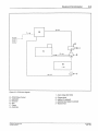
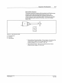
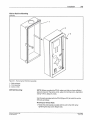
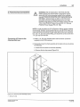
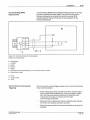
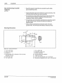
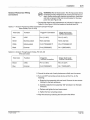
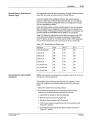
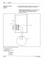
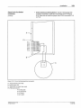
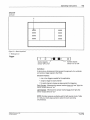
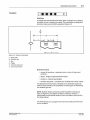
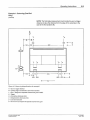
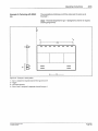
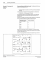
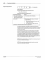
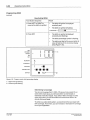
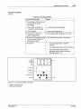
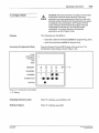
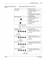
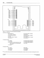
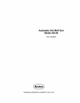
Installation
Current Sinking (NPN)
Requirements
3-15
A current sinking (NPN) device capable of sinking at least 10 rnA must
be used to stimulate the signal inputs. The internal circuitry for the
Nordson photosensor is pre-wired to include the required NPN
switching element. Figure 3.10 shows the wiring diagram for the
Nordson photosensor.
B
- 8
1
IIIII
k
A
II Ill
2
3
4
!
t"" ~
I
I
~
T
-
*
~
7
Figure 3. 10 - Nordson photosensor wiring diagram
(wired as a sinking device)
A -Photosensor
1- +12VDC
2-Signal
3-Ground
4 -Shield
5- Switching element (NPN transistor), pre-wired within sensor circuitry
6 - Pigtail wire for shield
B - PC40
7- To logic circuit
8 - +12V
Tips for Minimizing Unwanted
Triggering
The occurence of unwanted trigger signals can be reduced by following
these recommendations:
• Avoid routing sensor wires near AC power lines, solenoid output
lines, or other electrical devices (i.e., motors, contactors, relays,
etc.) that may cause electrical interference. Especially avoid
routing wires in troughs or conduits with other high
current-carrying conductors.
• Make sure that no objects other than the substrate pass between
the sensor and substrate during line operation.
• Mount the sensors within the recommended distance range of the
substrate.
C NOI'clson Corpotabon 1993
AI Aoghts Aeser.red
P/N 108 389A
57·28 1/93