1
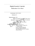
IT-230 RS-422 Interface Module v2.0 Installation Manual Warning: This manual contains information on limitations regarding product use and function and information on the limitations as to liability of the manufacturer. TABLE OF CONTENTS Note to Installers . . . . . . . . . . . . . . . . . . . . . . . . . . . . . . . . . . . . . . . . . . . . . . . . . . . . 2 General. . . . . . . . . . . . . . . . . . . . . . . . . . . . . . . . . . . . . . . . . . . . . . . . . . . . . . . . . . . . 3 Features . . . . . . . . . . . . . . . . . . . . . . . . . . . . . . . . . . . . . . . . . . . . . . . . . . . . . . . . . . . . . . . . . . 3 Ratings . . . . . . . . . . . . . . . . . . . . . . . . . . . . . . . . . . . . . . . . . . . . . . . . . . . . . . . . . . . . . . . . . . . 3 Compatibility . . . . . . . . . . . . . . . . . . . . . . . . . . . . . . . . . . . . . . . . . . . . . . . . . . . . . . . . . . . . . . . 3 IT-230 Interface Pre Installation Configuration. . . . . . . . . . . . . . . . . . . . . . . . . . . . 4 Running the RS-422 Cable . . . . . . . . . . . . . . . . . . . . . . . . . . . . . . . . . . . . . . . . . . . . . . . . . . . 4 Hardware Factory Default . . . . . . . . . . . . . . . . . . . . . . . . . . . . . . . . . . . . . . . . . . . . . . . . . . . . 4 Installing the IT-230 with Panel . . . . . . . . . . . . . . . . . . . . . . . . . . . . . . . . . . . . . . . . 4 Keybus Connection between IT-230 and Panel . . . . . . . . . . . . . . . . . . . . . . . . . . . . . . . . . . . . 5 RS-422 Connection for C24-HUB . . . . . . . . . . . . . . . . . . . . . . . . . . . . . . . . . . . . . . . . . . . . . . 5 Initial Panel Programming . . . . . . . . . . . . . . . . . . . . . . . . . . . . . . . . . . . . . . . . . . . . 6 Keypad Data Display . . . . . . . . . . . . . . . . . . . . . . . . . . . . . . . . . . . . . . . . . . . . . . . . . . . . . . . . Entering HEX values at keypad . . . . . . . . . . . . . . . . . . . . . . . . . . . . . . . . . . . . . . . . . . . . . . . . Entering ASCII Characters at keypad . . . . . . . . . . . . . . . . . . . . . . . . . . . . . . . . . . . . . . . . . . . PC1616/1832/1864 Initial Programming . . . . . . . . . . . . . . . . . . . . . . . . . . . . . . . . . . . . . . . . . 6 6 6 6 IT-230 PROGRAMMING SECTION . . . . . . . . . . . . . . . . . . . . . . . . . . . . . . . . . . . . . . 7 Programming Options . . . . . . . . . . . . . . . . . . . . . . . . . . . . . . . . . . . . . . . . . . . . . . . . . . . . . . . 7 Interactive Options . . . . . . . . . . . . . . . . . . . . . . . . . . . . . . . . . . . . . . . . . . . . . . . . . . . . . . . . . . 7 64 Zone Lifestyle Toggle Options. . . . . . . . . . . . . . . . . . . . . . . . . . . . . . . . . . . . . . . . . . . . . . . 8 64 Zone Notification Toggle Options . . . . . . . . . . . . . . . . . . . . . . . . . . . . . . . . . . . . . . . . . . . . 9 System Information (Read Only) . . . . . . . . . . . . . . . . . . . . . . . . . . . . . . . . . . . . . . . . . . . . . . 10 System Reset Defaults . . . . . . . . . . . . . . . . . . . . . . . . . . . . . . . . . . . . . . . . . . . . . . . . . . . . . . 10 PROGRAMMING WORKSHEET . . . . . . . . . . . . . . . . . . . . . . . . . . . . . . . . . . . . . . . 11 Programming Options . . . . . . . . . . . . . . . . . . . . . . . . . . . . . . . . . . . . . . . . . . . . . . . . . . . . . . Interactive Options . . . . . . . . . . . . . . . . . . . . . . . . . . . . . . . . . . . . . . . . . . . . . . . . . . . . . . . . . 64 Zone Lifestyle Toggle Options. . . . . . . . . . . . . . . . . . . . . . . . . . . . . . . . . . . . . . . . . . . . . . 64 Zone Notification Toggle Options . . . . . . . . . . . . . . . . . . . . . . . . . . . . . . . . . . . . . . . . . . . System Information (Read Only) . . . . . . . . . . . . . . . . . . . . . . . . . . . . . . . . . . . . . . . . . . . . . . System Reset Defaults . . . . . . . . . . . . . . . . . . . . . . . . . . . . . . . . . . . . . . . . . . . . . . . . . . . . . . 1 11 11 11 11 11 11 WARNING Please Read Carefully Note to Installers This Warning contains vital information. As the only individual in contact with system users, it is the installer’s responsibility to bring each item in this Warning to the attention of all users of this system. System Failures This system has been carefully designed to be as effective as possible. There are circumstances, however, involving fire, burglary, or other types of emergencies where it may not provide protection. Any alarm system of any type may be compromised deliberately or may fail to operate as expected for a variety of reasons. Some but not all of these reasons may be: Access by Intruders Intruders may enter through an unprotected access point, circumvent a sensing device, evade detection by moving through an area of insufficient coverage, disconnect a warning device, or interfere with or prevent the proper operation of the system. Component Failure Although every effort has been made to make this system as reliable as possible, the system may fail to function as intended due to the failure of a component. Compromise of Radio Frequency (Wireless) Devices Signals may not reach the receiver under all circumstances which could include metal objects placed on or near the radio path or deliberate jamming or other inadvertent radio signal interference. Criminal Knowledge This system contains security features which were known to be effective at the time of manufacture. It is possible for persons with criminal intent to develop techniques which reduce the effectiveness of these features. It is important that your security system be reviewed periodically to ensure that its features remain effective and that it is updated or replaced if it is found that it does not provide the protection expected. Failure of Replaceable Batteries This system’s wireless transmitters have been designed to provide several years of battery life under normal conditions. The expected battery life is a function of the device environment, usage, and type. Ambient conditions such as high humidity, high or low temperatures, or large temperature fluctuations may reduce the expected battery life. While each transmitting device has a low battery monitor which identifies when the batteries need to be replaced, this monitor may fail to operate as expected. Regular testing and maintenance will keep the system in good operating condition. Inadequate Installation A security system must be installed properly in order to provide adequate protection. Every installation should be evaluated by a security professional to ensure that all access points and areas are covered. Locks and latches on windows and doors must be secure and operate as intended. Windows, doors, walls, ceilings and other building materials must be of sufficient strength and construction to provide the level of protection expected. A reevaluation must be done during and after any construction activity. An evaluation by the fire and/or police department is highly recommended if this service is available. Inadequate Testing Most problems that would prevent an alarm system from operating as intended can be found by regular testing and maintenance. The complete system should be tested weekly and immediately after a break-in, an attempted break-in, a fire, a storm, an earthquake, an accident, or any kind of construction activity inside or outside the premises. The testing should include all sensing devices, keypads, consoles, alarm indicating devices, and any other operational devices that are part of the system. Insufficient Time There may be circumstances when the system will operate as intended, yet the occupants will not be protected from an emergency due to their inability to respond to the warnings in a timely manner. If the system is remotely monitored, the response may not occur in time to protect the occupants or their belongings. Motion Detectors Motion detectors can only detect motion within the designated areas as shown in their respective installation instructions. They cannot discriminate between intruders and intended occupants. Motion detectors do not provide volumetric area protection. They have multiple beams of detection and motion can only be detected in unobstructed areas covered by these beams. They cannot detect motion which occurs behind walls, ceilings, floor, closed doors, glass partitions, glass doors or windows. Any type of tampering whether intentional or unintentional such as masking, painting, or spraying of any material on the lenses, mirrors, windows or any other part of the detection system will impair its proper operation. Passive infrared motion detectors operate by sensing changes in temperature. However their effectiveness can be reduced when the ambient temperature rises near or above body temperature or if there are intentional or unintentional sources of heat in or near the detection area. Some of these heat sources could be heaters, radiators, stoves, barbeques, fireplaces, sunlight, steam vents, lighting, and so on. Power Failure Control units, intrusion detectors, smoke detectors and many other security devices require an adequate power supply for proper operation. If a device operates from batteries, it is possible for the batteries to fail. Even if the batteries have not failed, they must be charged, in good condition and installed correctly. If a device operates only by AC power, any interruption, however brief, will render that device inoperative while it does not have power. Power interruptions of any length are often accompanied by voltage fluctuations which may damage electronic equipment such as a security system. After a power interruption has occurred, immediately conduct a complete system test to ensure that the system operates as intended. Security and Insurance Regardless of its capabilities, an alarm system is not a substitute for property or life insurance. An alarm system also is not a substitute for property owners, renters, or other occupants to act prudently to prevent or minimize the harmful effects of an emergency situation. Smoke Detectors Smoke detectors that are a part of this system may not properly alert occupants of a fire for a number of reasons, some of which follow. The smoke detectors may have been improperly installed or positioned. Smoke may not be able to reach the smoke detectors, such as when the fire is in a chimney, walls or roofs, or on the other side of closed doors. Smoke detectors may not detect smoke from fires on another level of the residence or building. Every fire is different in the amount of smoke produced and the rate of burning. Smoke detectors cannot sense all types of fires equally well. Smoke detectors may not provide timely warning of fires caused by carelessness or safety hazards such as smoking in bed, violent explosions, escaping gas, improper storage of flammable materials, overloaded electrical circuits, children playing with matches or arson. Even if the smoke detector operates as intended, there may be circumstances when there is insufficient warning to allow all occupants to escape in time to avoid injury or death. Telephone Lines If telephone lines are used to transmit alarms, they may be out of service or busy for certain periods of time. Also an intruder may cut the telephone line or defeat its operation by more sophisticated means which may be difficult to detect. Warning Devices Warning devices such as sirens, bells, horns, or strobes may not warn people or waken someone sleeping if there is an intervening wall or door. If warning devices are located on a different level of the residence or premise, then it is less likely that the occupants will be alerted or awakened. Audible warning devices may be interfered with by other noise sources such as stereos, radios, televisions, air conditioners or other appliances, or passing traffic. Audible warning devices, however loud, may not be heard by a hearing-impaired person. 2 GENERAL IMPORTANT This manual shall be used in conjunction with the Alarm Controller PowerSeries Panel manual; All the safety instructions specified within that manual (or equivalent) shall be observed. The PowerSeries Panel is referenced as “panel” throughout this document. The IT-230 Interface shall be installed in the location specified in these instructions. The equipment enclosure must be fully assembled and closed, with all the necessary screws/tabs, and secured to a wall before operation. Internal wiring must be routed in a manner that prevents: • Excessive strain on wire and on terminal connections, • Interference between power limited and non power limited wiring, • Loosening of terminal; connections, or • Damage of conductor insulation. WARNING: Never install this equipment during a lightning storm! Safety Information External wiring must be protected and routed in a such a way that all the local, state, federal electrical code and regulations and fire codes are fully met; the external wiring shall pose no risks for an operator. The external wiring shall be clearly labeled at both ends. Where required, NOTIFY the local authorities in regard to the performed wiring. The Installer must instruct the System user on each of the following: • Do not attempt to service this product. Opening or removing covers may expose the user to dangerous voltages or other risks. • Any servicing shall be referred to trained service personnel only. • Use authorized accessories only with this equipment. Model Information IT-230: Is an RS-422 Interface that allows two way message transfer between DSC PC1616/PC1832/PC1864 Power Series Panel and C24-HUB. The IT-230 provides C24 Interactive monitoring and control via an RS-422 balanced line link to the C24-HUB. The link speed is 115.2 KB and is programmable by the installer. NOTE: The C24-HUB is an interface device which connects to security panels, IP cameras, sensors, Z-wave based home automation devices, etc. to deliver a host of advanced functionality. Life-style events are defined as “non alarm” events. Life-safety events are defined as “alarm” events. Features • • • • Full event reporting to central station and C24 Interactive, via RS-422 to C24-HUB. Programmable Labels. RS-422 balanced line communication to external C24-HUB up to 1,000 ft. (305 m). Buffers 1,000 date and time stamped Life Style events to C24-HUB as First In First Out (FIFO) messages. Technical Specifications The input voltage to the IT-230 Interface can be drawn from the Underwriters Laboratories/Underwriters Laboratories Canada (UL/ULC) Listed Control Panel or provided by an external UL/ULC Listed power supply rated for the application (external power-limited source). NOTE: The power supply must be Class II, Power Limited. Ratings Table 1: IT-230 Interface Module Ratings IT-230 Interface Module Model POWER SUPPLY RATINGS Input Voltage 11.1~12.6 VDC CURRENT CONSUMPTION Standby Current 140mA @ 12 VDC ENVIRONMENTAL SPECIFICATIONS Operating Temperature Humidity 0°C - 49°C (32°F- 120°F) 5% ~ 93% relative humidity, non-condensing MECHANICAL SPECIFICATIONS Board Dimensions (mm) Weight (grams) 150 × 50 × 15 45 Compatibility Interface IT-230 Panel Power Series Table 2: Compatible Power Panels Description • Power Series PC1616, version 4.5+ • Power Series PC1832, version 4.5+ • Power Series PC1864, version 4.5+ NOTE: Enter [*][8][Installer Code] [900] at keypad to view the Power Panel Version number. 3 IT-230 INTERFACE PRE INSTALLATION CONFIGURATION This IT-230 Interface is fixed and shall be installed in the Panel by Service Persons only. (Service Person is defined as a person having appropriate technical training and experience necessary to be aware of hazards to which that person may be exposed in performing a task and of measures to minimize the risks to that person or other persons). The IT-230 shall be installed and used within an environment that provides the pollution degree max 2, over voltages category II, in non-hazardous, indoor locations only. This manual shall be used with the Installation Manual of the panel which is connected to the IT-230. All instructions specified within the panel manual and the C24-HUB manual must be observed. All the local rules imposed by local electrical codes shall be observed and respected during installation. Running the RS-422 Cable An RS-422 cable must be connected to the C24-HUB and cable run to the IT-230 module inside the panel. NOTE: Maximum cable length for RS-422 cable is 305 m (1,000 ft.) At the C24-HUB, attach wires for RS-422 connection as follows: 1. Securely fasten the TX+ wire on the terminal block. 2. Securely fasten the TX- wire on the terminal block. 3. Connect a 120 , ¼ W resistor between RX+ and RX- terminals on the C24-HUB. 4. Securely fasten the RX+ wire on the terminal block. 5. Securely fasten the RX- wire on the terminal block. 6. Securely fasten the GND wire on the terminal block. (Optional, DSC recommends connection.) Table 3: RS-422 Connector Pin Assignment PIN Signal Name 1 2 3 4 5 TX + TX - RX + RX - GND 7. Run the RS-422 Cable from the C24-HUB to the IT-230 mounted inside the Panel. Hardware Factory Default The IT-230 can be hardware reset to Factory Default by removing AC power, Battery + terminal, and telephone line, then installing a jumper between the BLK and DEF pins on the IT-230 Keybus connector (left terminal block) and restarting the IT-230. (See Figure 2.) NOTE: Installing the Default (DEF) jumper during normal operation has no effect. INSTALLING THE IT-230 WITH PANEL Installing IT-230 with PC1616/1832/1864 Panel WARNING! BEFORE INSTALLING THE IT-230 BOARD WITHIN THE ALARM CONTROLLER ENCLOSURE, DISCONNECT ALL POWER AND TELEPHONE LINES FROM THE PANEL. DG009590 Figure 1 IT-230 Panel Mounting (c) Insert (5) plastic standoffs (d) Mount IT-230 on standoffs 1. To mount the IT-230 in the panel, perform the following: a. Remove the Panel front cover. b. Remove the 5 white plastic standoffs from the bag provided with the IT-230 kit. c. Insert the 5 standoffs into the holes on the left side of the Panel as shown in Figure 1 (left view). d. Orient the IT-230 with the standoffs on left side of Panel and push the IT-230 firmly and evenly onto the standoffs until it is securely attached to the Panel. e. Remove the PC-LINK cable from the supplied IT-230 kit and attach one end of the PC-LINK cable to the PC1616/1832/1864 PC-LINK header. (Red wire on Pin 1 of the Panel). f. Attach the other end of the PC-LINK cable to the IT-230 PC-LINK connector. (Black wire on Pin 1). 4 WARNING! THE IT-230 INTERFACE OUTPUT CIRCUITS ARE POWER LIMITED. DO NOT ROUTE ANY WIRING OVER THE CIRCUIT BOARD. MAINTAIN AT LEAST 25.4MM (1IN.) SEPARATION BETWEEN CIRCUIT BOARD AND WIRING. A MINIMUM OF 7MM (1/4 IN.) SEPARATION MUST BE MAINTAINED AT ALL POINTS BETWEEN NON-POWER LIMITED WIRING AND POWER LIMITED WIRING. Keybus Connection between IT-230 and Panel 2. Wire the Keybus connections between Panel and the IT-230 TB3 as follows: See Figure 2. a. Attach a wire from the IT-230 RED terminal to the panel’s RED terminal. b. Attach a wire from the IT-230 BLK terminal to the panel’s BLK terminal. c. Attach a wire from the IT-230 YEL terminal to the panel’s YEL terminal. d. Attach a wire from the IT-230 GRN terminal to the panel’s GRN terminal. NOTE: Do not attach any wires to the “DEF” terminal on the IT-230. RS-422 Connection for C24-HUB 3. Terminate the previously run RS-422 cable from the C24-HUB to the IT-230 TB2 as follows: See Figure 2. a. Connect the TX+ wire to the RX+ terminal on the IT-230. b. Connect the TX- wire to the RX- terminal on the IT-230. c. Connect the RX+ wire to the TX+ terminal on the IT-230. d. Connect the RX- wire to the TX- terminal on the IT-230. e. Connect the ground wire to the GND terminal on the IT-230.(Optional - DSC recommends connection). 4. Perform the following steps for initial power on of the panel with IT-230 installed: a. Reconnect the AC power, Battery + connector, and Telephone line to the Panel. (The IT-230 and Panel will power up together). b. Observe that the IT-230’s Network and Trouble LEDs are flashing together while the interface initializes. Both LEDs will continue to flash until the IT-230 has successfully initialized and is ready for operation. Figure 2 IT-230 Wiring Diagram IT-230 Interface Module (UA588) Trouble Network LED LED RED Wire to Gateway RS-422 cable to Gateway Max. Length 305m 1,000 feet Wire IT-230 to Panel RED 1 2 3 4 PC-LINK Header DG009734 PC1616/PC1832/PC1864 TB-2 5 Gateway INTERFACE STATUS LEDS The Interface has 2 yellow LED indicators: 1 Trouble LED, 1 Network connection status LED, The LED meanings are described in this Section. Yellow Trouble LED This yellow LED will flash to indicate a trouble on the unit. The number of flashes indicates the type of trouble. See the table below for the coded flashes and the conditions which will activate the Trouble Status LED. Table 4: Yellow Trouble Status LED Number of Flashes Trouble 2 Panel Supervision Trouble 10 Configuration Failure 12 Module Configuration Trouble NOTE: Only the highest priority trouble (2 Flashes is highest priority) is indicated. When that trouble is restored, the next highest trouble will indicate, if present. This will continue until all Troubles have been cleared (Trouble LED is OFF). The following paragraphs describe the conditions associated with the trouble indicated: 2 Flashes: Panel Supervision Trouble This trouble will be indicated when communication between the IT-230 module and the Panel fails. If the module can not communicate with the panel (e.g., loss of power to the panel) the IT-230 will send a Panel Absent Trouble (Section [023]) event message to the Change to C24-HUB. When communication is restored, the IT-230 will send a Panel Absent Restore (Section [024]) event message to the C24-HUB. The reporting codes are ET0001 (Trouble) and ER0001 (Trouble Restore). The Panel Absent/Restore events always use primary receiver Account Code (See Section [021]) when communicating these events. NOTE: The Panel Absent Trouble/Restore are internally generated events by the IT-230. These are the only internal events created; all other events are generated by the Panel. The Trouble is generated if the IT-230 misses 6 consecutive polls to the panel and is restored on successful receipt of a single poll. 10 Flashes: Configuration Failure This trouble is indicated when the unit fails to receive remote programming. 12 Flashes: Module Configuration Failure This trouble is indicated when the System Account Code has not been programmed in Section [021]. Yellow Connection Status LED BLINKING: Indicates communication is in progress between IT-230 and the C24-HUB. • Once quickly for outgoing transmission from the IT-230. • Twice quickly to indicate incoming ACK/NACK from the C24-HUB. OFF: This is the normal state of the Connection Status LED. There are no connection issues present. ON: There is a problem with the connection. The yellow LED will be ON when trouble is indicated: INITIAL PANEL PROGRAMMING Keypad Data Display • Section-Toggle Options: The number is displayed when Toggle is ON, the number is not displayed when Toggle is OFF. (e.g., Toggle Options displays: [--3--6--]. Options 3 and 6 are ON, all others are OFF). Pressing keys 1 through 8 will alternately turn the Toggle ON and OFF. • HEX/Decimal Data: Values that are provided with two defaults, separated by a slash (/) character, use the format: hexadecimal followed by decimal equivalent (e.g., Default [0BF5/3061]). Hexadecimal numbers are shown, with all leading zeroes, to the full field length defined for the number. Entering HEX values at keypad To enter HEX values at the keypad, you must press the * key before entering the HEX value. (e.g., to enter HEX value C at the keypad, press [*] [3]. Entering ASCII Characters at keypad 1. 2. 3. 4. Press [*] and use the scroll buttons [<] [>] to display ASCII Entry on the keypad screen. Press [*] to select ASCII entry mode. Use the [<] [>] scroll keys to display the character you want and press [*] to save and exit ASCII entry. Repeat the steps above to enter another ASCII character. PC1616/1832/1864 Initial Programming Perform the following steps to ensure that the IT-230 and the panel work together as intended. These Sections must be programmed at the panel keypad. Enter [*][8][Installer Code][Section Number]. Record any values that are modified from their default, in the appropriate Programming Worksheets for the Panel. 1. In Panel Section [167] program 060 (seconds). 2. In Panel Section [382] set Option [5] ON. 3. In Panel Section [383] set Option [7] ON. (Interactive bidirectional, events and logs, firmware upgrade). 4. In Panel Section [383] set Option [8] ON for CID, or OFF for SIA. 6 IT-230 PROGRAMMING SECTION The Programming Sections in this document are accessed via panel Section for Ethernet/GPRS Programming. Enter: [*][8][installer code][851][# # # ], Where # # # is the 3 digit Section number referenced in this Programming section. The worksheet at the end of this document can be used to record new values when programming changes have been made from their default values. Default values are provided for each Section. NOTE: Programmed values can not be modified using the keypad. Installers may review/record programming Option values at the keypad. Programming Options [011] Installer Code Default (CAFE) Program your installer code for this IT-230 module. The installer code is required whenever programming of the IT-230 module is required. Valid range: 0000 - FFFF. [021] Account Code Default (FFFFFF) The Account Code is included when transmitting events generated by the IT-230. (e.g., Panel Absent Trouble). It is recommended that the IT-230 Account Code be the same as the Panel Account Number. Valid range: 000001FFFFFE. If 4 digit account codes are needed the 2 lowest digits shall be programmed as FF;(e.g., Account Code 1234 is programmed as:1234FF). Programming this Section as all 0 or all F will cause a Module Configuration Trouble (Trouble LED = 12 flashes). NOTE: 12 flashes are indicated on the IT-230 only. This status is NOT communicated to the panel. [022] Communications Format Default (04) The module can be configured to send IT-230 Events in SIA or CID format. Program 03 for CID. Program 04 for SIA. The SIA communication format follows the level 2 specifications of the SIA Digital Communication Standard October 1997. This format will send the Account Code programmed in Section [021] along with its data transmission. The transmission will look similar to the following at the receiver: Nri0 ET001 Where: N = New Event; ri0 = Partition/Area identifier; ET = [023] Panel Absent Trouble; 001 = Zone 001. IT-230 Communications Reporting Codes Table 5: Communications Reporting Codes Event [023] Panel Absent Trouble [024] Panel Absent Trouble Restore SIA SIA Identifier Reporting Code ET 001 ER 001 CID Qualifier 1 3 CID Event Code 3 3 CID Reporting Code 55 55 CID User/ Zone 001 001 [023] Panel Absent Trouble Default (FF) Program 00 to disable this event or FF to enable. This event will occur when communications with the panel have been lost for more than 60 seconds. [024] Panel Absent Trouble Restore Default (FF) Program 00 to disable this event or FF to enable. This event will occur when communications with the control panel have resumed. Interactive Options [651] Interactive Account Code Default (000000) This section is programmed with the interactive Account Code of the IT-230. [661] Interactive Baud Rate Default (05) This section is programmed with the baud rate used. Valid entries are provided in the table below. Default baud rate is 115.2 KB. HEX Value Baud Rate 01 9600 Table 6: Interactive Baud Rate Settings 03 04 05 38400 57600 115200 02 19200 7 [662] Interactive Port Settings Toggle Program this section Toggles to select the Parity used for Interactive data transfers: [1] Parity Enable Default (OFF) ON: Parity enabled. OFF: Parity disabled. [2] Parity Type Default (OFF) ON: Even Parity enabled. OFF: Odd Parity enabled. [3] Stop Bits Default (OFF) ON: 1 Stop bit is used. OFF: 2 Stop bits are used. [4] Flow Control Default (OFF) ON: Flow Control enabled. OFF: Flow Control disabled. [5]-[8]Reserved Default (OFF) [671] Lifestyle Event Toggle This section determines the events recorded in the Lifestyle Log. When the lifestyle log buffer is 75% full, the IT-230 will connect to the server and upload the lifestyle information. The log can buffer 1,000, variable length, lifestyle events. NOTE: No Failure To Communicate (FTC) error shall be generated for Lifestyle Events. [1] Lifestyle Log Alarm/Restore Default (ON) [2] Lifestyle Log Tamper/Restore Default (ON) [3] Lifestyle Log Opening/Closing Default (ON) [4] Lifestyle Log System Maintenance Default (ON) [5] Lifestyle Log System Test Default (ON) [6] Lifestyle Log IT-230 Events Default (ON) [7]-[8] Reserved Default (ON) 64 Zone Lifestyle Toggle Options [672] Lifestyle Zone 1 - 8 Toggle Options The default for each Lifestyle Zone Toggle is ON. Table 7: Lifestyle Zone 1 - 8 Toggle TOGGLE ZONE 01 1 02 2 03 3 04 4 05 5 06 6 07 7 08 8 [673] Lifestyle Zone 9 - 16 Toggle Options The default for each Lifestyle Zone Toggle is ON. Table 8: Lifestyle Zone 9 - 16 Toggle TOGGLE ZONE 01 9 02 10 03 11 04 12 05 13 06 14 07 15 08 16 [674] Lifestyle Zone 17 - 24 Toggle Options The default for each Lifestyle Zone Toggle is ON. Table 9: Lifestyle Zone 17 - 24 Toggle TOGGLE ZONE 01 17 02 18 03 19 04 20 8 05 21 06 22 07 23 08 24 [675] Lifestyle Zone 25 - 32 Toggle Options The default for each Lifestyle Zone Toggle is ON. Table 10: Lifestyle Zone 25 - 32 Toggle TOGGLE ZONE 01 25 02 26 03 27 04 28 05 29 06 30 07 31 08 32 [676] Lifestyle Zone 33 - 40 Toggle Options The default for each Lifestyle Zone Toggle is ON. Table 11: Lifestyle Zone 33 - 40 Toggle TOGGLE ZONE 01 33 02 34 03 35 04 36 05 37 06 38 07 39 08 40 [677] Lifestyle Zone 41 - 48 Toggle Options The default for each Lifestyle Zone Toggle is ON. Table 12: Lifestyle Zone 41 - 48 Toggle TOGGLE ZONE 01 41 02 42 03 43 04 44 05 45 06 46 07 47 08 48 [678] Lifestyle Zone 49 - 56 Toggle Options The default for each Lifestyle Zone Toggle is ON. Table 13: Lifestyle Zone 49 - 56 Toggle TOGGLE ZONE 01 49 02 50 03 51 04 52 05 53 06 54 07 55 08 56 [679] Lifestyle Zone 57 - 64 Toggle Options The default for each Lifestyle Zone Toggle is ON. Table 14: Lifestyle Zone 57 - 64 Toggle TOGGLE ZONE 01 57 02 58 03 59 04 60 05 61 06 62 07 63 08 64 [681] Notification Event Toggle This section determines the Notification events that are reported. Default for all Toggles is ON. [1] Lifestyle Log Alarm/Restore Default (ON) [2] Lifestyle Log Tamper/Restore Default (ON) [3] Lifestyle Log Opening/Closing Default (ON) [4] Lifestyle Log System Maintenance Default (ON) [5] Lifestyle Log System Test Default (ON) [6] Lifestyle Log IT-230 Events Default (ON) [7]-[8] Reserved Default (ON) 64 Zone Notification Toggle Options [682] Notification Zone 1 - 8 Toggle Options The default for each Notification Zone Toggle is ON. Table 15: Notification Zone 1 - 8 Toggle TOGGLE ZONE 01 1 02 2 03 3 04 4 05 5 06 6 07 7 08 8 [683] Notification Zone 9 - 16 Toggle Options The default for each Notification Zone Toggle is ON. Table 16: Notification Zone 9 - 16 Toggle TOGGLE ZONE 01 9 02 10 03 11 04 12 05 13 06 14 07 15 08 16 [684] Notification Zone 17 - 24 Toggle Options The default for each Notification Zone Toggle is ON. Table 17: Notification Zone 17 - 24 Toggle TOGGLE ZONE 01 17 02 18 03 19 04 20 9 05 21 06 22 07 23 08 24 [685] Notification Zone 25 - 32 Toggle Options The default for each Notification Zone Toggle is ON. Table 18: Notification Zone 25 - 32 Toggle TOGGLE ZONE 01 25 02 26 03 27 04 28 05 29 06 30 07 31 08 32 [686] Notification Zone 33 - 40 Toggle Options The default for each Notification Zone Toggle is ON. Table 19: Notification Zone 33 - 40 Toggle TOGGLE ZONE 01 33 02 34 03 35 04 36 05 37 06 38 07 39 08 40 [687] Notification Zone 41 - 48 Toggle Options The default for each Notification Zone Toggle is ON. Table 20: Notification Zone 41 - 48 Toggle TOGGLE ZONE 01 41 02 42 03 43 04 44 05 45 06 46 07 47 08 48 [688] Notification Zone 49 - 56 Toggle Options The default for each Notification Zone Toggle is ON. Table 21: Notification Zone 49 - 56 Toggle TOGGLE ZONE 01 49 02 50 03 51 04 52 05 53 06 54 07 55 08 56 [689] Notification Zone 57 - 64 Toggle Options The default for each Notification Zone Toggle is ON. Table 22: Notification Zone 57 - 64 Toggle TOGGLE ZONE 01 57 02 58 03 59 04 60 05 61 06 62 07 63 08 64 System Information (Read Only) NOTE: Sections [987] - [991] are provided for information (Read Only). Values in these Sections cannot be modified. [987] Language Version This Section will display the current Language version of the IT-230. [990] Boot Loader Version This Section will display the current Boot Loader version of the IT-230. [991] Firmware Version This Section will display the current firmware version of the device. Update worksheets with new version after a flash update is completed. System Reset Defaults [999] Software Default Default (99) Software default allows the installer to refresh the unit after changes and also return the IT-230 to default state. 00: Default Module. All programming Sections in module reset to factory settings. NOTE: This will erase all existing programming of the IT-230. 55: Reset. The IT-230 is reset. This option is equivalent to power cycling the IT-230. 10 PROGRAMMING WORKSHEET Programming Options [677] Lifestyle Zone 41 - 48 Toggle Options |____|____|____|____|____|____|____|____| [011] Installer Code 41 42 43 44 45 46 47 48 Default (CAFE) Valid range: 0000 - FFFF. |____|____|____|____| [678] Lifestyle Zone 49 - 56 Toggle Options [021] Account Code |____|____|____|____|____|____|____|____| Default (FFFFFF) Valid range: 000001 - FFFFFE. |____|____|____|____|____|____| 49 50 51 52 53 54 55 56 [679] Lifestyle Zone 57 - 64 Toggle Options [022] Communications Format |____|____|____|____|____|____|____|____| Default (04) Program 03 (CID), 04 (SIA). |____|____| 57 58 59 60 61 62 63 64 [681] Notification Event Toggle [023] Panel Absent Trouble |____| [1] Alarm/Restore Default (ON). |____| [2] Tamper/Restore Default (ON). |____| [3] Opening/Closing Default (ON). |____| [4] System Maintenance. Default (ON). |____| [5] System Test Default (ON). |____| [6] Internal Events Default (ON). Default (FF) |____|____| [024] Panel Absent Trouble Restore Default (FF) Program 00 disable or FF enable. |____|____| Interactive Options [651] Interactive Account Code 64 Zone Notification Toggle Options Default (000000) |____|____|____|____|____|____| [682] Notification Zone 1 - 8 Toggle Options |____|____|____|____|____|____|____|____| 1 [661] Interactive Baud Rate Default (05) 2 3 4 5 6 7 8 [683] Notification Zone 9 - 16 Toggle Options |____|____| |____|____|____|____|____|____|____|____| [662] Interactive Port Settings Toggle 9 |____| [1] Parity Enabled Default (OFF). |____| [2] Even/Odd Parity Default (OFF). |____| [3]1 or 2 Stop Bits Default (OFF). |____| [4] Flow Control. Default (OFF). 10 11 12 13 14 15 16 [684] Notification Zone 17 - 24 Toggle Options |____|____|____|____|____|____|____|____| 17 18 19 20 21 22 23 24 [685] Notification Zone 25 - 32 Toggle Options [671] Lifestyle Event Toggle |____|____|____|____|____|____|____|____| |____| [1] Alarm/Restore Default (ON). |____| [2] Tamper/Restore Default (ON). |____| [3] Opening/Closing Default (ON). |____| [4] System Maintenance Default (ON). |____| [5] System Test Default (ON). |____| [6] Internal Events Default (ON). 25 26 27 28 29 30 31 32 [686] Notification Zone 33 - 40 Toggle Options |____|____|____|____|____|____|____|____| 33 34 35 36 37 38 39 40 [687] Notification Zone 41 - 48 Toggle Options 64 Zone Lifestyle Toggle Options |____|____|____|____|____|____|____|____| [672] Lifestyle Zone 1 - 8 Toggle Options 41 42 43 44 45 46 47 48 |____|____|____|____|____|____|____|____| 1 2 3 4 5 6 7 [688] Notification Zone 49 - 56 Toggle Options 8 |____|____|____|____|____|____|____|____| [673] Lifestyle Zone 9 - 16 Toggle Options 49 50 51 52 53 54 55 56 |____|____|____|____|____|____|____|____| 9 10 [689] Notification Zone 57 - 64 Toggle Options 11 12 13 14 15 16 |____|____|____|____|____|____|____|____| [674] Lifestyle Zone 17 - 24 Toggle Options 57 58 59 60 61 62 63 64 |____|____|____|____|____|____|____|____| System Information (Read Only) 17 18 19 20 21 22 23 24 [991] Firmware Version [675] Lifestyle Zone 25 - 32 Toggle Options |____|____|____|____|____|____|____|____| |____|____|____|____|____|____|____|____| 25 26 27 28 29 System Reset Defaults 30 31 32 [999] Software Default [676] Lifestyle Zone 33 - 40 Toggle Options Default (99) |____|____| |____|____|____|____|____|____|____|____| 33 34 35 36 37 38 39 40 11 END USER LICENCE AGREEMENT IMPORTANT - READ CAREFULLY: DSC Software purchased with or without Products and Components is copyrighted and is purchased under the following license terms: This End-User License Agreement (“EULA”) is a legal agreement between You (the company, individual or entity who acquired the Software and any related Hardware) and Digital Security Controls, a division of Tyco Safety Products Canada Ltd. (“DSC”), the manufacturer of the integrated security systems and the developer of the software and any related products or components (“HARDWARE”) which You acquired. and conditions of this EULA. In such event, You must destroy all copies of the SOFTWARE PRODUCT and all of its component parts. (g)Trademarks - This EULA does not grant You any rights in connection with any trademarks or service marks of DSC or its suppliers. 3. COPYRIGHT - All title and intellectual property rights in and to the SOFTWARE PRODUCT (including but not limited to any images, photographs, and text incorporated into the SOFTWARE PRODUCT), the accompanying printed materials, and any copies of the SOFTWARE PRODUCT, are owned by DSC or its suppliers. You may not copy the printed materials accompanying the SOFTWARE PRODUCT. All title and intellectual property rights in and to the content which may be accessed through use of the SOFTWARE PRODUCT are the property of the respective content owner and may be protected by applicable copyright or other intellectual property laws and treaties. This EULA grants You no rights to use such content. All rights not expressly granted under this EULA are reserved by DSC and its suppliers. 4. EXPORT RESTRICTIONS - You agree that You will not export or re-export the SOFTWARE PRODUCT to any country, person, or entity subject to Canadian export restrictions. 5. CHOICE OF LAW - This Software License Agreement is governed by the laws of the Province of Ontario, Canada. 6. ARBITRATION - All disputes arising in connection with this Agreement shall be determined by final and binding arbitration in accordance with the Arbitration Act, and the parties agree to be bound by the arbitrator’s decision. The place of arbitration shall be Toronto, Canada, and the language of the arbitration shall be English. 7. LIMITED WARRANTY (a) NO WARRANTY - DSC PROVIDES THE SOFTWARE “AS IS” WITHOUT WARRANTY. DSC DOES NOT WARRANT THAT THE SOFTWARE WILL MEET YOUR REQUIREMENTS OR THAT OPERATION OF THE SOFTWARE WILL BE UNINTERRUPTED OR ERROR-FREE. (b) CHANGES IN OPERATING ENVIRONMENT - DSC shall not be responsible for problems caused by changes in the operating characteristics of the HARDWARE, or for problems in the interaction of the SOFTWARE PRODUCT with nonDSC-SOFTWARE or HARDWARE PRODUCTS. (c) LIMITATION OF LIABILITY; WARRANTY REFLECTS ALLOCATION OF RISK - IN ANY EVENT, IF ANY STATUTE IMPLIES WARRANTIES OR CONDITIONS NOT STATED IN THIS LICENSE AGREEMENT, DSC’S ENTIRE LIABILITY UNDER ANY PROVISION OF THIS LICENSE AGREEMENT SHALL BE LIMITED TO THE GREATER OF THE AMOUNT ACTUALLY PAID BY YOU TO LICENSE THE SOFTWARE PRODUCT AND FIVE CANADIAN DOLLARS (CAD$5.00). BECAUSE SOME JURISDICTIONS DO NOT ALLOW THE EXCLUSION OR LIMITATION OF LIABILITY FOR CONSEQUENTIAL OR INCIDENTAL DAMAGES, THE ABOVE LIMITATION MAY NOT APPLY TO YOU. (d) DISCLAIMER OF WARRANTIES - THIS WARRANTY CONTAINS THE ENTIRE WARRANTY AND SHALL BE IN LIEU OF ANY AND ALL OTHER WARRANTIES, WHETHER EXPRESSED OR IMPLIED (INCLUDING ALL IMPLIED WARRANTIES OF MERCHANTABILITY OR FITNESS FOR A PARTICULAR PURPOSE) AND OF ALL OTHER OBLIGATIONS OR LIABILITIES ON THE PART OF DSC. DSC MAKES NO OTHER WARRANTIES. DSC NEITHER ASSUMES NOR AUTHORIZES ANY OTHER PERSON PURPORTING TO ACT ON ITS BEHALF TO MODIFY OR TO CHANGE THIS WARRANTY, NOR TO ASSUME FOR IT ANY OTHER WARRANTY OR LIABILITY CONCERNING THIS SOFTWARE PRODUCT. (e) EXCLUSIVE REMEDY AND LIMITATION OF WARRANTY - UNDER NO CIRCUMSTANCES SHALL DSC BE LIABLE FOR ANY SPECIAL, INCIDENTAL, CONSEQUENTIAL OR INDIRECT DAMAGES BASED UPON BREACH OF WARRANTY, BREACH OF CONTRACT, NEGLIGENCE, STRICT LIABILITY, OR ANY OTHER LEGAL THEORY. SUCH DAMAGES INCLUDE, BUT ARE NOT LIMITED TO, LOSS OF PROFITS, LOSS OF THE SOFTWARE PRODUCT OR ANY ASSOCIATED EQUIPMENT, COST OF CAPITAL, COST OF SUBSTITUTE OR REPLACEMENT EQUIPMENT, FACILITIES OR SERVICES, DOWN TIME, PURCHASERS TIME, THE CLAIMS OF THIRD PARTIES, INCLUDING CUSTOMERS, AND INJURY TO PROPERTY. WARNING: DSC recommends that the entire system be completely tested on a regular basis. However, despite frequent testing, and due to, but not limited to, criminal tampering or electrical disruption, it is possible for this SOFTWARE PRODUCT to fail to perform as expected. If the DSC software product (“SOFTWARE PRODUCT” or “SOFTWARE”) is intended to be accompanied by HARDWARE, and is NOT accompanied by new HARDWARE, You may not use, copy or install the SOFTWARE PRODUCT. The SOFTWARE PRODUCT includes computer software, and may include associated media, printed materials, and “online” or electronic documentation. Any software provided along with the SOFTWARE PRODUCT that is associated with a separate end-user license agreement is licensed to You under the terms of that license agreement. By installing, copying, downloading, storing, accessing or otherwise using the SOFTWARE PRODUCT, You agree unconditionally to be bound by the terms of this EULA, even if this EULA is deemed to be a modification of any previous arrangement or contract. If You do not agree to the terms of this EULA, DSC is unwilling to license the SOFTWARE PRODUCT to You, and You have no right to use it. SOFTWARE PRODUCT LICENSE The SOFTWARE PRODUCT is protected by copyright laws and international copyright treaties, as well as other intellectual property laws and treaties. The SOFTWARE PRODUCT is licensed, not sold. 1.GRANT OF LICENSE This EULA grants You the following rights: (a)Software Installation and Use - For each license You acquire, You may have only one copy of the SOFTWARE PRODUCT installed. (b)Storage/Network Use - The SOFTWARE PRODUCT may not be installed, accessed, displayed, run, shared or used concurrently on or from different computers, including a workstation, terminal or other digital electronic device (“Device”). In other words, if You have several workstations, You will have to acquire a license for each workstation where the SOFTWARE will be used. (c)Backup Copy - You may make back-up copies of the SOFTWARE PRODUCT, but You may only have one copy per license installed at any given time. You may use the back-up copy solely for archival purposes. Except as expressly provided in this EULA, You may not otherwise make copies of the SOFTWARE PRODUCT, including the printed materials accompanying the SOFTWARE. 2. DESCRIPTION OF OTHER RIGHTS AND LIMITATIONS (a)Limitations on Reverse Engineering, Decompilation and Disassembly - You may not reverse engineer, decompile, or disassemble the SOFTWARE PRODUCT, except and only to the extent that such activity is expressly permitted by applicable law notwithstanding this limitation. You may not make any changes or modifications to the Software, without the written permission of an officer of DSC. You may not remove any proprietary notices, marks or labels from the Software Product. You shall institute reasonable measures to ensure compliance with the terms and conditions of this EULA. (b)Separation of Components - The SOFTWARE PRODUCT is licensed as a single product. Its component parts may not be separated for use on more than one HARDWARE unit. (c)Single INTEGRATED PRODUCT - If You acquired this SOFTWARE with HARDWARE, then the SOFTWARE PRODUCT is licensed with the HARDWARE as a single integrated product. In this case, the SOFTWARE PRODUCT may only be used with the HARDWARE as set forth in this EULA. (d)Rental - You may not rent, lease or lend the SOFTWARE PRODUCT. You may not make it available to others or post it on a server or web site. (e)Software Product Transfer - You may transfer all of Your rights under this EULA only as part of a permanent sale or transfer of the HARDWARE, provided You retain no copies, You transfer all of the SOFTWARE PRODUCT (including all component parts, the media and printed materials, any upgrades and this EULA), and provided the recipient agrees to the terms of this EULA. If the SOFTWARE PRODUCT is an upgrade, any transfer must also include all prior versions of the SOFTWARE PRODUCT. (f)Termination - Without prejudice to any other rights, DSC may terminate this EULA if You fail to comply with the terms 12 Limited Warranty Digital Security Controls warrants the original purered by this warranty, or otherwise out of warranty chaser that for a period of twelve months from the due to age, misuse, or damage shall be evaluated, date of purchase, the product shall be free of defects and a repair estimate shall be provided. No repair in materials and workmanship under normal use. Durwork will be performed until a valid purchase order is ing the warranty period, Digital Security Controls received from the Customer and a Return Merchanshall, at its option, repair or replace any defective dise Authorization number (RMA) is issued by DSC's product upon return of the product to its factory, at no Customer Service. charge for labour and materials. Any replacement Digital Security Controls’ liability for failure to repair and/or repaired parts are warranted for the remainder the product under this warranty after a reasonable of the original warranty or ninety (90) days, whichever number of attempts will be limited to a replacement of is longer. The original purchaser must promptly notify the product, as the exclusive remedy for breach of Digital Security Controls in writing that there is defect warranty. Under no circumstances shall Digital Secuin material or workmanship, such written notice to be rity Controls be liable for any special, incidental, or received in all events prior to expiration of the warconsequential damages based upon breach of warranty period. There is absolutely no warranty on softranty, breach of contract, negligence, strict liability, or ware and all software products are sold as a user any other legal theory. Such damages include, but license under the terms of the software license agreeare not limited to, loss of profits, loss of the product or ment included with the product. The Customer any associated equipment, cost of capital, cost of assumes all responsibility for the proper selection, substitute or replacement equipment, facilities or serinstallation, operation and maintenance of any prodvices, down time, purchaser’s time, the claims of third ucts purchased from DSC. Custom products are only parties, including customers, and injury to property. warranted to the extent that they do not function upon The laws of some jurisdictions limit or do not allow the delivery. In such cases, DSC can replace or credit at disclaimer of consequential damages. If the laws of its option. such a jurisdiction apply to any claim by or against International Warranty DSC, the limitations and disclaimers contained here shall be to the greatest extent permitted by law. The warranty for international customers is the same Some states do not allow the exclusion or limitation of as for any customer within Canada and the United incidental or consequential damages, so that the States, with the exception that Digital Security Conabove may not apply to you. trols shall not be responsible for any customs fees, taxes, or VAT that may be due. Disclaimer of Warranties Warranty Procedure This warranty contains the entire warranty and shall be in lieu of any and all other warranties, whether To obtain service under this warranty, please return expressed or implied (including all implied warranties the item(s) in question to the point of purchase. All of merchantability or fitness for a particular purpose) authorized distributors and dealers have a warranty And of all other obligations or liabilities on the part of program. Anyone returning goods to Digital Security Digital Security Controls. Digital Security Controls Controls must first obtain an authorization number. neither assumes responsibility for, nor authorizes any Digital Security Controls will not accept any shipment other person purporting to act on its behalf to modify whatsoever for which prior authorization has not been or to change this warranty, nor to assume for it any obtained. other warranty or liability concerning this product. Conditions to Void Warranty This disclaimer of warranties and limited warranty are This warranty applies only to defects in parts and governed by the laws of the province of Ontario, Canworkmanship relating to normal use. It does not ada. cover: WARNING: Digital Security Controls recommends •damage incurred in shipping or handling; that the entire system be completely tested on a regu•damage caused by disaster such as fire, flood, wind, lar basis. However, despite frequent testing, and due earthquake or lightning; to, but not limited to, criminal tampering or electrical •damage due to causes beyond the control of Digital disruption, it is possible for this product to fail to perSecurity Controls such as excessive voltage, form as expected. mechanical shock or water damage; Installer’s Lockout •damage caused by unauthorized attachment, alteraAny products returned to DSC which have the tions, modifications or foreign objects; Installer’s Lockout option enabled and exhibit no •damage caused by peripherals (unless such periphother problems will be subject to a service charge. erals were supplied by Digital Security Controls); Out of Warranty Repairs •defects caused by failure to provide a suitable instalDigital Security Controls will at its option repair or lation environment for the products; replace out-of-warranty products which are returned •damage caused by use of the products for purposes to its factory according to the following conditions. other than those for which it was designed; Anyone returning goods to Digital Security Controls •damage from improper maintenance; must first obtain an authorization number. Digital •damage arising out of any other abuse, mishandling Security Controls will not accept any shipment whator improper application of the products. soever for which prior authorization has not been obtained. Items Not Covered by Warranty Products which Digital Security Controls determines In addition to the items which void the Warranty, the to be repairable will be repaired and returned. A set following items shall not be covered by Warranty: (i) fee which Digital Security Controls has predeterfreight cost to the repair centre; (ii) products which mined and which may be revised from time to time, are not identified with DSC's product label and lot will be charged for each unit repaired. number or serial number; (iii) products disassembled or repaired in such a manner as to adversely affect Products which Digital Security Controls determines performance or prevent adequate inspection or testnot to be repairable will be replaced by the nearest ing to verify any warranty claim. Access cards or tags equivalent product available at that time. The current returned for replacement under warranty will be credmarket price of the replacement product will be ited or replaced at DSC's option. Products not covcharged for each replacement unit. 13 14 FCC Compliance Statement CAUTION: Changes or modifications not expressly approved by the manufacturer could void your authority to use this equipment. This equipment has been tested and found to comply with the limits for a Class B digital device, pursuant to Part 15 of the FCC Rules. These limits are designed to provide reasonable protection against harmful interference in a residential installation. This equipment generates, uses and can radiate radio frequency energy and, if not installed and used in accordance with the instructions, may cause harmful interference to radio communications. However, there is no guarantee that interference will not occur in a particular installation. If this equipment does cause harmful interference to radio or television reception, which can be determined by turning the equipment off and on, the user is encouraged to try to correct the interference by one or more of the following measures: - Re-orient the receiving antenna. - Increase the separation between the equipment and receiver. - Connect the equipment into an outlet on a circuit different from that to which the receiver is connected. - Consult the dealer or an experienced radio/television technician for help. The user may find the following booklet prepared by the FCC useful: ‘How to Identify and Resolve Radio/Television Interference Problems’. This booklet is available from the U.S. Government Industry Canada Statement This Class B digital apparatus complies with Canadian ICES-003. Cet appareil numérique de la classe B est conforme à la norme NMB-003 du Canada. The trademarks, logos, and service marks displayed on this document are registered in the United States [or other countries]. Any misuse of the trademarks is strictly prohibited and Tyco International Ltd. will aggressively enforce its intellectual property rights to the fullest extent of the law, including pursuit of criminal prosecution wherever necessary. All trademarks not owned by Tyco International Ltd. are the property of their respective owners, and are used with permission or allowed under applicable laws. Product offerings and specifications are subject to change without notice. Actual products may vary from drawings. Not all products include all features. Availability varies by region; contact your sales representative. 29008240R002 © 2011 Tyco International Ltd. and its Respective Companies. All Rights Reserved Toronto, Canada www.dsc.com Tech Support 1-800-387-3630 Canada and US: 1- 905-760-3000 Printed in Canada