1
ReachNXT™ 100-8t User Guide
Extreme Networks, Inc.
3585 Monroe Street
Santa Clara, California 95051
(888) 257-3000
(408) 579-2800
http://www.extremenetworks.com
Published: February 2009
Part Number: 120489-00 Rev. 01
AccessAdapt, Alpine, Altitude, BlackDiamond, EPICenter, Essentials, Ethernet Everywhere, Extreme Enabled,
Extreme Ethernet Everywhere, Extreme Networks, Extreme Standby Router Protocol, Extreme Turbodrive, Extreme
Velocity, ExtremeWare, ExtremeWorks, ExtremeXOS, Go Purple Extreme Solution, ReachNXT, ScreenPlay, Sentriant,
ServiceWatch, Summit, SummitStack, Triumph, Unified Access Architecture, Unified Access RF Manager, UniStack,
the Extreme Networks logo, the Alpine logo, the BlackDiamond logo, the Extreme Turbodrive logo, the Summit
logos, and the Powered by ExtremeXOS logo are trademarks or registered trademarks of Extreme Networks, Inc. or
its subsidiaries in the United States and/or other countries.
sFlow is a registered trademark of InMon Corporation.
Specifications are subject to change without notice.
All other registered trademarks, trademarks, and service marks are property of their respective owners.
© 2009 Extreme Networks, Inc. All Rights Reserved.
2
ReachNXT 100-8t User Guide
Contents
Chapter 1: Overview of the ReachNXT 100-8t Port Extender............................................................... 5
About the ReachNXT 100-8t Port Extender....................................................................................5
ExtremeXOS Interoperability.........................................................................................................6
Power over Ethernet (PoE) Support ...............................................................................................6
Monitoring the ReachNXT 100-8t .................................................................................................7
Upgrading Firmware on the ReachNXT 100-8t ...............................................................................7
ReachNXT 100-8t Front Panel .....................................................................................................7
ReachNXT 100-8t Rear Panel ......................................................................................................9
Chapter 2: Installing the ReachNXT 100-8t..................................................................................... 11
Requirements ...........................................................................................................................11
Installing the ReachNXT 100-8t Hardware...................................................................................11
Using the Magnet Mounting Kit ..................................................................................................12
Configuring the ExtremeXOS Switch Software ..............................................................................14
Chapter 3: Upgrading the ReachNXT 100-8t Firmware..................................................................... 15
Background ..............................................................................................................................15
ExtremeXOS-Based Upgrade ......................................................................................................15
Verifying the ReachNXT 100-8t Connection and Firmware Version ...........................................16
Downloading and Installing the ReachNXT XMOD Package ......................................................16
Triggering the Upgrade on the ReachNXT 100-8t ...................................................................17
Verifying the Upgrade ..........................................................................................................17
Uninstalling the ReachNXT XMOD Package............................................................................17
Network-Based Upgrade ............................................................................................................18
Verifying the ReachNXT 100-8t Connection and Firmware Version ...........................................19
Creating and Configuring VLANs for the ReachNXT Upgrade....................................................19
Configuring the DHCP/BootP Server ......................................................................................21
Triggering the Upgrade on the ReachNXT 100-8t ...................................................................21
Verifying the Upgrade ..........................................................................................................22
Chapter 4: Troubleshooting............................................................................................................ 23
Checking LLDP Status ...............................................................................................................23
Checking Power over Ethernet Status ..........................................................................................23
Viewing EMS Messages..............................................................................................................24
Appendix A: Safety Information ...................................................................................................... 25
Considerations Before Installing .................................................................................................25
Maintenance Safety...................................................................................................................26
Cable Routing for LAN Systems ..................................................................................................26
PoE Devices .......................................................................................................................26
Selecting Power Supply Cords ....................................................................................................27
Fiber Optic Ports—Optical Safety ...............................................................................................27
ReachNXT 100-8t User Guide
3
SFP (Mini-GBIC), XENPAK, and XFP Regulatory Compliance ...................................................27
Appendix B: Technical Specifications ............................................................................................ 33
4
ReachNXT 100-8t User Guide
1
Overview of the ReachNXT 100-8t Port Extender
This chapter describes the Extreme Networks® ReachNXT™ 100-8t ExtremeXOS® port extender. It
includes the following sections:
●
About the ReachNXT 100-8t Port Extender on page 5
●
ExtremeXOS Interoperability on page 6
●
Power over Ethernet (PoE) Support on page 6
●
Monitoring the ReachNXT 100-8t on page 7
●
Upgrading Firmware on the ReachNXT 100-8t on page 7
●
ReachNXT 100-8t Front Panel on page 7
●
ReachNXT 100-8t Rear Panel on page 9
About the ReachNXT 100-8t Port Extender
The ReachNXT 100-8t port extender is an 8-port 10/100 switch with Gigabit uplink capability. It features
eight 10/100BASE-T ports for user access and one combination Gigabit Ethernet uplink port, which
connects to a switch running ExtremeXOS software.
The ReachNXT 100-8t does not run ExtremeXOS software, but instead is controlled by the ExtremeXOS
switch to which it is connected. The ReachNXT 100-8t operates as an extension of the ExtremeXOS
switch, providing additional access ports, aggregating network traffic from those ports, and sending the
traffic to the uplinked switch.
A typical application for the ReachNXT 100-8t is in a conference room, as illustrated in Figure 2.
Figure 1: Typical ReachNXT 100-8t Installation
ReachNXT 100-8t
RCH_004
ReachNXT 100-8t User Guide
5
Overview of the ReachNXT 100-8t Port Extender
Users can connect their laptops to ports on the ReachNXT 100-8t to gain access to the network. The
ReachNXT 100-8t aggregates traffic from the connected users and sends the traffic to an uplinked
ExtremeXOS switch located elsewhere (for example, in a wiring closet).
The ReachNXT 100-8t communicates with the uplinked switch using Link Layer Discovery Protocol
(LLDP). The ReachNXT 100-8t can be powered either from an AC outlet, or from inline power supplied
by the uplinked switch over the 100/1000BASE-T connection.
ExtremeXOS Interoperability
To function, the ReachNXT 100-8t port extender must be connected to an ExtremeXOS switch. The
ReachNXT 100-8t only operates when it detects an ExtremeXOS switch connected to the uplink port
through Link Layer Discovery Protocol (LLDP). LLDP must be enabled on the ExtremeXOS switch to
which the ReachNXT 100-8t is connected.
The ReachNXT 100-8t disables its user ports if no ExtremeXOS switch is detected or if the uplink is
down. The user ports are re-enabled when the uplink port is up, and an ExtremeXOS switch is detected.
Table 1 lists the ExtremeXOS versions that support the ReachNXT 100-8t. The uplinked switch must be
running a supported ExtremeXOS version in order to establish connectivity with the ReachNXT 100-8t.
Table 1: Supported ExtremeXOS Versions for Uplinked Switch Connected to ReachNXT 100-8t
ExtremeXOS Version
Support for ReachNXT 100-8t
ExtremeXOS 11.2
Minimum ExtremeXOS version required to operate a ReachNXT 100-8t
(includes LLDP support)
ExtremeXOS 12.1
Minimum ExtremeXOS version required to use MAC authentication if the
ReachNXT 100-8t is connected to a NetLogin port.
Use the configure netlogin ports allow egress-traffic broadcast (or all_cast)
command.
ExtremeXOS 12.2
Minimum ExtremeXOS version required for ExtremeXOS-based firmware
upgrade from Summit family or BlackDiamond 8800 series switches
Power over Ethernet (PoE) Support
The ReachNXT 100-8t can be powered either by AC power or by the uplinked ExtremeXOS switch
using Power over Ethernet (PoE). For information about switches and modules that support PoE, refer
to the Extreme Networks web site. (In general, model numbers that end in p indicated PoE support.)
To power the ReachNXT 100-8t using PoE, connect the 100/1000BASE-T uplink port on the ReachNXT
100-8t (port 9) to a port on the uplinked ExtremeXOS switch, and enable inline power for the port on
the uplinked switch.
NOTE
If you are using the SFP uplink port to connect the ReachNXT 100-8t to the uplinked ExtremeXOS switch, you must
power the ReachNXT 100-8t using AC power.
6
ReachNXT 100-8t User Guide
Monitoring the ReachNXT 100-8t
Monitoring the ReachNXT 100-8t
When the ReachNXT 100-8t is operational, it is visible in your network either from the uplinked
ExtremeXOS switch or using EPICenter network management software. The ReachNXT 100-8t sends
LLDP Data Units (LLDPDUs) to the uplinked switch every 30 seconds. The LLDPDUs contain
type-length-value elements (TLVs) for Chassis ID, Port ID, TTL, System Name, and System Description.
For troubleshooting, you can use ExtremeXOS CLI commands or SNMP to query the LLDP neighbor
database or to determine the PoE status of the ReachNXT 100-8t. See Chapter 5, “Troubleshooting” for
more information.
Upgrading Firmware on the ReachNXT 100-8t
You can upgrade the firmware on the ReachNXT 100-8t either directly from the uplinked ExtremeXOS
switch, or from a DHCP/TFTP server on your network. The following firmware upgrade methods are
supported:
●
ExtremeXOS switch-based
An XMOD package containing the updated firmware is installed on the uplinked ExtremeXOS
switch. Then the firmware upgrade process is triggered on the ReachNXT 100-8t, causing the
contents of the XMOD package to be downloaded to the ReachNXT 100-8t and installed.
This upgrade method requires that the uplinked switch be running ExtremeXOS 12.2 or later.
●
Network-based
The firmware image is placed on an external DHCP/TFTP server, and the ReachNXT 100-8t connects
to the server and downloads the firmware over a VLAN configured for ReachNXT firmware
upgrades.
This method does not require a specific ExtremeXOS version.
See “Upgrading the ReachNXT 100-8t Firmware” on page 15 for firmware upgrade instructions.
ReachNXT 100-8t Front Panel
The front panel of the ReachNXT 100-8t (Figure 2) has LEDs to indicate port status and operating
conditions for the device (Table 2).
Figure 2: ReachNXT 100-8t Front Panel
ReachNXT 100-8t User Guide
7
Overview of the ReachNXT 100-8t Port Extender
Table 2: LEDs on the ReachNXT 100-8t
Label or Type
Color/State
Meaning
PWR
Green
Operating on AC power.
Amber
Operating on PoE power.
Off
No power.
Blinking
amber
Firmware upgrade in progress.
Steady
amber
Diagnostics have failed.
Blinking
green
Diagnostics are in progress.
Steady
green
ReachNXT 100-8t is initialized and connected to an ExtremeXOS
switch.
Off
ReachNXT 100-8t is not connected to an ExtremeXOS switch.
Steady
green
Link is OK.
Blinking
green
Port is transmitting packets.
Off
Link is not present.
MGMT
Ports 1–8, 9
or 9x
8
ReachNXT 100-8t User Guide
ReachNXT 100-8t Rear Panel
ReachNXT 100-8t Rear Panel
The rear panel of the ReachNXT 100-8t (Figure 3) includes:
●
Eight fixed autosensing 10/100BASE-T ports (ports 1–8)
●
One combination port (port 9 and port 9x) with an RJ-45 connector for 100/1000BASE-T PoE and a
cage for a 1000BASE-X SFP; this port provides an uplink to the ExtremeXOS switch.
The ReachNXT 100-8t is compatible with the following types of Extreme Networks SFP:
■
SX
■
LX
■
100BASE-BX
For more information about SFPs, see the Extreme Networks Pluggable Interface Modules Installation
Guide.
●
AC power input socket
The AC power adapter used with the ReachNXT 100-8t is model number IU18-2120125-WP from
Leader Electronics, Inc.
●
Reset button
●
Slot for attaching a Kensington lock
Figure 3: ReachNXT 100-8t Rear Panel
10/100 Mbps ports
Power socket
Kensington lock slot
Reset button
Combination port
RCH_005
ReachNXT 100-8t User Guide
9
Overview of the ReachNXT 100-8t Port Extender
10
ReachNXT 100-8t User Guide
2
Installing the ReachNXT 100-8t
This chapter describes how to install the ReachNXT 100-8t port extender and configure the uplinked
ExtremeXOS switch to detect and initialize the port extender. The chapter includes the following
sections:
●
Requirements on page 11
●
Installing the ReachNXT 100-8t Hardware on page 11
●
Using the Magnet Mounting Kit on page 12
●
Configuring the ExtremeXOS Switch Software on page 14
Requirements
Before you begin, make sure you have the following:
●
ReachNXT 100-8t ExtremeXOS port extender
●
ExtremeXOS switch to serve as the uplinked switch. The uplinked ExtremeXOS switch must be
running ExtremeXOS version 11.2 or higher.
●
Cable to connect the ReachNXT 100-8t to the uplinked ExtremeXOS switch
Depending on your installation, you may also have the following:
●
Optional SFP module, if one will be used as the connector to the uplinked ExtremeXOS switch
●
Optional AC adapter, if the ReachNXT 100-8t will be powered using AC power
If an SFP module will be used for the uplink connection to the ExtremeXOS switch, you must power
the ReachNXT 100-8t using AC power.
●
Optional magnet mounting kit, if you will mount the ReachNXT 100-8t in a fixed location
●
Kensington lock (not supplied) to secure the ReachNXT 100-8t to its location using its Kensington
lock slot
Installing the ReachNXT 100-8t Hardware
To install the ReachNXT 100-8t port extender:
1 If an SFP module will be used for the connector to the uplinked ExtremeXOS switch, install the SFP
module in the ReachNXT 100-8t (port 9x) according to the instructions supplied with the module.
You must use the AC power adapter to power the ReachNXT 100-8t when using the SFP uplink.
2 Set the ReachNXT 100-8t in its installed location, such as on a table in a conference room.
To use the optional magnet mounting kit to install the ReachNXT 100-8t in a fixed location, follow
the procedure under “Using the Magnet Mounting Kit” on page 12.
3 To secure the ReachNXT 100-8t in its location using a Kensington lock, follow the instructions
provided with the Kensington lock.
ReachNXT 100-8t User Guide
11
Installing the ReachNXT 100-8t
Insert the locking device into the Kensington lock slot on the ReachNXT 100-8t rear panel (Figure 4),
then turn it in the locking direction.
Figure 4: Kensington Lock Slot on the ReachNXT 100-8t Rear Panel
Kensington lock slot
RCH_006
4 If the ReachNXT 100-8t will be powered using AC power, connect the unit as follows:
a Connect the optional AC adapter to the power socket on the ReachNXT 100-8t (labeled PWR).
b Select and attach the appropriate plug style to match the AC outlet to which you are connecting
the adapter.
c
Plug the AC adapter into a wall outlet.
Using the Magnet Mounting Kit
The optional magnet mounting kit allows you to mount the ReachNXT 100-8t in a fixed location using
magnets attached to the unit. The magnet mounting kit contains the following items:
●
Two magnets
●
Two rubber stabilizing pads
●
Mounting plate
●
Screws and anchors
The magnets are attached to two slots on the bottom of the ReachNXT 100-8t unit (Figure 5). At the
other two corners, rubber stabilizing pads prevent the unit from rocking.
12
ReachNXT 100-8t User Guide
Using the Magnet Mounting Kit
Figure 5: Magnet Slots on the ReachNXT 100-8t Bottom Panel
Magnet slots
Rubber pad
positions
RCH_001
1 If the ReachNXT 100-8t will be mounted on a non-metallic surface, attach the mounting plate to the
installation location, using the supplied screws and anchors.
2 Attach the magnets to the bottom panel of the ReachNXT 100-8t, as follows:
a On each magnet, twist the mounting tab counter-clockwise two full turns (see Figure 6).
a Insert the tab on the magnet into a magnet slot on the ReachNXT 100-8t. and slide the magnet in
the direction of the narrow end of the tab.
b Turn the magnet clockwise until it is finger tight to secure it to the ReachNXT 100-8t.
Figure 6: Attaching Magnets
RCH_002
3 After the magnets are installed, attach a rubber stabilizing pad at each corner where a magnet is not
installed.
4 Set the ReachNXT 100-8t in the installation location, with the magnets touching either the metallic
surface or the mounting plate.
To remove the ReachNXT 100-8t from its installed location, slide the unit off the plate or other metallic
surface. Do not pull the unit away from the plate.
ReachNXT 100-8t User Guide
13
Installing the ReachNXT 100-8t
Configuring the ExtremeXOS Switch Software
To initialize the ReachNXT 100-8t, perform the following steps on the uplinked ExtremeXOS switch:
1 If the ReachNXT 100-8t will be powered using Power over Ethernet (PoE) from the uplinked
ExtremeXOS switch, configure PoE on the uplinked switch, using the following commands:
●
enable inline-power (enabled by default)
●
show inline-power
●
configure inline-power
For more information about configuring PoE, refer to the ExtremeXOS Concepts Guide.
2 Enable LLDP for the port to which the ReachNXT 100-8t will be connected. Use the following
command to enable LLDP:
enable lldp ports [all | <port_list>]
3 Connect the ReachNXT 100-8t uplink port (port 9 or 9x) to the uplinked ExtremeXOS switch.
This initializes the ReachNXT 100-8t. When initialization is complete, and the uplinked ExtremeXOS
switch is detected, the MGMT LED on the ReachNXT 100-8t lights solid green.
4 To verify that the uplinked ExtremeXOS switch detects the ReachNXT 100-8t, enter the following
command on the uplinked switch:
show lldp neighbors detailed
For an LLDP neighbor that is a ReachNXT 100-8t, the command output is similar to the following:
# show lldp neighbors detailed
-------------------------------------------------------------------------LLDP Port 4:1 detected 1 neighbor
Neighbor: 00:04:96:1F:A8:00/9, age 29 seconds
- Chassis ID type: MAC address (4)
Chassis ID
: 00:04:96:1F:A8:00
- Port ID type: ifName (5)
Port ID
: "9"
- Time To Live: 120 seconds
- System Name: "Reach 100-8t 800284-00-01 0840G-00560"
- System Description: "Reach 100-8t 1.6.1.6"
NOTE
To function, the ReachNXT 100-8t must be connected to an ExtremeXOS switch. The ReachNXT 100-8t only
operates when it detects an ExtremeXOS switch connected to the uplink port via LLDP. LLDP must be enabled on
the ExtremeXOS switch to which the ReachNXT 100-8t is connected. The ReachNXT 100-8t disables its user ports
if no ExtremeXOS switch is detected, or the uplink is down. The user ports are re-enabled when the uplink port is
up, and an ExtremeXOS switch is detected.
14
ReachNXT 100-8t User Guide
3
Upgrading the ReachNXT 100-8t Firmware
This chapter describes the ReachNXT 100-8t firmware upgrade process. It includes the following
sections:
●
Background on page 15
●
ExtremeXOS-Based Upgrade on page 15
●
Network-Based Upgrade on page 18
Background
The ReachNXT 100-8t firmware can be upgraded from the uplinked ExtremeXOS switch (ExtremeXOSbased upgrade) or through a server running DHCP (or BootP) and TFTP (network-based upgrade).
The ReachNXT 100-8t supports receiving of the VLAN Name TLV. If this TLV is advertised from
the ExtremeXOS switch, the ReachNXT 100-8t uses the VLAN ID to upgrade firmware from a
non-ExtremeXOS server in the network.
ExtremeXOS-Based Upgrade
ExtremeXOS version 12.2 includes support for ReachNXT 100-8t firmware upgrades. To upgrade the
ReachNXT 100-8t, an optional XMOD package for the ReachNXT 100-8t must be installed on the
ExtremeXOS switch. This package includes the current ReachNXT firmware release and version
information. The XMOD package name indicates the ExtremeXOS switch platform on which the
package can be installed and the ReachNXT 100-8t firmware version that it contains. For example:
●
summitX-12.2.1.1-reach-1.6.1.6.xmod is for Summit family switches and contains ReachNXT
firmware version 1.6.1.6
●
bd8800-12.2.1.1-reach-1.6.1.6.xmod is for BlackDiamond 8800 series switches and contains
ReachNXT firmware version 1.6.1.6
To obtain the XMOD package, go to the Extreme Networks website at http://www.extremenetworks.com and
click the eSupport link. XMOD packages are listed with the available software downloads.
After the XMOD package is installed, you must trigger the ReachNXT 100-8t to start the upgrade. The
upgrade requires that the ReachNXT 100-8t detect or re-detect the ExtremeXOS switch on its uplink
port. This can be accomplished using one of the following methods:
●
Connect the ReachNXT 100-8t to the ExtremeXOS switch and power it up for the first time.
●
Reboot the ReachNXT 100-8t using the reset inline-power command on the ExtremeXOS switch.
●
Disable and re-enable the port on the ExtremeXOS switch to which the ReachNXT 100-8t is
connected.
Following any of these upgrade triggers, when the ReachNXT 100-8t detects that it is connected to the
ExtremeXOS switch, it provides its firmware version to the ExtremeXOS switch. If the ExtremeXOS
switch has a different firmware version available for download, the ExtremeXOS switch signals the
ReachNXT 100-8t User Guide
15
Upgrading the ReachNXT 100-8t Firmware
ReachNXT 100-8t to download the new image. Following a successful download, the ReachNXT 100-8t
reboots and runs from the new image. The ReachNXT 100-8t performs a checksum calculation to verify
the image download. If the image download fails for any reason, the ReachNXT 100-8t does not use the
new image but continues running from the current image.
Before and after the image upgrade, you can verify the current firmware version using the ExtremeXOS
switch CLI or through a query from the EPICenter software.
The sections that follow describe the steps to complete the ExtremeXOS-based firmware upgrade for an
installed ReachNXT 100-8t. The steps are:
1 Verify the connection to the ReachNXT 100-8t and the current firmware version.
2 Download and install the ReachNXT XMOD package.
3 Trigger the upgrade on the ReachNXT 100-8t.
4 Verify the upgrade.
Verifying the ReachNXT 100-8t Connection and Firmware Version
Use the show lldp neighbors detailed CLI command to report information about the connected
ReachNXT 100-8t and its current firmware version. The firmware version is indicated on the System
Description line, following the model name. In the following example, the firmware version 1.4.1.4 is
highlighted.
# show lldp neighbors detailed
----------------------------------------------------------------------------LLDP Port 25 detected 1 neighbor
Neighbor: 00:04:96:1F:A8:00/9, age 25 seconds
- Chassis ID type: MAC address (4)
Chassis ID
: 00:04:96:1F:A8:00
- Port ID type: ifName (5)
Port ID
: "9"
- Time To Live: 120 seconds
- System Name: "Reach 100-8t 800284-00-01 0840G-00560"
- System Description: "Reach 100-8t 1.4.1.4"
Downloading and Installing the ReachNXT XMOD Package
Select the correct XMOD package for Summit or BlackDiamond 8800, and download it to the
ExtremeXOS switch. For example:
X250e-24x.18 # download image 10.66.9.28 summitX-12.2.1.1-reach-1.6.1.6.xmod
Do you want to install image after downloading? (y - yes, n - no, <cr> - cancel) Yes
Downloading to Switch.
Installing to secondary partition!
Installing to Switch........
Image installed successfully
16
ReachNXT 100-8t User Guide
ExtremeXOS-Based Upgrade
Triggering the Upgrade on the ReachNXT 100-8t
The following are triggers for the ReachNXT upgrade. Because of limits on the number of concurrent
TFTP sessions the ExtremeXOS switch can support, Extreme Networks recommends that no more than
eight ReachNXT 100-8t units be upgraded at the same time from a single ExtremeXOS switch. If a
firmware upgrade fails to complete, the upgrade can be triggered again.
●
Initial connection and power-up
If LLDP is enabled on the ExtremeXOS switch, and the ReachNXT XMOD package is installed, the
firmware will be upgraded when the ReachNXT 100-8t is connected and initializes.
●
Resetting inline power
If the ReachNXT 100-8t has already been connected and is powered by the ExtremeXOS switch, reset
it from the ExtremeXOS switch. For example:
# reset inline-power ports 10:48
●
Disabling and enabling the ExtremeXOS switch port
If the ReachNXT 100-8t has already been connected, disable and re-enable the port to trigger the
ReachNXT 100-8t to initiate the upgrade. For example:
# disable port 25
# enable port 25
Verifying the Upgrade
Use the show lldp neighbors detailed command to verify that the new firmware version is installed.
# show lldp neighbors detailed
----------------------------------------------------------------------------LLDP Port 25 detected 1 neighbor
Neighbor: 00:04:96:1F:A8:00/9, age 19 seconds
- Chassis ID type: MAC address (4)
Chassis ID
: 00:04:96:1F:A8:00
- Port ID type: ifName (5)
Port ID
: "9"
- Time To Live: 120 seconds
- System Name: "Reach 100-8t 800284-00-01 0840G-00560"
- System Description: "Reach 100-8t 1.6.1.6"
Uninstalling the ReachNXT XMOD Package
After the ReachNXT 100-8t firmware is upgraded, the ReachNXT XMOD package is no longer required
on the ExtremeXOS switch, unless you plan to connect additional ReachNXT 100-8t units. No upgrade
will occur for attached ReachNXT 100-8t units that are running the same firmware version that is
contained in the XMOD package.
ReachNXT 100-8t User Guide
17
Upgrading the ReachNXT 100-8t Firmware
To uninstall the ReachNXT XMOD package from the ExtremeXOS switch, use the uninstall command.
For example:
# uninstall image summitX-12.2.1.1-reach-1.6.1.6.xmod secondary
Uninstallation of the EXOS module
Do you want to save configuration changes to currently selected configuration
file (primary.cfg)? (y or n) Yes
Saving configuration on master ....... done!
Uninstalling from secondary partition!
Image uninstalled successfully
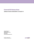
Network-Based Upgrade
An alternate method of upgrading the ReachNXT 100-8t uses an external DHCP/BootP and TFTP
server. This method may be more flexible for larger-scale deployments, since the firmware image can be
served from a single server. This method is illustrated in Figure 7.
The network-based upgrade relies on existing capabilities in the ExtremeXOS switch to connect
ReachNXT 100-8t units to an external server over a VLAN configured for this purpose. The VLAN to
use for this is conveyed to the ReachNXT 100-8t in the LLDP VLAN Name TLV. If the ReachNXT 100-8t
receives this TLV, it sends a BootP request on that VLAN, receives a BootP reply, and performs a TFTP
GET action to obtain the new firmware image file over the configured VLAN. If the server is not on the
same VLAN, the ExtremeEXOS BootP Relay capability can be used to re-direct BootP messages to the
server.
Figure 7: ReachNXT Network-Based Upgrade
DHCP/BootP Server
dhcp.conf
ExtremeXOS Switch
Port 26
range dynamic-bootp
10.10.10.128 10.10.10.254;
next-server 10.10.10.2;
filename
“Reach_100_8t_1.6.1.6.bin”
Port 25
LLDP, data
(untagged)
BootP reply
ReachMgmt
10.10.10.1
TFTP get, file
vid 20
transfer
TFTP Server (10.10.10.2)
/tftpboot/
Reach_100_8t_1.6.1.6.bin
BootP
ReachNXT 100-8t
RCH_003
The sections that follow describe the steps to complete the network-based firmware upgrade for an
installed ReachNXT 100-8t. The steps are:
1 Verify the connection to the ReachNXT 100-8t and current firmware version.
2 Create and configure VLANs for the ReachNXT upgrade.
3 Configure the DHCP/BootP Server.
4 Trigger the upgrade on the ReachNXT 100-8t.
5 Verify the upgrade.
18
ReachNXT 100-8t User Guide
Network-Based Upgrade
Verifying the ReachNXT 100-8t Connection and Firmware Version
Use the show lldp neighbors detailed command to report information about the connected
ReachNXT 100-8t and its current firmware version. The firmware version is indicated on the System
Description line, following the model name. In the following example, the firmware version 1.4.1.4 is
highlighted.
X250e-24x.17 # show lldp neighbors detailed
----------------------------------------------------------------------------LLDP Port 25 detected 1 neighbor
Neighbor: 00:04:96:1F:A8:00/9, age 25 seconds
- Chassis ID type: MAC address (4)
Chassis ID
: 00:04:96:1F:A8:00
- Port ID type: ifName (5)
Port ID
: "9"
- Time To Live: 120 seconds
- System Name: "Reach 100-8t 800284-00-01 0840G-00560"
- System Description: "Reach 100-8t 1.4.1.4"
Creating and Configuring VLANs for the ReachNXT Upgrade
If the ReachNXT 100-8t and the upgrade servers are on the same VLAN, follow the procedure in
“ReachNXT 100-8t and Upgrade Server on the Same VLAN” below. If the ReachNXT 100-8t and the
upgrade servers are on different VLANs, follow the procedure in “ReachNXT 100-8t and Upgrade
Server on Different VLANs” on page 20.
ReachNXT 100-8t and Upgrade Server on the Same VLAN
If the ReachNXT 100-8t and the upgrade servers are on the same VLAN, do the following to create and
configure a VLAN for the upgrade.
1 Create the VLAN and name it ReachMgmt. For example:
# create vlan ReachMgmt
NOTE
The name of the upgrade VLAN must be ReachMgmt.
2 Assign a VLAN tag to be used for the upgrade. For example:
# configure vlan ReachMgmt tag 20
3 Add each port number to which a ReachNXT 100-8t is connected. These ports must be added as
tagged ports. For example:
# configure vlan ReachMgmt add ports 25 tagged
4 Add the port to which the upgrade DHCP/BootP server and TFTP server are connected. This can be
tagged or untagged, depending on the server’s capability. For example:
# configure vlan default delete ports 26
# configure vlan ReachMgmt add ports 26 untagged
5 Configure an IP address for the ReachNXT upgrade VLAN. For example:
# configure vlan ReachMgmt ipaddress 10.10.10.1 255.255.255.0
ReachNXT 100-8t User Guide
19
Upgrading the ReachNXT 100-8t Firmware
6 Configure VLAN Name TLV advertisement for each port to which a ReachNXT 100-8t is connected.
(LLDP should already be enabled.) For example:
# configure lldp port 25 advertise vendor-specific dot1 vlan-name vlan ReachMgmt
ReachNXT 100-8t and Upgrade Server on Different VLANs
If the ReachNXT 100-8t and the upgrade server are on different VLANs, do the following to create and
configure two VLANs for the upgrade.
1 Create a VLAN for the ReachNXT 100-8t and name the VLAN ReachMgmt. For example:
# create vlan ReachMgmt
NOTE
The upgrade VLAN must be named ReachMgmt.
2 Assign a VLAN tag. This VLAN tag will be used for the upgrade. For example:
# configure vlan ReachMgmt tag 20
3 Add the port(s) to which ReachNXT 100-8t units are connected. These ports must be added as
tagged ports. For example:
# configure vlan ReachMgmt add ports 25 tagged
4 Configure an IP address for the ReachNXT 100-8t VLAN. For example:
# configure vlan ReachMgmt ipaddress 10.10.1.1 255.255.255.0
5 Enable IP forwarding for the ReachNXT 100-8t VLAN. For example:
# enable ipforwarding vlan ReachMgmt
6 Create a VLAN for access to the DHCP/BootP and TFTP servers. For example:
# create vlan server_vlan
7 Add one or more ports to which the servers are connected. These ports can be tagged or untagged,
depending on the server’s capability. For example:
# configure vlan default delete ports 26
# configure vlan server_vlan add ports 26 untagged
8 Configure an IP address for the upgrade VLAN. For example:
# configure vlan server_vlan ipaddress 10.10.10.1 255.255.255.0
# enable ipforwarding vlan server_vlan
9 Enable the BootP Relay function and add the DHCP/BootP server IP address. For example:
# configure bootprelay add 10.10.10.2 vr VR-Default
# enable bootprelay vr VR-Default
10 Set a proxy ARP entry for the TFTP server. (The ReachNXT 100-8t does not have a gateway route
and does not support the DHCP router option.) For example:
# configure iparp add proxy 10.10.10.2 255.255.255.255 vr VR-Default
11 Configure VLAN Name TLV advertisement for the port(s) to which the ReachNXT 100-8t units are
connected. (LLDP should already be enabled.) For example:
# configure lldp port 25 advertise vendor-specific dot1 vlan-name vlan ReachMgmt
20
ReachNXT 100-8t User Guide
Network-Based Upgrade
Configuring the DHCP/BootP Server
To configure the DHCP/BootP server:
1 Configure the DHCP/BootP server with an IP address on the same subnet as the ReachNXT upgrade
VLAN configured on the ExtremeXOS switch.
2 Download the ReachNXT firmware image file from the Extreme Networks website, and move it to
the /tftpboot directory of the TFTP server that will be used to distribute the file.
The image file is named according to the following format: Reach_100_8t_w.x.y.z.bin, where
w.x.y.z is the firmware version. The image file keep the with same name when it is downloaded to
the server, but can be renamed if necessary, as long as the name is 47 characters or fewer.
3 Configure the server for the ReachNXT upgrade VLAN as follows:
a Configure a range of IP addresses to be assigned for the ReachNXT 100-8t units to use for the
upgrade.
b Configure a server IP address, the IP address of the TFTP server use to get the firmware image
file
c
Configure the filename option to specify the name of the firmware image file as it is stored in
the /tftpboot directory on the TFTP server.
The following is a sample dhcp.conf entry for this example:
subnet 10.10.10.0 netmask 255.255.255.0 {
range dynamic-bootp 10.10.10.128 10.10.10.254;
default-lease-time 21600;
max-lease-time 43200;
next-server 10.10.10.2;
filename “Reach_100_8t_1.6.1.6.bin”;
Triggering the Upgrade on the ReachNXT 100-8t
The following events trigger a firmware upgrade on the ReachNXT 100-8t.
●
Initial connection and power-up
If LLDP is enabled on the ExtremeXOS switch, the DHCP server is configured, and the TFTP server
has the firmware image file, the firmware will be upgraded when the ReachNXT 100-8t is connected
and initializes.
●
Resetting inline power
If the ReachNXT 100-8t has already been connected and is powered by the ExtremeXOS switch, reset
it from the ExtremeXOS switch. For example:
# reset inline-power ports 10:48
●
Disabling and enabling the ExtremeXOS switch port
If the ReachNXT 100-8t has already been connected, disable and re-enable the port to trigger the
ReachNXT 100-8t to initiate the upgrade. For example:
# disable port 25
# enable port 25
ReachNXT 100-8t User Guide
21
Upgrading the ReachNXT 100-8t Firmware
Verifying the Upgrade
After the firmware has been upgraded, use the show lldp neighbors detailed CLI command to verify
that the new firmware version is installed.
# show lldp neighbors detailed
----------------------------------------------------------------------------LLDP Port 25 detected 1 neighbor
Neighbor: 00:04:96:1F:A8:00/9, age 19 seconds
- Chassis ID type: MAC address (4)
Chassis ID
: 00:04:96:1F:A8:00
- Port ID type: ifName (5)
Port ID
: "9"
- Time To Live: 120 seconds
- System Name: "Reach 100-8t 800284-00-01 0840G-00560"
- System Description: "Reach 100-8t 1.6.1.6"
22
ReachNXT 100-8t User Guide
4
Troubleshooting
This chapter describes techniques for troubleshooting the installation of the ReachNXT 100-8t port
extender. It includes the following sections:
●
Checking LLDP Status on page 23
●
Checking Power over Ethernet Status on page 23
●
Viewing EMS Messages on page 24
Checking LLDP Status
The ReachNXT 100-8t uses LLDP to communicate with the uplinked ExtremeXOS switch. It operates
only when it detects an ExtremeXOS switch connected to its uplink port via LLDP. The ReachNXT
100-8t sends LLDP Data Units (LLDPDUs) to the uplinked switch every 30 seconds, with a time to last
(TTL) of 120 seconds. The LLDPDUs contain TLVs for Chassis ID, Port ID, TTL, System Name, and
System Description.
LLDP must be enabled on the uplinked ExtremeXOS switch. On the switch, you can use the show lldp
neighbors command to get information about the downlinked ReachNXT 100-8t. The information
received from the ReachNXT 100-8t is similar to the following:
Slot-1 Stack.27 # show lldp neighbors detailed
-------------------------------------------------------------------------LLDP Port 4:1 detected 1 neighbor
Neighbor: 00:04:96:1F:A8:00/9, age 29 seconds
- Chassis ID type: MAC address (4)
Chassis ID
: 00:04:96:1F:A8:00
- Port ID type: ifName (5)
Port ID
: "9"
- Time To Live: 120 seconds
- System Name: "Reach 100-8t 800284-00-01 0840G-00560"
- System Description: "Reach 100-8t 1.6.1.6"
The System Name TLV includes the serial number of the ReachNXT 100-8t unit. The System Description
TLV includes the firmware version running on the ReachNXT 100-8t.
Checking Power over Ethernet Status
When the ReachNXT 100-8t is connected to the ExtremeXOS switch using the Gigabit uplink port (port
9), it can be powered through Power over Ethernet (PoE) supplied by the uplinked ExtremeXOS switch.
On the ExtremeXOS switch, PoE must be enabled for the port that is connected to the ReachNXT 100-8t.
ReachNXT 100-8t User Guide
23
Troubleshooting
To check the PoE status for a slot on an ExtremeXOS switch, use the show inline-power command. For
example:
BD-8810.1 # show inline-power slot 10
Slot
10
Inline-Power
Enabled
Firmware Status
Operational
Budgeted
Power (Watts)
50 W
Measured
Power (Watts)
6 W
Legacy
Disabled
To show detailed PoE information for a specific port, use the CLI command show inline-power info
detail. For example:
BD-8810.3 # show inline-power info detail ports 10:48
Port 10:48
Configured Admin State: enabled
Inline Power State
: delivering
MIB Detect Status
: delivering
Label
:
Operator Limit
: 15400 milliwatts
PD Class
: class0
Max Allowed Power
: 15.400 W
Measured Power
: 6.400 W
Line Voltage
: 48.0 Volts
Current
: 132 mA
Fault Status
: None
Detailed Status
: valid resistor detected, 802.3a
Priority
: low
Viewing EMS Messages
The ExtremeXOS Error Message System (EMS) includes messages specific to the ReachNXT 100-8t. Two
of these messages, lldp.ReachDtect and lldp.ReachRem, are visible in the system log by default, since
they are LLDP Informational messages, and LLDP has a report level of Informational by default.
Sample lldp.ReachDtect message:
09/18/2008 16:12:57.97 <Info:lldp.ReachDtect> Reach device detect for port 32, mac
00:04:96:1F:A8:03
Sample lldp.ReachRem message:
09/18/2008 16:12:45.44 <Info:lldp.ReachRem> Reach device remove for port 32, mac
00:04:96:1F:A8:03
The following message is reported by default when more than one Reach port extenders are detected as
connected to a port on the ExtremeXOS switch; the ExtremeXOS-based upgrade is supported only for
one directly attached Reach port extenders per port of the ExtremeXOS switch.
10/02/2008 19:09:34.07 <Noti:HAL.Reach.DtectLmt> More than one Reach device has been
detected on port 32.
24
ReachNXT 100-8t User Guide
A
Safety Information
WARNING!
Read the following safety information thoroughly before installing Extreme Networks products. Failure to follow this
safety information can lead to personal injury or damage to the equipment.
Only trained service personnel should perform service to Extreme Networks switches and their
components. Trained service personnel have read all related installation manuals, have the technical
training and experience necessary to be aware of the hazards to which they are exposed in performing a
task, and are aware of measures to minimize the danger to themselves or other persons.
This appendix includes the following sections:
●
Considerations Before Installing on page 25
●
Maintenance Safety on page 26
●
Cable Routing for LAN Systems on page 26
●
Selecting Power Supply Cords on page 27
●
Fiber Optic Ports—Optical Safety on page 27
Considerations Before Installing
Consider the following items before installing equipment.
●
The system is designed to operate in a typical environmentally controlled office environment.
Choose an indoor area that has the following characteristics:
■
Temperature- and humidity-controlled, such that the maximum ambient room temperature shall
not exceed 40ºC (104ºF)
■
Clean and free from airborne materials that can conduct electricity
■
Well ventilated and away from sources of heat including direct sunlight
■
Away from sources of vibration or physical shock
■
Isolated from strong electromagnetic fields produced by electrical devices
ReachNXT 100-8t User Guide
25
Safety Information
Maintenance Safety
When you perform maintenance procedures on Extreme Networks equipment, follow these
recommendations:
●
Use only original accessories and/or components approved for use with this system. Failure to
follow these instructions may damage the equipment or violate required safety and EMC
regulations.
●
The chassis cover should only be removed by Extreme Networks personnel. There are no customer
serviceable components in this system. Repairs to the system must be performed by an Extreme
Networks factory service technician.
●
Install all cables in a manner that avoids strain. Use tie wraps or other strain relief devices.
Cable Routing for LAN Systems
The Extreme Networks switches meet the requirements for LAN system equipment. LAN systems are
designed only for intra-building installations; that is, cable runs between devices must be in the same
building as the connected units.
This equipment can be connected between buildings if any one of the following conditions is true:
●
Cable runs between buildings are less then 140 feet long.
●
Cable runs between buildings are directly buried.
●
Cable runs between buildings are in an underground conduit, where a continuous metallic cable
shield or a continuous metallic conduit containing the cable is bonded to each building grounding
electrode system.
CAUTION
Failure follow these requirements for cable routing conditions may expose the user to electrical shock and expose
the unit to errors or damage.
WARNING!
The intra-building ports of the equipment or subassembly is suitable for connection to intrabuilding or unexposed
wiring or cabling only. The intra-building port(s) of the equipment or subassembly MUST NOT be metallically
connected to interfaces that connect to the outside plant (OSP) or its wiring. These interfaces are designed for use
as intra-building interfaces only (Type 2 or Type 4 ports as described in GR-1089-CORE, Issue 4) and require
isolation from the exposed OSP cabling. The addition of Primary Protectors is not sufficient protection in order to
connect these interfaces metallically to OSP wiring.
PoE Devices
When connecting power over Ethernet (PoE) devices to a PoE switch, all connections between the PoE
device and the switch must remain inside the same building and use a low-voltage power distribution
system per IEEE 802.3af.
26
ReachNXT 100-8t User Guide
Selecting Power Supply Cords
Selecting Power Supply Cords
Extreme Networks provides power adapters shipped with the product for use in the US and Canada.
The power adapter has several wall plug configurations and an option to use a two-prong power cord.
If a cord is desired, select a power supply cord that meets the following requirements:
●
Rated: 0.5 A minimum
●
Wall plug: Suitable for use in country of installation and approved by local regulatory authority
Fiber Optic Ports—Optical Safety
The following safety warnings apply to all optical devices used in Extreme Networks equipment that
are removable or directly installed in an I/O module or chassis system. Such devices include but are not
limited to gigabit interface converters (GBICs), small form factor pluggable (SFP) modules (or miniGBICs), XENPAK transceivers, and XFP laser optic modules.
WARNING!
Laser optic modules become very hot after prolonged use. Be careful when removing a laser optic module from the
chassis or option card. If the laser optic module is too hot to touch, disengage the laser optic module and allow it to
cool before removing it completely.
WARNING!
When working with laser optic modules, always take the following precautions to avoid exposure to hazardous
radiation.
●
Never look at the transmit LED/laser through a magnifying device while it is powered on.
●
Never look directly at a fiber port on the switch or at the ends of a fiber cable when they are powered on.
●
Invisible laser radiation can occur when the connectors are open. Avoid direct eye exposure to the beam
when optical connections are unplugged.
●
Never alter, modify, or change an optical device in any way other than suggested in this document.
SFP (Mini-GBIC), XENPAK, and XFP Regulatory Compliance
Extreme Networks pluggable optical modules meet the following regulatory requirements:
●
Class 1 Laser Product
●
EN60825-1+A2:2001 or later, European laser standard
●
FCC 21 CFR Chapter 1, Subchapter J in accordance with FDA & CDRH requirements
●
Application of CE Mark in accordance with 89/336/EEC EMC and 73/23/EEC Low Voltage
Directives
●
UL and/or CSA registered component for North America
●
47 CFR Part 15, Class A when installed into Extreme products
ReachNXT 100-8t User Guide
27
Safety Information
NOTE
Extreme Networks optical modules are tested to work in all supported Extreme Networks switches. We recommend
that all customers use Extreme Networks optical modules in their Extreme Networks switches. Extreme Networks
assumes no liability for third-party optical modules. Although Extreme Networks does not block third-party optical
modules, we cannot ensure that all third-party optical modules operate properly in all Extreme Networks switches.
The customer assumes all risks associated with using third-party optical modules in Extreme Networks switches.
28
ReachNXT 100-8t User Guide
Fiber Optic Ports—Optical Safety
Sicherheitshinweise
WARNUNG!
Vor der Installation der Produkte von Extreme Networks sind die nachfolgenden Sicherheitshinweise aufmerksam zu
lesen. Die Nichtbeachtung dieser Sicherheitshinweise kann zu Verletzungen oder Schäden an der Ausrüstung führen.
Installation, Wartung und Ausbau eines Switch, einer Grundplatte oder einer seiner Komponenten
dürfen nur von geschultem und qualifiziertem Servicepersonal durchgeführt werden! Geschulte und
qualifizierte Servicetechniker verfügen über die erforderliche technische Ausbildung und Erfahrung, um
mögliche Gefahren bei der Durchführung von Servicearbeiten zu erkennen und Maßnahmen zur
Minimierung der Gefahr für sich bzw. andere zu treffen.
Hinweise zur Installation
WARNUNG!
Beachten Sie vor der Installation der Ausrüstung folgende Punkte.
Stellen Sie sicher, dass die nachfolgend aufgeführten Bedingungen erfüllt sind:
●
Das System ist für den Einsatz in einer typischen Umgebung gemäß Telco-Vorgaben vorgesehen.
Wählen Sie einen Aufstellort mit den folgenden Eigenschaften:
■
Innenbereich mit Temperatur- und Feuchtigkeitsregelung, wobei die maximale Raumtemperatur
40°C (104ºF) nicht überschreiten darf.
■
Sauber und frei von elektrisch aufladbaren Teilchen in der Luft.
■
Ausreichende Belüftung und Abstand zu Wärmequellen, einschließlich direktem Sonnenlicht
■
Ausreichender Abstand zu Quellen, die Erschütterungen oder Schläge/Stöße hervorrufen können
■
Isolierung von starken elektromagnetischen Feldern, wie sie durch Elektrogeräte erzeugt werden
■
Sicherer, abgeschlossener Arbeitsbereich mit beschränktem Zugang, sodass nur geschultes und
qualifiziertes Servicepersonal Zugriff auf das Gerät hat
■
Die Ausrüstung im unteren Teil des Gestells installieren, um zu vermeiden, dass der obere Teil
des Gestells zu schwer wird.
●
In für elektrische Stürme anfälligen Gebieten wird empfohlen, das System an einen
Spannungsstoßunterdrücker anzuschließen.
●
Auf allen Seiten für mindestens 7,5 cm (3") Abstand sorgen, um eine ausreichende Belüftung zu
gewährleisten. Die Lufteinlassöffnung an den vorderen, seitlichen und hinteren Entlüftungsgittern
nicht blockieren. Das System nicht in der Nähe von Wärmequellen aufstellen.
●
Sicherstellen, dass die Ausrüstung in einem Bereich aufgestellt wird, der den Spezifikationen für
Leistungsaufnahme und Wärmeabstrahlung der Komponenten entspricht.
●
Sicherstellen, dass Ihre Netzteile die Anforderungen an die Strom- oder Wechselstromversorgung
vor Ort für alle Netzwerkgeräte erfüllen.
●
Bei den Extreme-Produkten handelt es sich um digitale Geräte der Klasse A gemäß Teil 15 der FCCRichtlinien und anderen internationalen Richtlinien. Der Gerätebetrieb unterliegt den folgenden
Voraussetzungen: (1) Das Gerät kann schädliche Interferenzen verursachen, und (2) das Gerät muss
jede empfangene Interferenz zulassen, einschließlich einer Interferenz, die einen unerwünschten
Betrieb verursachen kann.
ReachNXT 100-8t User Guide
29
Safety Information
Installation von Netzteilen
WARNUNG!
Bei der Installation sämtlicher Netzteile von Extreme Networks muss sichergestellt werden, dass die nachfolgend
aufgeführten Anforderungen erfüllt sind. Angaben zu Nennleistung und Leistungsbedarf finden sich in den
Installationsanweisungen für das jeweilige Netzteil (Power Supply Unit, PSU).
Folgende Anforderungen müssen unbedingt erfüllt sein:
●
Wenn der mit Wechsel- oder Gleichstrom betriebene Switch von Extreme Networks mit einem
externen grünen/gelben Erdungskabel ausgestattet ist, dann muss zunächst dieses Erdungskabel
zwischen der Grundplatte und einem geeigneten Erdungspunkt angeschlossen werden, bevor andere
Verbindungen zum Gerät hergestellt werden; dies gilt auch für den Anschluss an das Wechsel- bzw.
Gleichstromnetz. Beim Ausbau des Geräts aus dem Gestell muss das Erdungskabel als letztes
getrennt werden.
●
Netzteile nur an vorschriftsmäßig geerdete Steckdosen anschließen, um die Gefahr elektrischer
Schläge zu vermeiden und die Konformität mit internationalen Sicherheitsnormen zu gewährleisten.
●
Nur Stromkabel verwenden, die für den Einsatz in dem jeweiligen Land zugelassen sind.
Wechselstromkabel dürfen nicht manipuliert werden.
●
Die Wandsteckdose muss in der Nähe der Anlage installiert und leicht zugänglich sein, um eine
schnelle Trennung vom Netz zu ermöglichen.
●
Spannung und Frequenz der Steckdose müssen den elektrischen Nenndaten des Systems
entsprechen. Das Gebäude bzw. die Stromquelle muss mit einem Überlastschutz ausgestattet sein.
●
Einen Spannungsstoßunterdrücker, einen Netzfilter oder eine unterbrechungsfreie Stromversorgung
verwenden, um das System vor einer vorübergehenden Zu- oder Abnahme der elektrischen Leistung
zu schützen.
●
Bei laufendem Betrieb austauschbare Netzteile: Das Netzteil vorsichtig, nicht mit Kraft in das
Aufnahmefach einsetzen.
●
Bei Einsatz mehrer Netzteile in einem Switch sind die Netzteile jeweils an unterschiedliche,
unabhängige Stromquellen anzuschließen. Auf diese Weise ist bei einem Ausfall einer einzelnen
Stromquelle nur das daran angeschlossene Netzteil betroffen. Wenn alle Netzteile eines einzelnen
Switch an dieselbe Stromquelle angeschlossen sind, ist der gesamte Switch für einen Ausfall der
Stromversorgung anfällig.
Leistungsspezifikationen für Netzteile von Extreme Networks finden sich in Anhang B dieses
Dokuments oder im Netzteil-Datenblatt unter http://www.extremenetworks.com.
Wartungssicherheit
Folgende Vorsichtsmaßnahmen müssen getroffen werden:
30
●
Nur für den Einsatz mit diesem System zugelassene Originalzubehörteile bzw. -komponenten
verwenden. Die Nichtbeachtung dieser Anweisungen kann zu Schäden an der Ausrüstung oder
sogar zu einem Verstoß gegen die erforderlichen Sicherheitsbestimmungen und EMV-Vorschriften
führen.
●
Die Abdeckung der Grundplatte darf nur durch Personal von Extreme Networks entfernt werden.
Das System enthält keine vom Kunden zu wartenden Komponenten. Reparaturen am System sind
von einem Werkstechniker von Extreme Networks durchzuführen.
ReachNXT 100-8t User Guide
Fiber Optic Ports—Optical Safety
●
Der An-/Aus-Schalter des Systems darf nicht die gesamte Stromversorgung zum System
unterbrechen. Zur Unterbrechung der Wechselstromversorgung zum System müssen alle Stromkabel
aus den Wandsteckdosen gezogen werden. Das Stromkabel dient zur Trennung von der
Netzstromversorgung.
●
Vor dem Entfernen der Rückwand eines Extreme Networks-Switch muss die gesamte Stromzufuhr
unterbrochen werden.
●
Vor der Aufnahme von Arbeiten in der Nähe von Stromquellen alle Stromkabel abziehen, sofern
nicht im Rahmen eines Wartungsverfahrens anders vorgegeben.
●
Beim Umgang mit Modulen, optischen Geräten, Netzteilen oder anderen modularen Zubehörteilen
das ESD-Schutzarmband anlegen, um das Risiko einer Beschädigung der Geräte durch
elektrostatische Entladungen zu verringern. Das Armband zum Schutz elektrostatisch gefährdeter
Bauteile (ESB) grundsätzlich an der Grundplatte befestigt lassen, damit es beim Umgang mit diesen
Bauteilen immer zur Hand ist.
●
Alle Kabel so verlegen, dass übermäßige Belastungen vermieden werden. Kabelbinder oder
Zugentlastungsklemmen verwenden.
●
Ein Stromkabel bei Anzeichen von Beschädigungen unverzüglich austauschen.
Allgemeine Sicherheitsvorkehrungen
Folgende Richtlinien sind unbedingt zu befolgen:
●
Keine Gegenstände heben, die möglicherweise zu schwer sind.
●
Bei einer Installation in einem Gestell darauf achten, dass schwere Geräte unten im Gestell eingebaut
werden, um Gefahren durch Umkippen zu vermeiden.
●
Bei Summit Desktop-Switches keinen Monitor oder andere Gegenstände auf die Anlage stellen. Die
Abdeckung der Grundplatte ist nicht darauf ausgelegt, Gewicht zu tragen.
●
Nur Werkzeuge und Ausrüstung verwenden, die sich in einwandfreiem Zustand befinden. Keine
Ausrüstung verwenden, die sichtbare Beschädigungen aufweist.
●
Verlegen von Kabeln: Kabel so verlegen, dass keine Schäden entstehen oder Unfälle, z. B. durch
Stolpern, verursacht werden können.
Auswahl der Stromkabel
Je nachdem, welchen Switch Sie erworben haben, werden die Wechselstromnetzteile von Extreme
Networks entweder nur mit einem 110-VAC-Kabel oder mit einem 110-VAC-Kabel und einem 208/220VAC-Kabel geliefert. Die von Extreme Networks gelieferten Stromkabel sind nur für den Einsatz in den
Vereinigten Staaten und Kanada ausgelegt und zugelassen. Stromkabel für den Einsatz außerhalb der
Vereinigten Staaten und Kanada werden normalerweise von einem Drittanbieter geliefert und müssen
die folgenden Anforderungen erfüllen:
●
Die Stromkabel müssen offiziell für das Land zugelassen sein, in dem sie verwendet werden sollen.
●
Die Stromkabel müssen mit einem für das Einsatzland zugelassenen Wandsteckkontakt mit der
geeigneten Nennleistung ausgerüstet sein.
●
Die Konfiguration der Steckvorrichtung (die Steckverbindung zur Einheit, nicht zur Wandsteckdose)
muss für eine Gerätesteckdose gemäß EN60320/IEC320-C14 ausgeführt sein.
●
Die Länge der Stromkabel muss weniger als 5 m (15 Fuß) betragen.
●
Die Mindestspezifikation für das flexible Kabel lautet:
ReachNXT 100-8t User Guide
31
Safety Information
●
■
Nr. 18 AWG (0,823 mm2) für Einheiten mit einem Bemessungsstrom von weniger als 10 A,
oder
■
Nr. 18 AWG (0,823 mm2) bis 2 m Länge für Einheiten mit einem Bemessungsstrom von 10 A
oder höher, oder
■
Nr. 16 AWG (1,0 mm2) bis 5 m Länge für Einheiten mit einem Bemessungsstrom von 10 A
oder höher
Bei allen Kabeln muss es sich um 3-adrige Kupferleiter vom Typ SVT oder SJT, HAR oder einen
äquivalenten Typ handeln.
Verwenden Sie immer ein Wechselstromkabel, das den Vorschriften Ihres Landes entspricht. Erkundigen
Sie sich über die örtlichen Vorschriften für Elektroinstallationen und fragen Sie bei den zuständigen
Aufsichtsbehörden nach den Anforderungen an Stromkabel. Nähere Angaben zu den
Leistungsspezifikationen von Netzteilen finden sich unter http://www.extremenetworks.com oder in
Anhang B dieses Dokuments.
Lichtleiteranschlüsse: Optische Sicherheit
WARNUNG!
Beim Umgang mit Lichtleitermodulen sind folgende Vorsichtsmaßnahmen zu beachten:
●
Niemals durch ein Vergrößerungsgerät auf die übertragende LED/den Laser schauen, wenn diese(r)
eingeschaltet ist.
●
Niemals direkt auf einen Lichtleiteranschluss am Switch oder auf die Enden eines Faserkabels schauen,
wenn diese eingeschaltet sind.
●
Bei offenen Anschlüssen kann es zu unsichtbarer Laserstrahlung kommen. Direkter Augenkontakt mit dem
Strahl ist zu vermeiden.
●
Ein optisches Gerät niemals auf andere Weise verändern oder modifizieren als in diesem Dokument
angegeben.
Einhaltung behördlicher Vorschriften durch SFP (Mini-GBIC), XENPAK und XFP
32
●
Laserprodukt der Klasse 1
●
EN60825-1+A2:2001 oder jünger, Europäische Richtlinie für Lasersysteme
●
Anwendung der CE-Kennzeichnung gemäß der Richtlinien 89/336/EWG EMV und 73/23/EWG für
Niederspannungsgeräte
ReachNXT 100-8t User Guide
B
Technical Specifications
This appendix provides technical specifications for the ReachNXT 100-8t port extender and related
components:
Table 3: ReachNXT 100-8t Technical Specifications
Physical Dimensions
Height: 1.34 inches (3.4 cm)
Width: 8.66 inches (22 cm)
Depth: 5.89 inches (15 cm)
Weight
1.1 lb (0.5 kg)
Packaged Dimensions
Height: 2.63 inches (6.68 cm)
Width: 14 inches (35.56 cm)
Depth: 7.25 inches (18.42 cm)
Packaged Weight
2 lb (0.91 kg)
Power Specifications
Optional AC power adapter
Manufacturer: Leader Electronics, Inc.
Model number: IU18-2120125-WP
Nominal Input Ratings: 100 – 240V, 50/60Hz
Nominal Input Current: 0.5A
Nominal Output Ratings: 12V
Nominal Output Current: 1.25A
Power dissipation
Powered by AC adapter: 7 W
Powered by PoE: 8.5 W
Acoustic sound
Noise: none (unit has no fan)
Safety Standards
North America
UL 60950-1, Listed Accessory
cULus Listed Accessory, Equivalent to CAN/CSA-C22.2 No.
60950-1-00 (Canadian Safety of ITE)
Europe
Low Voltage Directive (LVD)
TUV GS Mark (German Notified Body)
EN60950-1:2001 (European Safety of ITE)
International
CB Report & Certificate per IEC 60950-1:2001 Country Deviations
Country-specific
NOM/NYCE, Product Safety & EMC Approval (Mexico)
AS/NZS 3260, ACA DoC, Safety of ITE (Australia/New Zealand)
Laser Safety Standards (SFP Modules Only)
North America
FCC 21 CFR subpart (J) (Safety of Laser Products)
CDRH Letter of Approval (US FDA Approval)
Europe
EN60825-1:+A2:2001 (European Safety of Lasers)
EMI/EMC Standards
North America EMC for ITE
ReachNXT 100-8t User Guide
FCC CFR 47 part 15 Class B (USA)
ICES-003 Class B (Canada)
33
Technical Specifications
Table 3: ReachNXT 100-8t Technical Specifications (continued)
European EMC standards
EN 55022: 2006 Class B
EN 55024 A2:2003
EN61000-3-2 8-2006 (Harmonics)
EN61000-3-3 1995+A2:2005 (Flicker)
2004/108/EC EMC Directive
International EMC certifications
CISPR 22:2006 Ed 5.2, Class B (International Emissions)
CISPR 24 A2:2003 (International Immunity)
IEC/EN 61000-4-2 Electrostatic Discharge
IEC/EN 61000-4-3 Radiated Immunity 10V/m, Criteria A
IEC/EN 61000-4-4 Transient Burst
IEC/EN 61000-4-5 Surge
IEC/EN 61000-4-6 Conducted Immunity
IEC/EN 61000-4-11 Power Dips & Interruptions
Country-specific
VCCI Class B (Japan Emissions)
ACMA (C-Tick) via CISPR 22:2006 (Australia & New Zealand)
CNS 13438:1997 Class B (BSMI-Taiwan)
KCC Mark, KN22, KN24, Class B (North Korea)
NOM/NYCE, Product Safety & EMC Approval (Mexico)
CCC (China)
Telecom Standards
ETSI
ETSI
IEEE
IEEE
IEEE
IEEE
IEEE
EN 300 386:2001 (EMC Telecommunications)
EN 300 019 (Environmental for Telecommunications)
802.3 Media Access Standards
802.3ab 1000BASE-T
802.3af PoE/PD
802.3z 1000BASE-X
802.1AB – LLDP Link Layer Discovery Protocol
Environmental Data
34
Environmental Standards
EN/ETSI 300 019-2-1 v2.1.2 - Class 1.2 Storage
EN/ETSI 300 019-2-2 v2.1.2 - Class 2.3 Transportation
EN/ETSI 300 019-2-3 v2.1.2 - Class 3.1e Operational
EN/ETSI 300 753 (1997-10) - Acoustic Noise
ASTM D3580 Random Vibration Unpackaged 1.5G
Operating conditions
Temperature range: 0° C to 40° C (32° F to 104° F)
Relative Humidity: 10 - 93%
Altitude: 0 to 3,000 meters (9,850 feet)
Shock (half sine): 30 m/s2 (3 g), 11 ms, 60 shocks
Office Vibration (In Rack): 5-100-5 Hz @ 2/10g, 0-Peak, 1 Oct./min.
Random Vibration: 3-500 Hz @ 1.5g rms
Storage & transportation conditions
(packaged)
Temperature: –40° C to 70° C (–40° F to 158° F)
Relative Humidity: 10 - 90%
Packaged shock (half sine): 180 m/s2 (18 g), 6 ms, 600 shocks,
(package < 50kg)
Packaged random vibration: 5 to 20 Hz @ 1.0 ASD w/–3 dB/oct.
from 20 to 200 Hz
14 drops minimum on sides & corners @ 39.4” (<15 kg box)
ReachNXT 100-8t User Guide
Index
A
I
AC power adapter
model number, 9
specifications, 33
with SFP uplink connection, 11
AC power, connecting, 12
application, typical, 5
authentication, MAC, 6
initial power-up, 15
initializing the Reach 100-8t, 14
installation, 11
installation requirements, 11
B
BootP server, 18
K
Kensington lock, 9, 11
L
C
laser safety, 33
LEDs, 7
Link Layer Discovery Protocol (LLDP), 6, 23
combination port, 9
configuring PoE, 14
connecting AC power, 12
M
D
DHCP/BootP server, 18, 21
disabled ports, 6
downloading new image, 16
E
EMI/EMC standards, 33
EMS messages, 24
enabled ports, 6
environmental standards, 34
EPICenter network management software, 7
ExtremeXOS version, 6
ExtremeXOS-based firmware upgrade, 15
F
firmware upgrade
ExtremeXOS-based, 15
network-based, 18
overview, 7
triggering, 15
firmware version
identifying, 15
verifying installation, 16, 19
ReachNXT 100-8t User Guide
MAC authentication, 6
magnet mounting kit, 12
messages, EMS, 24
MGMT LED, 8
minimum software, 6, 11
model number, AC adapter, 9
monitoring the Reach 100-8t, 7
N
network-based firmware upgrade, 7, 18
new image, downloading, 16
O
operating conditions, 34
operation requirements, 6
optical module regulatory compliance, 27
P
physical specifications, 33
PoE
configuring, 14
connection, 9
status, checking, 23, 24
PoE support, 6
port LEDs, 8
port, uplink, 9, 14
ports, 5
35
power
connecting AC adapter, 12
using PoE, 6
power cord, 27
power requirements, SFP uplink port, 6
power socket, 12
power specifications, 33
power-up, initial, 15
PWR LED, 8
R
received TLVs, 15
requirements
firmware upgrade, 15
installation, 11
minimum software, 6
operation, 6
power, 11
reset button, 9
reset inline-power command, 15
V
VLAN for firmware upgrade, 19
VLAN Name TLV, 18
W
wall mounting, 12
X
XMOD package
downloading, 16
name, 15
uninstalling, 18
S
safety standards, 33
safety, laser, 33
security lock, 9
SFP support, 9
SFP uplink port, 6
show lldp neighbors command, 23
software, minimum, 6, 11
specifications, 33
status, PoE, 23, 24
supported software versions, 6
switch-based firmware upgrade, 7
T
telecom standards, 34
TFTP server, 18
TLVs
received, 15, 18
transmitted, 7
transmitted TLVs, 7
triggering a firmware upgrade, 15
troubleshooting suggestions, 23
typical application, 5
U
upgrade trigger, 15
upgrade VLAN, 19
uplink port, 9, 14
uplinked switch, 6
36
ReachNXT 100-8t User Guide