1
822-1XRT, 882-EVDO
CDMA Serial Cellular Data Modem & IP Router
822-1XRT-XXX and 882-EVDO-XXX
CDMA Cellular Data Modem & IP Router
User Manual
001-0003-822
Revision 1; February 2008
REVISION HISTORY
Released February 2008
TABLE OF CONTENTS
SECTION 1 – PREFACE
PREFACE........................................................................................................ 5
Copyright Notice............................................................................................................. 5
Modem Use.................................................................................................................... 5
Interference Issues ......................................................................................................... 5
Mobile Application Safety ................................................................................................. 6
SECTION 2 – PRODUCT OVERVIEW ...................................................................................... 7
Module Identification....................................................................................................... 7
General Description ........................................................................................................ 7
Features and Benefits...................................................................................................... 7
Catalog Part Number Breakdown....................................................................................... 7
External Connections ...................................................................................................... 8
Front panel connections ............................................................................................... 8
Back panel connections ................................................................................................ 9
RS-232 Serial Port Integration Parameters...................................................................... 9
Accessories & Options ................................................................................................ 10
SECTION 4 – GETTING STARTED
STARTED........................................................................................ 11
Package Contents ......................................................................................................... 11
Local PC Ethernet Configuration ...................................................................................... 11
Accessing the Modem’s Homepage .................................................................................. 13
Provisioning ................................................................................................................. 14
Modem Network Connection ........................................................................................... 14
Local PC Serial Communication ....................................................................................... 16
SECTION 5 – PROVISIONING
PROVISIONING............................................................................................. 18
Provisioning Information: Current Status ......................................................................... 18
Activation: Manual-Entry Activation................................................................................. 19
Activation: OTASP and IOTA.......................................................................................... 19
SECTION 6 – CARRIER SPECIFIC PROVISIONING INFORMATION ........................................... 20
Verizon Wireless Subscribers .......................................................................................... 20
Sprint PCS Subscribers .................................................................................................. 21
Alltel Subscribers.......................................................................................................... 22
Telus (Canada) Subscribers............................................................................................ 23
SECTION 7 – LAN CONFIGURATION
CONFIGURATION.................................................................................... 24
LAN Configuration......................................................................................................... 24
DNS Resolving ............................................................................................................. 25
DHCP Configuration ...................................................................................................... 25
PPPoE Setup ................................................................................................................ 25
Remote Administration .................................................................................................. 29
SECTION 8 – PORT FORWARDING SETTINGS
SETTINGS....................................................................... 30
Port Forwarding Support................................................................................................ 30
Port Forwarding Configuration ........................................................................................ 30
SECTION 9 – ROUTING
ROUTING..................................................................................................... 32
RIP Routing ................................................................................................................. 32
VRRP Configuration....................................................................................................... 32
Static Routes ............................................................................................................... 33
SECTION 10 – SIMPLE NETWORK MANAGEMENT PROTOCOL (SNMP)
(SNMP)....................................... 34
SNMP Configuration ...................................................................................................... 34
SECTION 11 – DYNAMIC DNS ............................................................................................ 35
NO-IP Configuration ...................................................................................................... 35
SECTION 12 – FIRMWARE UPDATE ..................................................................................... 37
Current Firmware Information ........................................................................................ 37
Download New Firmware ............................................................................................... 37
SECTION 13 – SERIAL SETTINGS ....................................................................................... 38
Serial Settings ............................................................................................................. 38
PAD Settings................................................................................................................ 39
SECTION 14 – SERIAL INTERFACE COMMUNICATION ............................................................ 40
TABLE OF CONTENTS
SECTION 15 – SPECIFICATIONS ........................................................................................
General Specifications ...................................................................................................
Mechanical Specifications...............................................................................................
SECTION 16 – ABBREVIATIONS .........................................................................................
SECTION 17 – SERVICE AND SUPPORT ...............................................................................
Product Warranty, RMA and Contact Information...............................................................
RMA Request ...............................................................................................................
Product Documentation .................................................................................................
Technical Support .........................................................................................................
APPENDIX 1 – WARRANTY STATEMENT ...............................................................................
44
44
45
46
47
47
47
47
47
48
SECTION 1 – PREFACE
Copyright Notice
©2008 CalAmp. All Rights Reserved.
This manual covers the operation of the CalAmp 822-1XRT and 882-EVDO Cellular Data
Modem IP Routers. Specifications described are typical only and are subject to normal
manufacturing and service tolerances.
CalAmp reserves the right to modify the equipment, its specification or this manual without
prior notice, in the interest of improving performance, reliability, or servicing. At the time of
publication all data is correct for the operation of the equipment at the voltage and/or
temperature referred to. Performance data indicates typical values related to the particular
product.
No part of this documentation or information supplied may be divulged to any third party
without the express written consent of CalAmp.
Products offered may contain software which is proprietary to CalAmp. The offer or supply
of these products and services does not include or infer any transfer of ownership.
Modem Use
The 822-1XRT and 882-EVDO modems are designed and intended for use in fixed and
mobile applications. “Fixed” assumes the device is physically secured at one location and
not easily moved to another location. Please keep the cellular antenna of the 8221XRT/882-EVDO modem at a safe distance from your head and body while the modem is in
use (see below).
Important
Maintain a distance of at least 20 cm (8 inches) between the transmitter’s antenna and any
person while in use. This modem is designed for use in applications that observe the 20 cm
separation distance.
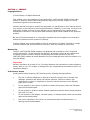
Interference Issues
Avoid possible radio frequency (RF) interference by following these guidelines:
•
The use of cellular telephones or devices in aircraft is illegal. Use in aircraft may
endanger operation and disrupt the cellular network. Failure to observe this
restriction may result in suspension or denial of cellular services to the offender,
legal action or both.
•
Do not operate in the vicinity of gasoline or diesel-fuel pumps unless use has been
approved and authorized.
•
Do not operate in locations where medical equipment that the device could interfere
with may be in use.
•
Do not operate in fuel depots, chemical plants, or blasting areas unless use has been
approved and authorized.
•
Use care if operating in the vicinity of protected personal medical devices, i.e.,
hearing aids and pacemakers.
001-0003-822 Rev 1
Page 5 of 48
•
Operation in the presence of other electronic equipment may cause interference if
equipment is incorrectly protected. Follow recommendations for installation from
equipment manufacturers.
Mobile Application Safety
•
Do not change parameters or perform other maintenance of the 822-1XRT/882EVDO modem while driving.
•
Road safety is crucial. Observe National Regulations for cellular telephones and
devices in vehicles.
•
Avoid potential interference with vehicle electronics by correctly installing the
822-1XRT/882-EVDO modem. CalAmp DataCom recommends installation by a
professional.
001-0003-822 Rev 1
Page 6 of 48
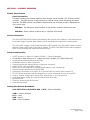
SECTION 2 – PRODUCT OVERVIEW
Module Identification
Label Information
The label contains the CalAmp DataCom part number, serial number, FCC ID and the ESN
numbers. The ESN number is required by your cellular carrier when activating your data
contract. The ESN number is provided in decimal and Hex formats; format is dependent on
your carrier type.
ESN Dec: The Electronic Serial Number of the cellular module in decimal format.
ESN Hex: Same number as above but in a special HEX format.
General Description
The 822-1XRT/882-EVDO Cellular Data Modem & IP Router from CalAmp is the ideal solution
for a wide range of cellular data network serial and ethernet connectivity requirements.
The 822-1XRT modem version features CDMA 1xRTT speeds. The 882-EVDO modem version
features CDMA 1xRTT and EV-DO Rev A speeds. The 822-1XRT/882-EVDO modem supports
both circuit-switched and packet-switched services.
Features and Benefits
1xRTT Dynamic or Static IP (Mobile IP/DMU) – Carrier Dependent
EV-DO Rev A data rates up to 3.1 Mbps (Rx) and 1.8 Mbps (Tx) (882-EVDO only)
Inbound and Outbound Ethernet Routing
Embedded Linux on ARM 9 processor
Internet access and web browsing via Ethernet connector
SNMP, PPPoE, RIP, and VRRP support
DHCP Server and Inbound port mapping/translation (Port Forwarding)
Modem Domain Names with Dynamic DNS
Inbound IP termination with Static IP or Reverse DNS for lookup with Dynamic IP
TCP/IP Packet assembler and dis-assembler for serial connected devices using ASCII
Local or remote configuration using HTML web server or AT command set
Dual Band Digital CDMA 800 MHz and CDMA PCS 1900 MHz
Optional AGPS
Diversity antenna (882-EVDO only)
USB Host Controller
Catalog Part Number Breakdown
822-1XRT-XXX or 882-EVDO-XXX
(XXX = Carrier Identifier)
VZW = Verizon Wireless
ALT = Alltel
SPN = Sprint
TMC = Telus (Canada)
001-0003-822 Rev 1
Page 7 of 48
External Connections
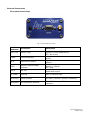
Front panel connections
Fig. 2.1 822-1XRT Front Panel
Panel
Indicator
Connection
SVC TYPE
Service Type
TX/RX
Transmit/Receive
DCD
Data Carrier Detect
RSSI
Receive Signal Strength
Indicator
Serial
RS-232
RF (SMA)
Antenna
Main RF antenna input
AUX(SMA)
AGPS Antenna
822-1XRT (optional connector installation)
AUX(SMA)
Diversity/AGPS Antenna
882-EVDO Diversity/AGPS antenna
connector
Description
Solid = Higher speed service
Blinking = Lower speed service
Off = No service
Indication of data transmission or reception
activity
Signals router’s connection on the cellular
network
Solid = strong
Blinking = medium
Off = poor
Unit configuration alternative for serialbased data transfer
001-0003-822 Rev 1
Page 8 of 48
Back panel connections
Fig. 2.2 822-1XRT/882-EVDO Back Panel
Panel
Indicator
Connection
Ethernet
RJ-45 Ethernet
USB Host
USB
Description
Interface for Ethernet connection to devices
through network hub or router
Interface for external devices (i.e., memory
drives or GPS devices)
Reset
Momentary switch for unit reset
PWR LED
Power indicator
PWR Jack
2.1x5.5mm plug
Interface for power plug (9-28VDC)
RS-232 Serial Port Integration Parameters
Table 2.1 provides the serial cable design information to integrate the 822-1XRT/882-EVDO into
your system.
Table 2.1 Standard RS-232 DE-9 Pin out
Pin
1
2
3
4
5
6
7
8
9
Name
CD
RX
TX
DTR
GND
DSR
RTS
CTS
RI
Direction
«—
«—
—»
—»
«—
—»
«—
«—
Note: Direction is
Description
Carrier Detect
Receive Data
Transmit Data
Data Terminal Ready
System Ground
Data Set Ready
Request to Send
Clear to Send
Ring Indicator
DTE relative DCE.
001-0003-822 Rev 1
Page 9 of 48
Table 2.2 Default RS-232 Communication Parameters
Bits Per Second
Data Bits
Parity
Stop Bits
Flow Control
115,200
8
None
1
None
Accessories & Options
Accessory/Option
Description
Order Number
Antenna
4” Rubber Duck Antenna
3” Mag Mount Antenna
L2-ANT0001
L2-ANT0003
Power Supply
110 VAC input
DC Power Cable
L2-PWR0001
L2-PWR0002
Interface Cables
Serial Cable
Ethernet cross-over cable
L2-CAB0002
L2-CAB0006
AGPS Option
(822-1XRT only)
Installed AGPS antenna connector
823-7500-502
Primary Antenna
The primary and optional AGPS antenna connections on the 822-1XRT/882-EVDO modem are
female connectors, therefore you must purchase an antenna with a SMA male connector. Do not
select a SMA antenna with “reverse polarity” or RP-Male. When using a direct mount or “rubber
duck” antenna, choose the antenna specific to your band requirements. Mounting options and
cable lengths are user’s choice and application specific.
AUX Antenna
The AUX antenna is a female SMA connector which can be optionally install on the 822-GPRS
modem to be used for AGPS.
The AUX antenna connector is installed as standard on the 882-EVDO modem and can be used
for Diversity, AGPS, or both depending on the antenna attached and the modem programming.
The modem, by default, sets the AUX input as a Diversity antenna.
001-0003-822 Rev 1
Page 10 of 48
SECTION 4 – GETTING STARTED
The 822-1XRT/882-EVDO modem can be configured via HTML web pages or AT commands on the
serial port. You will need a CDMA Cellular account. For TCP/IP please request a 1xRTT (822-1XRT) or
EVDO (882-EVDO) Account with Mobile IP and optionally Static IP or Simple IP (SIP). This is carrier
dependent.
The modem is configured with default settings and is ready to be configured via HTML. You may
need to activate the modem with your carrier to start using it. The default settings are programmed
for most operations.
Package Contents
•
•
822-1XRT/882-EVDO cellular data modem (specific to CDMA cellular provider)
Information Card
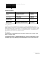
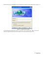
Local PC Ethernet Configuration
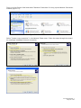
The 822-1XRT/882-EVDO modem is configured via the Internet which automatically allows your
computer to obtain the proper IP address. For Windows XP users, select Start -> Control Panel ->
Network Connections. Right click “Local Area Connection” and select “Properties” to open the
configuration dialog box for Local Area Connection. See Figure 4.1.
Figure 4.1: Local PC Network Connections Screen
001-0003-822 Rev 1
Page 11 of 48
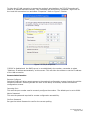
Find and select “Internet Protocol (TCP/IP)” from the list box and then click the “Properties” button
(Figure 4.1). The TCP/IP configuration window will pop up, refer to Figure 4.2. Under the General
tab, select radio button “Obtain an IP address automatically” and “Obtain DNS server address
automatically” (Figure 4.2). Click the OK button to close TCP/IP configuration window. Click the
Close button to complete the computer preparation for the 822-1XRT/882-EVDO modem.
Figure 4.2: Internet protocol (TCP/IP) properties screen
Connect an antenna to the RF connector on the front panel of the 822-1XRT/882-EVDO modem.
Connect the Ethernet cross-over cable into the 822-1XRT/882-EVDO modem’s Ethernet Port and
plug the other end into the network port of your PC. Connect the Power Adapter to the 8221XRT/882-EVDO modem and plug into a proper AC power socket. The Power LED on the panel
should activate. The Service LED (SVC TYPE) and RSSI LED will light green to indicate the 8221XRT/882-EVDO has finished starting up and is functioning.
001-0003-822 Rev 1
Page 12 of 48
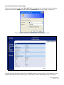
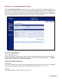
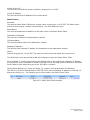
Accessing the Modem’s Homepage
Start your web browser and enter 192.168.1.50 in the address bar. A login screen should appear,
enter the User Name: admin and the Password: password and click OK. Refer to Figure 4.3.
Figure 4.3: 822-1XRT/882-EVDO browser connection login screen
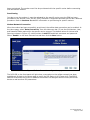
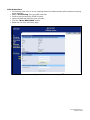
Figure 4.4: 822-1XRT/882-EVDO configuration Home page
The PPP status on the Home page will show DOWN because the new device is not enabled. Also, the
MDN/MTN or MIN/IMSI lines may show an invalid phone number indicating that the unit has not
001-0003-822 Rev 1
Page 13 of 48
been provisioned. The modem must first be provisioned with the specific carrier before connecting
with the cellular network.
Provisioning
In order to use the modem, it must be activated by the specific carrier once the ESN has been
provided for the account. Over-The-Air (OTA) activation is supported and each carrier has a different
procedure. Refer to Sections 5 and 6 for information on provisioning for specific carriers.
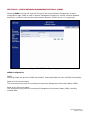
Modem Network Connection
After the modem has been successfully provisioned, the cellular data connection can be enabled. At
the Home page, select “Data Connection” from the side menu bar. Fill out the Dial Number, User,
and Password fields required for the specific carrier account. The default values for Verizon and
Sprint are shown in Figure 4.5, a dial number of atd#777 and blank username and password.
Select “Enable” on the Auto Connect line and then click the Save button.
Figure 4.5: Data Connection configuration page
The DCD LED on the front panel will light when a connection to the cellular network has been
established. Go back to the Home page to verify the PPP Status is UP (Figure 4.6). The PPP IP
Address field shows the current IP address the network has assigned the 822-1XRT/882-EVDO
device as well as other PPP parameters.
001-0003-822 Rev 1
Page 14 of 48
Figure 4.6: 822-1XRT/882-EVDO successful connection parameters
The 822-1XRT/882-EVDO modem is ready to browse the web. More detailed configuration
information and activation of other features of the 822-1XRT/882-EVDO modem are given in the
following sections.
001-0003-822 Rev 1
Page 15 of 48
Local PC Serial Communication
The 822-1XRT and 882-EVDO modems allow AT command communication through the serial port.
Below is a quick guide on setting up the serial parameters and acquiring IP information without using
the Ethernet connection. More information can be found on serial communication in Section 14.
1. Connect the modem to an active COM port on a PC with an RS-232 9 pin straight through cable.
2. Attach the antenna and power connector.
3. Connect with a Hyper-Terminal session set to 115,200, 8 Bits, No Parity, 1 Stop Bit, and
Hardware Flow Control enabled. Refer to Figure 4.7.
Figure 4.7: HyperTerminal Port Settings
4. Type the ATI command in Hyper-Terminal to confirm contact with the modem. This prints the
modem’s part number family and the firmware revision level, see example output for an 882HSDP modem below:
Land Cellular CDM-882 (Revision 1.19.0)
001-0003-822 Rev 1
Page 16 of 48
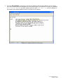
5. Type the AT+LCIFCG? command to check the IP address and the MAC address of the modem.
The “eth0” section shows the statistics for the Ethernet jack. For example, in Figure 4.8, HWaddr
00:11:DB:00:88:A6 is the MAC address and inet addr:192.168.1.50 is the IP address of
the modem (the default address used to connect to the modem).
Figure 4.8: Modem Ethernet information
001-0003-822 Rev 1
Page 17 of 48
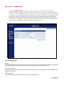
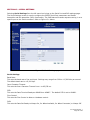
SECTION 5 – PROVISIONING
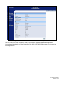
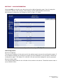
Selecting Provisioning from the left menu bar brings up the provisioning activation page. When a
new modem is powered up for the first time, most of the provisioning information is blank or has
information that needs to be changed. The device is usually shipped with the radio ready to be
provisioned on a cellular carrier’s network. Features called Over-The-Air Service Provisioning
(OTASP) and Internet Over-The-Air (IOTA) are supported, which allow the cellular providers to
program the modem with specific information to activate the account.
Figure 5.1: Provisioning page
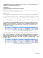
Provisioning Information: Current Status
ESN:
The Electronic Serial Number is only applicable for the CDMA product line, carrier specific (AllTel,
Verizon, Sprint, etc). This number is used to set up the user account with the cellular provider.
MDN/MTN:
This is the actual phone number of the device as supplied by the carrier. When the unit is
successfully provisioned, the phone number for the user account will be displayed.
MIN/IMSI:
This number is used by the Mobile Telephone Network and will be different if ported from another
carrier (not used by end user of the device).
001-0003-822 Rev 1
Page 18 of 48
PRL:
Preferred Roaming List, only applicable for the CDMA product line, carrier specific (AllTel, Verizon,
Sprint, etc).
SID:
System ID (Identity), provided by the Carrier.
NID:
Network Identifier, this is supplied automatically from the network.
Channel:
Cell Site channel number to which the modem is connected. This number can be useful to the
cellular provider for troubleshooting purposes.
Frequency:
Cellular frequency band the modem is using, 800MHz and 1900MHz are mainly in the US and
outlying areas. In some cases 900 and 1800 will be seen for European or Foreign carriers.
Roaming:
Options are either Roaming or Not Roaming and may defer from the PRL in the case of CDMA. For
provisioning, the unit must NOT be roaming.
Signal Strength (dBm):
Measured in dBm, this is the Received Signal Strength Indicator (RSSI). For provisioning, the signal
strength should be greater than -95 dBm.
Activation: Manual-Entry Activation
MDN:
The Mobile Directory Number assigned by the cellular provider for the specific ESN on the user
account.
MIN:
Mobile Identification Number, which only needs to be entered if different than the MDN.
Unlock Code:
A carrier supplied activation code (usually 6 or 7 digits for Sprint accounts).
Click the Write MDN/MSID button when the required information has been entered.
Activation: OTASP and IOTA
Command (OTASP Only):
This is the dial command used for provisioning the modem. For Verizon OTASP the number is
*22899. For IOTA this field should be left blank.
Click the OTASP or the IOTA button (depending on the carrier) to start the provisioning process.
Please refer Section 6 for information on provisioning the modem for various cellular providers.
001-0003-822 Rev 1
Page 19 of 48
SECTION 6 – CARRIER SPECIFIC PROVISIONING INFORMATION
Refer to Section 5 for more information about the Provisioning page.
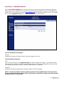
Verizon Wireless Subscribers
• Provisioning must occur in a non-roaming area of the Verizon network with a medium to
strong signal strength.
• Select “Provisioning” from the side menu bar.
• Confirm the OTASP command reads *22899.
• Click the “OTASP” button.
Figure 6.1: Verizon Provisioning Page
001-0003-822 Rev 1
Page 20 of 48
Sprint PCS Subscribers
• Provisioning must occur in a non-roaming area of the Sprint network with a medium to strong
signal strength.
• Select “Provisioning” from the side menu bar.
• Input the MDN, MIN, & Unlock Code from your provider
• Click the “Write MDN/MSID” button.
• Confirm the command for OTASP is blank.
• Click the “IOTA” button.
Figure 6.2: Sprint Provisioning Page
001-0003-822 Rev 1
Page 21 of 48
Alltel Subscribers
• Provisioning must occur in a non-roaming area of the Alltel network with a medium to strong
signal strength.
• Select “Provisioning” from the side menu bar.
• Confirm the command for OTASP is blank.
• Input the MDN and MIN from your provider
• Click the “Write MDN/MSID” button.
• Reset the unit from the Home page.
Figure 6.3: Alltel Provisioning Page
001-0003-822 Rev 1
Page 22 of 48
Telus (Canada) Subscribers
• Provisioning must occur in a non-roaming area of the Telus network with a medium to strong
signal strength.
• Select “Provisioning” from the side menu bar.
• Confirm the OTASP command reads *22803.
• Click the “OTASP” button.
Figure 6.4: Telus Provisioning Page
001-0003-822 Rev 1
Page 23 of 48
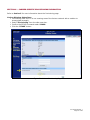
SECTION 7 – LAN CONFIGURATION
Selecting LAN from the left menu bar brings up the LAN configuration page. From this page the
modem’s IP address, DNC settings, DHCP settings, PPPoE enable/disable, and Remote
Administration parameters are configured. Refer to Figure 7.1 below.
Figure 7.1: LAN configuration page
LAN Configuration
Ethernet IP Address:
This sets the IP address of this device and is the address used to access the configuration pages. If
the IP address changes you will have to re-enter the new IP address in your browser to access the
configuration pages. The default IP is 192.168.1.50 and should be changed for security purposes.
Ethernet Subnet Mask:
This sets the subnet mask for the LAN side of the modem to the device. The default subnet mask is
set to 255.255.255.0.
001-0003-822 Rev 1
Page 24 of 48
DNS Resolving
DNS Auto:
Selecting Enable will automatically set DNS Server 1 to the Ethernet address set in the LAN
configuration section. Selecting Disable will allow different DNS server IP addresses to be set.
DNS Server 1 IP Address:
Ethernet IP address of the preferred DNS server.
DNS Server 2 IP Address:
Ethernet address of the alternate DNS server.
DHCP Configuration
DHCP:
Dynamic Host Configuration Protocol; a protocol used by client devices that are connected to the
LAN port of this device to automatically obtain an IP address assigned by this device. Selecting
Enable will configure this device to assign IP addresses to client devices taken from a pool specified
by the values entered in DHCP start range and DHCP end range. Selecting Disable will turn off the
DHCP server functionality.
DHCP start range:
DHCP server starting IP address. The default start range is set to 192.168.1.100.
DHCP end range:
DHCP server ending IP address. The default end range is set to 192.168.1.200. The largest settable
number is 253.
DHCP Lease Time:
Sets the duration, in seconds, the connected device is allowed to keep the assigned IP address. The
default lease time is set to 86400 seconds (24 hours). In many cases it is possible for the device to
receive the same IP address after the lease time expires.
PPPoE Setup
PPPoE:
Point To Point Protocol over Ethernet is used to establish internet connections using the Ethernet.
Selecting Enable will allow a PPP over Ethernet connection. Selecting Disable will shut off PPPoE
functionality. Click on the “Save” button to change the LAN settings.
Note that when PPPoE is enabled, the DHCP Server is automatically disabled. If the DHCP server is
enabled again after the PPPoE is disabled, the IP parameters will need to be re-entered.
After PPPoE has been enabled, a broadband connection can be created on the PC side. The following
steps show how to create a broadband network connection in Windows XP.
001-0003-822 Rev 1
Page 25 of 48
First, go to the Control Panel and select “Network Connections” to bring up the Network Connection
window (Figure 7.2).
Figure 7.2: Network Connection screen
Select “Create a new connection” in the Network Tasks menu. Follow the steps through the wizard
for creating a broadband internet connection.
001-0003-822 Rev 1
Page 26 of 48
Provide an ISP Name to identify this connection. If your carrier requires a username and password,
enter them here, otherwise leave these entries blank.
After finishing the wizard, a Broadband connection icon will appear on the Network Connections
window as shown in Figure 7.3.
Figure 7.3: Network Connection with Broadband icon
001-0003-822 Rev 1
Page 27 of 48
Double clicking on the broadband icon will bring up the connection screen shown below in Figure 7.4.
Figure 7.4: PPPoE Connect screen
If a Username and Password are required, input them in the provided fields. Select “Connect” to
initiate the login process to connect the modem to the carrier network using PPPoE.
001-0003-822 Rev 1
Page 28 of 48
To allow the PC LAN connection to access the modem’s web interface, the TCP/IP Properties will
need an IP address entered manually. This is because the DHCP server is disabled. Right click on
the Local LAN connection icon and select “Properties”. Refer to Figure 7.5 below.
Figure 7.5 TCP/IP Properties
If PPPoE is disabled and the DHCP server is re-established in the modem, remember to select
“Obtain an IP address automatically” at this screen. This will allow the modem to set the IP address
of the LAN connection.
Remote Administration
Remote Configure:
Selecting Enable will allow remote access to the modem’s configuration screens through the cellular
network connection. Selecting Disable will shut off the ability to remotely access the modem’s
configuration screens.
Incoming Port:
This sets the port number used to remotely configure the modem. The default port is set to 8080.
Admin Password:
This sets the password required for remote configuration accessibility.
Confirm Password:
Re-type the Admin Password to confirm the correct spelling.
001-0003-822 Rev 1
Page 29 of 48
SECTION 8 – PORT FORWARDING SETTINGS
Selecting Port Forwarding from the left menu bar brings up the Port Forwarding configuration
page. Port Forwarding is a technique for transmitting and receiving network traffic through a router
that involves re-writing the source and/or destination IP addresses and usually the TCP/UDP port
numbers of IP packets as they pass through. The various routing configurations will be displayed in
the IP mapping table at the bottom of the screen. Refer to Figure 8.1 below.
Figure 8.1: Port Forwarding configuration page
Port Forwarding Support
Port Forwarding Enable:
When set to Enable, will allow the modem to use the Port Forwarding routes described in the IP
mapping table. When set to Disable, will shut down the Port Forwarding functionality. The SAVE
button must be pressed for changes to take effect.
Port Forwarding Configuration
Mapping No:
This sets the Mapping Number for the IP mapping table at the bottom of the screen. The mapping
numbers must be listed in sequential numerical order starting with 1 (i.e. 1, 2, 3 …).
Protocol:
This sets the data protocol as either tcp, udp, or all.
001-0003-822 Rev 1
Page 30 of 48
Source IP Address:
This specifies an IP address that is allowed to access the modem or a wildcard IP address of 0.0.0.0
that allows all IP address to access the modem.
Incoming Port:
This sets the external port number for incoming requests.
Destination IP Address:
This sets the Local Area Network Address of the device connected to the modems Ethernet Jack.
Inbound requests will be forwarded to this IP address.
Destination Port:
This sets the Local Area Network port number used when forwarding to the destination IP address.
As an example, if it were required that all incoming addresses using port 81 and 8081 be routed to
IP address 192.168.1.222 on port 80 then the following information would be entered.
First, set the mapping number to 1, set the protocol to all, set the source IP address to 0.0.0.0 and
the incoming port to 81, set the destination IP address to 192.168.1.222 and the destination port to
80, then click the SAVE button. This will set the first entry in the table as Item 1.
To route port 8081 as well, enter a mapping number of 2, set the protocol to all, set the source IP
address to 0.0.0.0 and the incoming port to 8081, then set the destination IP address and port to
the same values as before and click the SAVE button. A second entry will be created as item 2,
shown in Figure 8.2 below.
Figure 8.2: Port Forwarding Mapping Table example 1
As a second example, add the requirement to forward information from IP address 192.168.2.100,
port 8083 to IP address 192.168.1.223, port 8083 using the tcp protocol.
Enter a mapping number of 3, set the protocol to tcp, set the source IP address to 192.168.2.100
and the incoming port to 8083, then set the destination IP address to 192.168.1.223 and the
destination port to 8083, then click the SAVE button. A third entry will be created as item 3, shown
in Figure 8.3 below.
Figure 8.3: Forwarding Mapping Table example 2
001-0003-822 Rev 1
Page 31 of 48
SECTION 9 – ROUTING
Selecting Routing from the left menu bar brings up the routing configuration page. The Routing
screen is used to enable or disable Routing Information Protocol (RIP) and Virtual Router
Redundancy Protocol (VRRP) routing. Static route tables are also created from the Routing screen
and appear at the bottom. Static Routing refers to a manual method used to set up routing between
networks.
Figure 9.1: Routing configuration page
RIP Routing
RIP Enable:
Selecting Enable will allow the RIP functionality. Selecting Disable will shut off RIP functionality. RIP
allows the router to dynamically adapt to changes in network connections by communicating
information about which networks each router can reach and how far away those networks are. The
SAVE button must be pressed for changes to take effect.
VRRP Configuration
VRRP Enable:
Selecting Enable will allow the VRRP functionality. Selecting Disable will shut off VRRP functionality.
VRRP specifies an election protocol that dynamically assigns responsibility for a virtual router to one
of the VRRP routers on a LAN. The SAVE button must be pressed for changes to take effect.
001-0003-822 Rev 1
Page 32 of 48
Virtual Device ID:
This sets the virtual device numeric identifier, ranging from 1 to 255.
Virtual IP Address:
This sets the Ethernet IP address of the virtual device.
Static Routes
Route No:
This sets the Static Route Table entry number value, ranging from 1 to 65,535. The Static Route
entries must start with 1 and be incremented by 1 for each additional entry.
Route Name:
This sets the alphanumeric identifier of the static route in the Static Route Table.
Destination IP Address:
This sets the IP address of the destination network.
IP Subnet Mask:
This sets the subnet mask of the destination network.
Gateway IP Address:
This sets the local network IP address for the gateway to the destination network.
Metric:
Number ranging from 1 to 65,535. The lower the metric value the higher the route priority.
The ADD button must be pressed to add the configured route to the Static Route Table.
As an example, if a router connected on the Ethernet side of the modem has a gateway IP address
of 192.168.1.2 and is interfaced to network 192.168.2.0 the following would be entered in the Static
Route Table to allow a device to get on the 192.168.2.0 network.
Set the Route Number to 1, name the Route (i.e. route1), set the destination IP Address to
192.168.2.0, set the IP Subnet Mask to 255.255.255.0, set the Gateway IP Address to 192.168.1.2,
and set the Metric to 1. The following entry will be made in the Static Route Table:
Figure 9.2: Static Route Table example
001-0003-822 Rev 1
Page 33 of 48
SECTION 10 – SIMPLE NETWORK MANAGEMENT PROTOCOL (SNMP)
Selecting SNMP from the left menu bar brings up the Simple Network Management Protocol
configuration page. SNMP is used in network management systems to monitor network-attached
devices for conditions that warrant administrative attention. SNMP version v1 is supported.
Figure 10.1: SNMP configuration page
SNMP Configuration
SNMP:
Selecting Enable will allow the SNMP functionality. Selecting Disable will shut off SNMP functionality.
Read-only Community Name:
The community string used for accessing the read-only Management Information Bases (MIBs).
Read-write Community Name:
The community string used for accessing all Management Information Bases (MIBs) including
writable MIBs.
001-0003-822 Rev 1
Page 34 of 48
SECTION 11 – DYNAMIC DNS
Selecting Dynamic DNS from the left menu bar brings up the Simple Dynamic DNS
configuration page. Dynamic DNS is a system which allows the domain name data held in a
name server to be updated in real time. This allows an Internet domain name to be assigned
to a device with a varying (dynamic) IP address. This makes it possible for other sites on the
Internet to establish connections to the machine without needing to track the IP address
themselves. A number of third party providers offer Dynamic DNS services ("DDNS") free or
for a charge. For example, a free service provided by “No-IP" allows users to setup between
one and five host names on a domain name provided by No-IP.
Figure 11.1: Dynamic DNS configuration page
NO-IP Configuration
NO-IP:
Selecting Enable will allow the modem to provide the NO-IP service dynamic IP address information.
Selecting Disable will stop any IP information from being sent to the NO-IP service.
User at NO-IP.com:
The username used when setting up the NO-IP.com account. This username is used to login to the
NO-IP.com service.
NOIP Password:
The password associated with the NO-IP.com username account.
001-0003-822 Rev 1
Page 35 of 48
Hostname:
The hostname identified to the NO-IP.com service, for example http://test.myserver.com. This
hostname is used to access the web information at the associated carrier IP address.
Update Interval:
Sets the interval, in minutes (0 to 65,535), the modem will update the NO-IP server of its carrier
assigned IP address. It is recommended to set this interval as long as necessary. Each update is
considered a data call by the cellular provider and could deplete low usage data plan minutes.
A No-IP service account can be set up at www.no-ip.com. There are several managed DNS service
account packages available as.
001-0003-822 Rev 1
Page 36 of 48
SECTION 12 – FIRMWARE UPDATE
Selecting Firmware Update from the left menu bar brings up the firmware status and upgrade
page. When newer versions of the modem firmware become available, the user can download the
proper file from the CalAmp web site (www.calamp.com) and manually update the unit. The update
file is named upgrade.tar.gz and is specific to each unit’s model number.
Figure 12.1: Firmware Update page
Current Firmware Information
Version:
Displays the modem firmware version currently loaded in the unit.
Download New Firmware
File:
This is the input field for the upgrade.tar.gz file used to update the modem. The Browse button
can be used to locate the file from a specific folder after it has been downloaded from the web site.
The update can be done remotely if Remote Administration is enabled.
Progress:
Displays the update progress after the Save button has been pressed.
NOTE: All user parameter values previously setup for the modem will be lost and set to
factory default parameter values when the firmware is updated. Please record all modem
parameters prior to an update.
001-0003-822 Rev 1
Page 37 of 48
SECTION 13 – SERIAL SETTINGS
Selecting Serial Settings from the left menu bar brings up the Serial Port and PAD settings page.
The Serial Settings screen is used to configure the RS232 Serial Port parameters and Packet
Assembler and Dis-assembler (PAD) functionality. The PAD feature forwards requests coming in on a
specific port to the Serial connector. Refer to Figure 13.1 below.
Figure 13.1 Serial Settings page
Serial Settings
Baud Rate:
This sets the baud rate of the serial port. Settings may range from 300 to 115,200 bits per second.
The default baud rate is 115,200 bps.
Inter Character Timeout:
This sets the Inter Character Timeout from 1 to 65,535 ms.
DTR:
This sets the Data Terminal Ready as AD&D0 thru AD&D7. The default DTR is set to AD&D0.
Flow Control:
This sets the Flow Control to None or Hardware control.
DSR:
This sets the Data Set Ready to Always On, On When Available, On When Connected, or Always Off.
001-0003-822 Rev 1
Page 38 of 48
DCD:
This sets the Data Carrier Detect to Always On, Connect On, or Always Off.
RI:
This sets the Ring Indicator to Always On, Incoming Ring, or Always Off.
Periodic Reset Timeout:
This sets the Periodic Reset Timeout from 0 to 65,535 ms.
Id:
This sets an alphanumerical Identifier for the serial connection.
PAD Settings
Incoming Friendly IP Address:
This sets the IP address of the device using the PAD functionality.
Port:
This sets the port number used for forwarding requests to the serial port.
Local Encoding:
Select buttons to Enable or Disable local encoding of the data packet.
PAD Mode:
Select buttons to set the PAD mode of the modem as a Server or Client. Server mode is commonly
selected when the modem is providing the interface via the RS232 port.
Pad Protocol:
This sets the data protocol for the PAD to tcp or udp data.
001-0003-822 Rev 1
Page 39 of 48
SECTION 14 – SERIAL INTERFACE COMMUNICATION
Many of the modem features available using the web interface can also be accessed via the RS232
serial interface. Table 14.1 lists the various serial AT commands that can be used to configure and
operate the modem via the serial port.
Table 14.1: Serial AT Commands
Command
Description
=1 Configures the serial Terminal Emulator to direct recognized AT commands
to the cell module, as opposed to the modem-emulator of the unit. Note:
The Default Value of this setting is AT+LCPAST=0
AT+LCPAST
=2 Configures the serial Terminal Emulator to direct all AT commands to the cell
module, as opposed to the modem emulator of the unit. Note: This mode
can only be exited by power-cycling the modem.
Dialing Related Commands
Active Connection:
? Displays current active profile connection.
=0 Terminates the connection and prevents further attempts during the current
AT+LCGASC
session.
=1 This command tells the modem to dial out using the settings of profile 1. It
will automatically redial if the connection is dropped.
Displays “eth0” and “ppp0” connection information. “eth0” are the statistics for
the Ethernet jack and “ppp0” are statistics for the modems PPP connection via
AT+LCIFCG?
the antenna IP. If you do not see the “ppp0” section you are not actively
connected.
Periodic Reset Timeout
? Displays current timer setting.
AT+LCPRT
=0 Disables timer (default).
=n Sets the modem to reboot once every n minutes.
Serial Commands
Dialing Profile:
? Displays the current profile settings.
=<ProfileNumber>,<Number>,<UserName>,<Password>,<Transport>,<Mode>,
<IPAddress>,<Port>
AT+LCPRFL
AT+LCICTO
<ProfileNumber> Usually 1
<Number> Phone number to dial. Defualt is ATD#777
<UserName> User Name if required to login to 1xRTT. Do not leave blank, use
a single space if no username,
<Password> Password if required to login to 1xRTT Do not leave blank, use a
single space if no password.
<Transport> 0 = TCP, 1 = UDP
<Mode> 0 :Modem acts as client, 1 :Modem acts as server.
<Local Encoding> Always set to 0
<IP Address> The IP To Connect To When Acting As A Client , or the Trusted
Incoming IP To Listen To When Acting As Server. A wildcard value of 0.0.0.0
will allow any incoming IP address access.
<Port> Port To Connect To When Acting As A Client. Trusted Incoming Port To
Listen To When Acting As A Server. Traffic on this port is forwarded to the
DE-9 serial connector of the modem and converted to ASCII by stripping off
the TCP/IP Headers and adding TCP headers to outgoing ASCII strings. This
is called PAD (“Packet Assembler/Dissassembler”).
Sets the inter-character timer. Default is 50 ms.
001-0003-822 Rev 1
Page 40 of 48
Serial Port Configuration Commands
Serial Port baud rate:
AT+IPR
? Displays current baud rate
=n Sets the baud rate to value of n. Default value is 115200.
Hardware Flow Control:
? Displays current setting
AT+IFC
=0,0 No Flow Control
=1,1 Xon/Xoff
=2,2 Hardware
DTR Configuration:
This parameter determines how the modem responds when the Data Terminal
Ready circuit changes state. Default value AT&D0.
AT&Dn
AT&Rn
AT&D0 Ignore DTR.
AT&D1 If in the Online Data State, upon an on-to-off transition of DTR, the
modem enters Online Command State and issues an OK result code; the call
remains connected. Otherwise, ignore DTR.
AT&D2 If in the Online Data State or Online Command State upon an on-to-off
transition of DTR, the modem performs an orderly clear-down of the call and
returns to the command state. Automatic answer is disabled while DTR
remains off.
AT&D4 The modem auto-dials the default remote station (as determined by
AT+LCPRFL) upon an off-to-on transition of DTR and enters the Online Data
State. The modem ends the call and enters the command state upon an onto-off transition of DTR.
AT&D5 The modem auto-dials the default remote station (as determined by
AT+LCPRFL) upon an on-to-off transition of DTR and enters the Online Data
State. The modem ends the call and enters the command state upon an offto-on transition of DTR.
AT&D6 Upon an on-to-off transition of DTR, the modem performs an orderly
clear-down of any session and turns OFF the RF module. Upon an off-to-on
transition of DTR, the modem turns ON the RF module and reestablishes the
radio session as determined by the AT+LCGASC setting.
AT&D7 Upon an on-to-off transition of DTR, the modem performs an orderly
clear-down of any session and turns OFF the RF module. Upon an off-to-on
transition of DTR, the modem turns ON the RF module and reestablishes the
radio session.
AT&D8 Upon an on-to-off transition of DTR, the modem performs an orderly
clear-down of any session and turns OFF the RF module. Upon an off-to-on
transition of DTR, the modem turns ON the RF module and reestablishes the
radio session and auto-dials the default remote station (as determined by
AT+LCPRFL)
RTS Configuration:
This parameter determines how the modem responds when the Request To
Send circuit changes state. The state of this parameter may be affected by the
state of the +IFC parameter and vise versa, the last issued command takes
precedence. Default value AT&R0
AT&R0 Ignore RTS.
AT&R2 RTS Flow Control, if RTS is off the terminal will not send data to the
host.
001-0003-822 Rev 1
Page 41 of 48
DSR Configuration:
This parameter determines how the modem controls the state of the Data Set
Ready circuit. Default value AT&S0.
AT&Sn
AT&Qn
AT&Cn
AT&Nn
AT&S0 DSR always ON.
AT&S1 DSR ON when the RF signal present and phone registered on network.
AT&S2 DSR ON when connected to CDMA.
AT&S3 DSR always OFF.
AT&S4 DSR controlled via I/O control feature.
CTS Configuration:
This parameter determines how the modem controls the state of the Clear to
Send circuit. Default value AT&Q0.
AT&Q0 CTS always ON.
AT&Q1 CTS always OFF.
AT&Q2 CTS flow control, terminal sets CTS low if it is unable to accept data
from host.
AT&Q3 CTS follows state of RTS.
AT&Q4 DSR Controlled via I/O control feature.
DCD Configuration:
This parameter determines how the modem controls the state of the Carrier
Detect circuit. Default value AT&C1.
AT&C0 DCD always ON.
AT&C1 DCD ON when connected to remote host.
AT&C2 DCD always OFF.
AT&C3 DSR controlled via I/O control feature.
RI Configuration:
This parameter determines how the modem controls the state of the Ring
Indicator circuit. Default value AT&N1.
AT&N0 RI always ON.
AT&N1 RI tracks incoming ring pulse.
AT&N2 RI always OFF.
AT&N3 RI controlled via I/O control feature.
AT&N4 RI acts as watchdog output (changes state once per second under
normal conditions).
001-0003-822 Rev 1
Page 42 of 48
Ethernet Related Commands
Modem’s IP Address:
AT+LCETHI
? Displays current IP address.
=x.x.x.x Sets the modem’s IP address (default: 192.168.1.50).
Modem’s Subnetmask:
AT+LCETHN
? Displays current subnetmask.
=x.x.x.x Sets the modem’s subnetmask (default: 255.255.255.0).
DHCP Server Settings:
? Displays the current settings.
AT+LCDHCP
=0 Turns off the DHCP server.
=<DHCPStartAddress>,<DHCPEndAddress>,<LeaseTime>,<DNS1>,<DNS2>
AT+LCMAPP
Port Forwarding Settings:
? Displays the current settings.
=<Profile>,<Protocol>,<ExternalIPAddr>,<ExternalPort>,<InternalIPAddr>,<LocalPort>
AT+LCPPPOE
PPPoE Connection:
? Displays the current settings.
=0 Disable PPPoE
=1 Enable PPPoE
001-0003-822 Rev 1
Page 43 of 48
SECTION 15 – SPECIFICATIONS
Product specifications are subject to change without notice.
General Specifications
Interface Connectors:
RS-232 DE-9S Connector (DCE)
10/100 Base-T Full Duplex
USB Host Controller
Power Connector:
2.1mm/5.5mm DC Barrel Jack (Center Positive)
LED Indicators:
SVC-TYPE, TX/RX, DCD, RSSI
Antenna Interface:
SMA female
Size:
5.60 x 3.11 x 1.71 in.
Weight:
10.0 oz.
Power Input:
9.0 – 28VDC 1.7 W; 140 mA @ 12 VDC (average idle)
9.0 – 28VDC 3.8 W; 320 mA @ 12 VDC (peak active 822-1XRT)
9.0 – 28VDC 6.5 W; 550 mA @ 12 VDC (peak active 882-EVDO)
Maximum TX Power:
CDMA: +23.5 dBm min. / +22.5 dBm min (1900MHz)
Rx Sensitivity:
CDMA: >-104 dBm
Frequencies:
Cellular:
PCS:
Temperature:
Operating: -30°C to +60°C (-22° to 140°F) 100% Duty Cycle
Storage: -55°C to +85°C (-67° to 185°F)
Emissions:
FCC Part 15B
Transport Protocols:
UDP/TCP
Command Protocol:
Web interface, Command line v.250 AT, & proprietary
TX: 824-849 MHz Rx: 869-894 MHz
TX: 1850-1910 MHz Rx: 1930-1990 MHz
Certifications:
822-1XRT
CDG 2, Tested and approved
FCC ID: RD5-LCC0308
Industry Canada ID: IC: 418A-LCC0308
882-EVDO
CDG 2, Carrier approvals pending
FCC ID: N7N-MC5725
Industry Canada ID: IC: 2417C-MC5725
NOTE: Power consumption while transmitting is dependant on the TX power level of the cellular
module. The TX power level of the module is controlled by the cellular base station.
001-0003-822 Rev 1
Page 44 of 48
Mechanical Specifications
The following section describes in detail the exterior dimensions of the 822-1XRT/882-EVDO modem
and how to utilize the mounting flanges to secure the modem to any surface, which can be drilled for
such a purpose. The drawings may be used as layout reference, but it is advised that a physical
comparison be made to the modem before proceeding with the mounting process.
All dimensions in inches.
001-0003-822 Rev 1
Page 45 of 48
SECTION 16 – ABBREVIATIONS
Abbreviation
Description
CDMA
Code Division Multiple Access
CTS
Clear to Send
DCD
Data Carrier Detect
ESN
Electronic Serial Number
EVDO
Evolution Data Optimized
GPRS
General Packet Radio Service
GPS
Global Positioning System
IOTA
Internet Over the Air
LED
Light Emitting Diode
OTA
Over the Air
OTASP
Over the Air Service Provisioning
PPP
Point to Point Protocol
PRL
Preferred Roaming List
RSSI
Receive Signal Strength Indication
Rx
Receive
Tx
Transmit
001-0003-822 Rev 1
Page 46 of 48
SECTION 17 – SERVICE AND SUPPORT
Product Warranty, RMA and Contact Information
CalAmp guarantees that every 822-1XRT/882-EVDO Cellular Modem will be free from physical
defects in material and workmanship for one (1) year from the date of purchase when used
within the limits set forth in the Specifications section of this manual.
The manufacturer's warranty statement is available in Appendix 1. If the product proves
defective during the warranty period, contact CalAmp DataCom Customer Service to obtain a
Return Material Authorization (RMA).
RMA Request
Contact Customer Service:
Dataradio dba CalAmp Wireless DataCom
299 Johnson Avenue, Suite 110
Waseca, MN 56093
Tel: 507-833-8819 ext. 6707
Fax: 507-833-6748
BE SURE TO HAVE THE EQUIPMENT MODEL AND SERIAL NUMBER, AND BILLING AND
SHIPPING ADDRESSES ON HAND WHEN CALLING.
When returning a product, mark the RMA clearly on the outside of the package. Include a
complete description of the problem and the name and telephone number of a contact
person. RETURN REQUESTS WILL NOT BE PROCESSED WITHOUT THIS INFORMATION.
For units in warranty, customers are responsible for shipping charges to CalAmp Wireless
DataCom. For units returned out of warranty, customers are responsible for all shipping
charges. Return shipping instructions are the responsibility of the customer.
Product Documentation
CalAmp reserves the right to update its products, software, or documentation without
obligation to notify any individual or entity. Product updates may result in differences
between the information provided in this manual and the product shipped. For the most
current product documentation, visit www.calamp.com for datasheets, programming software
and user manuals.
Technical Support
M-F 7:30 AM to 4:30 PM CDT
CalAmp Wireless DataCom
299 Johnson Avenue, Suite 110
Waseca, MN 56093
Tel: 507-833-8819
E-mail: [email protected]
001-0003-822 Rev 1
Page 47 of 48
APPENDIX 1 – WARRANTY STATEMENT
CalAmp DataCom warrants to the original purchaser for use ("Buyer") that data telemetry products
manufactured by DRL ("Products") are free from defects in material and workmanship and will
conform to DRL's published technical specifications for a period of, except as noted below, one (1)
year from the date of shipment to Buyer. DRL makes no warranty with respect to any equipment not
manufactured by DRL, and any such equipment shall carry the original equipment manufacturer's
warranty only. DRL further makes no warranty as to and specifically disclaims liability for,
availability, range, coverage, grade of service or operation of the repeater system provided by the
carrier or repeater operator. Any return shipping charges for third party equipment to their
respective repair facilities are chargeable and will be passed on to the Buyer.
If any Product fails to meet the warranty set forth above during the applicable warranty period and
is returned to a location designated by DRL. DRL, at its option, shall either repair or replace such
defective Product, directly or through an authorized service agent, within thirty (30) days of receipt
of same. No Products may be returned without prior authorization from DRL. Any repaired or
replaced Products shall be warranted for the remainder of the original warranty period. Buyer shall
pay all shipping charges, handling charges, fees and duties for returning defective Products to DRL
or DRL's authorized service agent. DRL will pay the return shipping charges if the Product is repaired
or replaced under warranty, exclusive of fees and duties. Repair or replacement of defective
Products as set forth in this paragraph fulfills any and all warranty obligations on the part of DRL.
This warranty is void and DRL shall not be obligated to replace or repair any Products if (i) the
Product has been used in other than its normal and customary manner; (ii) the Product has been
subject to misuse, accident, neglect or damage or has been used other than with DRL approved
accessories and equipment; (iii) unauthorized alteration or repairs have been made or unapproved
parts have been used in or with the Product; or (iv) Buyer failed to notify DRL or DRL's authorized
service agent of the defect during the applicable warranty period. DRL is the final arbiter of such
claims.
THE AFORESAID WARRANTIES ARE IN LIEU OF ALL OTHER WARRANTIES, EXPRESSED AND
IMPLIED, INCLUDING BUT NOT LIMITED TO, ANY IMPLIED WARRANTY OF MERCHANTABILITY OR
FITNESS FOR A PARTICULAR PURPOSE. DRL AND BUYER AGREE THAT BUYER'S EXCLUSIVE REMEDY
FOR ANY BREACH OF ANY OF SAID WARRANTIES IT AS SET FORTH ABOVE. BUYER AGREES THAT IN
NO EVENT SHALL DRL BE LIABLE FOR INCIDENTAL, CONSEQUENTIAL, SPECIAL, INDIRECT OR
EXEMPLARY DAMAGES WHETHER ON THE BASIS OF NEGLIGENCE, STRICT LIABILITY OR
OTHERWISE. The purpose of the exclusive remedies set forth above shall be to provide Buyer with
repair or replacement of non-complying Products in the manner provided above. These exclusive
remedies shall not be deemed to have failed of their essential purpose so long as DRL is willing and
able to repair or replace non-complying Products in the manner set forth above.
This warranty applies to all Products sold worldwide. Some states do not allow limitations on implied
warranties so the above limitations may not be applicable. You may also have other rights, which
vary from state to state.
EXCEPTIONS
ONE YEAR:
Labor to replace defective parts in repeaters or base stations
THIRTY DAY:
Tuning and adjustment of telemetry radios
NO WARRANTY: Fuses, lamps and other expendable parts
Effective 1/2008
001-0003-822 Rev 1
Page 48 of 48