1
Summit WM Getting Started Guide
Extreme Networks, Inc.
3585 Monroe Street
Santa Clara, California 95051
(888) 257-3000
(408) 579-2800
http://www.extremenetworks.com
Published: March 2007
Part number: 120385-00 Rev 01
[copyright ©] Alpine, Alpine 3804, Alpine 3802, Altitude, BlackDiamond, BlackDiamond 6808, BlackDiamond 6816,
EPICenter, Ethernet Everywhere, Extreme Ethernet Everywhere, Extreme Networks, Extreme Turbodrive, Extreme Velocity,
ExtremeWare, ExtremeWorks, ExtremeXOS, GlobalPx Content Director, the Go Purple Extreme Solution Partners Logo,
Sentriant, ServiceWatch, Summit, Summit24, Summit48, Summit1i, Summit4, Summit5i, Summit7i, Summit 48i, SummitRPS,
SummitGbX, Triumph, vMAN, the Extreme Networks logo, the Alpine logo, the BlackDiamond logo, the Summit logos, the
Extreme Turbodrive logo, and the Color Purple, among others, are trademarks or registered trademarks of Extreme Networks,
Inc. or its subsidiaries in the United States and other countries. Other names and marks may be the property of their respective
owners.
© 2007 Extreme Networks, Inc. All Rights Reserved.
Specifications are subject to change without notice.
Merit is a registered trademark of Merit Network, Inc. Solaris and Java are trademarks of Sun Microsystems, Inc. in the U.S.
and other countries. Avaya is a trademark of Avaya, Inc.
All other registered trademarks, trademarks and service marks are property of their respective owners.
The ExtremeXOS operating system is based, in part, on the Linux operating system. The machine-readable copy of the
corresponding source code is available for the cost of distribution. Please direct requests to Extreme Networks for more
information at the following address:
Legal Department
3585 Monroe Street
Santa Clara CA 95051
Summit WM Getting Started Guide
bkTOC.fm
For internal use only
Contents
Contents
0
1 About this guide . . . . . . . . . . . . . . . . . . . . . . . . . . . . . . . . . . . . . . . . . . . . . . . . . . . . . . . . . . . . . . . . . . . . . . .
1.1 Who should use this guide . . . . . . . . . . . . . . . . . . . . . . . . . . . . . . . . . . . . . . . . . . . . . . . . . . . . . . . . . . . . . . .
1.2 What is in this guide . . . . . . . . . . . . . . . . . . . . . . . . . . . . . . . . . . . . . . . . . . . . . . . . . . . . . . . . . . . . . . . . . . . .
1.3 Formatting conventions . . . . . . . . . . . . . . . . . . . . . . . . . . . . . . . . . . . . . . . . . . . . . . . . . . . . . . . . . . . . . . . . .
1.4 Document feedback . . . . . . . . . . . . . . . . . . . . . . . . . . . . . . . . . . . . . . . . . . . . . . . . . . . . . . . . . . . . . . . . . . . .
7
7
7
8
9
2 Summit WM-Series WLAN Switch Software Solution . . . . . . . . . . . . . . . . . . . . . . . . . . . . . . . . . . . . . . . .
2.1 Conceptual model . . . . . . . . . . . . . . . . . . . . . . . . . . . . . . . . . . . . . . . . . . . . . . . . . . . . . . . . . . . . . . . . . . . .
2.1.1 Summit WM Switch. . . . . . . . . . . . . . . . . . . . . . . . . . . . . . . . . . . . . . . . . . . . . . . . . . . . . . . . . . . . . . . .
2.1.1.1 Web-based centralized management of Altitude APs . . . . . . . . . . . . . . . . . . . . . . . . . . . . . . . . . .
2.1.1.2 Virtualized user segmentation . . . . . . . . . . . . . . . . . . . . . . . . . . . . . . . . . . . . . . . . . . . . . . . . . . . .
2.1.1.3 Summit Switch WM100: 32 WM-ADsAuthentication and encryption. . . . . . . . . . . . . . . . . . . . . . .
2.1.1.4 Intrusion detection . . . . . . . . . . . . . . . . . . . . . . . . . . . . . . . . . . . . . . . . . . . . . . . . . . . . . . . . . . . . .
2.1.1.5 Automatic assignment of IP addresses to the client devices. . . . . . . . . . . . . . . . . . . . . . . . . . . . .
2.1.1.6 Web authentication . . . . . . . . . . . . . . . . . . . . . . . . . . . . . . . . . . . . . . . . . . . . . . . . . . . . . . . . . . . .
2.1.2 Altitude AP . . . . . . . . . . . . . . . . . . . . . . . . . . . . . . . . . . . . . . . . . . . . . . . . . . . . . . . . . . . . . . . . . . . . . .
2.1.3 Summit WM-Series WLAN Solution topology and network elements. . . . . . . . . . . . . . . . . . . . . . . . . .
2.1.4 Discovery mechanism in Summit WM-Series WLAN Solution . . . . . . . . . . . . . . . . . . . . . . . . . . . . . . .
2.1.4.1 Discovery mechanism between Altitude AP and Summit WM Switch. . . . . . . . . . . . . . . . . . . . . .
2.1.4.2 Discovery mechanism between mobility manager and mobility agents . . . . . . . . . . . . . . . . . . . .
2.1.5 DHCP usage scenarios in Summit WM-Series WLAN Solution . . . . . . . . . . . . . . . . . . . . . . . . . . . . . .
2.1.5.1 DHCP for Altitude APs. . . . . . . . . . . . . . . . . . . . . . . . . . . . . . . . . . . . . . . . . . . . . . . . . . . . . . . . . .
2.1.5.2 DHCP for WM-AD . . . . . . . . . . . . . . . . . . . . . . . . . . . . . . . . . . . . . . . . . . . . . . . . . . . . . . . . . . . . .
2.1.5.3 DHCP relay for WM-AD. . . . . . . . . . . . . . . . . . . . . . . . . . . . . . . . . . . . . . . . . . . . . . . . . . . . . . . . .
2.1.5.4 DHCP for traffic bridged locally at Altitude AP. . . . . . . . . . . . . . . . . . . . . . . . . . . . . . . . . . . . . . . .
2.2 Summit WM Switch’s physical description . . . . . . . . . . . . . . . . . . . . . . . . . . . . . . . . . . . . . . . . . . . . . . . . . .
2.2.1 Summit Switch WM2000 front panel. . . . . . . . . . . . . . . . . . . . . . . . . . . . . . . . . . . . . . . . . . . . . . . . . . .
2.2.1.1 LED states and Seven Segment Display (SSD) codes . . . . . . . . . . . . . . . . . . . . . . . . . . . . . . . . .
2.2.2 Summit Switch WM2000 back panel . . . . . . . . . . . . . . . . . . . . . . . . . . . . . . . . . . . . . . . . . . . . . . . . . .
2.2.3 Summit Switch WM1000 front panel. . . . . . . . . . . . . . . . . . . . . . . . . . . . . . . . . . . . . . . . . . . . . . . . . . .
2.2.4 Summit Switch WM1000 back panel . . . . . . . . . . . . . . . . . . . . . . . . . . . . . . . . . . . . . . . . . . . . . . . . . .
2.2.5 Summit Switch WM100 front panel. . . . . . . . . . . . . . . . . . . . . . . . . . . . . . . . . . . . . . . . . . . . . . . . . . . .
2.2.6 Summit Switch WM100 back panel . . . . . . . . . . . . . . . . . . . . . . . . . . . . . . . . . . . . . . . . . . . . . . . . . . .
2.3 Collecting information for installation . . . . . . . . . . . . . . . . . . . . . . . . . . . . . . . . . . . . . . . . . . . . . . . . . . . . . .
11
11
11
12
12
12
13
13
13
13
13
15
15
16
16
17
18
19
20
20
20
22
24
24
25
26
27
28
3 Summit WM-Series WLAN Switch configuration . . . . . . . . . . . . . . . . . . . . . . . . . . . . . . . . . . . . . . . . . . . .
3.1 Accessing the Summit WM-Series WLAN Switch for the first time . . . . . . . . . . . . . . . . . . . . . . . . . . . . . . .
3.2 Connecting the Summit WM Switch to the enterprise network . . . . . . . . . . . . . . . . . . . . . . . . . . . . . . . . . .
3.3 Changing the administrator password . . . . . . . . . . . . . . . . . . . . . . . . . . . . . . . . . . . . . . . . . . . . . . . . . . . . .
3.4 Configuring the network time . . . . . . . . . . . . . . . . . . . . . . . . . . . . . . . . . . . . . . . . . . . . . . . . . . . . . . . . . . . .
3.4.1 Configuring the network time using the system’s time . . . . . . . . . . . . . . . . . . . . . . . . . . . . . . . . . . . . .
3.4.2 Configuring the network time using the NTP . . . . . . . . . . . . . . . . . . . . . . . . . . . . . . . . . . . . . . . . . . . .
3.5 Generating a software license key . . . . . . . . . . . . . . . . . . . . . . . . . . . . . . . . . . . . . . . . . . . . . . . . . . . . . . . .
3.5.1 Retrieving a lost license key . . . . . . . . . . . . . . . . . . . . . . . . . . . . . . . . . . . . . . . . . . . . . . . . . . . . . . . . .
3.6 Applying a license key . . . . . . . . . . . . . . . . . . . . . . . . . . . . . . . . . . . . . . . . . . . . . . . . . . . . . . . . . . . . . . . . .
35
35
40
40
41
41
43
43
47
47
4 Physical ports configuration . . . . . . . . . . . . . . . . . . . . . . . . . . . . . . . . . . . . . . . . . . . . . . . . . . . . . . . . . . . . 49
4.1 Physical data ports overview . . . . . . . . . . . . . . . . . . . . . . . . . . . . . . . . . . . . . . . . . . . . . . . . . . . . . . . . . . . . 49
120385-00 Rev 01, March 2007
Summit WM, Getting Started Guide
3
bkTOC.fm
Contents
For internal use only
4.2 Configuring data ports . . . . . . . . . . . . . . . . . . . . . . . . . . . . . . . . . . . . . . . . . . . . . . . . . . . . . . . . . . . . . . . . 50
5 Routing configuration . . . . . . . . . . . . . . . . . . . . . . . . . . . . . . . . . . . . . . . . . . . . . . . . . . . . . . . . . . . . . . . . . . 53
5.1 Configuring static routing . . . . . . . . . . . . . . . . . . . . . . . . . . . . . . . . . . . . . . . . . . . . . . . . . . . . . . . . . . . . . . 53
5.1.1 Viewing the forwarding table . . . . . . . . . . . . . . . . . . . . . . . . . . . . . . . . . . . . . . . . . . . . . . . . . . . . . . . . 54
5.2 Configuring the OSPF routing. . . . . . . . . . . . . . . . . . . . . . . . . . . . . . . . . . . . . . . . . . . . . . . . . . . . . . . . . . . 55
5.2.1 Enabling OSPF globally on the Summit WM Switch . . . . . . . . . . . . . . . . . . . . . . . . . . . . . . . . . . . . . . 56
5.2.2 Defining the global OSPF parameters. . . . . . . . . . . . . . . . . . . . . . . . . . . . . . . . . . . . . . . . . . . . . . . . . 57
5.2.2.1 Confirming the ports are set for OSPF. . . . . . . . . . . . . . . . . . . . . . . . . . . . . . . . . . . . . . . . . . . . . 58
6 Configuring DHCP, DNS and IAS services . . . . . . . . . . . . . . . . . . . . . . . . . . . . . . . . . . . . . . . . . . . . . . . . . 61
6.1 DHCP service configuration . . . . . . . . . . . . . . . . . . . . . . . . . . . . . . . . . . . . . . . . . . . . . . . . . . . . . . . . . . . . 61
6.1.1 Configuring DHCP in Windows 2003 Server . . . . . . . . . . . . . . . . . . . . . . . . . . . . . . . . . . . . . . . . . . . . 61
6.1.2 Configuring DHCP in Red Hat Linux Server . . . . . . . . . . . . . . . . . . . . . . . . . . . . . . . . . . . . . . . . . . . . 65
6.2 IAS service configuration . . . . . . . . . . . . . . . . . . . . . . . . . . . . . . . . . . . . . . . . . . . . . . . . . . . . . . . . . . . . . . 67
6.2.1 Installing IAS on Windows 2003 Server . . . . . . . . . . . . . . . . . . . . . . . . . . . . . . . . . . . . . . . . . . . . . . . 68
6.2.2 Enabling IAS to authenticate users in active directory . . . . . . . . . . . . . . . . . . . . . . . . . . . . . . . . . . . . 68
6.2.3 Configuring IAS properties . . . . . . . . . . . . . . . . . . . . . . . . . . . . . . . . . . . . . . . . . . . . . . . . . . . . . . . . . 68
6.2.4 Configuring Summit WM Switch as IAS client . . . . . . . . . . . . . . . . . . . . . . . . . . . . . . . . . . . . . . . . . . . 71
6.2.5 Configuring Remote Access Policies. . . . . . . . . . . . . . . . . . . . . . . . . . . . . . . . . . . . . . . . . . . . . . . . . . 72
6.3 DNS service configuration . . . . . . . . . . . . . . . . . . . . . . . . . . . . . . . . . . . . . . . . . . . . . . . . . . . . . . . . . . . . . 76
6.3.1 Configuring DNS for internet access . . . . . . . . . . . . . . . . . . . . . . . . . . . . . . . . . . . . . . . . . . . . . . . . . . 77
6.3.2 Configuring DNS for Altitude APs discovery . . . . . . . . . . . . . . . . . . . . . . . . . . . . . . . . . . . . . . . . . . . . 78
7 Altitude AP’s configuration . . . . . . . . . . . . . . . . . . . . . . . . . . . . . . . . . . . . . . . . . . . . . . . . . . . . . . . . . . . . . 81
7.1 Altitude AP overview . . . . . . . . . . . . . . . . . . . . . . . . . . . . . . . . . . . . . . . . . . . . . . . . . . . . . . . . . . . . . . . . . . 81
7.2 Configuring the Altitude APs for the first time . . . . . . . . . . . . . . . . . . . . . . . . . . . . . . . . . . . . . . . . . . . . . . . 82
7.2.1 Manually approving pending Altitude APs . . . . . . . . . . . . . . . . . . . . . . . . . . . . . . . . . . . . . . . . . . . . . . 84
7.3 Assigning names to Altitude APs . . . . . . . . . . . . . . . . . . . . . . . . . . . . . . . . . . . . . . . . . . . . . . . . . . . . . . . . 85
7.4 Modifying Altitude APs’ properties . . . . . . . . . . . . . . . . . . . . . . . . . . . . . . . . . . . . . . . . . . . . . . . . . . . . . . . 85
7.5 Configuring static IP address for Altitude APs . . . . . . . . . . . . . . . . . . . . . . . . . . . . . . . . . . . . . . . . . . . . . . 86
7.6 Configuring VLAN tags for Altitude APs . . . . . . . . . . . . . . . . . . . . . . . . . . . . . . . . . . . . . . . . . . . . . . . . . . . 91
7.6.1 Resetting the Altitude AP to its factory default settings . . . . . . . . . . . . . . . . . . . . . . . . . . . . . . . . . . . . 92
7.7 Altitude AP’s LED states . . . . . . . . . . . . . . . . . . . . . . . . . . . . . . . . . . . . . . . . . . . . . . . . . . . . . . . . . . . . . . . 93
8 WM-AD configuration . . . . . . . . . . . . . . . . . . . . . . . . . . . . . . . . . . . . . . . . . . . . . . . . . . . . . . . . . . . . . . . . . . 95
8.1 WM-AD topology overview . . . . . . . . . . . . . . . . . . . . . . . . . . . . . . . . . . . . . . . . . . . . . . . . . . . . . . . . . . . . . 95
8.2 Creating and configuring a Routed WM-AD . . . . . . . . . . . . . . . . . . . . . . . . . . . . . . . . . . . . . . . . . . . . . . . . 97
8.3 Creating and configuring a Bridge Traffic Locally At SWM WM-AD . . . . . . . . . . . . . . . . . . . . . . . . . . . . . 100
8.4 Creating and configuring a Bridge Traffic Locally At WAP WM-AD . . . . . . . . . . . . . . . . . . . . . . . . . . . . . 101
8.5 Configuring authentication mechanism for WM-AD . . . . . . . . . . . . . . . . . . . . . . . . . . . . . . . . . . . . . . . . . 102
8.5.1 Authentication mechanism for SSID network assignment. . . . . . . . . . . . . . . . . . . . . . . . . . . . . . . . . 103
8.5.1.1 Configuring internal Captive Portal authentication . . . . . . . . . . . . . . . . . . . . . . . . . . . . . . . . . . . 104
8.5.1.2 Configuring external Captive Portal authentication . . . . . . . . . . . . . . . . . . . . . . . . . . . . . . . . . . 108
8.5.1.3 No Captive Portal support . . . . . . . . . . . . . . . . . . . . . . . . . . . . . . . . . . . . . . . . . . . . . . . . . . . . . 109
8.5.1.4 Configuring MAC-based authentication . . . . . . . . . . . . . . . . . . . . . . . . . . . . . . . . . . . . . . . . . . . 110
8.5.2 Authentication mechanism for AAA network assignment . . . . . . . . . . . . . . . . . . . . . . . . . . . . . . . . . 111
8.5.2.1 Configuring 802.1x authentication . . . . . . . . . . . . . . . . . . . . . . . . . . . . . . . . . . . . . . . . . . . . . . . 111
8.5.2.2 Configuring MAC-based authentication . . . . . . . . . . . . . . . . . . . . . . . . . . . . . . . . . . . . . . . . . . . 112
8.6 Configuring filtering rules . . . . . . . . . . . . . . . . . . . . . . . . . . . . . . . . . . . . . . . . . . . . . . . . . . . . . . . . . . . . . 112
8.6.1 Configuring filtering rules for filters in SSID network assignment . . . . . . . . . . . . . . . . . . . . . . . . . . . 112
8.6.1.1 Configuring filtering rules for Exception filter . . . . . . . . . . . . . . . . . . . . . . . . . . . . . . . . . . . . . . . 112
8.6.1.2 Configuring filtering rules for a Non-authenticated filter . . . . . . . . . . . . . . . . . . . . . . . . . . . . . . . 113
8.6.1.3 Configuring filtering rules for Default filter . . . . . . . . . . . . . . . . . . . . . . . . . . . . . . . . . . . . . . . . . 114
4
120385-00 Rev 01, March 2007
Summit WM, Getting Started Guide
bkTOC.fm
For internal use only
Contents
8.6.2 Configuring filtering rules for filters in AAA network assignment . . . . . . . . . . . . . . . . . . . . . . . . . . . .
8.7 Configuring privacy for WM-AD . . . . . . . . . . . . . . . . . . . . . . . . . . . . . . . . . . . . . . . . . . . . . . . . . . . . . . . . .
8.7.1 Configuring privacy for SSID network assignment . . . . . . . . . . . . . . . . . . . . . . . . . . . . . . . . . . . . . . .
8.7.1.1 Configuring Static WEP . . . . . . . . . . . . . . . . . . . . . . . . . . . . . . . . . . . . . . . . . . . . . . . . . . . . . . . .
8.7.1.2 Configuring WPA-PSK. . . . . . . . . . . . . . . . . . . . . . . . . . . . . . . . . . . . . . . . . . . . . . . . . . . . . . . . .
8.7.2 Configuring privacy for AAA network assignment. . . . . . . . . . . . . . . . . . . . . . . . . . . . . . . . . . . . . . . .
8.7.2.1 Configuring Static WEP . . . . . . . . . . . . . . . . . . . . . . . . . . . . . . . . . . . . . . . . . . . . . . . . . . . . . . . .
8.7.2.2 Configuring Dynamic WEP . . . . . . . . . . . . . . . . . . . . . . . . . . . . . . . . . . . . . . . . . . . . . . . . . . . . .
8.7.2.3 Configuring Wi-fi Protected Access (WPA v1 and WPA v2) privacy . . . . . . . . . . . . . . . . . . . . . .
115
115
116
116
117
118
119
119
119
9 Availability and Mobility configuration . . . . . . . . . . . . . . . . . . . . . . . . . . . . . . . . . . . . . . . . . . . . . . . . . . . 123
9.1 Availability overview . . . . . . . . . . . . . . . . . . . . . . . . . . . . . . . . . . . . . . . . . . . . . . . . . . . . . . . . . . . . . . . . . . 123
9.2 Configuring availability feature . . . . . . . . . . . . . . . . . . . . . . . . . . . . . . . . . . . . . . . . . . . . . . . . . . . . . . . . . . 123
9.2.1 Defining a WM-AD with the same SSID on both the Summit WM Switches. . . . . . . . . . . . . . . . . . . . 124
9.2.2 Assigning radios to WM-AD, and changing the poll timeout value on Altitude AP configuration screen .
125
9.2.3 Assigning the Altitude APs to their home Summit WM Switch . . . . . . . . . . . . . . . . . . . . . . . . . . . . . . 125
9.2.4 Enabling availability pair, defining primary Summit WM Switch, and selecting security mode . . . . . . 127
9.2.5 Viewing the Altitude AP availability display. . . . . . . . . . . . . . . . . . . . . . . . . . . . . . . . . . . . . . . . . . . . . 128
9.2.6 Viewing the active Altitude APs report . . . . . . . . . . . . . . . . . . . . . . . . . . . . . . . . . . . . . . . . . . . . . . . . 129
9.3 Mobility overview . . . . . . . . . . . . . . . . . . . . . . . . . . . . . . . . . . . . . . . . . . . . . . . . . . . . . . . . . . . . . . . . . . . . 130
9.4 Configuring mobility . . . . . . . . . . . . . . . . . . . . . . . . . . . . . . . . . . . . . . . . . . . . . . . . . . . . . . . . . . . . . . . . . . 131
9.4.1 Configuring a Summit WM Switch as a mobility manager . . . . . . . . . . . . . . . . . . . . . . . . . . . . . . . . . 131
9.4.2 Configuring Summit WM Switch as a mobility agent . . . . . . . . . . . . . . . . . . . . . . . . . . . . . . . . . . . . . 134
9.4.2.1 Viewing the Mobility Manager display . . . . . . . . . . . . . . . . . . . . . . . . . . . . . . . . . . . . . . . . . . . . . 135
9.4.2.2 Viewing Mobility Agent display . . . . . . . . . . . . . . . . . . . . . . . . . . . . . . . . . . . . . . . . . . . . . . . . . . 136
Index . . . . . . . . . . . . . . . . . . . . . . . . . . . . . . . . . . . . . . . . . . . . . . . . . . . . . . . . . . . . . . . . . . . . . . . . . . . . . . . . 137
120385-00 Rev 01, March 2007
Summit WM, Getting Started Guide
5
bkTOC.fm
Contents
6
For internal use only
120385-00 Rev 01, March 2007
Summit WM, Getting Started Guide
HWC_GSG_Preface.fm
About this guide
Who should use this guide
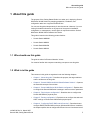
1 About this guide
The purpose of the Getting Started Guide is to assist you in deploying Summit
WM-Series WLAN Solution by mapping preparation, installation, and
configuration tasks into a logical and efficient flow.
You can use this guide independently of other documents. However, if you are
looking for detailed information on any aspect of the system’s installation,
configuration, or management, use this guide in conjunction with the Summit
WM-Series WLAN Switch Software User Guide.
This guide is based on the following product families:
•
Summit Switch WM2000
•
Summit Switch WM200
•
Summit SwitchWM1000
•
Summit Switch WM100
1.1 Who should use this guide
The guide is written for Extreme Networks’ clients.
You must be familiar with computer networking concepts to use this guide.
1.2 What is in this guide
This contents in this guide are organized under the following chapters:
•
Chapter 1, “About this guide”– Describes the purpose, the target audience
and the architecture of this guide.
•
Chapter 2, “Summit WM-Series WLAN Switch Software Solution” – Captures
the essential concepts of the solution.
•
Chapter 3, “Summit WM-Series WLAN Switch configuration”– Explains how
to configure the Summit WM Switch’s settings in order to make it operational.
•
Chapter 4, “Physical ports configuration”– Describes how to configure the
Summit WM Switch’s physical ports.
•
Chapter 5, “Routing configuration”– Explains how to configure the static and
OSPF routings on the Summit WM Switch’s physical ports.
•
Chapter 6, “Configuring DHCP, DNS and IAS services”– Describes how to
configure DHCP, DNS and IAS services on Windows 2003 Server. In addition,
the chapter explains how to configure DHCP service on a Linux-based server.
120385-00 Rev 01, March 2007
Summit WM, Getting Started Guide
7
HWC_GSG_Preface.fm
About this guide
Formatting conventions
•
Chapter 7, “Altitude AP’s configuration”– Explains how to configure and
manage the Altitude APs through the Summit WM Switch.
•
Chapter 8, “WM-AD configuration”– Describes how to create and configure
WM-AD via the Summit WM Switch.
•
Chapter 9, “Availability and Mobility configuration” – Explains how to
configure availability and mobility features via the Summit WM Switch.
1.3 Formatting conventions
The document uses the following formatting conventions to make it easier to find
information and follow procedures:
•
Bold text is used to identify components of the management interface, such
as menu items and section of pages, as well as the names of buttons and text
boxes.
•
•
Monospace font is used in code examples and to indicate text that you type.
•
•
For example: Click Logout.
For example: Type https://<SWM-address>[:mgmt-port>]
The following symbols are used to draw your attention to additional
information:
Note: Notes identify useful information, including reminders, tips, or other
ways to perform a task.
Note: Cautionary notes identify essential information, which if ignored can
adversely affect the operation of your equipment or software.
Note: Warning notes identify essential information, which if ignored can lead
to personal injury.
8
120385-00 Rev 01, March 2007
Summit WM, Getting Started Guide
HWC_GSG_Preface.fm
About this guide
Document feedback
1.4 Document feedback
If you have any problems using this document, please contact the next level of
support:
•
Customers should contact the Extreme Networks Technical Assistance
Center (TAC).
When you call, please have the following information ready. This will help us to
identify the document that you are referring to.
•
Title: Summit WM-Series WLAN Switch Software Getting Started Guide
•
Part Number: 120385-00 Rev 01
120385-00 Rev 01, March 2007
Summit WM, Getting Started Guide
9
HWC_GSG_Preface.fm
About this guide
Document feedback
10
120385-00 Rev 01, March 2007
Summit WM, Getting Started Guide
HWC_GSG_Chapter 1_Overview.fm
Summit WM-Series WLAN Switch Software Solution
Conceptual model
2 Summit WM-Series WLAN Switch Software Solution
This chapter describes the essential concepts of Summit WM-Series WLAN
Switch Software Solution.
The topics in this chapter are organized as follows:
•
Conceptual model
•
Collecting information for installation
2.1 Conceptual model
The Summit WM-Series WLAN Switch Software Solution is an enterprise WLAN
solution that consists of the following components:
•
Summit WM-Series WLAN Switch (Summit WM Switch)
•
Altitude AP
•
Summit WM-Series WLAN Switch Software
2.1.1 Summit WM Switch
The Summit WM Switch is a high-performance server that provides several
functions, including centralized management and configuration of Altitude APs,
user authentication, and advanced radio frequency management.
The Summit WM Switch is driven by Summit WM-Series WLAN Switch Software.
The software resides on the Summit WM Switch and provides an intuitive webbased interface — Extreme Networks Summit WM-Series Console to enable you
to manage the entire wireless network from a wired laptop, or a PC connected to
the network. A command line interface is also available to manage the wireless
network.
The Summit WM Switch is a full-functioning dynamic router that aggregates and
coordinates all Altitude APs and manages client devices.
Some key features of the Summit WM Switch provided in the following sections:
120385-00 Rev 01, March 2007
Summit WM, Getting Started Guide
11
HWC_GSG_Chapter 1_Overview.fm
Summit WM-Series WLAN Switch Software Solution
Conceptual model
2.1.1.1 Web-based centralized management of Altitude APs
The Summit WM Switch enables you to monitor and manage Altitude APs from a
centralized web-based interface called the Extreme Networks Summit WMSeries Console. You can separately configure, enable, or disable each Altitude
AP from the Summit WM Switch using the Extreme Networks Summit WM-Series
Console.
The Extreme Networks Summit WM-Series Console also allows you to group the
APs of similar attributes into one of ten upgrade profiles for the purpose of
deploying software upgrades.You can initiate the software updates on a profile
and the updates will be deployed to each AP in the profile. This saves you from
the cumbersome task of deploying the updates to each AP individually.
2.1.1.2 Virtualized user segmentation
The Summit WM Switch allows you to create and manage unique WM Access
Domain that enables you to group specific mobile users, devices and applications
on the basis of policy class in order to provide unique levels of service, access
permissions, encryption, and device authorization.
A WM-AD segment is a virtual network and each Altitude Access Points can
support multiple WM-AD segments.
WM-AD optimizes the dynamic nature of WLAN mobility as WM-AD groups can
follow users without depending on the physical configuration of the network.
The following is the list of Summit WM Switches and the number of WM-ADs they
can support.
•
Summit Switch WM2000: 64 WM-ADs
•
Summit Switch WM200: 32 WM-ADs
•
Summit Switch WM1000: 50 WM-ADs
2.1.1.3 Summit Switch WM100: 32 WM-ADsAuthentication and
encryption
The Summit WM Switch and Altitude AP work together to support comprehensive
authentication, encryption, and intrusion detection capabilities. A range of robust
security features based upon the 802.11 and WPA2 standards ensure that your
network stays protected.
802.1X mechanism in conjunction with RADIUS and pre-shared key
authentication ensure that only authorized users can access the network.
Other features include Captive Portal for redirected web-based authentication.
12
120385-00 Rev 01, March 2007
Summit WM, Getting Started Guide
HWC_GSG_Chapter 1_Overview.fm
Summit WM-Series WLAN Switch Software Solution
Conceptual model
2.1.1.4 Intrusion detection
The Summit WM Switch allows you to configure Altitude APs to detect rogue
access points on the network by scanning the radio frequency (RF) space at
specific intervals. Scan results are then forwarded to the Summit WM Switch; the
Summit WM Switch processes and presents the data centrally. Rogue detection
data can be viewed via the Extreme Networks Summit WM-Series Console.
2.1.1.5 Automatic assignment of IP addresses to the client
devices
The Summit WM Switch has built-in DHCP server that assigns IP addresses to
the client devices. The Summit WM Switch is also capable of working with an
external DHCP server.
2.1.1.6 Web authentication
The Summit WM Switch has a built-in Captive Portal capability that allows Web
authentication (Web redirection) to take place. The Summit WM Switch is also
capable of working with external Captive Portal.
2.1.2 Altitude AP
Altitude APs are wireless LAN access points that bridge the network traffic
between wireless devices and the Ethernet LAN.
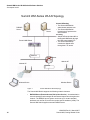
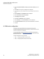
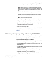
2.1.3 Summit WM-Series WLAN Solution topology
and network elements
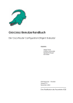
The following figure illustrates a typical configuration with a single Summit WM
Switch and two Altitude APs, each supporting a wireless device. A RADIUS
server on the network provides user authentication, and a DHCP server assigns
IP addresses to the Altitude APs. Network inter-connectivity is provided by the
infrastructure routing and switching devices.
120385-00 Rev 01, March 2007
Summit WM, Getting Started Guide
13
HWC_GSG_Chapter 1_Overview.fm
Summit WM-Series WLAN Switch Software Solution
Conceptual model
Summit WM-Series WLAN Topology
RADIUS
Server
DHCP
Server
Control & Routing
• The Summit WM Switch
authenticates wireless user
• The Summit WM Switch
forwards the IP packet to the
wired network
Tunnelling
• Altitude AP sends data traffic to
the Summit WM Switch through
the UDP tunnel called CTP
• The Summit WM Switch
controls the Altitude APs
through the CTP tunnel
Summit WM Switch
Ethernet
Router
Altitude AP
Altitude AP
Ethernet
Wireless Device
Wireless Device
Figure 1
Summit WM-Series WLAN topology
The Summit WM Switch supports the following network elements.
•
14
RADIUS Server (Remote Access Dial-in User Service) – An authentication
server that assigns and manages ID and Password protection throughout the
network. The RADIUS server system can be set-up for certain standard
attributes such as filter ID, and for the vendor specific attributes (VSAs). The
Summit WM Switch supports external RADIUS server.
120385-00 Rev 01, March 2007
Summit WM, Getting Started Guide
HWC_GSG_Chapter 1_Overview.fm
Summit WM-Series WLAN Switch Software Solution
Conceptual model
•
DHCP Server (Dynamic Host Configuration Protocol) – A server that
assigns the IP addresses, gateways, and subnet masks dynamically. The
external DHCP server depicted in Figure 2-1 is primarily utilized to provide
addresses to infrastructure equipment such as APs. The IP addresses to the
mobile devices are provided by the built-in DHCP server of Summit WM
Switch. You can also configure the Summit WM Switch to relay DHCP
requests to the external DHCP server.
•
SLP (Service Location Protocol) – A service discovery protocol that allows
computers and other devices to find services in a local area network without
prior configuration. The client applications are user agents and services that
are advertised by a service agent. In larger installations, a directory agent
collects information from service agents and creates a central repository. SLP
is one of the several modes that the Summit WM Switch uses to discover the
Altitude APs.
•
Domain Name Server – A server that translates the domain names into IP
addresses. The DNS is used as an alternative mechanism for the automatic
discovery process. The Summit WM Switch, its software, and the APs rely on
the DNS for Layer 3 deployments. In addition, DNS is utilized for the static
configuration of APs. The Summit WM Switch can be registered in DNS to
provide DNS assisted AP discovery.
2.1.4 Discovery mechanism in Summit WM-Series
WLAN Solution
The Summit WM-Series WLAN Solution provides auto-discovery capabilities
between the following components:
•
Altitude APs and Summit WM Switch
•
Mobility manager and mobility agents (For more information, see Chapter 9,
“Availability and Mobility configuration”.)
2.1.4.1 Discovery mechanism between Altitude AP and
Summit WM Switch
The Altitude APs discover the Summit WM Switch by one of the following modes:
•
SLP (Multicast and Unicast) – For more information, see SLP’s description in
Section 2.1.4, “Discovery mechanism in Summit WM-Series WLAN Solution”,
on page 15.
•
DNS – For more information, see Domain Name Server’s description in
Section 2.1.4, “Discovery mechanism in Summit WM-Series WLAN Solution”,
on page 15.
120385-00 Rev 01, March 2007
Summit WM, Getting Started Guide
15
HWC_GSG_Chapter 1_Overview.fm
Summit WM-Series WLAN Switch Software Solution
Conceptual model
•
Static IP address configuration – Summit WM Switch’s IP address is defined
in Altitude AP configuration. For more information, see Section 7.5,
“Configuring static IP address for Altitude APs”, on page 86.
2.1.4.2 Discovery mechanism between mobility manager and
mobility agents
The mobility agents discover the mobility manager by one of the following modes:
•
SLP with DHCP Option 78 – The mobility agent on each Summit WM Switch
discovers the address of the mobility manager using DHCP Option 78.
•
Direct IP address option – Defined while configuring the mobility agent. By
explicitly defining the manager’s IP address while configuring the agents,
enables the manager and agents to find each other directly without using the
SLP discovery mechanism.
2.1.5 DHCP usage scenarios in Summit WM-Series
WLAN Solution
DHCP usage has four scenarios in Summit WM-Series WLAN Solution:
•
DHCP for Altitude APs
•
DHCP for WM-AD
•
DHCP relay for WM-AD
•
DHCP for traffic bridged locally at Altitude AP
The following sections explain the four scenarios with the help of graphical
illustrations.
16
120385-00 Rev 01, March 2007
Summit WM, Getting Started Guide
HWC_GSG_Chapter 1_Overview.fm
Summit WM-Series WLAN Switch Software Solution
Conceptual model
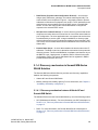
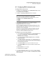
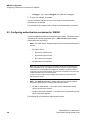
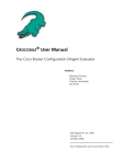
2.1.5.1 DHCP for Altitude APs
DNS Server
DHCP Server
Summit WM Switch
* The Altitude AP
requests an IP
address from the
external DHCP
server
* The DHCP server
responds by
sending the IP
address to the
Altitude AP
Altitude AP
Altitude AP
Wireless
Device
Wireless
Device
Figure 2
DHCP for Altitude APs
You can use Windows 2003 server, amongst others, for deploying DHCP service
for Altitude APs. For more information, see Section 6.1, “DHCP service
configuration”, on page 61.
120385-00 Rev 01, March 2007
Summit WM, Getting Started Guide
17
HWC_GSG_Chapter 1_Overview.fm
Summit WM-Series WLAN Switch Software Solution
Conceptual model
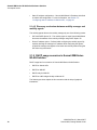
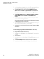
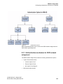
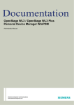
2.1.5.2 DHCP for WM-AD
DNS Server
DHCP Server
* The wireless device
requests an IP address from
Altitude AP
* The Altitude AP forwards
the request to Summit WM
Switch via WM-AD tunnel
Summit WM Switch
* The built-in DHCP server
in Summit WM Switch
responds by sending the IP
address to Altitude AP
* The Altitude AP sends the
IP address to the wireless
device.
Altitude AP
Wireless
Device
Figure 3
Wireless
Device
DHCP for WM-AD
The DHCP configuration for WM-AD is done via Summit WM Switch. For more
information, see Section 8.2, “Creating and configuring a Routed WM-AD”, on
page 97.
18
120385-00 Rev 01, March 2007
Summit WM, Getting Started Guide
HWC_GSG_Chapter 1_Overview.fm
Summit WM-Series WLAN Switch Software Solution
Conceptual model
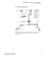
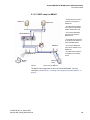
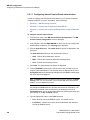
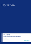
2.1.5.3 DHCP relay for WM-AD
DNS Server
DHCP Server
* A wireless device sends a
request for IP address to
Altitude AP
* The Altitude AP forwards
the request to Summit WM
Switch via WM-AD tunnel
* The Summit WM Switch
relays the request to the
DHCP server
Summit WM Switch
* The DHCP server responds
by sending the IP address to
the Summit WM Switch
Altitude AP
* The Altitude AP sends the
IP address to the wireless
device
Altitude AP
Wireless
Device
* The Summit WM Switch
relays the IP address to the
Altitude AP
Wireless
Device
Figure 4
DHCP relay for WM-AD
The DHCP relay configuration is done via Summit WM Switch. For more
information, see Section 8.2, “Creating and configuring a Routed WM-AD”, on
page 97.
120385-00 Rev 01, March 2007
Summit WM, Getting Started Guide
19
HWC_GSG_Chapter 1_Overview.fm
Summit WM-Series WLAN Switch Software Solution
Summit WM Switch’s physical description
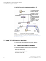
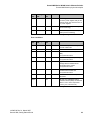
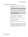
2.1.5.4 DHCP for traffic bridged locally at Altitude AP
DNS Server
Summit WM Switch
* A wireless device sends a
request for IP address to
Altitude AP
* The Altitude AP forwards
the request to the DHCP
server
* The DHCP server responds
by sending the IP address to
the Altitude AP
* The Altitude AP sends the
IP address to the wireless
device
Altitude AP
Altitude AP
Wireless
Device
Figure 5
DHCP Server
Wireless
Device
DHCP for traffic bridged locally at Altitude AP
The DHCP relay configuration is done via Summit WM Switch. For more
information, see Section 8.4, “Creating and configuring a Bridge Traffic Locally At
WAP WM-AD”, on page 101.
2.2 Summit WM Switch’s physical description
This section provides a physical description of the Summit WM Switch.
2.2.1 Summit Switch WM2000 front panel
The Summit Switch WM2000is composed of the following three cards:
20
•
Media Flash 1000 (MF 1000)
•
Network Processor 4000 (NP 4000)
•
Supervisor 1100 (SC 1100)
120385-00 Rev 01, March 2007
Summit WM, Getting Started Guide
HWC_GSG_Chapter 1_Overview.fm
Summit WM-Series WLAN Switch Software Solution
Summit WM Switch’s physical description
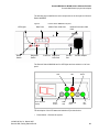
The following figure identifies the main components on the front panel of Summit
Switch WM2000
Figure 6
LED Lights
Reset
Switch
Summit Switch WM2000 front panel
Data Ports
Diagnostic
Switch
Media Flash 1000 Card
Network Processor 4000
Card
Console
Port
RJ45 Port Supervisor
1100 Card
Console Adapter
The Summit Switch WM2000 has five LED lights and two switches on its front
panel.
ACT
LED
Seven-Segment
Display
Figure 7
Reset
Switch
ERROR
LED
RUN
LED
Diagnostic
Switch
WARNING
LED
INT
LED
Summit Switch WM2000’s LED lights and switches
The description of the LED states and switches is provided below:
•
120385-00 Rev 01, March 2007
Summit WM, Getting Started Guide
Reset Switch – Reboots the system.
21
HWC_GSG_Chapter 1_Overview.fm
Summit WM-Series WLAN Switch Software Solution
Summit WM Switch’s physical description
•
RUN LED – Indicates the CPU’s initialization has completed and the system
is ready to provide application level services.
•
ACT LED – Indicates the system’s software is in active running state.
•
WARNING/ERROR LEDs – Indicate a problem in the running state of the
system.
•
•
Whenever either of the alarm LEDs is lit, the seven-segment display
provides the corresponding code point for the error indication. When the
system is fully active and running, the console displays the letter A as
seen in Figure 7.
Diagnostic Switch – Pressing the Reset and Diagnostic switch
simultaneously reboots the system in diagnostic mode.
Note: The diagnostic switch should be used only upon the request of a service
technician.
•
INT LED – Not used in the current release.
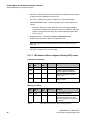
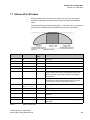
2.2.1.1 LED states and Seven Segment Display (SSD) codes
Application initialization
Active Warning
LED
LED
SSD Code
Condition
Green
0
Application initialization started.
Green
1
Forwarding Engine initialization
complete. Application initialization.
Green
A
Application initialization complete.
System active.
Green
H
System halted. Administrator requested
halting of system.
Table 1
Error
LED
LED states and SSD codes during application initialization
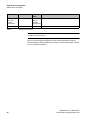
Warning conditions
Active Warning
LED
LED
SSD Code
Condition
Green
Yellow
1
High temperature reached.
Green
Yellow
2
Fan unit failure. Rotation counter
indicates zero speed for one of the
lateral trays. May be the result of fan
tray removal.
Table 2
22
Error
LED
LED states and SSD codes during warning conditions
120385-00 Rev 01, March 2007
Summit WM, Getting Started Guide
HWC_GSG_Chapter 1_Overview.fm
Summit WM-Series WLAN Switch Software Solution
Summit WM Switch’s physical description
Active Warning
LED
LED
Error
LED
SSD Code
Condition
Green
Yellow
3
Power supply failure. Failed to detect
one of the power supplies. May be the
result of the fan tray removal of one of
the power supplies.
Green
Yellow
4
FDD low sector count (40 backup
sectors remaining).
Green
Yellow
5
FDD extremely low sector count (20
backup sectors remaining)
Table 2
LED states and SSD codes during warning conditions
Error conditions:
Active Warning
LED
LED
Error
LED
SSD Code
Condition
Green
Red
1
Failed to identify FDD. Possibly due to
removal of FDD card.
Green
Red
2
Failed to initialize NPE card.
Green
Red
3
Critical threshold reached (95C for
NPE).
The system will reboot.
Green
Red
4
Full fan assembly failure (both trays).
The system will reboot.
Green
Red
5
Application initialization failure. Startup
manager failed to initialize all the
components of the system.
The system will reboot.
Green
Red
6
Lost connectivity with ethernet interface.
Possible failure of NPE card.
The system will reboot.
Green
Red
7
MF 1000 card failure. Backup sectors
exhausted.
Green
Red
8
NP 4000 card initialization failure.
Firmware self test (BIST) has detected
failure in one or more components
(memory, bus, interconnects)
Table 3
120385-00 Rev 01, March 2007
Summit WM, Getting Started Guide
LED states and SSD codes during error conditions
23
HWC_GSG_Chapter 1_Overview.fm
Summit WM-Series WLAN Switch Software Solution
Summit WM Switch’s physical description
2.2.2 Summit Switch WM2000 back panel
The following figure identifies the main components on the back panel of Summit
WM Switch WM2000.
Redundant
Power Supply
Power Switches
Figure 8
Summit Switch WM2000 back panel
Figure 9
Note: The hardware for the Summit Switch WM200 and the Summit Switch WM2000 are
identical. For more information, see Section 2.2.1, “Summit Switch WM2000 front panel”,
on page 20 and Section 2.2.2, “Summit Switch WM2000 back panel”, on page 24.
2.2.3 Summit Switch WM1000 front panel
The Summit Switch WM1000 doesn’t have any component on the front panel
except two LED lights. These two LED lights are:
•
STATUS LED – For more information, see the STATUS LED description in
Section 2.2.4, “Summit Switch WM1000 back panel”, on page 25.
•
ACTIVITY LED – For more information, see the ACTIVITY LED description in
Section 2.2.4, “Summit Switch WM1000 back panel”, on page 25.
These two LED lights are also located on the back panel of the Summit Switch
WM1000.
24
120385-00 Rev 01, March 2007
Summit WM, Getting Started Guide
HWC_GSG_Chapter 1_Overview.fm
Summit WM-Series WLAN Switch Software Solution
Summit WM Switch’s physical description
2.2.4 Summit Switch WM1000 back panel
The following figure identifies the main components on the back panel of Summit
Switch WM1000.
Power Switch
Data Ports
Console Port
LED Lights
Management Port
Redundant Power Supply
Note: Summit Switch WM1000 back panel The Summit Switch WM1000may have a
standard power supply (one power supply) or a redundant power supply (two power
supplies).
The Summit Switch WM1000has three LED lights on its back panel.
LINK-UP
LED
Figure 10
STATUS
LED
ACTIVITY
LED
Summit Switch WM1000 LED lights
The description of the LED states is provided below:
•
120385-00 Rev 01, March 2007
Summit WM, Getting Started Guide
LINK-UP LED – Displays the link status of management port Ethernet link as
seen by the system’s software. This LED is located only on the back panel of
the Summit Switch WM1000.
25
HWC_GSG_Chapter 1_Overview.fm
Summit WM-Series WLAN Switch Software Solution
Summit WM Switch’s physical description
•
STATUS LED – Indicates the normal state of the Summit WM Switch as seen
by the system’s software. This LED covers all stages of the Summit WM
Switch, ranging from restarting, to shutting-down. As long as the Summit WM
Switch is running normally, this LED will remain lit. The STATUS LED is
located on the back panel as well as the front panel.
•
ACTIVITY LED – Indicates the amount of traffic carried to and from the
Altitude APs. The ACTIVITY LED is located on the back panel as well as the
front panel.
2.2.5 Summit Switch WM100 front panel
The Summit Switch WM100does not have any component on the front panel
except two LED lights.
The description of the LED states is provided below:
•
STATUS LED– For more information, see the STATUS LED description in
Section 2.2.4, “Summit Switch WM1000 back panel”, on page 25.
•
ACTIVITY LED – For more information, see the ACTIVITY LED description in
Section 2.2.4, “Summit Switch WM1000 back panel”, on page 25.
The STATUS LED is located on the back panel as well as the front panel of the
Summit Switch WM100.
26
120385-00 Rev 01, March 2007
Summit WM, Getting Started Guide
HWC_GSG_Chapter 1_Overview.fm
Summit WM-Series WLAN Switch Software Solution
Summit WM Switch’s physical description
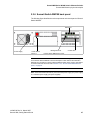
2.2.6 Summit Switch WM100 back panel
The following figure identifies the main components on the back panel of Summit
Switch WM100.
Data Ports
Power Supply
Power Switch
Figure 11
Management Port
Console Port
Summit Switch WM100 back panel
Note: The Summit Switch WM100 has the same number of LED lights on the back panel
as the Summit Switch WM1000. The LED description of their state is also identical to
WM1000. For information on Summit Switch WM100’s LEDs’ states, see the descriptions
of STATUS LED and ACTIVITY LED in Section 2.2.4, “Summit Switch WM1000 back
panel”, on page 25.
Note: The Summit Switch WM100 may have a standard power supply (one power supply)
or a redundant power supply (two power supplies).
120385-00 Rev 01, March 2007
Summit WM, Getting Started Guide
27
HWC_GSG_Chapter 1_Overview.fm
Summit WM-Series WLAN Switch Software Solution
Collecting information for installation
2.3 Collecting information for installation
You must use the following table to document all the pertinent information about
the Summit WM Switch before starting the installation process.
Some of the information listed in the table may not be relevant to your network
configuration. You must only record the information that is pertinent to your
network configuration.
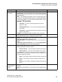
Configuration data Description
Your entry
• Unused IP address in the 192.168.10.0/24 subnet – This IP
Accessing the
address must be assigned to the Ethernet port of your laptop
Summit WM
computer. You can use any IP address between 192.168.10.2 and
Switch for the first
192.168.10.255.
time
• Factory default IP address of Summit WM Switch – The factory
default IP address is https//192.168.10.1:5825. You must
type this IP address in the address bar of your Web browser when
you access the Summit WM Switch for the first time.
• Login Information – The login information is as follows:
•
User Name: admin
•
Password: abc123
Management Port • Hostname – Specifies the name of the Summit WM Switch.
information
• Domain – Specifies the IP domain name of the enterprise
network.
• Management IP Address – The new IP address for the Summit
WM Switch’s management port. Change the value in this text box
to the IP address assigned to the Summit WM Switch’s
management port by your network administrator.
• Subnet Mask – The subnet mask for the IP address to separate
the network portion from the host portion of the address (typically
255.255.255.0)
• Management Gateway – The default gateway of the network.
• Primary DNS – The primary DNS server used by the network.
• Secondary DNS – The secondary DNS server used by the
network.
Hardware
information
• MAC Address – MAC address of the Summit WM Switch’s
management port
• Serial # – The Summit WM Switch’s serial #.
License Key (File) An .xml file that is provided along with the product. This file must be
applied to the product to enable all the functionalities.
Table 4
28
Information gathering table
120385-00 Rev 01, March 2007
Summit WM, Getting Started Guide
HWC_GSG_Chapter 1_Overview.fm
Summit WM-Series WLAN Switch Software Solution
Collecting information for installation
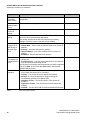
Configuration data Description
Data Ports
information
Your entry
• IP address – IP address of the physical ethernet port.
• Subnet mask – Subnet mask for the IP address, which separates
the network portion from the host portion of the address (typically
255.255.255.0).
• MTU – The maximum transmission unit or maximum packet size
for this port. The default setting is 1500. If you change this setting,
and are using OSPF, you must make sure that the MTU of each
port in the OSPF link matches.
• Function – The port’s function.
•
Host Port – A port for connecting Altitude APs with no
dynamic routing.
•
Third-party AP Port – A port to which the third-party AP is
connected.
•
Router Port – A port that connects to an upstream, next-hop
router in the network.
• VLAN ID – The ID of the VLAN to which the AP is connected.
Static Routing
Static IP address – The static IP address that is assigned to the
Summit WM Switch when it is configured for static routing.
OSPF Routing
• Router ID – The router ID is its own IP address. You must record
the Summit WM Switch’s IP address here.
• Area ID of OSPF – Id of OSPF’s area. 0.0.0.0. is the main area in
OSPF.
• OSPF Authentication Password – If you select Authentication
type as Password, then you will need a password.
DHCP Service
• IP address range – This is the range from which the IP address
will be distributed across the network.
•
Start IP address – This is the start IP address of the range.
•
End IP address – This is the end IP address of the range.
• Lease duration – The DHCP server assigns a client an IP address for a
given amount of time. The amount of time for which the IP address can
be given is called lease duration.
IP Address for
installing DHCP
service
Table 4
•
Days – The number of days for which the lease can be given.
•
Hours – The number of hours for which the lease can be
given.
•
Minutes – The number of minutes for which the lease can be
given.
IP Address – If you are using WM-AD, you will need the WM-AD’s
IP address.
If you are not using WM-AD, you will need the Summit WM Switch IP
address.
Information gathering table
120385-00 Rev 01, March 2007
Summit WM, Getting Started Guide
29
HWC_GSG_Chapter 1_Overview.fm
Summit WM-Series WLAN Switch Software Solution
Collecting information for installation
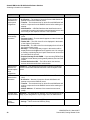
Configuration data Description
WM-AD gateway
for installing
DHCP service
Your entry
WM-AD gateway – If you are using WM-AD, you will need the WMAD gateway.
Domain name for Domain name – Your organization’s domain name.
installing DHCP
service
Windows 2003
Server’s IP
address
IP address – The IP address of Windows 2003 Server.
SLP DA’s IP
address
Hexa values of SLP DA’s IP address – The Altitude APs use the
SLP DA to discover the Summit WM Switch .
The mobility agents use the SLP DA to discover the mobility
manager. The hexa values of the SLP DA’s IP address.
Internet Protocol
configuration for
DNS Service in
Windows 2003
server
• Static IP address – Windows 2003 server’s static IP address.
• Subnet Mask – Subnet mask of Windows 2003 server’s static IP
address.
• Gateway – Windows 2003 server’s gateway.
• ISP’s IP address – Your ISP’s (Internet Service Provider) IP
address.
• IP address– Summit WM Switch’s IP address.
Port information • Authentication Port – Summit WM Switch’s used to access the
IAS service.
for installing IAS
in Windows 2003 • Accounting Port – Type the Summit WM Switch’s port # that is
used to access the accounting service.
server
The values you record here should match what you define in the Port
text box of Auth section in the Acc & Acct tab of Summit WM
Switch’s WM-AD screen.
Altitude AP’s
properties
Table 4
30
• Summit WM Switch’s Port # – Summit WM Switch’s ethernet
port to which the Altitude AP is connected.
• Country – The country where the Altitude AP operates.
• Serial # – A unique identifier that is assigned during the
manufacturing process of the Altitude APs.
• Hardware version – The current version of the Altitude AP
hardware.
• Application version – The current version of the Altitude AP
software.
• VLAN ID – The ID of the VLAN on which the Altitude AP operates.
Information gathering table
120385-00 Rev 01, March 2007
Summit WM, Getting Started Guide
HWC_GSG_Chapter 1_Overview.fm
Summit WM-Series WLAN Switch Software Solution
Collecting information for installation
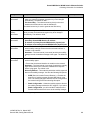
Configuration data Description
Your entry
Local DHCP
• Gateway – The Summit WM Switch advertises this address to the
Server In Routed
wireless devices when they sign on and get a dynamic IP address.
WM-AD
The gateway corresponds to the IP address that is communicated
to mobile users.
• Subnet mask – Subnet mask for the gateway IP address to
separate the network portion from the host portion of the address
(typically 255.255.255.0).
• Address range – The range from which the IP addresses are
provided to the wireless devices that use the WM-AD.
• External enterprise domain name – The external enterprise
domain name.
• DNS Server IP address– The IP address of the domain name
server on the enterprise network.
DHCP Relay in
Routed WM-AD
• Gateway – The Summit WM Switch advertises this address to the
wireless devices when they sign on and get a dynamic IP address.
The gateway corresponds to the IP address that is communicated
to mobile users.
• Subnet mask – Subnet mask for the gateway IP address to
separate the network portion from the host portion of the address
(typically 255.255.255.0).
• DHCP Server IP address(es) – IP addresses of the external
DHCP servers on the enterprise network.
Next Hop Routing • Next hop IP address – The next-hop IP identifies the target
for Routed WMdevice to which all WM-AD (user traffic) will be forwarded to. NextAD
hop definition supersedes any other possible definition in the
routing table.
• OSPF routing cost – The OSPF cost value provides a relative
cost indication to allow upstream routers to calculate whether or
not to use the Summit WM Switch as a better fit, or lowest cost
path to reach the devices in a particular network. The higher the
cost, the less likely that the Summit WM Switch will be chosen as
a route for traffic, unless that Summit WM Switch is the only
possible route for that traffic
VLAN Information • VLAN ID – The ID # of VLAN that is mapped to a Summit WM
Switch interface.
for Bridge Traffic
• Interface – The name of the interface to which the VLAN is
Locally at SWM
mapped.
WM-AD
• Interface IP address – The interface’s IP address.
• Mask – The subnet mask of the WM-AD.
VLAN ID for
Bridge traffic
locally at WAP
WM-AD
Table 4
• VLAN ID – The ID #of VLAN that is mapped to a Summit WM
Switch interface.
Information gathering table
120385-00 Rev 01, March 2007
Summit WM, Getting Started Guide
31
HWC_GSG_Chapter 1_Overview.fm
Summit WM-Series WLAN Switch Software Solution
Collecting information for installation
Configuration data Description
Your entry
Authentication
and Accounting
information for
captive portal
configuration
• Port – Used to access the RADIUS server. The default is 1812.
• # of Retries – The number of times the Summit WM Switch will
attempt to access the RADIUS server.
• Timeout – The maximum time for which Summit WM Switch will
wait for a response from the RADIUS server before making a reattempt.
• NAS Identifier – A RADIUS attribute that identifies the server
responsible for passing information to the designated servers and
then acting on the response returned. This is optional.
Internal captive
portal settings
information
• Login Label – The text that will appear as a label for the user
name.
• Password Label – The text that will appear as a label for the user
password text box.
• Header URL – The URL of the file to be displayed in the header
of the Captive Portal screen.
• Footer URL – The URL of the file to be displayed in the footer of
the Captive Portal screen.
• Message – The message that you type in this text box will be
displayed above the Login text box to greet the user. You can type
a message, explaining why the Captive Portal screen is used and
the instructions for the user.
• Replace Gateway IP with FQDN – If you are using FQDN (Fully
Qualified Domain Name) as the gateway address, document the
FQDN.
• Default Redirection URL – The URL to which the wireless
devices will be directed before authentication.
Shared Secret
Password for
external captive
portal
configuration
Password – This password encrypts the information exchanged
between the Summit WM Switch and the external Captive Portal
server.
MAC-based
authentication
information
• Port – The port used to access the RADIUS server. The default is
1812.
• # of Retries – Number of times the Summit WM Switch will
attempt to access the RADIUS server.
• Timeout – The maximum time for which Summit WM Switch will
wait for a response from the RADIUS server before making a reattempt.
• NAS IP Address – IP address of the network access server
(NAS).
Exception filter
rules information
IP/subnet – The destination IP address. You can also specify the IP
range, a port designation or a port range on the IP address here.
Static WEP
privacy
information
• WEP Key Length – Size of a WEP key.
• Strings – This is the secret WEP key string.
Table 4
32
Information gathering table
120385-00 Rev 01, March 2007
Summit WM, Getting Started Guide
HWC_GSG_Chapter 1_Overview.fm
Summit WM-Series WLAN Switch Software Solution
Collecting information for installation
Configuration data Description
Your entry
WPA-PSK privacy • Broadcast re-key interval – The time interval (in seconds) after
information
which you want the broadcast encryption key to be changed
automatically. The default is 3600.
• Pre-shared Key – The shared secret key that is to be used
between the wireless device and the Altitude AP.
The shared secret key is used to generate the 256 bit key.
Dynamic WEP
privacy
information
Broadcast re-key interval – The time interval (in seconds) after
which you want the broadcast encryption key to be changed
automatically. The default is 3600.
Availability
information
•
•
•
•
Primary Summit WM Switch’s IP address
Secondary Summit WM Switch’s IP address
IP address of primary Summit WM Switch’s physical port
IP address of secondary Summit WM Switch’s physical port
Mobility manager • Port – The interface of the Summit WM Switch that is to be used
information
as the mobility manager. Ensure that the selected interface is
routable on the network.
• Heartbeat – The time interval (in seconds) at which the mobility
manager sends a heartbeat message to the agent. The default is
5.
Mobility agent
information
• Port – The interface of the Summit WM Switch that is to be used
as the mobility agent.
Ensure that the selected interface is routable on the network.
• Heartbeat – The time interval (in seconds) for which the mobility
agent should wait for the connection establishment response
before trying again. The default is 60.
• Discovery Method – The method by which the mobility agent will
discover the mobility manager. You have the following two options:
Table 4
•
SLPD (Service Location Protocol Daemon) – Enables the
discovery of mobility manager Summit WM Switch, using
SLP. The mobility manager's address must be configured on
the network using SLP when selecting this option.
•
Static Configuration – Allows the mobility agent to discover
the mobility manager without the SLP support. If you select
Static Configuration, you will need the IP address of the
Summit WM Switch that will serve as the mobility manager.
Information gathering table
120385-00 Rev 01, March 2007
Summit WM, Getting Started Guide
33
HWC_GSG_Chapter 1_Overview.fm
Summit WM-Series WLAN Switch Software Solution
Collecting information for installation
34
120385-00 Rev 01, March 2007
Summit WM, Getting Started Guide
HWC_GSG_Chapter 2_Default_Settings.fm
Summit WM-Series WLAN Switch configuration
Accessing the Summit WM-Series WLAN Switch for the first time
3 Summit WM-Series WLAN Switch configuration
This chapter explains how to configure the Summit WM-Series WLAN Switch’s
settings to make it operational.
The topics in this chapter are organized as follows:
•
Accessing the Summit WM-Series WLAN Switch for the first time
•
Connecting the Summit WM Switch to the enterprise network
•
Changing the administrator password
•
Configuring the network time
•
Generating a software license key
•
Applying a license key
3.1 Accessing the Summit WM-Series WLAN Switch for the first time
You can access the Summit WM-Series WLAN Switch (Summit WM Switch) by
using a laptop computer with a Web browser.
To access the Summit Switch using a web-enabled laptop:
1. Connect the Summit WM Switch’s management port to the web-enabled
laptop computer with a cross-over RJ 45 Ethernet cable.
2. Statically assign an unused IP address in the 192.168.10.0/24 subnet for the
Ethernet port of the laptop computer.
You can use any IP address between 192.168.10.2 and 192.168.10.255.
3. Launch your web browser.
120385-00 Rev 01, March 2007
Summit WM, Getting Started Guide
35
HWC_GSG_Chapter 2_Default_Settings.fm
Summit WM-Series WLAN Switch configuration
Accessing the Summit WM-Series WLAN Switch for the first time
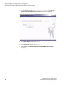
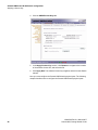
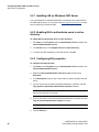
4. In the address bar, type https//192.168.10.1:5825.The Extreme
Networks Summit WM-Series Console login screen is displayed.
5. In the User Name text box, type admin.
6. In the Password text box, type abc123.
7. Click Login. The Extreme Networks Summit WM-Series Console is
displayed.
36
120385-00 Rev 01, March 2007
Summit WM, Getting Started Guide
HWC_GSG_Chapter 2_Default_Settings.fm
Summit WM-Series WLAN Switch configuration
Accessing the Summit WM-Series WLAN Switch for the first time
Note: In the footer of the Extreme Networks Summit WM-Series Console, the
following is displayed:
•[host name | product name | up time]
•For example, [WM2000 | WM2000 | 1 days, 1:11]. If there is no key
(unlicensed), UNLICENSED is displayed besides the software version.
•User is the user id you used to login in. For example, admin.
•Port Status is the connectivity state of the port. M is for the Management
interface, which is on eth0 and the numbered lights reflect the esa ports on
the system. Green indicates the interface is active and running. Red indicates
the interface is down.
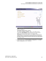
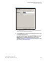
8. From the main menu, click Summit Switch Configuration. The Summit
Switch Configuration screen is displayed.
120385-00 Rev 01, March 2007
Summit WM, Getting Started Guide
37
HWC_GSG_Chapter 2_Default_Settings.fm
Summit WM-Series WLAN Switch configuration
Accessing the Summit WM-Series WLAN Switch for the first time
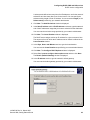
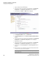
9. In the left pane, click IP Addresses. The factory default settings for the
Summit Switch are displayed.
38
120385-00 Rev 01, March 2007
Summit WM, Getting Started Guide
HWC_GSG_Chapter 2_Default_Settings.fm
Summit WM-Series WLAN Switch configuration
Accessing the Summit WM-Series WLAN Switch for the first time
Note: Only the following models support VLAN:
• Summit Switch WM2000
• Summit Switch WM200
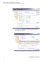
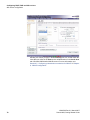
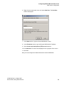
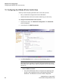
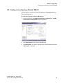
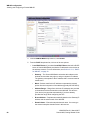
10. In the Management Port Settings section, click Modify. The System Port
Configuration screen is displayed.
11. Type the following information:
120385-00 Rev 01, March 2007
Summit WM, Getting Started Guide
•
Hostname – Specifies the name of the Summit Switch by which it will be
known. You must assign a unique name for the Summit Switch.
•
Domain – Specifies the IP domain name of the enterprise network.
•
Management IP address – Specifies the new IP address for the Summit
WM Switch’s port. Change the value in this text box to the IP address
assigned to the Summit WM Switch’s management port by your network
administrator.
•
Subnet Mask – Specifies the subnet mask for the Summit WM Switch’s
management port. Change the value in this text box to the value provided
by your network administrator.
39
HWC_GSG_Chapter 2_Default_Settings.fm
Summit WM-Series WLAN Switch configuration
Connecting the Summit WM Switch to the enterprise network
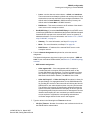
•
Management Gateway – Specifies the default gateway of the network as
provided by the network administrator.
•
Primary DNS – Specifies the primary DNS server used by the network as
provided by your network administrator as provided by your network
administrator. This field is optional.
•
Secondary DNS – Specifies the secondary DNS server used by the
network as provided by your network administrator. This field is optional.
12. Click OK.
Note: The Web connection between the computer and the Summit Switch is lost. The
IP addresses are now set to the network you defined.
Now you must connect the Summit Switch to the enterprise network. The
following section explains how to connect the Summit Switch to the enterprise
network.
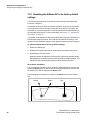
3.2 Connecting the Summit WM Switch to the enterprise network
To connect the Summit Switch to the enterprise network:
1. Disconnect your laptop computer from the Summit Switch management port.
2. Connect the Summit Switch management port to the enterprise Ethernet
LAN. The Summit Switch resets automatically.
3. Log on to the Extreme Networks Summit WM-Series Console from any
computer on the enterprise network. Type the following URL in a browser to
access the Extreme Networks Summit WM-Series Console: tap://<IP
Address>:5825
Before you proceed further, you must change the default administrator password.
The following section explains how to change the default administrator password.
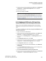
3.3 Changing the administrator password
To change the administrator password:
1. Login on the Summit Switch using the default administrator password.
2. From the main menu, click Summit Switch Configuration. The Summit
Switch Configuration screen is displayed.
3. In the left, click Management Users.
4. In the user_admin table, click admin.
40
120385-00 Rev 01, March 2007
Summit WM, Getting Started Guide
HWC_GSG_Chapter 2_Default_Settings.fm
Summit WM-Series WLAN Switch configuration
Configuring the network time
5. In the Modify User Password text box, type the new administrator password.
6. In the Modify User Confirm Password text-box, retype the new
administrator password.
7. Click Change Password.
3.4 Configuring the network time
The internal clocks of the Summit Switch and Altitude APs on a network may
differ. You must synchronize the clocks of the Summit Switch, and the Altitude
APs in order for the system to operate properly.
The synchronization of clocks ensures accuracy in usage logs of the Summit
Switch.
The Summit Switch provides you the following two options to synchronize the
clocks of Summit Switch and the Altitude APs:
•
Using the system’s time – The system’s time is the Summit Switch’s time.
•
Using the network time protocol (NTP) – The Network Time Protocol is a
protocol for synchronizing the clocks of computer systems over packetswitched data networks.
3.4.1 Configuring the network time using the
system’s time
To configure the network time, using the system’s time:
1. Login on the Summit Switch. The Extreme Networks Summit WM-Series
Console screen is displayed.
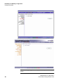
2. Click Summit Switch Configuration. The Summit Switch Configuration
screen is displayed.
120385-00 Rev 01, March 2007
Summit WM, Getting Started Guide
41
HWC_GSG_Chapter 2_Default_Settings.fm
Summit WM-Series WLAN Switch configuration
Configuring the network time
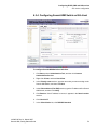
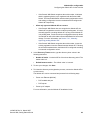
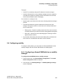
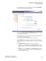
3. In the left pane, click Network Time. The Network Time screen is displayed.
4. From the Continent or Ocean drop-down list, click the appropriate largescale geographic grouping for the time zone.
5. From the Country drop-down list, click the appropriate country for the time
zone. The contents of the drop-down list change, based on the selection in
the Continent or Ocean drop-down list.
6. From the Time Zone Region drop-down list, click the appropriate time zone
region for the selected country.
7. Click Apply Time Zone.
8. Select the Use System Time radio button.
You can modify the system’s date and time by changing the entries in the Use
System Time text box. The date is in mm-dd-yyyy format and the time is in
hh:mm format.
9. Click Apply.
10. Reboot the Summit Switch. The WLAN network time is synchronized in
accordance with the Summit Switch’s time.
42
120385-00 Rev 01, March 2007
Summit WM, Getting Started Guide
HWC_GSG_Chapter 2_Default_Settings.fm
Summit WM-Series WLAN Switch configuration
Generating a software license key
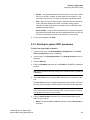
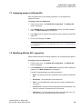
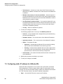
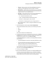
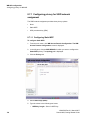
3.4.2 Configuring the network time using the NTP
To configure the network time using the NTP:
1. Perform Step 1 to Step 7 of Section 3.4.1, “Configuring the network time using
the system’s time”.
2. Select Use NTP radio button.
3. In the Time Server 1 text box, type the IP address or FQDN (Full Qualified
Domain Name) of a NTP Time Server that is accessible on the enterprise
network.
4. Repeat Step 3 for Time Server2 and Time Server3 text boxes.
If the system is not able to connect to the Time Server 1, it will attempt to
connect to the additional servers that have been specified in Time Server 2
and Time Server 3 text boxes.
5. Click Apply.
6. Reboot the Summit Switch. The WLAN network time is synchronized in
accordance with the specified time server.
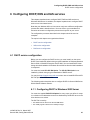
To ensure that all the functionalities are enabled, you must generate a software
license key and apply it to the Summit WM Switch.
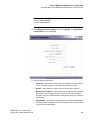
3.5 Generating a software license key
The license key is generated through the web-based Central Licensing Server
(CLS).
You must have the following information before you start the license generation
process:
•
CLS URL – Is provided in the Summit WM Switch Base Software Activation
document.
•
Login information (User Name and Password) – Is provided in the Summit
WM Switch Base Software Activation document.
•
MAC Address – Locate the MAC address on the rear panel of the Summit WM
Switch.
•
Serial Number – Locate the serial number on the rear panel of the Summit
WM Switch.
120385-00 Rev 01, March 2007
Summit WM, Getting Started Guide
43
HWC_GSG_Chapter 2_Default_Settings.fm
Summit WM-Series WLAN Switch configuration
Generating a software license key
•
Regulatory Domain – Is a set of local regulations that control the Altitude APs’
frequencies and power output. The regulations are specific to geographic
locations. If you are located in North America, you are controlled by the North
American Regulatory Domain. You must find out what is your regulatory
domain.
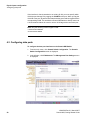
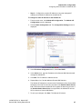
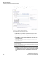
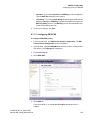
To generate the software license key:
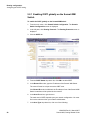
1. Login on the CLS. The Login screen is displayed.
If the content on the Login screen is in German, select English from the View
site in drop-down menu in the left pane.
2. In the right pane, click Generate and Download License Keys. A list of
licenses registered in your company’s name is displayed.
3. Select the Summit Switch WM-Series WLAN Switch Software version for
which you want to generate the license key.
To view the software features, click the + node against the Summit Switch
WM-Series WLAN Switch Software.
44
120385-00 Rev 01, March 2007
Summit WM, Getting Started Guide
HWC_GSG_Chapter 2_Default_Settings.fm
Summit WM-Series WLAN Switch configuration
Generating a software license key
4. Click Generate Key. The License Generation Key Details screen is
displayed.
5. In the MAC Address and Serial Number text boxes, type the MAC address
and the serial number of the hardware.
120385-00 Rev 01, March 2007
Summit WM, Getting Started Guide
45
HWC_GSG_Chapter 2_Default_Settings.fm
Summit WM-Series WLAN Switch configuration
Generating a software license key
6. In the Regulatory Domain drop-down list, click the regulatory domain.
7. Click Verify. The system verifies your inputs.
If the system returns any error, you must resolve the error before proceeding.
8. Click Next. The License Generation Details screen is displayed.
9. Click Next. A legal notice is displayed.
10. Select I agree with the above terms, and then click Finish. The
Transaction Information screen is displayed.
11. Click License Key(s). The License Key Details screen is displayed.
12. In the License Key (s) section, click Download. The File Download window
is displayed.
13. To save the file, click Save. The Save As window is displayed.
14. Save the file on your local drive.
Now that you have generated a software license key, you must apply this key to
the hardware (Summit WM Switch). For more information, see Section 3.6,
“Applying a license key”.
46
120385-00 Rev 01, March 2007
Summit WM, Getting Started Guide
HWC_GSG_Chapter 2_Default_Settings.fm
Summit WM-Series WLAN Switch configuration
Applying a license key
3.5.1 Retrieving a lost license key
If for some reason your license key (file) is corrupted or lost, you can retrieve a
lost license key through the CLS. The following sub-section describes how to
retrieve a lost license key.
To retrieve a lost license key:
1. Login on the CLS. The License Management screen is displayed.
2. In the left menu, click View Used Licenses. A list of used licenses is
displayed.
3. Locate the lost license in the list.
4. Select the applicable radio button for the product.
5. Click View Details. The License Key Details are displayed.
6. In the License Key (s) section, click Download. The File Download window
is displayed.
7. To save the file, click Save. The Save As window is displayed.
8. Save the file on your local drive.
3.6 Applying a license key
To apply the license:
1. Login on the Summit Switch.
2. From the main menu, click Summit Switch Configuration. The Summit
Switch Configuration screen is displayed.
3. In the left pane, click Software Maintenance.
120385-00 Rev 01, March 2007
Summit WM, Getting Started Guide
47
HWC_GSG_Chapter 2_Default_Settings.fm
Summit WM-Series WLAN Switch configuration
Applying a license key
4. Click the SWM Product Keys tab.
5. In the Apply Product Key section, click Browse to navigate to the location
of the software license file, and select the file.
6. Click Apply Now. The software license key is applied, and the Summit Switch
reboots.
Now you must configure the Summit WM Switch’s physical ports. The following
chapter describes how to configure the Summit WM Switch’s physical ports.
48
120385-00 Rev 01, March 2007
Summit WM, Getting Started Guide
HWC_GSG_PhysicalPortConfiguration..fm
Physical ports configuration
Physical data ports overview
4 Physical ports configuration
This chapter describes how to configure the Summit WM Switch’s physical ports.
The topics in this chapter are organized as follows:
•
Physical data ports overview
•
Configuring data ports
4.1 Physical data ports overview
Port configuration defines the administrative state of each interface. By default,
the data interface states are disabled. You must enable each of the data
interfaces individually. A disabled interface does not allow data to flow (receive/
transmit).
You can define the data ports to function as one of the following three types:
•
Host Port – You must use a Host Port definition to connect the Access Points
with dynamic routing disabled. The dynamic routing is disabled to ensure that
the port does not participate in dynamic routing operations to advertise the
availability of virtual network segments (WM-AD) hosted by the SWM. Host
ports may still be used as the target for static route definitions.
•
Third-party AP Port – You must use a Third-party AP Port definition for a
port to which you will be connecting the third-party APs. The third-party APs
must be deployed within a segregated network for which the Summit WM
Switch becomes the single point of access to the network. When you define
a port as the third-party AP port, the interface segregates the third-party AP
from the remaining network. Only one port can be configured for the thirdparty APs.
•
Router Port – You must use a Router Port definition for a port that you will
be connecting to an upstream, next-hop router in the network. When you
define a port as the router port, the system knows that the particular interface
is eligible to participate in dynamic routing protocol exchanges. The Summit
WM Switch supports OSPF as the dynamic routing protocol.
The Summit WM Switch is shipped from the factory with all of its data ports setup as host ports. You must set-up or configure how each port should function.
120385-00 Rev 01, March 2007
Summit WM, Getting Started Guide
49
HWC_GSG_PhysicalPortConfiguration..fm
Physical ports configuration
Configuring data ports
If the interface is directly attached to an existing VLAN, you must specify which
VLAN the port belongs to by tagging the VLAN ID to the port. When you tag the
VLAN ID to the port, all packets associated with the port would be tagged with the
corresponding VLAN. This enables the Summit WM Switch to directly connect to
a VLAN network without the need to remove VLAN tags at the connection port.
Note: Only the following models support VLAN:
• Summit Switch WM2000
• Summit Switch WM200
4.2 Configuring data ports
To configure the data port interfaces on the Summit WM Switch:
1. From the main menu, click Summit Switch Configuration. The Summit
Switch Configuration screen is displayed.
2. In the left pane, click IP Addresses. The Management Port Settings screen
is displayed.
50
120385-00 Rev 01, March 2007
Summit WM, Getting Started Guide
HWC_GSG_PhysicalPortConfiguration..fm
Physical ports configuration
Configuring data ports
The lower part of the screen displays the four ethernet ports, and each MAC
address is displayed under the MAC column. The lowest part of the screen
displays the text boxes for IP address, MAC address, Subnet mask and MTU.
You can edit these values.
Note: The number of ports displayed on the Management Port Settings screen (on
the GUI) reflects the number of physical ports the Summit WM Switch has. For
example, the Summit Switches, WM2000, WM 200, and WM100 have four data ports,
and hence the Management Port Settings screen will display four ports. The Summit
Switch WM1000has two data ports, and therefore the Management Port Settings
screen will display two ports
3. To enable the port, select the checkbox under the Enable column.
Note: You must disable all the interfaces that are not in use in order to avoid routing
loops.
4. Type the following:
•
IP address – The IP address of the physical ethernet port.
•
Subnet mask – The subnet mask for the IP address, which separates the
network portion from the host portion of the address (typically
255.255.255.0)
•
MTU – The maximum transmission unit or maximum packet size for this
port. The default setting is 1500. If you change this setting, and are using
OSPF, you must make sure that the MTU of each port in the OSPF link
matches.
Note: The Summit WM Switch and Altitude AP are capable of participating in MTU
discovery. During the MTU discovery process, the Summit WM Switch and Altitude AP
automatically learn the correct MTU, and then correct their settings accordingly. If the
routed connection to an Altitude AP travels a link that imposes a lower MTU than the
configured MTU, the Summit WM Switch and Altitude AP will correct their MTU
settings
5. From the Function drop-down list, click one of the three functions.
•
Host Port – Specifies a port for connecting Altitude APs with no dynamic
routing.
•
Third-party AP Port – Specifies a port to which the third-party AP is
connected.
•
Router Port – Specifies a port that connects to an upstream, next-hop
router in the network.
6. To enable management traffic on the port, select the Mgmt checkbox.
120385-00 Rev 01, March 2007
Summit WM, Getting Started Guide
51
HWC_GSG_PhysicalPortConfiguration..fm
Physical ports configuration
Configuring data ports
Enabling management provides access to the Summit Switch through the
selected port using SNMP (”get” only), SSH and HTTPS management
services.
7. To enable the SLP protocol, select the SLP checkbox.
Selecting the SLP checkbox will enable the Summit WM Switch to advertise
this port to the network for Altitude APs’ discovery.
8. Select either of the two VLAN options:
•
Untagged: Select Untagged, if you are not using VLAN.
•
Tagged: Select Tagged, and specify the VLAN ID in the VLANID text
box, if you are using VLAN.
Note: The VLAN text boxes on the Management Port Settings screen are displayed
only if you are using one of the following models:
• Summit Switch WM2000
• Summit Switch WM200
9. To allow multicast support, click Enabled from the drop-down list.
When you enable the multicast support, the interface is used for relaying
multicast traffic between core and wireless devices. You must define only one
port for the multicast traffic.
10. To save your changes, click Save.
11. Repeat Step 3 to Step 10 for every port that is to be enabled.
Now you must configure the routing on the Summit WM Switch. The following
chapter describes how to configure the Summit WM Switch’s physical ports.
52
120385-00 Rev 01, March 2007
Summit WM, Getting Started Guide
HWC_GSG_RouterConfiguration.fm
Routing configuration
Configuring static routing
5 Routing configuration
This chapter explains how to configure static routing and OSPF routing on the
Summit WM Switch.
The topics in this chapter are organized as follows:
•
Configuring static routing
•
Configuring the OSPF routing
5.1 Configuring static routing
To configure a static route:
1. From the main menu, click Summit Switch Configuration. The Summit
Switch Configuration screen is displayed.
2. In the left pane, click Routing Protocols. The Routing Protocols screen is
displayed.
3. To add a new route, type the destination IP address of a packet in the
Destination Address text box.
120385-00 Rev 01, March 2007
Summit WM, Getting Started Guide
53
HWC_GSG_RouterConfiguration.fm
Routing configuration
Configuring static routing
To define a default static route for any unknown address not in the routing
table, type 0.0.0.0. This is also called as defining the default gateway.
4. Type the appropriate subnet mask in the Subnet Mask text box to separate
the network portion from the host portion of the IP address (typically
255.255.255.0).
To define a default static route for any unknown address, type 0.0.0.0.
5. Type the IP address of the specific router port or gateway that serves as the
next-hop for the packets from Summit WM Switch (default gateway).
This router port (or gateway) must be on the same subnet as the Summit WM
Switch.
6. Click Add. The new route is added to the list of routes.
7. Select the Override dynamic routes check box to give priority over the
OSPF routes that the Summit WM Switch uses for routing.
By default, the Override dynamic routes is enabled. If you want to remove
priority for static routes so that the routing is always controlled dynamically,
clear the Override dynamic routes check box.
8. To save your changes, click Save.
5.1.1 Viewing the forwarding table
You can view the defined routes, whether static or OSPF, and their current status
in the forwarding table.
To view the forwarding table:
1. From the main menu, click Reports & Displays. The Reports & Displays
screen is displayed.
54
120385-00 Rev 01, March 2007
Summit WM, Getting Started Guide
HWC_GSG_RouterConfiguration.fm
Routing configuration
Configuring the OSPF routing
2. Click Forwarding Table. The Forwarding Table is displayed.
3. To update the display, click Refresh.
5.2 Configuring the OSPF routing
To configure the OSPF routing, you must:
•
Define one data port as a router port on the IP addresses screen.
•
Enable OSPF globally on the Summit WM Switch. For more information, see
Section 5.2.1, “Enabling OSPF globally on the Summit WM Switch”, on page
56.
•
Define the global OSPF parameters. For more information, see Section 5.2.2,
“Defining the global OSPF parameters”, on page 57.
Ensure that the OSPF parameters defined for the Summit WM Switch are
consistent with the adjacent routers in the OSPF area. The consistency
includes the following:
120385-00 Rev 01, March 2007
Summit WM, Getting Started Guide
•
Timer Settings – If the peer router has different timer settings, the protocol
timer settings in the Summit WM Switch must be changed to the peer
router to match in order to achieve OSPF adjacency.
•
MTU – The MTU of the ports on either sides of the OSPF link must match.
You must remember here that the MTU for ports is set to 1500 on the
Summit WM Switch is when configuring the physical data ports on IP
addresses’ screen. The value of 1500 matches the MTU in standard
routers.
55
HWC_GSG_RouterConfiguration.fm
Routing configuration
Configuring the OSPF routing
5.2.1 Enabling OSPF globally on the Summit WM
Switch
To enable the OSPF globally on the Summit WM Switch:
1. From the main menu, click Summit Switch Configuration. The Summit
Switch Configuration screen is displayed.
2. In the left pane, click Routing Protocols. The Routing Protocols screen is
displayed.
3. Click the OSPF tab.
4. From the OSPF Status drop-down list, click ON to enable OSPF.
5. In the Router ID text box, type the IP address of the Summit WM Switch.
The router ID must be unique across the OSPF area.
If the Router ID text box is left blank, the IP address of one of the Summit WM
Switch’s interfaces will be picked as the router ID.
6. In the Area ID text box, type the area.
The main area in OSPF depends upon your network configuration. You must
find out the main area from your network administrator.
7. In the Area Type drop-down list, click one of the following:
56
120385-00 Rev 01, March 2007
Summit WM, Getting Started Guide
HWC_GSG_RouterConfiguration.fm
Routing configuration
Configuring the OSPF routing
•
Default – Acts as the backbone area (also known as area zero). It forms
the core of an OSPF network. All other areas are connected to it, and
inter-area routing occurs via a router connected to the backbone area.
•
Stub – Does not receive external routes. External routes are defined as
routes, which are distributed in OSPF via another routing protocol.
Therefore, the Stub area relies on a default route to send traffic routes
outside the present domain.
•
Not-so-stubby – A type of stub area that can import autonomous system
(AS) external routes and send them to the default/backbone area, but can
not receive AS external routes from the backbone or other areas.
8. To save your changes, click Save.
5.2.2 Defining the global OSPF parameters
To define the global OSPF parameters:
1. From the main menu, click Summit Switch Configuration. The Summit
Switch Configuration screen is displayed.
2. In the left pane, click Routing Protocols. The Routing Protocols screen is
displayed.
3. Click the OSPF tab.
4. From the Port Status drop-down list, click Enabled. The OSPF is enabled on
the port.
Note: Only the interfaces defined as router type are available for OSPF neighborhood
establishment.
5. In the Link Cost text box, type the OSPF standard for your network for this
port.
The Link Cost is the cost of sending a data packet on the interface. The lower
the cost, the more likely the interface will be used to forward the data traffic.
Note: If more than one port is enabled for OSPF, you must prevent the Summit WM
Switch from serving as a router for the other traffic. In order to do this, you must set
the Link Cost to its maximum value of 65535.
6. From the Authentication drop-down list, click the authentication type of
OSPF on your network:
•
120385-00 Rev 01, March 2007
Summit WM, Getting Started Guide
None: The default is None. If None is selected, leave the Password text
box blank.
57
HWC_GSG_RouterConfiguration.fm
Routing configuration
Configuring the OSPF routing
•
Password: If Password is selected, type the password in the Password
text box in the.
7. Type the values in the following text boxes.
•
Hello-Interval – Specifies the time in seconds (displays OSPF default).
The default setting is 10.
•
Dead-Interval – Specifies the time in seconds (displays OSPF default).
The default setting is 40.
•
Retransmit-Interval – Specifies the time in seconds (displays OSPF
default). The default setting is 5.
•
Transmit Delay – Specifies the time in seconds (displays OSPF default).
The default setting is 1.
8. To save your changes, click Save.
Now you must confirm that the ports are set for OSPF.
5.2.2.1 Confirming the ports are set for OSPF
To confirm the ports are set for OSPF:
1. From the main menu, click Summit Switch Configuration. The Summit
Switch Configuration screen is displayed.
2. On the Routing Protocols screen, click View Forwarding Table. The
Forwarding Table is displayed.
3. Click the OSPF Neighbor tab.
If OSPF protocol is enabled, this report displays the current neighbors for
OSPF.
58
120385-00 Rev 01, March 2007
Summit WM, Getting Started Guide
HWC_GSG_RouterConfiguration.fm
Routing configuration
Configuring the OSPF routing
4. Click the OSPF Linkstate tab.
If OSPF protocol is enabled, the report displays the link state advertisement
(LSAs) received by the running OSPF protocol.
5. To update the screen, click Refresh.
Now you must configure the DHCP, DNS and RADIUS servers on the network.
The following chapter explains how to configure DHCP, DNS and IAS services on
Windows 2003 Server.
120385-00 Rev 01, March 2007
Summit WM, Getting Started Guide
59
HWC_GSG_RouterConfiguration.fm
Routing configuration
Configuring the OSPF routing
60
120385-00 Rev 01, March 2007
Summit WM, Getting Started Guide
HWC_GSG_ConfiguringExternalServers.fm
Configuring DHCP, DNS and IAS services
DHCP service configuration
6 Configuring DHCP, DNS and IAS services
This chapter describes how to configure DHCP, DNS and IAS services on
Windows 2003 Server. In addition, the chapter explains how to configure DHCP
service on a Linux-based server.
Note that your Windows 2003 or Linux server may have a different configuration
process than what is described here. You must refer to your manufacturer’s
document to know the configuration process that is specific to your server.
The configuration processes described in this chapter should be used as
examples.
The topics in this chapter are organized as follows:
•
DHCP service configuration
•
IAS service configuration
•
DNS service configuration
6.1 DHCP service configuration
Before you can configure the DHCP service, you must install it on the server.
DHCP is not installed by default during a typical installation of Windows Standard
Server 2003 or Windows Enterprise Server 2003. You can install DHCP either
during the initial installation of Windows Server 2003 or after the initial installation
is completed.
You must also install 078 SLP DA Option. The 078 SLP DA Option is not
installed by default during a typical installation of DHCP service.
You may visit http://support.microsoft.com to learn how to install DHCP and 078
SLP DA Option on Windows 2003.
The following section describes how to configure DHCP for Summit WM-Series
WLAN Switch Software Solution.
6.1.1 Configuring DHCP in Windows 2003 Server
You must also enable 078 SLP DA Option for every scope you define. A scope
is a collection of IP addresses meant to be distributed by the DHCP server to the
client devices on a subnet.
The SLP DA is used by:
• The Altitude APs to discover the Summit WM Switch.
• The mobility agents to discover the mobility manager.
120385-00 Rev 01, March 2007
Summit WM, Getting Started Guide
61
HWC_GSG_ConfiguringExternalServers.fm
Configuring DHCP, DNS and IAS services
DHCP service configuration
To configure DHCP in Window 2003 Server:
1. Click Start, point to Administrative Tool, and then click DHCP.
2. In the console tree, right-click the DHCP server on which you want to create
the new DHCP scope, and then click New Scope.
3. Click Next. The Scope Name window is displayed.
4. In the Name and Description text boxes, type the scope’s name and the
description respectively.
This can be any name that you want, but it should be descriptive enough so
that you can identify the purpose of the scope on your network.
5. Click Next. The IP Address Range window is displayed.
6. In the Start IP address and the End IP address text boxes, type the start and
end of the IP addresses’ range that you want to be distributed to the network.
Range – Is the range of addresses that the scope will distribute across the
network. You must use the range provided by your network administrator.
7. In the Length text box, type the numeric value of the subnet mask’s bits; or
in the Subnet mask text box, type the subnet mask’s IP address.
62
120385-00 Rev 01, March 2007
Summit WM, Getting Started Guide
HWC_GSG_ConfiguringExternalServers.fm
Configuring DHCP, DNS and IAS services
DHCP service configuration
A subnet mask defines how many bits of an IP address to use for the network/
subnet IDs and how many bits to use for the host ID. You can specify the
subnet mask by length or as an IP address. You must use the Length (or the
Subnet mask) provided by your network administrator.
8. Click Next. The Add Exclusions window is displayed.
9. In the Start IP address and the End IP address text boxes, type the start and
end of the IP addresses’ range that you want to exclude from the distribution.
You must use the exclusion range provided by your network administrator.
10. Click Next. The Lease Duration window is displayed.
The DHCP server assigns a client an IP address for a given amount of time.
The amount of time for which the IP address can be leased is defined in the
Lease Duration window.
11. In the Days, Hours and Minutes text box, type the lease duration.
You must use the Lease Duration as specified by your network administrator.
12. Click Next. The Configure DHCP Options window is displayed.
13. Select Yes, I want to configure these options now, and then click Next.
The Router (Default Gateway) window is displayed.
14. In the IP address text box, type the network’s default gateway.
You must use the default gateway provided by your network administrator.
120385-00 Rev 01, March 2007
Summit WM, Getting Started Guide
63
HWC_GSG_ConfiguringExternalServers.fm
Configuring DHCP, DNS and IAS services
DHCP service configuration
15. Click Next. The Domain Name and DNS Servers window is displayed.
16. In the Parent domain text box, type your company’s domain name.
You must use the Parent Domain provided by your network administrator.
17. In the Server name text box, type your server name.
You must use the Server name provided by your network administrator.
18. In the IP address text box, type your server’s IP address, and click Add.
19. Click Next. The WINS Servers window is displayed.
20. Click Next. The Activate Scope window is displayed.
21. Select Yes, I want to activate this scope now, and click Next. The wizard
displays the following message: This server is now a DHCP server.
22. Click Start, point to Administrative Tool, and then click DHCP. The DHCP
console tree is displayed.
23. Select the scope you configured, and right-click.
24. Select Configure Options. The Server Options window is displayed.
25. Enable 078 SLP DA.
64
120385-00 Rev 01, March 2007
Summit WM, Getting Started Guide
HWC_GSG_ConfiguringExternalServers.fm
Configuring DHCP, DNS and IAS services
DHCP service configuration
26. In the lower pane of the screen, type the hexadecimal values of the SLP DA’s
IP address.
Note:
• The Altitude APs use the SLP DA to discover the Summit WM Switch.
• The mobility agents use the SLP DA to discover the mobility manager.
Note: here is no SLP deployment on the enterprise network, the Summit WM Switch
is configured to act as a DA by default. If you put the Summit WM Switch’s IP
address(es) in a DHCP server for Option 78, Altitude APs will interact with the Summit
WM Switch for discovery.
Similarly, the mobility agents will also interact with the Summit WM Switch to discover
the mobility manager.
27. Click Apply, and then click OK.
6.1.2 Configuring DHCP in Red Hat Linux Server
You can configure a DHCP server using the configuration file /etc/
dhcpd.conf.
DHCP also uses the file /var/lib/dhcp/dhcpd.leases to store the client
lease database.
The first step in configuring a DHCP server is to create the configuration file that
stores the network information for the clients. Global options can be declared for
all clients, or options can be declared for each client system.
The configuration file can contain any extra tabs or blank lines for easier
formatting. The keywords are not case-sensitive and lines beginning with a hash
mark (#) are considered comments.
To use the recommended mode, add the following line to the top of the
configuration file:
ddns-update-style interim;
Read the dhcpd.conf man page for details about the different modes.
There are two types of statements in the configuration file:
•
Parameters – State how to perform a task, whether to perform a task or what
networking configuration options to use to send to the client.
•
Declarations – Describe the topology of the network, describe the clients,
provide addresses for the clients, or apply a group of parameters to a group
of declarations.
120385-00 Rev 01, March 2007
Summit WM, Getting Started Guide
65
HWC_GSG_ConfiguringExternalServers.fm
Configuring DHCP, DNS and IAS services
DHCP service configuration
Some parameters must start with the option keyword and are referred to as
options. Options configure DHCP options; whereas, parameters configure values
that are not optional or control how the DHCP server behaves.
Parameters (including options) declared before a section enclosed in curly
brackets {} are considered global parameters. Global parameters apply to all the
sections below it.
Note: If you change the configuration file, the changes will not take effect until you restart
the DHCP daemon with the command service dhcpd restart.
The following is the example of DHCP configuration on a Red Hat Linux Server.
For Altitude AP subnet
subnet 10.209.0.0 netmask 255.255.255.0 {
option routers 10.209.0.2; ### This is the network’s default
gateway address.
option subnet-mask 255.255.255.0
option domain-name xyznetworks.ca
option domain-name servers 192.168.1.3, 207.236, 176.11
range 10.209.0.3 10.209.0.40;
default-lease-time 7200000 ###The figures are in seconds.
option slp-directory-agent true 10.209.0.1, 10.209.0.3;
####The Altitude APs use the SLP DA to discover the Summit WM
Switch, and the mobility agents use it to discover the mobility manager.
authoritative;
For WM-AD subnets (In Summit WM Switch it is configured as Use DHCP
Relay)
if you are utilizing multiple WM-ADs you must configure the Red Hat Linux server
for every WM-AD.
The following is the example of DHCP configuration in Red Hat Linux for two WMADs (For more information, see Chapter 8, “WM-AD configuration”).
66
120385-00 Rev 01, March 2007
Summit WM, Getting Started Guide
HWC_GSG_ConfiguringExternalServers.fm
Configuring DHCP, DNS and IAS services
IAS service configuration
subnet 172.29.31.0 netmask 255.255.255.224
option routers 172.29.31.1; #### This is the WM-AD 1 gateway.
option subnet-mask 255. 255. 255.0
option domain-name toronto.xyznetworks.com”;
option domain-name-servers 192.1.1.3;
range 172.29.31.2 172.29.31.30;
default-lease-time 36000;
max-lease-time 7200000;###The figures are in seconds.
authoritative;
}
subnet 172.29.2.0 netmask 255.255.255.224
option routers 172.29.2.1; #### This is the WM-AD 2 gateway.
option subnet-mask 255. 255. 255.0
option domain-name toronto.xyznetworks.com”;
option domain-name-servers 192.1.1.3;
range 172.29.2.2 172.29.2.30;
default-lease-time 36000;
max-lease-time 7200000;###The figures are in seconds.
authoritative;
}
6.2 IAS service configuration
Microsoft Internet Authentication Service (IAS) can run as a Remote
Authentication Dial-in User Service (RADIUS) server. You can use IAS for
centralized authentication and accounting of multiple client devices.
IAS configuration involves the following steps:
•
Step 1 – Installing IAS on Windows 2003 Server
•
Step 2 – Enabling IAS to authenticate users in active directory
•
Step 3 – Configuring IAS properties
•
Step 4 – Configuring Summit WM Switch as IAS client
•
Step 5– Configuring Remote Access Policies
120385-00 Rev 01, March 2007
Summit WM, Getting Started Guide
67
HWC_GSG_ConfiguringExternalServers.fm
Configuring DHCP, DNS and IAS services
IAS service configuration
6.2.1 Installing IAS on Windows 2003 Server
You must install IAS on Windows 2003 Server according to the documentation
provided with the server. You may also visit http://support.microsoft.com to learn
how to install IAS on Windows 2003.
6.2.2 Enabling IAS to authenticate users in active
directory
To enable IAS to authenticate users in active directory:
1. Click Start, point to Programs, point to Administrative Tools, and then click
Internet Authentication Service.
2. In the Action menu, click Register Service in Active Directory.
3. To confirm the IAS registration in the local domain, click OK.
6.2.3 Configuring IAS properties
To configure the IAS properties:
1. Click Start, point to Programs, point to Administrative Tools, and then click
Internet Authentication Service.
2. Right-click Internet Authentication Service (Local), and then click
Properties.
3. In the Description text box, type a name that you want to assign to this IAS
server.
4. If you do not want to record the rejected authentication requests, clear the
Log rejected or discarded authentication requests checkbox.
Note: You can use the log file to determine if unauthorized users are attempting to
authenticate themselves in the domain.
5. If you do not want to record the successful authentication requests, clear the
Log successful authentication requests checkbox.
Note: You can use the log file to determine the usage patterns of wireless users.
6. Click the Ports tab.
68
120385-00 Rev 01, March 2007
Summit WM, Getting Started Guide
HWC_GSG_ConfiguringExternalServers.fm
Configuring DHCP, DNS and IAS services
IAS service configuration
7. In the Authentication text box, type the Summit WM Switch’s port # that is
used to access the authentication (IAS) service.
8. In the Accounting text box, type the Summit WM Switch’s port # that is used
to access the accounting service.
You must note that the values you type in the Authentication text box should
match the value that you define in the Port text box of Auth section on the
Auth & Acct tab of Summit WM Switch’s WM-AD screen. For more
information, see Section 8.5, “Configuring authentication mechanism for WMAD” of Chapter 8, “WM-AD configuration”.
120385-00 Rev 01, March 2007
Summit WM, Getting Started Guide
69
HWC_GSG_ConfiguringExternalServers.fm
Configuring DHCP, DNS and IAS services
IAS service configuration
Similarly, the values you type in the Accounting text box, should match the
value that you define in the Port text box of Acct section in the Acc & Acct
tab of Summit WM Switch’s WM-AD screen.For more information, see
Section 8.5, “Configuring authentication mechanism for WM-AD” of Chapter
8, “WM-AD configuration”.
70
120385-00 Rev 01, March 2007
Summit WM, Getting Started Guide
HWC_GSG_ConfiguringExternalServers.fm
Configuring DHCP, DNS and IAS services
IAS service configuration
6.2.4 Configuring Summit WM Switch as IAS client
To configure Summit WM Switch as IAS client:
1. Click Start, point to Administrative Tool, and then click Internet
Authentication Service.
2. Right-click Clients, and then New Client.
3. In the Friendly name text box, type the name that you want to assign to the
Summit WM Switch, and then click Next.
4. In the Client address (IP or DNS) text box, type the IP address of the Summit
WM Switch, and then click Verify.
5. Click Resolve. If the IP address is correct, it appears in the Search results
text box.
6. Click Use this IP.
7. In the Client-Vendor list, click RADIUS Standard.
120385-00 Rev 01, March 2007
Summit WM, Getting Started Guide
71
HWC_GSG_ConfiguringExternalServers.fm
Configuring DHCP, DNS and IAS services
IAS service configuration
8. In the Shared secret text box, type a password that both the IAS server and
the Summit WM Switch will use to mutually authenticate.
Note: This password is case-sensitive. You can use alphanumeric characters as well
as special characters. The password must be between 16 and 24 characters in length.
You must configure the shared secret password in Summit WM Switch. For more
information, see Section 8.5.1.2, “Configuring external Captive Portal authentication”,
on page 108.
9. Retype the password in the Confirm shared secret box, and then click
Finish.
6.2.5 Configuring Remote Access Policies
To configure Remote Access Policy:
1. Click Start, point to Administrative Tool, and then click Internet
Authentication Service.
2. Click Remote Access Policies.
3. In the right pane of the Internet Authentication Service, click Allow access
if dial-in permission is enabled, and then right-click Allow access if dialin permission is enabled.
4. Click Delete. A dialogue box is displayed.
5. Click Yes on the dialogue box.
6. On the Action menu, click New Remote Access Policy. The New Remote
Access Policy Wizard is displayed.
72
120385-00 Rev 01, March 2007
Summit WM, Getting Started Guide
HWC_GSG_ConfiguringExternalServers.fm
Configuring DHCP, DNS and IAS services
IAS service configuration
7. Click Next. The Policy Configuration Method window is displayed.
120385-00 Rev 01, March 2007
Summit WM, Getting Started Guide
73
HWC_GSG_ConfiguringExternalServers.fm
Configuring DHCP, DNS and IAS services
IAS service configuration
8. Select Use the wizard to set up a typical policy for a common scenario.
9. In the Policy name text box, type the name you want to assign to the policy,
and then click Next. The Access Method window is displayed.
74
120385-00 Rev 01, March 2007
Summit WM, Getting Started Guide
HWC_GSG_ConfiguringExternalServers.fm
Configuring DHCP, DNS and IAS services
IAS service configuration
10. Select Wireless and then click Next. The User or Group Access window is
displayed.
11. Select User or Group, and click Next. The Authentication Methods window
is displayed.
120385-00 Rev 01, March 2007
Summit WM, Getting Started Guide
75
HWC_GSG_ConfiguringExternalServers.fm
Configuring DHCP, DNS and IAS services
DNS service configuration
12. Select Protected EAP (PEAP) or Smart card or other certificate, and click
Next.
13. Click Finish. The new policy is displayed in the right pane.
14. In the right pane, select and right-click the newly configured remote access
policy.
15. Select Properties. The Properties window is displayed.
16. Select Grant Remote Access Permission.
17. Click Apply and then click OK.
18. Click Add. The Attributes window is displayed.
19. Select IP address. The Client IP-Address window is displayed.
20. In the Client IP-Address window, type the Summit WM Switch’s IP address.
21. Click OK.
6.3 DNS service configuration
The domain name system (DNS) stores and associates many types of
information with domain names, but most importantly, it translates domain names
(computer hostnames) to IP addresses.
You must install DNS on Windows 2003 Server according to the documents
provided with the server. Visit http://support.microsoft.com to learn how to install
DNS on Windows 2003.
The DNS configuration involves two steps:
76
•
Step 1 – Configuring the DNS for internet access
•
Step 2 – Configuring DNS for Altitude APs discovery.
120385-00 Rev 01, March 2007
Summit WM, Getting Started Guide
HWC_GSG_ConfiguringExternalServers.fm
Configuring DHCP, DNS and IAS services
DNS service configuration
6.3.1 Configuring DNS for internet access
To configure DNS for internet access:
1. Click Start, point to All Programs, point to Administrative Tools, and then
click Configure Your Server Wizard.
2. Click Next. The Summary of Selections window is displayed.
Note: The Summary of Selections window should list the following two items: Install
DNS and Run the Configure a DNS Wizard to configure DNS.
If the Summary of Selections window does not list these two items, you must:
• Click Back to return to DNS Server Roles window.
• Click DNS.
• Click Next.
3. In the Summary of Selections window, click Next. The Select
Configuration Action window is displayed.
When the Configure Your Server wizard installs the DNS service, it first
determines whether the IP address for this server is static or the server is
configured to secure it automatically.
If your server is currently configured to obtain its IP address, the wizard
prompts you to configure the server with a static IP address instead of
displaying the Select Configuration Action window.
To configure the server with a static IP address:
a) In the Local Area Connection Properties, click Internet Protocol (TCP/
IP), and then click Properties. The Internet Protocol (TCP/IP)
Properties window is displayed.
b) In the Internet Protocol (TCP/IP) Properties window, click Use the
following IP address.
c) In the Static IP address, Subnet mask, and the Default gateway text
boxes, type the static IP address, the subnet mask and the IP address of
the default gateway respectively.
d) In the Preferred DNS text box, type the IP address of the server.
e) In the Alternate DNS text box, type the IP address of another internal
DNS server.
The Alternate DNS text box is optional.
f)
Click OK, and then click Close.
4. In the Select Configuration Action window, select the Create a forward
lookup zone checkbox, and then click Next. The Primary Server Location
window is displayed.
120385-00 Rev 01, March 2007
Summit WM, Getting Started Guide
77
HWC_GSG_ConfiguringExternalServers.fm
Configuring DHCP, DNS and IAS services
DNS service configuration
5. In the Primary Server Location window, select This server maintains the
zone, and then click Next. The Zone name window is displayed.
6. In the Zone name text box, type the name of the DNS zone for your
network, and then click Next. The Dynamic Update window is displayed.
The zone name is identical to the DNS domain for small organization or
branch office.
7. In the Dynamic Update window, click Allow both nonsecure and secure
dynamic updates, and then click Next. The Forwarders window is
displayed.
8. In the Forwarders window, click Yes, it should forward queries to DNS
servers with the following IP addresses.
When you select this feature, all DNS queries for DNS names are forwarded
to a DNS at either your ISP or central office.
9. In the IP addresses text box, type one or more IP addresses that either your
ISP or central office DNS servers use, and click Next.
10. Click Finish. The wizard displays the following message: This server is Now
a DNS Server.
6.3.2 Configuring DNS for Altitude APs discovery
To configure DNS for Altitude APs discovery:
1. Click Start, point to All Programs, point to Administrative Tools, and then
click DNS.
2. Select the domain.
3. In the Action menu, select New Domain. The New DNS Domain window is
displayed.
4. In the New DNS Domain window, type the name for the new domain.
5. Restart the service. The new domain is displayed as the child domain.
78
120385-00 Rev 01, March 2007
Summit WM, Getting Started Guide
HWC_GSG_ConfiguringExternalServers.fm
Configuring DHCP, DNS and IAS services
DNS service configuration
6. Right-click the new domain name, and select New Host. The New Host
window is displayed.
7. In the Name text box, type the Summit WM Switch’s name.
8. In the IP address text box, type the Summit WM Switch’s IP address.
9. Select Create associated pointer (PTR) record checkbox.
10. Click Add Host. The new host is displayed in the right pane of the screen.
11. Quit DNS.
Now you must configure the Altitude APs via the Summit WM Switch.
120385-00 Rev 01, March 2007
Summit WM, Getting Started Guide
79
HWC_GSG_ConfiguringExternalServers.fm
Configuring DHCP, DNS and IAS services
DNS service configuration
80
120385-00 Rev 01, March 2007
Summit WM, Getting Started Guide
HWC_GSG_APConfiguration.fm
Altitude AP’s configuration
Altitude AP overview
7 Altitude AP’s configuration
This chapter describes how to configure and manage the Altitude APs.
The topics in this chapter are organized as follows:
•
Altitude AP overview
•
Configuring the Altitude APs for the first time
•
Assigning names to Altitude APs
•
Modifying Altitude APs’ properties
•
Configuring static IP address for Altitude APs
•
Configuring VLAN tags for Altitude APs
•
Altitude AP’s LED states
7.1 Altitude AP overview
Altitude APs bridge network traffic between wireless devices and the Ethernet
LAN.
The Altitude APs, by default, do not have a graphical user interface (GUI); they
are configured and managed by the Extreme Networks Summit WM-Series
Console. In addition, you can centrally manage (verify and upgrade) the Altitude
AP firmware image via the Extreme Networks Summit WM-Series Console.
All communication with the Summit WM Switch is carried out using a UDP-based
protocol. The protocol encapsulates the IP traffic from the Altitude AP and directs
it to the Summit WM Switch. The Summit WM Switch decapsulates the packets
and routes them to the appropriate destinations while managing sessions and
applying policy.
The Altitude APs are available in two models:
•
Altitude AP 350-2 – Integrated Antenna Access Point
•
Altitude AP 350-2 – Detachable Antenna Access Point
The Altitude APs have two radios:
•
2.4 GHz radio supporting the 802.11b/g standards
•
5 GHz radio supporting the 802.11a standard
The radios on the Altitude APs are enabled or disabled through the Extreme
Networks Summit WM-Series Console. For more information, see the Chapter 5
– Configuring the Altitude AP of Summit WM-Series WLAN Switch Software
WM2000 User Guide.
120385-00 Rev 01, March 2007
Summit WM, Getting Started Guide
81
HWC_GSG_APConfiguration.fm
Altitude AP’s configuration
Configuring the Altitude APs for the first time
7.2 Configuring the Altitude APs for the first time
Before you start configuring the Altitude APs, ensure that you have:
•
Set-up, installed and configured the Summit WM Switch.
•
Installed the Altitude APs at the location indicated by your site survey.
To configure the Altitude APs for the first time:
1. From the main menu, click Altitude AP Configuration. The Altitude AP
screen is displayed.
2. In the left pane, click WAP Registration.
3. In the Security Mode section, select one of the following options:
Note: Security mode is a Summit WM Switch property. It defines how the Summit WM
Switch behaves when registering new devices. During the registration process, the
Summit WM Switch’s approval of the Altitude APs depends on the security mode that
has been set.
•
Allow all WAPs to connect:
•
82
If the Summit WM Switch does not recognize the registering serial
number, a new registration record is automatically created for the
Altitude AP. The Altitude AP receives a default configuration.
120385-00 Rev 01, March 2007
Summit WM, Getting Started Guide
HWC_GSG_APConfiguration.fm
Altitude AP’s configuration
Configuring the Altitude APs for the first time
•
•
If the Summit WM Switch recognizes the serial number, it indicates
that the registering device is pre-registered with the Summit WM
Switch. The Summit WM Switch uses the existing registration record,
and existing configuration record to authenticate and configure the
Altitude AP respectively.
Allow only approved Altitude APs to connect:
•
If the Summit WM Switch does not recognize the Altitude AP, the
Altitude AP’s registration record is created in pending state. You must
manually approve a pending Altitude AP. As long as the Altitude AP
is in pending state, it receives minimum configuration that only allows
it to maintain an active link with the Summit WM Switch for future state
change. For more information, see Section 7.2.1, “Manually
approving pending Altitude APs”.
•
If the Summit WM Switch recognizes the serial number, it uses the
existing registration record to authenticate the Altitude AP. Following
the successful authentication, the Altitude AP is configured according
to its stored configuration record.
4. In the Discovery Timers section, type the discovery timer values in the
following text boxes:
•
Number of retries – Limited to 255 in a five minute discovery period. The
default value is 2.
•
Default between retries – The default value is 1 second.
5. To save your changes, click Save.
6. To initiate the discovery and registration process, connect the Altitude AP to
a power source.
The Altitude APs can be connected and powered in the following ways:
•
•
Power over Ethernet (802.3af):
•
PoE enabled with port
•
PoE Injector
Power by AC adaptor
For more information, see the Altitude AP Installation Guide.
120385-00 Rev 01, March 2007
Summit WM, Getting Started Guide
83
HWC_GSG_APConfiguration.fm
Altitude AP’s configuration
Configuring the Altitude APs for the first time
7.2.1 Manually approving pending Altitude APs
If the Summit WM Switch does not recognize the Altitude AP, the Altitude AP’s
registration record is created in pending state. You must manually approve a
pending Altitude AP. As long as the Altitude AP is in pending state, it receives
minimum configuration that only allows it to maintain an active link with the
Summit WM Switch for future state change.
To manually approve pending Altitude APs:
1. From the main menu, click Altitude AP Configuration. The Altitude AP
screen is displayed
2. In the left pane, click Access Approval. The Access Approval screen is
displayed.
3. In the Select Altitude APs section, click Pending. The pending Altitude APs
are selected.
4. In the Perform action on selected Altitude APs, click Approved. The state
of the selected Altitude APs is changed from “Pending” to “Approved”.
84
120385-00 Rev 01, March 2007
Summit WM, Getting Started Guide
HWC_GSG_APConfiguration.fm
Altitude AP’s configuration
Assigning names to Altitude APs
7.3 Assigning names to Altitude APs
After the Altitude APs are successfully registered, you can assign them
appropriate names.
To assign a name to a Altitude AP:
1. From the main menu, click Altitude AP Configuration. The Altitude AP
screen is displayed.
2. In the Altitude AP list, click the Altitude AP for which you want to assign a
name. The WAP Properties tab is displayed.
3. In the Name text box, type the name that you want to assign to the selected
Altitude AP.
4. To save your changes, click Save.
Note: You can modify the Altitude AP’s properties that are displayed in the right pane
of the Altitude AP screen. For more information, see Section 7.4, “Modifying Altitude
APs’ properties”.
7.4 Modifying Altitude APs’ properties
After the Altitude APs are successfully registered, you can modify their properties.
To assign a name to a Altitude AP:
1. From the main menu, click Altitude AP Configuration. The Altitude AP
screen is displayed.
2. In the Altitude AP list, click the Altitude AP for which you want to modify the
properties. The WAP Properties tab is displayed.
The WAP Properties displays the following properties:
120385-00 Rev 01, March 2007
Summit WM, Getting Started Guide
•
Name – By default, this text box contains the serial number of the Altitude
AP.
•
Description – Short description of the Altitude AP.
•
Port # – Summit WM Switch’s ethernet port to which the Altitude AP is
connected.
•
Poll Timeout – The timeout value for polling the Summit WM Switch. The
value is in seconds. The default value is 10 seconds.
•
Poll Interval – The time interval during which the polling will occur. The
value is in seconds. The default value is two seconds.
85
HWC_GSG_APConfiguration.fm
Altitude AP’s configuration
Configuring static IP address for Altitude APs
•
Telnet Access – A feature you must select if the Telnet access to the
Altitude AP is enabled, or deselect if the Telnet access to the Altitude AP
is disabled.
•
Maintain client session in event of poll failure – Select this option, if
you want the Altitude AP to remain active in case the link with the Summit
WM Switch is lost. This allows service for the branch WM-ADs to continue
during temporary network outages.
•
User Broadcast for disassociation – If you want the Altitude AP to use
broadcast disassociation when disconnecting all wireless devices instead
of disassociating each client one by one, you must select this feature.
This feature is disabled by default.
•
Country – Where the Altitude AP operates.
3. To save your changes, click Save.
The following properties are view only on the WAP Properties tab:
•
Serial # – A unique identifier that is assigned during the manufacturing
process of the Altitude APs.
•
Hardware Version – The current version of the Altitude AP hardware.
•
Application Version – The current version of the Altitude AP software.
•
Status – The Altitude AP state:
•
•
Approved – Indicates that the Altitude AP has received its binding
key from the Summit WM Switch in the discovery process.
•
Pending – Indicates that the Altitude AP has not been approved as
yet to access the Summit WM Switch. Pending Altitude APs will not
provide service to client devices until they are approved.
Active Clients – The number of wireless devices that are currently active
on the Altitude AP.
4. Modify other properties according to your needs.
5. To save your changes, click Save.
7.5 Configuring static IP address for Altitude APs
Altitude AP static configuration can be used in both central office and branch
office deployments. In order to ensure that the static IP configuration is done
correctly, you must use the DHCP initially to obtain an IP address for the Altitude
AP. Then use these values in the static IP address configuration.
•
86
Step 1 – Use the DHCP Server to acquire the IP address
120385-00 Rev 01, March 2007
Summit WM, Getting Started Guide
HWC_GSG_APConfiguration.fm
Altitude AP’s configuration
Configuring static IP address for Altitude APs
•
Step 2 – Configure the acquired IP address (or any other assigned IP
address) as the Static IP address for the Altitude AP.
To configure a static IP address for the Altitude AP:
1. From the main menu, click Altitude AP Configuration. The Altitude AP
Configuration screen is displayed.
2. Click the Static Configuration tab. The Configuration Settings screen is
displayed.
3. In the IP Address Assignment section, select Use DHCP.
4. In the Add text box, type the IP address of the Summit WM Switch that will
manage this Altitude AP.
5. Click Add. The IP address is added to the list.
6. Repeat Steps 4 to 5 to add additional Summit WM Switches.
The Altitude AP attempts to connect to the IP addresses (of the Summit WM
Switches) in the order in which they are listed in the Summit Switch Search
List. This feature allows the Altitude AP to bypass the discovery process. If
the Summit Switch Search List is not populated, the Altitude AP will use
SLP to discover a Summit WM Switch.
7. To save your changes, click Save. The Altitude AP reboots.
120385-00 Rev 01, March 2007
Summit WM, Getting Started Guide
87
HWC_GSG_APConfiguration.fm
Altitude AP’s configuration
Configuring static IP address for Altitude APs
8. From the main menu, click Reports & Displays. The Reports and Displays
screen is displayed.
9. Click Active Altitude APs. A list of active Altitude APs is displayed with the
corresponding IP addresses assigned to them by the DHCP server.
88
120385-00 Rev 01, March 2007
Summit WM, Getting Started Guide
HWC_GSG_APConfiguration.fm
Altitude AP’s configuration
Configuring static IP address for Altitude APs
10. Locate the Altitude AP for which you are configuring the static IP address in
the list, and the corresponding IP address.
11. From the main menu, click Altitude AP Configuration. The Altitude AP
screen is displayed.
120385-00 Rev 01, March 2007
Summit WM, Getting Started Guide
89
HWC_GSG_APConfiguration.fm
Altitude AP’s configuration
Configuring static IP address for Altitude APs
12. Click the Static Configuration tab.
13. In the IP Address Assignment section, select Static Values.
14. In the IP Address text box, type the IP address that you obtained by using
the DHCP server (or any other assigned IP address).
15. In the Netmask text box, type the appropriate subnet mask to separate the
network portion from the host portion of the address.
16. In the Gateway text box, type the default gateway of the network.
17. To save your changes, click Save. The Altitude AP reboots.
90
120385-00 Rev 01, March 2007
Summit WM, Getting Started Guide
HWC_GSG_APConfiguration.fm
Altitude AP’s configuration
Configuring VLAN tags for Altitude APs
7.6 Configuring VLAN tags for Altitude APs
You must exercise caution while configuring VLAN ID tag. If a VLAN tag is not
configured properly, the connectivity between the Summit WM Switch and the
Altitude AP will be lost.
Note: To configure the VLAN tag for Altitude AP, you must connect the Altitude AP to
a point on the central office network that does not require VLAN tagging. If the VLAN
tagging is configured correctly and you are still on the central office network, the
Altitude AP will lose connection with the Summit WM Switch after it is rebooted (the
Altitude AP reboots when the configuration settings are saved). If the Altitude AP does
not lose connection with the Summit WM Switch after the reboot, it indicates that the
VLAN ID has not been configured correctly. This provides a feedback on whether you
have configured the VLAN tag correctly. After the VLAN is configured correctly, you
can move the Altitude AP to the target location.
To configure Altitude APs with a VLAN tag:
1. Connect the Altitude AP in the central office to the Summit WM Switch port
(or to a network point) that does not require VLAN tagging.
2. In the VLAN Settings section, select Tagged - VLAN ID.
3. In the Tagged - VLAN ID text box, type the VLAN ID on which the Altitude AP
will operate.
4. To save your changes, click Save. The Altitude AP reboots and loses
connection with the Summit WM Switch.
5. Log out from the Summit WM Switch.
6. Disconnect the Altitude AP from the central office network and move it to the
target location.
7. Power the Altitude AP. The Altitude AP connects to the Summit WM Switch.
If the Altitude AP does not connect to the Summit WM Switch, it implies that
the Altitude AP was not configured properly. To recover from this situation,
you must reset the Altitude AP to its factory default settings, and reconfigure
the static IP address. For more information, see Section 7.6.1, “Resetting the
Altitude AP to its factory default settings”, on page 92.
120385-00 Rev 01, March 2007
Summit WM, Getting Started Guide
91
HWC_GSG_APConfiguration.fm
Altitude AP’s configuration
Configuring VLAN tags for Altitude APs
7.6.1 Resetting the Altitude AP to its factory default
settings
You can reset the Altitude AP to its factory default settings if the Altitude APs
incorrectly configured.
The Altitude AP boot-up sequence includes a random delay interval, followed by
a vulnerable time interval. During the vulnerable time interval (2 seconds), the
LEDs flash in a particular sequence to indicate that the Summit WM Switch is in
the vulnerable time interval. For more information, see Section 7.7, “Altitude AP’s
LED states”, on page 93.
If you power up the Altitude AP and interrupt the power during the vulnerable time
interval three consecutive times, the fourth time the Altitude AP reboots, it will
restore its factory defaults including the user password and the default IP settings.
To reset the Altitude AP to its factory default settings:
1. Reboot the Altitude AP.
2. Depower and repower the Altitude AP during the vulnerable time interval.
3. Repeat Step 2 two more times.
When the Altitude AP reboots for the fourth time, after having its power supply
interrupted three consecutive times, it restores its factory default settings. The
Altitude AP then reboots again to put the default settings into effect.
Reset button (Hardware)
You can also reset the Altitude AP to its factory default settings by pressing and
holding the Reset button on the Altitude AP for approximately five seconds. Not
all models of the Altitude APs have the Reset button
The following figure illustrates the location of the Reset button on the Altitude
APs.
Ethernet
AC/DC Power
Reset
Port
Supply
Button
92
120385-00 Rev 01, March 2007
Summit WM, Getting Started Guide
HWC_GSG_APConfiguration.fm
Altitude AP’s configuration
Altitude AP’s LED states
7.7 Altitude AP’s LED states
When the Altitude AP is powered on and boots, you can follow its progress
through the registration process by observing the LED sequence described
below.
The Status LED (center) also indicates power — unlit when unit is off, and green
(solid) when the Altitude AP has completed discovery and is operational.
Figure 12
Altitude AP LEDs
Left LED Status
Center LED Status
Right LED
Status
Altitude AP Status
Off
Off
Off
Powered-off
Off
Green
Off
Beginning of Power-on-Self-Test (POST) (0.5 seconds)
Off
Off
Off
Power-on-Self-Test (POST
Off
Red
Off
Failure during POST
Green
Off
Green
Random delay – State displayed only after a vulnerable reset
Green/Off
Off/Green
Green/Off
Vulnerable time interval – The Altitude AP resets to factory
default if powered-off for three consecutive times during this
state. No vulnerable period when Altitude AP is resetting to
factory defaults.
Green/Off/Off
Off/Green/Off
Off/Off/Green Resetting to factory defaults announcement – replaces
vulnerable period. This pattern is repeated twice to notify the
operator when the factory configuration is restored.
Off
Orange
(Green + Red)
Off
Attempting to obtain an IP address via DHCP.
Off
Red/Orange
Off
No DHCP reply has been received.
Off
Green/Orange
Off
Failed discovery (SLP)
Off
Off/Orange
Off
Summit WM Switch has been discovered. Registering the
Altitude AP.
Off
Off/Red
Off
Registration of the Altitude AP has failed.
Off
Off/Green
Off
Standby, registered with a Summit WM Switch, waiting for
configuration.
Table 5
Altitude AP LED status
120385-00 Rev 01, March 2007
Summit WM, Getting Started Guide
93
HWC_GSG_APConfiguration.fm
Altitude AP’s configuration
Altitude AP’s LED states
Left LED Status
Center LED Status
Right LED
Status
Green when
802.11 b/g
enabled.
Off otherwise.
Green
Green when Radios enabled per user settings.
802.11a
enabled.
Off otherwise
Off
Red/Green
Off
Table 5
Altitude AP Status
Upgrading firmware.
Altitude AP LED status
Note: Random delays do not occur during normal reboot. A random delay only occurs after
vulnerable period power-down.
Now you must configure the WM-AD via the Summit WM Switch using the
Extreme Networks Summit WM-Series Console. The following chapter explains
how to configure the WM-AD.
94
120385-00 Rev 01, March 2007
Summit WM, Getting Started Guide
HWC_GSG_VNSConfiguration.fm
WM-AD configuration
WM-AD topology overview
8 WM-AD configuration
This chapter explains how to configure the WM-AD through the Summit WM
Switch using the Extreme Networks Summit WM-Series Console.
The topics in this chapter are organized as follows:
•
WM-AD topology overview
•
Creating and configuring a Routed WM-AD
•
Creating and configuring a Bridge Traffic Locally At SWM WM-AD
•
Creating and configuring a Bridge Traffic Locally At WAP WM-AD
•
Configuring authentication mechanism for WM-AD
•
Configuring filtering rules
•
Configuring privacy for WM-AD
8.1 WM-AD topology overview
Summit WM-Series Switch Software provides a versatile means of mapping
wireless networks to the topology of an existing wired network. This is
accomplished through the assignment of WM Access Domain Services.
When you set up WM Access Domain Services (WM-AD) on the Summit WMSeries Switch, you are defining subnets for groups of wireless users. This WMAD definition creates a virtual IP subnet where the Summit WM-Series Switch
acts as a default gateway for wireless devices.
This technique enables policies and authentication to be applied to the groups of
wireless users on a WM-AD, as well as the collecting of accounting information
on user sessions that can be used for billing.
When a WM-AD is set up on the Summit WM-Series Switch:
•
One or more Altitude APs (by radio) are associated with it
•
A range of IP addresses is set aside for the Summit WM-Series Switch’s
DHCP server to assign to wireless devices
If routing protocol is enabled, the Summit WM-Series Switch advertises the WMAD as a routable network segment to the wired network, and routes traffic
between the wireless devices and the wired network.
Each radio on a Altitude AP can participate in up to four WM-ADs, via the multiSSID function.
The WM-AD topologies are classified on the basis of the following WM-AD types:
120385-00 Rev 01, March 2007
Summit WM, Getting Started Guide
95
HWC_GSG_VNSConfiguration.fm
WM-AD configuration
WM-AD topology overview
•
Routed WM-AD – The user traffic is tunneled to the Summit WM Switch. This
is the default set-up.
•
Bridge at the WAP WM-AD (Bridge Traffic Locally at WAP) – The user
traffic is directly bridged with VLAN at the AP’s point of access (switch port).
•
VLAN bridged WM-AD (Bridge Traffic Locally at SWM) – The user traffic
is tunneled to the Summit WM Switch and is directly bridged with it to a
specific VLAN.
Note: Only the following models support VLAN bridged WM-AD (Bridge Traffic Locally
at SWM):
• Summit Switch WM2000
• Summit Switch WM200
SSID and AAA determine the WM-AD’s network assignment. These network
assignments define a framework for carrying out the authentication of the mobile
devices.
Creating a new WM-AD involves the following three steps:
96
•
Assigning a name to the proposed WM-AD
•
Defining the topology parameters
•
Configuring the WM-AD for authentication and privacy
120385-00 Rev 01, March 2007
Summit WM, Getting Started Guide
HWC_GSG_VNSConfiguration.fm
WM-AD configuration
Creating and configuring a Routed WM-AD
8.2 Creating and configuring a Routed WM-AD
The user traffic is tunneled to the Summit WM Switch in Routed WM-AD type.
This is the default set-up.
To create and configure a Routed WM-AD type:
1. From the main menu, click WM Access Domain Configuration. The WM
Access Domain Configuration screen is displayed.
2. In the Add subnet text box, type the WM-AD name.
3. Click Add subnet. The name is displayed in the virtual networks list and the
Topology tab is displayed.
120385-00 Rev 01, March 2007
Summit WM, Getting Started Guide
97
HWC_GSG_VNSConfiguration.fm
WM-AD configuration
Creating and configuring a Routed WM-AD
4. From the WM-AD Mode drop-down list, click Routed.
5. From the DHCP drop-down list, click one of the two options:
•
98
Local DHCP Server: If you select Local DHCP Server, the built-in DHCP
server in Summit WM Switch provides the IP addresses to the devices to
the wireless network. For more information, see Section 2.1.5.2, “DHCP
for WM-AD”, on page 18.
•
Gateway – The Summit WM Switch advertises this address to the
wireless devices when they sign on and get a dynamic IP address.
The gateway corresponds to the IP address that is communicated to
mobile users
•
Mask – Subnet mask for this IP address to separate the network
portion from the host portion of the address (typically 255.255.255.0).
•
Address Range – Range from which the IP addresses are provided
to the wireless devices that would use this WM-AD. This text box
(from and to) may populate automatically, if you have already
provided the range while configuring the APs.
•
B’cast Address – Populates automatically based on the Gateway IP
address and the subnet mask of the WM-AD.
•
Domain Name – External enterprise domain name. You must type
the external enterprise domain name in this text box.
120385-00 Rev 01, March 2007
Summit WM, Getting Started Guide
HWC_GSG_VNSConfiguration.fm
WM-AD configuration
Creating and configuring a Routed WM-AD
•
•
Lease – text box has two sub text boxes – default, and maximum.
The two sub text boxes dictate the default and maximum time limits a
wireless device can keep the DHCP server-assigned IP address. The
default value for Lease default is 36000 seconds (10 hours), the
default value for Lease Max is 2539000 seconds.
•
DNS Server – This text box relates to the IP address of the domain
name server on the enterprise network.
Use DHCP Relay: If you select Use DHCP Relay, the local DHCP server
on the Summit WM Switch is disabled and the Summit WM Switch instead
forwards DHCP requests to the external DHCP server for dynamic IP
addresses allocation. For more information, see Section 2.1.5.3, “DHCP
relay for WM-AD”, on page 19
•
Gateway – For more information, see Step # 5 on page 98.
•
Mask – For more information, see Step # 5 on page 98.
•
DHCP Server – IP address of the external DHCP server on the
enterprise network.
6. From the Network Assignment drop-down list, select the network
assignment.
The Network Assignment drop-down list gives you two options – SSID and
AAA. To learn more about SSID and AAA, see Section 8.1, “WM-AD topology
overview”.
•
SSID network assignment:
•
Allow mgmt traffic – If the management traffic is enabled, it
overrides the built-in exception filters that prohibit traffic on the
Summit WM Switch data interfaces. For more information on filters,
see “Section 7.6 Configuring filtering rules for WM-AD” of Summit
WM-Series WLAN Switch Software, V4 WM2000 User Guide.
•
Allow 3rd Party AP – If Allow 3rd Party AP is enabled, it allows for
the specification of a segregated subnet for non-SWM Altitude APs
for providing RF services to the users while still utilizing the Summit
WM Switch for user authentication and the user policy enforcement.
The definition of third-party AP identification parameters allows the
system to be able to differentiate the third-party AP device (and the
corresponding traffic) from the user devices on that segment. Devices
identified as third-party APs are considered pre-authenticated and
are not required to complete the corresponding authentication
verification stages defined for the users in that segment.
7. Type the values in the following three Timeout text boxes:
•
120385-00 Rev 01, March 2007
Summit WM, Getting Started Guide
Idle (Pre) Timeout – Number of seconds a user is allowed to be idle on
the WM-AD before authentication.
99
HWC_GSG_VNSConfiguration.fm
WM-AD configuration
Creating and configuring a Bridge Traffic Locally At SWM WM-AD
•
Idle (Post) Timeout – Number of seconds a user is allowed to idle on the
WM-AD after authentication.
•
Session – Maximum amount of time a session is allowed on the system.
If you leave this text box blank, there will be no time limit.
8. Type the values in the Next Hop Routing text boxes.
•
Next Hop Address – The next-hop IP identifies the target device to which
all WM-AD (user traffic) will be forwarded to. Next-hop definition
supersedes any other possible definition in the routing table.
•
OSPF Route Cost – The OSPF cost value provides a relative cost
indication to allow upstream routers to calculate whether or not to use the
Summit WM Switch as a better fit, or lowest cost path to reach the devices
in a particular network. The higher the cost, the less likely that the Summit
WM Switch will be chosen as a route for traffic, unless that Summit WM
Switch is the only possible route for that traffic.
•
Disable OSPF Advertisement – To disable the OSPF advertisement on
the WM-AD select Disable OSPF Advertisement.
9. To save your changes, click Save.
As a next step, you must configure the authentication mechanism for the WM-AD.
For more information, see Section 8.5, “Configuring authentication mechanism
for WM-AD”.
8.3 Creating and configuring a Bridge Traffic Locally At SWM WM-AD
Note: Only the following models support Bridge Traffic Locally at SWM:
• Summit Switch WM2000
• Summit Switch WM200
To configure a bridge traffic locally at SWM WM-AD:
1. From the main menu, click WM Access Domain Configuration. The WM
Access Domain Configuration screen is displayed.
2. In the Add subnet text box, type the WM-AD name.
3. Click Add subnet. The name is displayed in the virtual networks list and the
Topology tab is displayed.
4. From the WM-AD Mode drop-down list, click Bridge Traffic Locally At
SWM. The following text boxes are displayed:
100
120385-00 Rev 01, March 2007
Summit WM, Getting Started Guide
HWC_GSG_VNSConfiguration.fm
WM-AD configuration
Creating and configuring a Bridge Traffic Locally At WAP WM-AD
•
DHCP Option – Provides you the option of either using the external
DHCP server or the local DHCP server on the Summit WM Switch. For
more information, see Step # 5 of Creating and configuring “Routed” WMAD.
•
VLAN ID – The ID #of VLAN that is mapped to a Summit WM Switch
interface.
•
Interface – The name of the interface to which the VLAN is mapped.
•
Interface IP address – The interface’s IP address.
•
Mask – The subnet mask of the WM-AD.
5. From the Network Assignment drop-down list, click the network
assignment. For more information on network assignment, see “Step # 6 of
Creating and configuring Routed WM-AD”.
6. Type the values in the following three Timeout text boxes – Idle (Pre), Idle
(Post), and Session. For more information on Timeout text boxes, see “Step
# 7 of Creating and configuring Routed WM-AD”.
7. To save your changes, click Save.
As a next step, you must configure the authentication mechanism for the WM-AD.
For more information, see Section 8.5, “Configuring authentication mechanism
for WM-AD”.
8.4 Creating and configuring a Bridge Traffic Locally At WAP WM-AD
This configuration enables the WM-AD to provide branch office mode. The VLAN
ID for the branch office is assigned by the office network administrator. The
Altitude AP will operate correctly only when the VLAN ID is unique per AP.
To configure a Bridge traffic locally at AP WM-AD:
1. From the main menu, click WM Access Domain Configuration. The WM
Access Domain Configuration screen is displayed.
2. In the Add subnet text box, located in the lower portion of the left pane, type
the WM-AD name.
3. Click Add subnet. The name is displayed in the virtual networks list and the
Topology tab is displayed.
4. From the WM-AD Mode drop-down list, click Bridge Traffic Locally At
APWAP. The VLAN Setting text boxes are displayed.
5. To define the VLAN setting, select one of the following:
•
120385-00 Rev 01, March 2007
Summit WM, Getting Started Guide
Tagged – If you select Tagged, type the VLAN ID in VLAN ID text box.
The default value is 1.
101
HWC_GSG_VNSConfiguration.fm
WM-AD configuration
Configuring authentication mechanism for WM-AD
•
Untagged – If you select Untagged, the VLAN will be untagged.
6. To save your changes, click Save.
You have created a WM-AD. Now you must configure the authentication
mechanism for the WM-AD.
The following section explains how to configure the authentication mechanism.
8.5 Configuring authentication mechanism for WM-AD
The Summit WM Switch offers several authentication options. The options can be
classified under network assignment types – SSID and AAA (Authentication,
Authorization and Accounting).
•
SSID – The SSID network assignment type offers the following authentication
options:
•
•
By Captive Portal
•
By internal Captive Portal
•
By external Captive Portal
•
No Captive Portal support
By MAC-based authentication
Note: You must note here that the internal Captive Portal does not substitute the
external RADIUS server. The RADIUS server is still needed. The internal Captive
Portal within the Summit WM Switch displays the webpage to enable the users to
supply their user name and password. The user name and password are sent to the
configured RADIUS server for authentication.
In case of external Captive Portal, webpage authentication is performed by the
external Captive Portal.
•
AAA – The AAA (Authentication, Authorization and Accounting) network
assignment type offers the following authentication options:
•
By 802.1x authentication – The mobile user is authenticated before
gaining access to the network.
•
By MAC-based authentication – The mobile user is authenticated on the
basis of their MAC address.
The following figure illustrates the authentication options:
102
120385-00 Rev 01, March 2007
Summit WM, Getting Started Guide
HWC_GSG_VNSConfiguration.fm
WM-AD configuration
Configuring authentication mechanism for WM-AD
Figure 13
Authentication options
MAC-based authentication can be used in both SSID network assignment and
AAA network type assignment.
8.5.1 Authentication mechanism for SSID network
assignment
The SSID network assignment provides the following authentication options:
•
•
120385-00 Rev 01, March 2007
Summit WM, Getting Started Guide
Captive Portal authentication.
•
Internal Captive Portal
•
External Captive Portal
•
No Captive Portal Support
MAC-based authentication
103
HWC_GSG_VNSConfiguration.fm
WM-AD configuration
Configuring authentication mechanism for WM-AD
8.5.1.1 Configuring internal Captive Portal authentication
In order to configure the authentication mechanism, you must first create and
configure a WM-AD. For more information, see the following:
•
Section 8.1, “WM-AD topology overview”
•
Section 8.2, “Creating and configuring a Routed WM-AD”;
•
Section 8.3, “Creating and configuring a Bridge Traffic Locally At SWM WMAD”.
To configure internal Captive Portal:
1. From the main menu, click WM Access Domain Configuration. The WM
Access Domain Configuration screen is displayed.
2. In the left pane, select the SSID WM-AD for which you want to configure the
authentication mechanism. The Topology tab is displayed.
3. Click the Auth & Acct tab. The Auth & Acct text boxes are displayed in the
right pane.
The Auth & Acct tab offers you the following thee options:
•
Auth – Defines the authentication servers.
•
MAC – Defines the servers for MAC-based authentication.
•
Acct – Defines the accounting servers.
4. Click Auth. The authentication text boxes are displayed.
5. From the RADIUS drop-down list, click the server that you want to use for
Captive Portal authentication. The selected server is displayed in the list of
Config’d Servers and a red asterisk is displayed next to Auth, indicating that
the server has been assigned.
Note: The RADIUS drop-down list reflects the servers that are defined on the Global
Settings screen. For more information, see the Summit WM-Series WLAN Switch
Software, V4 V4.0, WM2000 User Guide”.
Use the Up and Down buttons to prioritize the servers for redundancy. The
servers are prioritized in the sequence they are displayed in the list of
Config’d Servers. You can change the sequence by selecting the server and
then clicking on the Up and Down buttons.
6. Type the appropriate values in the Auth text boxes.
104
•
Port – Used to access the RADIUS server. The default is 1812.
•
# of Retries – Number of times the Summit WM Switch will attempt to
access the RADIUS server.
120385-00 Rev 01, March 2007
Summit WM, Getting Started Guide
HWC_GSG_VNSConfiguration.fm
WM-AD configuration
Configuring authentication mechanism for WM-AD
•
Timeout – Maximum time for which Summit WM Switch will wait for a
response from the RADIUS server before making a re-attempt.
•
NAS Identifier – RADIUS attribute that identifies the server responsible
for passing information to the designated servers and then acting on the
response returned. This is an optional text box.
•
Auth Type – Authentication protocol to be used by the RADIUS server to
authenticate the wireless device users. The four options are:
•
•
AP – Password authentication protocol
•
CHAP – Challenge handshake authentication protocol
•
MS-CHAP – Windows-specific version of CHAP
•
MS-CHAP v2– Windows-specific version of Chap (Version 2)
Set as primary server – Select to configure the RADIUS server as the
primary server.
7. Select the appropriate checkbox against Include VSA Attributes.
Vendor Specific Attributes feature provides you the following three options:
•
APs
•
WM-AD
•
SSID
These VSA are defined on the RADIUS server.
8. To reset the server that you are configuring as the primary server, click Reset
to Primary button is enabled and you want to reset the server (that you are
configuring) as the primary server, click Reset to Primary.
The Reset to Primary button is enabled in the following RADIUS redundancy
set-up scenarios:
•
The Summit WM Switch’s connection to the primary RADIUS server fails.
•
The Summit WM Switch automatically attempts and is successful in
initiating a connection with the alternative RADIUS server.
•
The alternative RADIUS server becomes the primary server.
If you want the server that you are configuring to be the primary server, you
must click on the enabled Reset to Primary button.
9. To save your changes, click Save.
10. Test the Summit WM Switch’s connection to all configured RADIUS servers.
To test the connection with the RADIUS servers, click Test. The RADIUS
servers display the message transaction on their screens. You must visually
verify the state of the server connection and the user authentication.
120385-00 Rev 01, March 2007
Summit WM, Getting Started Guide
105
HWC_GSG_VNSConfiguration.fm
WM-AD configuration
Configuring authentication mechanism for WM-AD
11. Click Configure Captive Portal Settings. The Captive Portal
Configurations screen is displayed.
12. Select the Internal Captive Portal option.
13. Type the values in the following text boxes:
•
Login Label – The text that will appear as a label for the user name.
•
Password Label –The text that will appear as a label for the user
password text box.
•
Header URL – The URL of the file to be displayed in the header of the
Captive Portal screen.
•
Footer URL – The URL of the file to be displayed in the footer of the
Captive Portal screen.
Note: The maximum width allowed for the header and footer is 790 pixels. There is no
restriction on the height.
If the width of the header/footer is more than 790 pixels, the header/footer will appear
truncated on the Captive Portal screen.
•
106
Message – The message that you type in this text box will appear above
the Login text box to greet the user. You can type a message explaining
why the Captive Portal screen is displayed and the instructions for the
user.
120385-00 Rev 01, March 2007
Summit WM, Getting Started Guide
HWC_GSG_VNSConfiguration.fm
WM-AD configuration
Configuring authentication mechanism for WM-AD
•
Replace Gateway IP with FQDN – If you are using FQDN (Fully
Qualified Domain Name) as the gateway address, you must type the
FQDN in this text box.
•
Default Redirection URL – The URL to which the wireless devices will
be directed before authentication.
•
Specific Message URL –
14. In the right pane, select the VSA (Vendor Specific Attributes) that you want to
send to the authentication server along with other authentication details for
authentication purpose.
•
AP Serial Number
•
AP Name
•
WM-AD Name
•
SSID
•
MAC Address
The selection of these VSAs dictate with what VSA the wireless users will be
identified. For example, the wireless users can be identified by which Altitude
AP or WM-AD they are using.
15. To provide the users with logoff button to signout, select Logoff.
If you select Logoff, the users will be provided with a logoff button to signout.
The logoff button launches a pop-up logoff screen, empowering the users to
control their logoff.
16. to provide the users with a status check button, select Status check.
The Status check button enables the users to monitor session statistics such
as system usage and time left in a session.
17. To save your changes, click Save.
18. To review your Captive Portal page, click View Sample Portal. The login
screen of the portal is displayed.
120385-00 Rev 01, March 2007
Summit WM, Getting Started Guide
107
HWC_GSG_VNSConfiguration.fm
WM-AD configuration
Configuring authentication mechanism for WM-AD
This display is the result of
what you entered in the
Header URL box.
This display is the result of
what you entered in the
Message box.
The display of Login and
Password is the result of
entries you made in Login
Label and Password boxes.
This display is the result of
what you entered in the
Footer URL box.
8.5.1.2 Configuring external Captive Portal authentication
In order to configure the authentication mechanism, you must first create and
configure a WM-AD. For more information, see the following.
•
Section 8.1, “WM-AD topology overview”
•
Section 8.2, “Creating and configuring a Routed WM-AD”
•
Section 8.3, “Creating and configuring a Bridge Traffic Locally At SWM WMAD”.
To configure external Captive Portal:
1. Configure internal captive portal authentication. For more information, see
Step 1 to Step 10 of Section 8.5.1.1, “Configuring internal Captive Portal
authentication”, on page 104.
2. Click Configure Captive Portal option. The Captive Portal Configuration
screen is displayed.
3. Select the External Captive Portal option.
4. In the SWM Connection drop-down list, click the Summit WM Switch’s IP
address.
5. In the Port text box, type the Summit WM Switch’s port.
108
120385-00 Rev 01, March 2007
Summit WM, Getting Started Guide
HWC_GSG_VNSConfiguration.fm
WM-AD configuration
Configuring authentication mechanism for WM-AD
6. In the Shared Secret text box, type the password for encrypting the
information exchanged between the Summit WM Switch and the external
Captive Portal server.
7. In the Redirection URL text box, type the URL to which the wireless user will
be directed before the authentication.
8. To save your changes, click Save.
8.5.1.3 No Captive Portal support
By default, a new WM-AD with SSID network assignment type is assigned None
authentication. A SSID WM-AD with this set-up circumvents all authentication
mechanisms and the Summit WM Switch accepts all wireless devices without any
authentication.
However, even with None authentication option, you can still control access to the
network by defining appropriate filtering rules for Non-authenticated filters. For
more information, see Section 8.6.1.2, “Configuring filtering rules for a Nonauthenticated filter”, on page 113.
None authentication does not mean that no authentication will take place.
Instead, the default filter is applied for the authentication. For more information,
see Section 8.5.1.3, “No Captive Portal support”, on page 109.
To configure None authentication:
1. From the main menu, click WM Access Domain Configuration. The WM
Access Domain Configuration screen is displayed.
2. In the left pane, select the SSID WM-AD for which you want to configure the
authentication mechanism. The Topology tab is displayed.
3. Click the Auth & Acct tab.
4. Click Configure Captive Portal. The Captive Portal Configuration screen
is displayed.
5. Select the No Captive Portal Support option.
6. To save your changes, click Save.
Note: In order to control network access of the wireless device users on this WM-AD,
you must define appropriate rules in Default filter.
The rules in the Default filter should be very restrictive when you use None
authentication mechanism.
You must configure the final rule in the Default filter a deny all rule.
For more information, see Section 8.6.1.3, “Configuring filtering rules for Default filter”,
on page 114.
120385-00 Rev 01, March 2007
Summit WM, Getting Started Guide
109
HWC_GSG_VNSConfiguration.fm
WM-AD configuration
Configuring authentication mechanism for WM-AD
8.5.1.4 Configuring MAC-based authentication
MAC-based authentication restricts wireless device’s access to the network,
based on its MAC addresses. The Summit WM Switch relays the client devices’
MAC address to a RADIUS server on your network following which the RADIUS
server checks the address against a list of allowed MAC addresses. If the client
device’s MAC address matches one in the list of allowed MAC addresses in the
RADIUS server, the user is granted access to the network.
To set-up the RADIUS server for MAC-based authentication, you must set-up a
user account with User ID=MAC and Password= MAC for each user.
To define MAC-based authentication for a WM-AD:
1. From the main menu, click WM Access Domain Configuration. The WM
Access Domain Configuration screen is displayed.
2. In the left pane, select the SSID WM-AD for which you want to configure the
authentication mechanism. The Topology tab is displayed.
3. Click the Auth & Acct tab.
4. Click MAC.
5. From the RADIUS drop-down list, click the server that you want to use for
MAC authentication.
6. Click Use. The selected server is displayed in the list of Config’d Servers
and a red asterisk is displayed next to MAC, indicating that the server has
been assigned.
Note: The RADIUS drop-down list reflects the servers that are defined on the Global
Settings screen. For more information, see “Summit WM-Series WLAN Switch
Software, V4, WM2000 User Guide”.
7. If your RADIUS server is being used for another type of authentication or
accounting, select Use server for MAC Authorization.
8. Type the values in the MAC text boxes.
110
•
Port – Port used to access the RADIUS server. The default is 1812.
•
# of Retries – Number of times the Summit WM Switch will attempt to
access the RADIUS server.
•
Timeout – Maximum time for which Summit WM Switch will wait for a
response from the RADIUS server before making a re-attempt.
•
NAS IP Address – IP address of the network access server (NAS).
•
NAS Identifier – RADIUS attribute that identifies the server responsible
for passing information to the designated servers. This is an optional text
box.
120385-00 Rev 01, March 2007
Summit WM, Getting Started Guide
HWC_GSG_VNSConfiguration.fm
WM-AD configuration
Configuring authentication mechanism for WM-AD
•
Auth Type – Provides four options for the authentication protocol to be
used by the RADIUS server to authenticate the wireless device users:
•
PAP – Password authentication protocol
•
CHAP – Challenge handshake authentication protocol
•
MS-CHAP – Windows-specific version of CHAP
•
MS-CHAP – Windows-specific version of Chap (Version 2)
•
Set as primary server – To set the RADIUS server as the primary server,
select Set as the primary server.
•
MAC-based authentication on roam check – To ensure that the client
devices are authorized every time they roam to another AP, select MACbased authentication on roam check. If you don’t select this feature,
the client devices will be authenticated only at the start of their sessions.
9. To save your changes, click Save.
8.5.2 Authentication mechanism for AAA network
assignment
The AAA (Authentication, Authorization and Accounting) network assignment
provides the following two authentication options:
•
802.1x authentication.
•
MAC-based authentication
The following sections explain the above two authentication options.
8.5.2.1 Configuring 802.1x authentication
For more information, see Section 8.7.2, “Configuring privacy for AAA network
assignment”, on page 118.
Note: Since Section 8.7.2, Privacy for AAA network assignment, is part of Privacy
policies configuration, you can configure 802.1x authentication after you
complete the configurations for authentication and filtering rules
120385-00 Rev 01, March 2007
Summit WM, Getting Started Guide
111
HWC_GSG_VNSConfiguration.fm
WM-AD configuration
Configuring filtering rules
8.5.2.2 Configuring MAC-based authentication
MAC-based authentication can be used in both SSID network assignment and
AAA network type assignment. For more information, see Section 8.5.1.4,
“Configuring MAC-based authentication”.
Now you must configure the WM-AD for filters. The following section describes
how to configure the WM-AD filters.
8.6 Configuring filtering rules
On a per WM-AD basis, the Summit WM Switch can be configured to apply a
specific filtering policy on the user traffic that is routed through it. The filtering
policies are applied after the authentication is returned.
The filter definition can be static on the Summit WM Switch itself, or the filter
definition can be set to dynamically provisioned if RADIUS authentication is used.
The standard RADIUS attribute can be used to identify a specific filter definition
to apply to incoming/outgoing user traffic upon successful authentication of the
user during authentication.
For more information, see Summit WM-Series WLAN Switch Software WM2000
User Guide.
8.6.1 Configuring filtering rules for filters in SSID
network assignment
The SSID network assignment type offers the following three default filters:
•
Exception
•
Non-authenticated
•
Default
8.6.1.1 Configuring filtering rules for Exception filter
To configure rules for the Exception filter:
1. From the main menu, click WM Access Domain Configuration. The WM
Access Domain Configuration screen is displayed.
2. In the left pane, click the SSID WM-AD for which you want to define the
filtering rules. The Topology tab is displayed.
3. Click the Filtering tab.
112
120385-00 Rev 01, March 2007
Summit WM, Getting Started Guide
HWC_GSG_VNSConfiguration.fm
WM-AD configuration
Configuring filtering rules
4. From the Filter ID drop-down list, click Exception.
5. Define a filtering rule.
a) In the IP/subnet:port text box, type the destination IP address.
You can also specify the IP range, a port designation or a port range on
the IP address in the IP/subnet:port text box.
b) From the Protocol drop-down list, click the applicable protocol.
The default is N/A.
c) Click Add. The filtering rule is displayed.
6. Define a rule to allow access to the default gateway for this WM-AD.
a) Select the IP:Port of the filtering rule that you defined in Step 5.
b) In the IP/subnet:port, type the default gateway IP address (WM-AD’s IP
address) that you defined in the Topology tab for this WM-AD.
c) Click Add. The rule is displayed.
7. Define more rules by carrying out Step 5 and Step 6.
8. Check the Allow feature for every rule you created.
You may edit the order of the rules by selecting a filter and clicking the Up/
Down buttons. The filtering rules are executed in the order that is displayed
on the screen.
9. To save your changes, click Save. The rules for the Exception filter are
saved.
8.6.1.2 Configuring filtering rules for a Non-authenticated filter
The rules for a Non-authenticated filter enable you to identify and manage the
destinations to which a mobile device is allowed to gain access without
undergoing an authentication redirection. Typically, the recommended default
rule is to deny all. Administrators must define the rules that will permit users to
access essential services such as the following:
•
DNS
•
Default Gateway (WM-AD interface IP)
Any HTTP streams requested by the client for denied targets will be redirected to
the specified location. For more information, see the Summit WM-Series WLAN
Switch Software WM2000 User Guide.
To configure rules for the Non-authenticated filter.
120385-00 Rev 01, March 2007
Summit WM, Getting Started Guide
113
HWC_GSG_VNSConfiguration.fm
WM-AD configuration
Configuring filtering rules
1. From the main menu, click WM Access Domain Configuration. The WM
Access Domain Configuration screen is displayed.
2. In the left pane, select the SSID WM-AD for which you want to configure the
Non-authenticated filtering rules. The Topology tab is displayed.
3. Click the Filtering tab.
4. From the Filter ID drop-down list, click Non-authenticated.
5. Define a filtering rule.
a) In the IP/subnet:port text box, type the destination IP address.
You can also specify the IP range, a port designation or a port range on
the IP address in the IP/subnet:port text box.
b) From the Protocol drop-down list, click the applicable protocol.
The default is N/A.
6. For Captive Portal assignment, define a rule to allow access to the default
gateway for this WM-AD
a) Select the IP:Port of the filtering rule that you defined in Step 5.
b) In the IP/subnet:port, type the default gateway IP address (WM-AD’s IP
address) that you defined in the Topology screen for this WM-AD.
7. Click Add. The rule is displayed in the middle of the screen.
8. If applicable, define more rules by repeating Steps 5 and 6.
9. To allow the traffic between the wireless device and the network, Select In
and Out.
10. Select the Allow feature for every rule you created.
11. To save your changes, click Save.
8.6.1.3 Configuring filtering rules for Default filter
The Default filter is applied by default (automatically) after the authentication of
the wireless device under the following circumstances:
•
No match is found in the Exception filter rules
•
No filter attribute value is returned by the authentication server for the device
•
No match is found in the filter ID values
In order to ensure that a packet is not dropped entirely under the above
circumstances, the final rule in the Default filter must be Allow All.
To configure rules for the Default filter:
114
120385-00 Rev 01, March 2007
Summit WM, Getting Started Guide
HWC_GSG_VNSConfiguration.fm
WM-AD configuration
Configuring privacy for WM-AD
1. From the main menu, click WM Access Domain Configuration. The WM
Access Domain Configuration screen is displayed.
2. In the left pane, click the WM-AD for which you want to configure the Default
filtering rules. The Topology tab is displayed.
3. Click the Filtering tab.
4. From the Filter ID drop-down list, click Default. The default rule in the Default
filter is displayed.
The default rule in the Default filter displays a Deny All configuration. You can
modify the configuration to Allow All, if it is appropriate for the network needs
of the WM-AD.
If applicable, you can create more rules for the Default filter.
5. Configure filtering rules for the Exception filter. For more information, see
Step 5 to Step 8 of Section 8.6.1.1, “Configuring filtering rules for Exception
filter”, on page 112.
6. To save your changes, click Save.
8.6.2 Configuring filtering rules for filters in AAA
network assignment
The AAA network assignment type offers the following two default filters:
•
Default
•
Exception
In AAA network assignment type, a Non-authenticated filter becomes
unnecessary because the users are already authenticated.
For more information, see Section 8.6.1.1, “Configuring filtering rules for
Exception filter”, on page 112, and Section 8.6.1.3, “Configuring filtering rules for
Default filter”, on page 114.
Now you must configure privacy for the WM-AD. The following section explains
how to configure privacy.
8.7 Configuring privacy for WM-AD
Privacy is a mechanism that protects data over wireless and wired networks using
encryption techniques.
The Summit WM Switch provides several privacy mechanism to protect data over
the WLAN. The privacy mechanism can be classified on the basis of network
assignment types — SSID and AAA.
120385-00 Rev 01, March 2007
Summit WM, Getting Started Guide
115
HWC_GSG_VNSConfiguration.fm
WM-AD configuration
Configuring privacy for WM-AD
8.7.1 Configuring privacy for SSID network
assignment
The SSID network assignment provides three privacy options:
•
None
•
Static WEP
•
WPA pre-shared key (PSK)
8.7.1.1 Configuring Static WEP
To configure Static WEP:
1. From the main menu, click WM Access Domain Configuration. The WM
Access Domain Configuration screen is displayed.
2. In the left pane, click the SSID WM-AD for which you want to configure the
Static WEP privacy. The topology tab is displayed.
3. Click the Privacy tab.
4. Select Static Keys (WEP).
5. Type the values in the following text boxes:
•
116
WEP Key Length – Size of a WEP Key.
120385-00 Rev 01, March 2007
Summit WM, Getting Started Guide
HWC_GSG_VNSConfiguration.fm
WM-AD configuration
Configuring privacy for WM-AD
•
Input Hex – If you enable Input Hex, the WEP Key text box is displayed.
Type the WEP Key manually in this text box.
•
Input String – If you select Input String, the following two text boxes are
displayed –Strings and WEP Key. Type the secret WEP Key string in the
WEP Key String text box. The WEP Key text box is automatically filled
by the corresponding Hex code.
6. To save your changes, click Save.
8.7.1.2 Configuring WPA-PSK
To configure WPA-PSK privacy:
1. From the main menu, click WM Access Domain Configuration. The WM
Access Domain Configuration screen is displayed.
2. In the left pane, click the SSID WM-AD for which you want to configure WPAPSK privacy. The Topology tab is displayed.
3. Click the Privacy tab.
4. Select WPA-PSK.
5. Select WPA v1.
If you select WPA v1, its subordinate Encryption drop-down menu is
enabled.
120385-00 Rev 01, March 2007
Summit WM, Getting Started Guide
117
HWC_GSG_VNSConfiguration.fm
WM-AD configuration
Configuring privacy for WM-AD
The Encryption drop-down menu offers you the following two options:
•
Auto – If you click Auto, the Altitude AP will advertise both TKIP and
CCMP (counter mode with cipher block chaining message
authentication code protocol).
•
TKIP only – If you click TKIP only, the Altitude AP will advertise TKIP
as an available encryption protocol. It will not advertise CCMP.
6. Select WPA v2.
If you select WPA v2, its subordinate Encryption drop-down menu is
enabled.
The Encryption drop-down menu offers you the following two options – Auto
and TKIP only. For more information, see Step # 5 on page 117.
7. To enable re-keying after a time interval, select Broadcast re-key interval.
If this feature is not selected, the broadcast encryption key is never changed
and the Altitude AP will always use the same broadcast key for broadcast/
multicast transmissions. This will compromise the security for wireless
communications.
8. In the Broadcast re-key interval text box, type the time interval after which
you want the broadcast encryption key to be changed automatically. The
default is 3600.
9. In the Pre-shared Key text box, type the shared secret key that is to be used
between the wireless device and the Altitude AP.
The shared secret key is used to generate the 256 bit key.
10. To confirm your entry, click Unmask. The shared key entry is displayed.
You must always unmask the shared secret key before you save your
settings.
11. To save your changes, click Save.
8.7.2 Configuring privacy for AAA network
assignment
The AAA (Authentication, Authorization and Accounting) assignment provides
following privacy mechanisms:
118
•
Static keys (WEP)
•
Dynamic WEP keys
•
Wi-fi Protected Access (WPA) version 1 with encryption by temporal key
integrity protocol (TKIP)
120385-00 Rev 01, March 2007
Summit WM, Getting Started Guide
HWC_GSG_VNSConfiguration.fm
WM-AD configuration
Configuring privacy for WM-AD
•
Wi-fi Protected Access (WPA) version 2 with encryption by advanced
encryption standard with counter-mode/CBC-MAC protocol (AES-CCMP)
8.7.2.1 Configuring Static WEP
To configure Static WEP:
1. From the main menu, click WM Access Domain Configuration. The WM
Access Domain Configuration screen is displayed.
2. In the left pane, click the AAA WM-AD for which you want to configure the
Static WEP privacy. The topology tab is displayed.
3. Click the Privacy tab.
4. Repeat Step 4 to Step 6 of Section 8.7.1.1, “Configuring Static WEP”, on page
116.
8.7.2.2 Configuring Dynamic WEP
The dynamic key WEP mechanism changes the key for each user and each
session.
To set up Dynamic WEP privacy:
1. From the main menu, click WM Access Domain Configuration. The WM
Access Domain Configuration screen is displayed.
2. In the left pane, click the AAA WM-AD for which you want to configure the
Dynamic WEP privacy. The Topology tab is displayed.
3. Click the Privacy tab.
4. Select Dynamic Keys.
5. To save your changes, click Save.
8.7.2.3 Configuring Wi-fi Protected Access (WPA v1 and WPA
v2) privacy
WPA v1 and WPA v2 adds authentication to WEP encryption and key
management. The authentication portion of WPA for AAA is in enterprise mode.
Key features of WPA privacy include:
•
Specifies 802.1x with extensible authentication protocol (EAP)
•
Uses RADIUS protocols for authentication and key distribution; therefore,
requires a RADIUS or other authentication server.
120385-00 Rev 01, March 2007
Summit WM, Getting Started Guide
119
HWC_GSG_VNSConfiguration.fm
WM-AD configuration
Configuring privacy for WM-AD
•
Centralizes management of user credentials.
The WPA authentication process involves the following steps:
•
Step 1 – The wireless device associates with Altitude AP.
•
Step 2 – The Altitude AP blocks the wireless device’s network access
while the authentication process is carried out. The Summit WM Switch
sends the authentication request to the RADIUS authentication server.
•
Step 3 – The wireless device provides credentials that are forwarded to
the authentication server through the Summit WM Switch.
•
Step 4 – If the wireless device is not authenticated, the device remains
blocked from the network.
For more information, see the Summit WM-Series WLAN Switch Software User
Guide.
To configure WPA privacy:
1. From the main menu, click WM Access Domain Configuration. The WM
Access Domain Configuration screen is displayed.
2. In the left pane, click the AAA WM-AD for which you want to configure the
Dynamic WEP privacy. The Topology tab is displayed.
3. Click the Privacy tab.
4. Select WPA. The WPA text boxes are displayed.
5. Select one of the following:
•
•
WPA v1:
•
Auto – If you click Auto, the Altitude AP will advertise both TKIP and
CCMP (counter mode with cipher block chaining message
authentication code protocol).
•
TKIP only – If you click TKIP only, the Altitude AP will advertise TKIP
as an available encryption protocol. It will not advertise CCMP.
WPA v2:
•
Auto: For more information, see the description of Auto under WPA
v1.
•
TKIP only: For more information, see the description of TKIP only
under WPA v1.
If you select WPA v1, its Encryption drop-down menu is enabled. The
Encryption drop-down menu offers the following two options:
6. For re-keying after a time interval, select Broadcast re-key interval.
120
120385-00 Rev 01, March 2007
Summit WM, Getting Started Guide
HWC_GSG_VNSConfiguration.fm
WM-AD configuration
Configuring privacy for WM-AD
If this feature is not enabled, the broadcast encryption key is never changed
and the Altitude AP will always use the same broadcast key for broadcast/
multicast transmissions. This will compromise the security for wireless
communications.
7. In the Broadcast re-key interval text box, type the time interval after which
you want the broadcast encryption key to be changed automatically. The
default is 3600.
8. To save your changes, click Save.
You have completed the WM-AD configuration.
Now you must configure the Summit WM Switch’s availability and mobility
features. The following chapter describes how to configure the Summit WM
Switch’s availability and mobility features.
120385-00 Rev 01, March 2007
Summit WM, Getting Started Guide
121
HWC_GSG_VNSConfiguration.fm
WM-AD configuration
Configuring privacy for WM-AD
122
120385-00 Rev 01, March 2007
Summit WM, Getting Started Guide
HWC_GSG_Avail&MobilConfiguration.fm
Availability and Mobility configuration
Availability overview
9 Availability and Mobility configuration
The chapter describes how to configure the Summit WM Switch’s availability and
mobility features.
The topics in this chapter are organized as follows:
•
Availability overview
•
Configuring availability feature
•
Mobility overview
•
Configuring mobility
9.1 Availability overview
The Summit WM-Series WLAN Switch Software solution’s availability feature
maintains service availability in the event of a Summit WM Switch outage.
The availability feature links two Summit WM Switches to form a pair in order to
share information about their Altitude APs. If one Summit WM Switch fails, its
Altitude APs are allowed to connect to the other Summit WM Switch.
The Altitude APs that connect to a backup Summit WM Switch during a failover
are assigned to the WM-AD that is defined in the Summit WM Switch’s default
Altitude AP configuration. If the default Altitude AP configuration does not exist
for the backup Summit WM Switch, the failover Altitude APs will not be assigned
to any WM-AD, and will therefore not provide service. Therefore it is very
important to define a default Altitude AP configuration on all Summit WM
Switches.
9.2 Configuring availability feature
Before you begin the availability configuration, you must ensure:
•
A network connection exists between the two Summit WM Switches. This
connection is used to enable the availability link between the Summit WM
Switches. The availability link is established on port 13907.
•
A DHCP server for the Altitude AP subnets is setup to support “Option 78 for
SLP”, so that it points to the IP addresses of the physical interfaces on both
the Summit WM Switches.
120385-00 Rev 01, March 2007
Summit WM, Getting Started Guide
123
HWC_GSG_Avail&MobilConfiguration.fm
Availability and Mobility configuration
Configuring availability feature
High-level overview of the availability configuration process
The following is a high-level overview of the availability configuration process:
•
Step 1 – Define a WM-AD with the same SSID on each Summit WM Switch.
For more information on how to define a WM-AD, see Chapter 8, “WM-AD
configuration”.
•
Step 2 – Associate radios and change poll timeout to 15 seconds in WM-AD
Assignment of Altitude AP default settings screen.
•
Step 3 – Assign the Altitude APs to their home Summit WM Switch.
•
Step 4 – Enable both the Summit WM Switches as an availability pair.
•
Step 5 – Define a primary Summit WM Switch.
•
Step 6 – Select one of the security mode options:
•
Allow all Altitude APs to connect – If the Summit WM Switch not
recognize the Altitude AP’s serial number, it sends a default configuration
to the Altitude AP. If the Summit WM Switch recognizes the serial number,
it sends the specific configuration (port and binding key) set to the Altitude
AP.
•
Allow only approved Altitude APs to connect – If the Summit WM
Switch does not recognize the Altitude AP’s serial number, it prompts you
to create a configuration. If the Summit WM Switch recognizes the serial
number, it sends the configuration (port and binding key) to the Altitude
AP.
This section is organized under the following sub-sections:
•
Defining a WM-AD with the same SSID on both the Summit WM Switches
•
Assigning radios to WM-AD, and changing the poll timeout value on Altitude
AP configuration screen
•
Assigning the Altitude APs to their home Summit WM Switch
•
Enabling availability pair, defining primary Summit WM Switch, and selecting
security mode
•
Viewing the Altitude AP availability display
•
Viewing the active Altitude APs report
9.2.1 Defining a WM-AD with the same SSID on both
the Summit WM Switches
Step 1of the availability configuration process is to define WM-AD with the same
SSID on both the Summit WM Switches
124
120385-00 Rev 01, March 2007
Summit WM, Getting Started Guide
HWC_GSG_Avail&MobilConfiguration.fm
Availability and Mobility configuration
Configuring availability feature
For information, see See Chapter 8, “WM-AD configuration”.
Note: You must use the same SSID on both the primary and the secondary
Summit WM Switches.
9.2.2 Assigning radios to WM-AD, and changing the
poll timeout value on Altitude AP configuration
screen
Step 2 of the availability configuration process is to assign radios to the WM-AD,
and changing the poll timeout value on Altitude AP configuration screen.
To assign radios to WM-AD and change the poll timeout value:
1. Login on both the Summit WM Switches.
2. From the main menu of the primary Summit WM Switch, click Altitude AP
Configuration. The Altitude A P Configuration screen is displayed.
3. In the left pane, click WAP Default Settings. The default settings are
displayed.
4. In the WAP Properties section, change the default value to 15 in the Poll
Timeout text box.
Note: The Poll Timeout value for availability must be 15.
5. In the WM-AD Assignment section, select the WM-AD that you have defined
for availability.
6. To assign b/g and a radios to the WM-AD, select the corresponding radio
checkboxes.
7. To save your changes, click Save.
8. From the main menu of the secondary Summit WM Switch, click Altitude AP
Configuration. The Altitude AP Configuration screen is displayed.
9. Repeat Step 3 to 7.
9.2.3 Assigning the Altitude APs to their home
Summit WM Switch
Step 3 of the availability configuration process is to assign the Altitude APs to their
home Summit WM Switch.
120385-00 Rev 01, March 2007
Summit WM, Getting Started Guide
125
HWC_GSG_Avail&MobilConfiguration.fm
Availability and Mobility configuration
Configuring availability feature
1. Login on both the Summit WM Switches.
2. From the main menu of the primary Summit WM Switch, click Altitude AP
Configuration. The Altitude AP Configuration screen is displayed.
3. In the left pane, click WAP. The WAP screen is displayed.
4. In the Registration Mode section, click Stand-alone.
5. In the Security Mode section, click Allow only approved Altitude APs to
connect.
6. From the main menu of the secondary Summit WM Switch, click Altitude AP
Configuration. The Altitude AP Configuration screen is displayed.
7. Repeat Step 3 to Step 5.
8. From the main menu of the primary Summit WM Switch, click Altitude AP
Configuration. The Altitude AP Configuration screen is displayed.
9. In the left menu, click Access Approval. The Access Approval screen is
displayed.
10. Check the status of every Altitude AP and approve all those that should be
connected to the primary Summit WM Switch.
Note: You must delete all such Altitude APs that are in pending state and you do not
intend to approve them.
126
120385-00 Rev 01, March 2007
Summit WM, Getting Started Guide
HWC_GSG_Avail&MobilConfiguration.fm
Availability and Mobility configuration
Configuring availability feature
11. From the main menu of the secondary Summit WM Switch, click Altitude AP
Configuration. The Altitude AP Configuration screen is displayed.
12. Repeat Step 9 to Step 10.
13. To save your changes, click Save.
Note: After you have assigned Altitude APs to their home Summit WM
Switch, you must check Active Altitude APs Report screen to ensure that
all those approved APs are indeed connected to their home Summit WM
Switch. For more information, see Section 9.2.6, “Viewing the active Altitude
APs report”, on page 129.
9.2.4 Enabling availability pair, defining primary
Summit WM Switch, and selecting security mode
Steps 4, 5 and 6 of the availability configuration process involve enabling
availability pair, defining primary Summit WM Switch, and selecting security
mode.
To enable the availability pair, define the primary Summit WM Switch, and
select the security mode:
1. Login on both the Summit WM Switches.
2. From the main menu of the primary Summit WM Switch, click Altitude AP
Registration. The Altitude AP Registration screen is displayed.
3. In the left pane, click WAP Registration. The WAP Registration screen is
displayed.
4. In the Registration mode section, click Paired.
5. From the main menu of the secondary Summit WM Switch, click Altitude AP
Configuration. The Altitude AP Configuration screen is displayed.
6. In the Registration mode section, click Paired.
7. From the main menu of the primary Summit WM Switch, click Altitude AP
Configuration.
8. In the Summit WM Switch IP Address text box, type the IP address of the
physical port of the secondary Summit WM Switch.
9. Select Current Summit Switch is primary connection point.
10. From the main menu of the secondary Summit WM Switch, click Altitude AP
Configuration. The Altitude AP Configuration is displayed.
120385-00 Rev 01, March 2007
Summit WM, Getting Started Guide
127
HWC_GSG_Avail&MobilConfiguration.fm
Availability and Mobility configuration
Configuring availability feature
11. In the Summit WM Switch IP Address, type the IP address of the
management port or physical port of the primary Summit WM Switch.
12. Clear the Current Summit Switch is primary connection point checkbox.
13. From the main menu of the primary Summit WM Switch, click Altitude AP
Configuration. The Altitude AP Configuration screen is displayed.
14. In the Security Mode, select one of the security mode options. For more
information, see page page 124.
15. To save your changes in the primary Summit WM Switch, click Save.
16. Open the Altitude AP Configuration of the secondary Summit WM Switch.
17. In the Security Mode, select one of the security mode options. For more
information, see page page 124.
18. To save your changes in the secondary Summit WM Switch, click Save.
9.2.5 Viewing the Altitude AP availability display
The Altitude AP availability display provides the active connection state of an
Altitude AP.
The display depicts the Altitude APs as color-coded boxes — Green and Red —
on the screen:
128
•
Green – The Altitude AP is configured on the Summit WM Switch and is
currently connected.
•
Red – The Altitude AP is configured on the Summit WM Switch but is currently
not connected (not available to service this Summit WM Switch).
120385-00 Rev 01, March 2007
Summit WM, Getting Started Guide
HWC_GSG_Avail&MobilConfiguration.fm
Availability and Mobility configuration
Configuring availability feature
To view the Altitude AP availability display:
1. From the main menu, click Reports & Display. The Reports & Displays
screen is displayed.
2. In the List of Displays, click Altitude AP Availability. The Altitude AP
Availability Display appears.
9.2.6 Viewing the active Altitude APs report
To view the active Altitude APs:
1. From the main menu, click Reports & Displays. The Reports & Display
screen is displayed.
2. In the List of Displays, click Active Altitude APs. The Active Altitude APs
display appears.
120385-00 Rev 01, March 2007
Summit WM, Getting Started Guide
129
HWC_GSG_Avail&MobilConfiguration.fm
Availability and Mobility configuration
Mobility overview
9.3 Mobility overview
The Summit WM-Series WLAN Switch Software Solution allows multiple Summit
WM Switches (up to 12) on a network to discover each other and exchange
information about a client session. This feature enables a wireless device user to
roam seamlessly between Altitude APs that are registered with separate Summit
WM Switches.
The solution introduces the concept of a mobility manager and mobility agents;
the concept requires designating one Summit WM Switch as the mobility
manager and other Summit WM Switches as mobility agents.
The wireless device keeps the IP address, WM-AD assignment, and filtering rules
it received from its home Summit WM Switch— the Summit WM Switch to which
it was first connected.
The WM-AD on each Summit WM Switch must have the same SSID and RF
privacy parameter settings for seamless roaming to occur.
The mobility manager and the mobility agents use the following two options for
the discovery process.
•
SLP with DHCP Option 78. The mobility agent on each Summit WM Switch
will discover the address of the mobility manager using Option 78.
•
Direct IP address option: Defined while configuring the mobility agent. By
explicitly defining the manager’s IP address while configuring the agents,
enables the manager and agents to find each other directly without using the
SLP discovery mechanisms.
Note: In order to provide tighter control of the registration steps for multi-domain
installations, direct IP address definition option is recommended.
The mobility manager:
•
130
Defines the registration behavior for a multi-Summit WM Switch mobility
domain set:
•
Open mode – A new agent automatically registers itself with the mobility
manager and immediately becomes part of the mobility domain.
•
Secure mode – The manager does not allow a new agent to automatically
register. Instead, the connection with the new agent is placed in pending
state until the administrator approves the connection.
•
Listens for connection attempts from mobility agents.
•
Establishes connection and sends a message to the mobility agent specifying
the heartbeat interval and the IP address in Mobility Permission List.
•
Sends regular Heartbeat messages containing wireless device session
changes and waits for a return update message.
120385-00 Rev 01, March 2007
Summit WM, Getting Started Guide
HWC_GSG_Avail&MobilConfiguration.fm
Availability and Mobility configuration
Configuring mobility
The agent:
•
Uses SLP or a statically configured IP address to locate the manager.
•
Uses the information from every heartbeat message received to update its
own tables and updates the manager with the information on the wireless
device users and data tunnels it is managing.
If a connection to a manager is lost:
•
Agent to agent connections still remain active, allowing seamless roaming to
continue.
•
The data link between the agents remains active after the loss of the
manager. The agents continue to use the last set of mobility location list to
service known users.
•
•
Existing users – Remain in mobility scenario and if the users are known
to mobility domain, they are able to continue roaming between the agents.
•
New users – Become local at the attaching agent. Roaming to another
agents resets the session.
Any user that roamed away from their home Altitude AP is terminated and
must reconnect, re-authenticate and obtain a new IP address.
9.4 Configuring mobility
To configure mobility feature, you must define one Summit WM Switch as the
mobility manager and other Summit WM Switches as mobility agents.
9.4.1 Configuring a Summit WM Switch as a mobility
manager
To configure Summit WM Switch as a mobility manager:
1. From the main menu, click Summit Switch Configuration. The Summit
Switch Configuration screen is displayed.
2. In the left pane, click Mobility Manager. The Mobility Manager Settings
screen is displayed.
120385-00 Rev 01, March 2007
Summit WM, Getting Started Guide
131
HWC_GSG_Avail&MobilConfiguration.fm
Availability and Mobility configuration
Configuring mobility
Note: The Mobility Manager link is not displayed in the left pane with the demo
license.
132
120385-00 Rev 01, March 2007
Summit WM, Getting Started Guide
HWC_GSG_Avail&MobilConfiguration.fm
Availability and Mobility configuration
Configuring mobility
3. To enable mobility for this Summit WM Switch, select the Enable Mobility
checkbox. The mobility options are displayed.
4. Select the This Summit Switch is a Mobility Manager option. The mobility
manager options are displayed.
5. In the Port drop-down list, click the interface of the Summit WM Switch that
is to be used as the mobility manager.
Ensure that the selected interface is routable on the network.
6. In the Heartbeat text box, type the time interval (in seconds) at which the
mobility manager sends a heartbeat message to the agent. The default is 5
seconds.
7. In the SLP Registration drop-down list, click one of the following:
120385-00 Rev 01, March 2007
Summit WM, Getting Started Guide
•
Enabled – If you select Enabled in the SLP Registration drop-down list,
the mobility agents discover the mobility manager with the help of SLP
DA.
•
Disabled – If you select Disabled in the SLP Registration drop-down
list, the mobility agents will use the static IP of the mobility manager for
the mobility manager discovery.
133
HWC_GSG_Avail&MobilConfiguration.fm
Availability and Mobility configuration
Configuring mobility
If you select Enabled in the SLP Registration drop-down list, you must configure SLP on
the network.
Note: If you have configured DHCP service in Windows 2003 server, you must make
sure to enable Option 78 SLP DA in Configure Options window. For more
information on how to configure Option 78 SLP DA, see Section 6.1.1, “Configuring
DHCP in Windows 2003 Server”, on page 61.
8. In the Add text box, type the IP address of the Summit WM Switch mobility
agent. The IP address is displayed in the Permission List box.
You can add as many agents you want by repeating Step 8.
9. In the Permission List box, select the IP addresses you want to approve.
10. Click Approve. The IP addresses are approved.
11. In the Security Mode section, select either of the two options:
•
Allow all mobility agents to connect – A new agent automatically
registers itself with the mobility manager and becomes part of the mobility
domain.
•
Allow only approved mobility agents to connect – The manager does
not allow a new agent to automatically register. Instead, the connection
with the new agent is placed in pending state until the administrator
approves it.
12. To save your changes, click Save.
9.4.2 Configuring Summit WM Switch as a mobility
agent
To configure Summit WM Switch as a mobility agent:
1. From the main menu, click Summit Switch Configuration. The Summit
Switch Configuration screen is displayed.
2. In the left pane, click Mobility Manager. The Mobility Manager Settings
screen is displayed.
3. To enable mobility for this Summit WM Switch, select Enable Mobility. The
mobility options are displayed.
4. Select This Summit Switch is a Mobility Agent. The mobility agent options
are displayed.
5. In the Port drop-down list, select the interface of the Summit WM Switch that
is to be used as the mobility agent.
Ensure that the selected interface is routable on the network.
134
120385-00 Rev 01, March 2007
Summit WM, Getting Started Guide
HWC_GSG_Avail&MobilConfiguration.fm
Availability and Mobility configuration
Configuring mobility
6. In the Heartbeat text box, type the time interval (in seconds) for which the
mobility agent should wait for the connection establishment response before
trying again. The default is 60.
7. In the Discovery Method drop-down list, select one of the following:
•
SLPD (Service Location Protocol Daemon) – Enables the discovery of
mobility manager Summit WM Switch, using SLP. The mobility manager's
address must be configured on the network using SLP when selecting
this option.
•
Static Configuration – allows the mobility agent to discover the mobility
manager without the SLP support.
•
If you select Static Configuration, Mobility Manager Address text
box is displayed.
•
In the Mobility Manager Address text box, type the IP address of the
Summit WM Switch that will serve as the mobility manager.
8. To save your changes, click Save.
9.4.2.1 Viewing the Mobility Manager display
If you have configured a Summit WM Switch as a mobility manager, two
additional displays appear on the Reports & Displays screen:
•
Client Location in Mobility Zone
•
Mobility Tunnel Matrix
To view mobility manager display:
1. From the main menu, click Reports & Displays. The Reports & Displays
screen is displayed.
2. Click the appropriate mobility manager display.
•
Client Location in Mobility Zone – Displays the active wireless clients
and their status.
You can perform the following actions on the Client Location in Mobility
Zone display screen.
120385-00 Rev 01, March 2007
Summit WM, Getting Started Guide
•
Sort this display by home or foreign Summit WM Switch.
•
Search for a client by MAC address, user name, or IP address.
•
Define the refresh rates for the display.
•
Export the information on the display screen as an .xml file
135
HWC_GSG_Avail&MobilConfiguration.fm
Availability and Mobility configuration
Configuring mobility
•
Mobility Tunnel Matrix – Displays the state of inter-Summit WM Switch
tunnels as well as the relative loading for user distribution across the
mobility domain.
The Mobility Tunnel Matrix display provides the following information:
•
Tunnel uptime
•
Number of clients roamed (mobility loading)
•
Local Summit WM Switch loading
•
Mobility membership list
Both displays depict the state of the tunnels in color codes:
•
Green – Indicates the mobility manager is in communication with an
agent and the data tunnel has been successfully established.
•
Yellow – Indicates the mobility manager is in communication with an
agent but the data tunnel is not yet successfully established.
•
Red – Indicates the mobility manager is not in communication with an
agent and there is no data tunnel.
9.4.2.2 Viewing Mobility Agent display
If you have configured a Summit WM Switch as a mobility agent, an additional
display — Agent Mobility Tunnel Matrix — appears on the Reports & Displays
screen.
To view mobility agent display:
1. From the main menu, click Reports & Displays. The Reports & Displays
screen is displayed.
2. Click Agent Mobility Tunnel Matrix. The mobility agent display screen
appears.
The mobility agent display depicts the number of mobility clients in each data
tunnel and shows each tunnel’s uptime in color codes:
•
Green – Indicates the mobility agent is in communication with the mobility
manager and the data tunnel has been successfully established.
•
Yellow – Indicates the mobility agent is in communication with the mobility
manager, but the data tunnel is not yet successfully established.
•
Red – Indicates the mobility agent is not in communication with the
mobility manager and there is not data tunnel.
In addition, the display also depicts the mobile clients’ location information.
You can look for a specific mobile client by MAC address, IP address, or user
name.
136
120385-00 Rev 01, March 2007
Summit WM, Getting Started Guide
bkIX.fm
For internal use only
Index
Index
Z
Numerics
802.1x authentication, configuring 111
A
AAA network assignment, authentication mechansim
111
AAA network assignment, privacy 118
about this guide 7
Accessing the Summit Switch for the first time 35
administrator password, changing 40
Altitude AP availability display, viewing 128
Altitude AP overview 81
Altitude AP, resetting to factory defaults 92
Altitude AP’s configuration 81
Altitude AP’s LED states 93
Altitude APs, assigning names 85
Altitude APs, configuring for the first time 82
Altitude APs, configuring static IP address 86
Altitude APs, configuring VLAN tags 91
Altitude APs, manually approving 84
Altitude APs, web-based centralized management 12
Altitude APs’ properties, modifying 85
applying a license key 43
Assigning names to Altitude APs 85
authentication and encryption 12
authentication mechanism for SSID network assignment 103
authentication mechansim for AAA network assignment 111
authentication, MAC-based 110
authentication, web 13
automatic assignment of IP addresses to the client devices 13
availability and mobility configuration 123
availability feature, configuring 123
availability overview 123
B
back panel, Summit Switch WM100 27
back panel, Summit Switch WM1000 25
back panel, Summit Switch WM200 24
bridge traffic locally at SWM WM-AD, creating and
configuring 100
Bridge Traffic Locally at WAP WM-AD, configuring and
creating 101
120385-00 Rev 01, March 2007
Summit WM, Getting Started Guide
C
captive portal, no support 109
changing administrator password 40
codes, LED states and seven segment display 22
collecting information for installation 28
conceptual model 11
configuration, Altitude AP’s 81
configuration, availability and mobility 123
configuration, physical ports 49
configuration, routing 53
configuration, Summit Switch 35
configuration, WM-AD 95
configuring 802.1x authentication 111
configuring a Summit Switch as a mobility manager
131
configuring authentication mechansim for WM-AD 102
configuring availability feature 123
configuring data ports 50
configuring external captive portal authentication 108
configuring filtering rules 112
configuring filtering rules for default filter 114
configuring filtering rules for exception filter 112
configuring filtering rules for filters in AAA network assignment 115
configuring filtering rules for filters in SSID network assignment 112
configuring filtering rules for non-authenticated filter
113
configuring MAC-based authentication 110, 112
configuring mobility 131
configuring network time 41
configuring network time, using the system’s time 41
configuring OSPF routing 55
configuring privacy for WM-AD 115
configuring static IP address for Altitude APs 86
configuring static routing 53
configuring static WEP 116
configuring Summit Switch as a mobility agent 134
configuring the Altitude APs for the first time 82
configuring the network time, using the NTP 43
configuring VLAN tags for Altitude APs 91
configuring Wi-fi protected (WPA V1 and WPA V2) access privacy 119
configuring WPA-PSK 117
confirming the ports are set for OSPF 58
Connecting the Summit Switch to the enterprise network 40
conventions, formatting 8
creating and configuring a Bridge Traffic Locally at
SWM WM-AD 100
creating and configuring a bridge traffic locally at WAP
WM-AD 101
137
bkIX.fm
Index
For internal use only
creating and configuring a routed WM-AD 97
M
D
MAC-based authentication, configuring 112
Manually approving pending Altitude APs 84
mobility agent, configuring a Summit Switch 134
mobility manager, configuring a Summit Switch 131
mobility overview 130
mobility, configuring 131
model, conceptual 11
modifying Altitude APs’ properties 85
data ports, configuring 50
defining a WM-AD with the same SSID on both the
Summit Switches 124
defining global OSPF parameters 57
defining primary Summit Switch 127
detection, intrusion 13
DHCP server 15
document feedback 9
domain name server 15
E
enabling availability pair 127
enabling OSPF globally on the Summit Switch 56
encryption, authentication 12
enterprise network, connecting the Summit Switch 40
external captive portal authentication, configuring 108
F
feedback, document 9
filter rules, configuring 112
filtering rules for default filter, configuring 114
filtering rules for exception filter, configuring 112
filtering rules for filters in SSID network assignment,
configuring 112
filtering rules for non-authenticated filter, configuring
113
filters in AAA network assignment, configuring 115
first time, accessing the Summit Switch 35
formatting conventions 8
forwarding table, viewing 54
front panel, Summit Switch WM100 24, 26
front panel, Summit Switch WM2400 20
N
network assignment, selecting SSID 99
network elements, Summit WM-Series WLAN Solution
topology 13
network time, configuring 41
network time, configuring using the NTP 43
network time, configuring using the system’s time 41
no captive portal support 109
O
OSPF routing, configuring 55
OSPF, confirming the ports are set 58
overview, availability 123
overview, mobility 130
overview, physical ports 49
overview, WM-AD topology 95
P
physical data ports overview 49
physical description, Summit Switch 20
physical ports configuration 49
privacy for AAA network assignment 118
privacy for SSID network assignment 116
R
global OSPF parameters, defining 57
guide, about this 7
guide, what is in this 7
Radius server 14
resetting the Altitude AP to its factory default settings
92
routed WM-AD, creating and configuring 97
routing configuration 53
I
S
installation, collecting information 28
intrusion detection 13
selecting SSID network assignment 99
selecting use DHCP relay 99
server, DHCP 15
server, domain name 15
server, RADIUS 14
SSID network assignment, authentication mechanism
103
SSID network assignment, privacy 116
static routing, configuring 53
static WEP, configuring 116
Summit Switch configuration 35
G
L
LED sequence
in discovery 93
LED states and seven segment display (SSD) codes
22
LED states, Altitude AP’s 93
license key, applying 43
138
120385-00 Rev 01, March 2007
Summit WM, Getting Started Guide
bkIX.fm
For internal use only
Index
Summit Switch WM100 7
Summit Switch WM100 back panel 25, 27
Summit Switch WM100 front panel 24, 26
Summit Switch WM1000 7
Summit Switch WM200 7
Summit Switch WM200 back panel 24
Summit Switch WM200 front panel 20
Summit Switch, enabling OSPF globally 56
Summit Switch’s physical description 20
Summit WM-Series WLAN Solution topology and network elements 13
U
use DHCP relay, selecting 99
V
viewing the Altitude AP availability display 128
viewing the forwarding table 54
W
web authentication 13
web-based centralized management of Altitude APs
12
what is in this guide 7
Wi-fi protected access (WPA V1 and WPA V2) privacy,
configuring 119
WM-AD configuration 95
WM-AD topology overview 95
WM-AD, configuring authentication mechanism 102
WM-AD, configuring privacy 115
WM-AD, defining with the same SSID on both the
Summit Switches 124
WPA-PSK, configuring 117
120385-00 Rev 01, March 2007
Summit WM, Getting Started Guide
139
bkIX.fm
Index
140
For internal use only
120385-00 Rev 01, March 2007
Summit WM, Getting Started Guide