1
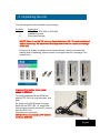
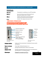
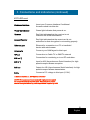
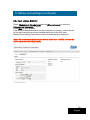
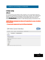
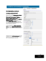
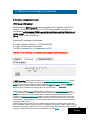
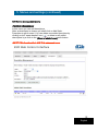
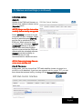
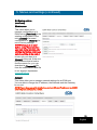
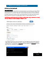
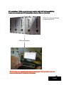
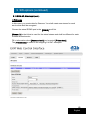
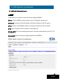
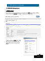
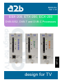
MANUAL
FW 1.33
ESX-200, ETX-200, ECX-200
DVB-S/S2, DVB-T and DVB-C Processors
English
design for TV
1
Content
1.
2.
3.
4.
5.
Introduction
Unpacking the unit
Connections and indications
IP settings
Menus and settings
5.1 Overview menu
5.2 Input settings
5.3 Output settings
5.4 Service management
5.5 System options
6. About remultiplexing QAM
7. About remultiplexing COFDM
8. Installation and Configuration examples
9. SW options
10.SNMP
11.Technical specification EXM
12.Declaration of conformity
13.Glossary
2
English
1 Introduction
Thank you for purchasing an A2B Electronics product. The EXM products is a
revolutionary solutions for reception and modification of satellite, cable or
terrrestrial transmitted TV-content into various transmission formats for cableTV and SMATV.
The ESX-200 is for DVB-S/S2 reception, the ETX-200 is for DVB-T reception
and the ECX-200 for DVB-C reception.
The EXM unit is delivered with hardware and software that supports DVB-S/S2
or DVB-T or DVB-C reception, MPEG2/MPEG4 H.264 AVC, ASI output, VSB
RF modulation with NICAM or A2 audio, SNMP Interface, IP control and
management. All hardware needed for upgrade with software options is
available from the start. See section 9 SW Options for more information.
The EXM unit can be upgraded for enhanced functionality and various formats
for transmission and processing of digital TV content by SW options.
Software options are available from A2B Electronics, please ask us for the
specifications and complete price list of all options.
A2B Electronics AB
Phone: +46 (0)141 229115
E-mail: [email protected]
Also visit our web site www.a2b.se for more information.
3
English
2 Unpacking the unit
The following items are included in the package:
Amount
1
1
2
Description
ESX-200 or ETX-200 or ECX-200
Installation guide
Front panel screws
NOTE! There is no SW CD, nor any Control Software CD. The unit is delivered
with all necessary SW embedded including web server for control and settings
of the unit.
Every unit is quality controlled by us before delivery. Should any items be
missing when unpacking, please contact our support service (see page 3 for
contact info).
Important information about power
supply to EXM unit
To avoid problems with the EXM unit
and/or EPP-100 it is very important that
both
DC plugs on the EXM power cord are
fitted into the EPP-100, i.e. each EXM
unit needs to be fed from two DC outputs
from the EPP-100.
(See picture to the right).
NOTE! Never connect two EPP units to
feed one EXM unit
4
English
3 Connections and indications
ESX-200
Common Interface slot
Antenna in
Power on indicator
DC in
QPSK/8PSK Rx error
indicator
A/V out
ASI in
Access/Tx error
indicator
ASI out
RF out
Ethernet port (RJ 45)
for control, settings,
IPTV out and SNMP
Front panel view of
ESX-200
Rear panel view of
ESX-200
Common Interface
Insert your Common Interface Conditional
Access module into this slot
Power on indicator
Green light indicates that power is on.
Rx error
Red light indicates that the tuner is not
locked to the satellite transmission.
Access/Tx error
Red light indicates that the smart card is not
authorised or that decryption is not working properly.
Ethernet port
Ethernet for connection to a PC or handheld
device with web browser
Antenna in
Connect your outdoor unit (LNB) to this input.
RF out
Connection to Cable TV or SMATV network.
(continued)
5
English
3 Connections and indications (continued)
ESX-200 cont.
A/V out *)
Connection for monitoring or to an RF modulator.
ASI in *)
Input for ASI (Asynchronous Serial Interface) for
high speed transport stream reception.
ASI out
Output for ASI (Asynchronous Serial Interface)
for high speed transport stream transmission.
DC in
Connect a DC voltage to this input (6-10V).
*) Optional function i.e. SW option is needed
NOTE! We recommend to use only A2B original power supply
for correct functionality and life cycle. Warranty will be void in
case of damages caused by power supplies not supplied by A2B.
ETX-200
Common Interface slot
Antenna
in
DC in
A/V out
Power on indicator
COFDM Rx error
indicator
ASI in
Access/Tx error
indicator
ASI out
Ethernet port (RJ 45) for
control, settings
IPTV out and SNMP
Front panel view of
ETX-200
RF out
Rear panel view of
ETX-200
Common Interface
Insert your Common Interface Conditional Access module
into this slot
Power on indicator
Green light indicates that power is on.
Rx error
Red light indicates that the receiver is not locked.
Access/Tx error
Red light indicates that the smart card is not authorised or
that decryption is not working properly.
Ethernet port
Ethernet for connection to a PC or
handheld device with web browser
6
English
3 Connections and indications (continued)
ETX-200 cont.
Antenna in
Connect your outdoor aerial to this input.
RF out
Connection to Cable TV or SMATV network
A/V out *)
Connection for monitoring or to an RF
modulator.
ASI in *)
Input for ASI (Asynchronous Serial Interface)
for high speed transport stream reception.
ASI out
Output for ASI (Asynchronous Serial Interface)
for high speed transport stream transmission.
DC in
Connect a DC voltage to this input (6-10V).
*) Optional function i.e. SW option is needed
NOTE! We recommend to use only A2B original power supply
for correct functionality and life cycle. Warranty will be void in
case of damages caused by power supplies not supplied by A2B.
ECX-200
Common Interface slot
Power on indicator
QAM Rx error indicator
Access/Tx error
indicator
Ethernet port (RJ 45)
for control, settings,
IPTV out and SNMP
Front panel view of
ECX-200
Antenna
in
DC in
A/V out
ASI in
ASI out
RF out
Rear panel view of
ECX-200
7
English
3 Connections and indications (continued)
ECX-200 cont.
Common Interface
Insert your Common Interface Conditional
Access module into this slot
Power on indicator
Green light indicates that power is on.
Rx error
Red light indicates that the receiver is not
locked to the QAM transmission.
Access/Tx error
Red light indicates that the smart card is not
authorised or that decryption is not working properly
Ethernet port
Ethernet for connection to a PC or handheld
device with web browser
Antenna in
Connect your QAM signal to this input.
RF out
Connection to Cable TV or SMATV network
A/V out *)
Connection for monitoring or to an RF modulator.
ASI in *)
Input for ASI (Asynchronous Serial Interface) for high
speed transport stream reception.
ASI out
Output for ASI (Asynchronous Serial Interface) for high
speed transport stream transmission.
DC in
Connect a DC voltage to this input (6-10V).
*) Optional function i.e. SW Options is needed
NOTE! We recommend to use only A2B original power supply
for correct functionality and life cycle. Warranty will be void in
case of damages caused by power supplies not supplied by A2B.
8
English
4 IP Settings
EXM units has an embedded web
server allowing standard web
browsers (Internet Explorer, Firefox,
Opera etc.) to connect to the unit for
settings and management.
No controller software is needed.
The EXM unit has by default a static
IP address for connecting your PC to
the unit.
The EXM unit is delivered with IP
address: 192.168.0.20. First time
installation requires that you set a
static IP address on your computer.
For example set your PC to IP
address: 192.168.0.19 and Net
mask: 255.255.255.0
9
English
4 IP Settings (continued)
4.1 TCP/IP settings for Windows XP (setting your PC to 192.168.0.19)
Click ”Start”, select ”Control panel” and select ”Network connections” and then
select “Network and Internet settings”.”Right click” on [Settings for local network]
and select [Properties].
In Properties click [Internet protocol
(TCP/IP)] and select [Properties].
Select [Use this IP adress] and write:
192.168.0.19 and select [Net mask]
255.255.255.0. Click [OK] and then
click [Close].
NOTE! For PC with other Operating
Systems (OS) than Windows, please
consult the Owners manual for your PC
for [IP/Network settings].
4.2 Connecting your PC to EXM unit
Connect the EXM unit to a DC power supply (EPP-100 or ESP-110).
See section 7 for installation.
Next connect your PC to the EXM unit with a network cable.
Start your web browser (Internet Explorer, Firefox, Opera etc.) and write the IP
address 192.168.0.20 in the address field in your browser.
10
English
4 IP Settings (continued)
4.3. Settings of IP in unit
Click on [System options] menu
and then click on [Network] for
settings of IP address, Netmask
and Gateway for the EXM unit.
5 Menus and settings
All necessary settings can be made in the web GUI via an web browser. When
first connection is made with the EXM unit you will see the Overview menu.
5.1.a Overview menu, Current settings
Contains information of current input and output signals, if the tuner is locked to a
signal, firmware version, bootloader version, hardware revision, serial number,
current IP Network settings including the MAC address. You can also type a
name and an description for the unit.
11
English
5 Menus and settings (continued)
5.1.b Overview menu, Installation Overview
In this menu you can see all units that are connected together in a Head End. You
can see information of IP address, serial numbers, Firmware version, Input, Output,
ASI source, NID, TSID and Uptime. On the left side of the [IP Address] you will have
a symbol for all units that’s selected as “Output MUX” units. Output MUX units
means that those units send, over IP (through the switch), information regarding NIT,
SDT and EIT.
Sorting can be done for IP address or for NID (Network ID).
NOTE! All units must be interconnected through a switch to get this Installation
Overview to work correct.
Symbol showing that this is an “Output MUX” unit
12
English
5 Menus and settings (continued)
5.1.c Overview menu,
Software options
In this menu you can
see what software
options there is in the
unit.
NOTE! The picture
beside shows a unit with
sw option EXM-ALL2
5.1.d Overview menu, Conformance
The EXM products are tested and validated to conform to standards and
application specifications. In the Conformance menu under Overview, some of
these conformances are listed.
13
English
5 Menus and settings (continued)
To continue with settings click on [Input] name in the banner.
5.2.a Input settings ESX-200
Select the modulation type you want to receive. If you choose DVB-S2 you also
can select between QPSK, 8PSK or 16 QAM.
Choose fixed or universal LNB. Set the Polarisation. Voltage, FEC and 22 kHz
tone you normally set to “Auto” if you have connected the EXM unit to an
Universal LNB or a switch with same functionality as a Universal LNB. You can
also select DiSEqC type switch
(4 ports) and what port to connect to.
Finally enter the correct Symbol rate and click on [Set] and then enter the
Transponder frequency and click on [Set]. The available services are listed to the
right.
We suggest that you consult: http://en.kingofsat.net/ or another web site for
correct parameters for the services you intend to use.
The input level should be higher than -65 dBm, preferably more than -50 dBm
and max -25 dBm and C/N should read more than 10 dB.
If only “ASI in” is used you can “Disable” the tuner.
Note! Inverted spectrum is sometimes used in C-band transmissions and is set
automatically by auto detection.
14
English
5 Menus and settings (continued)
5.2.b Input settings, ETX-200
Select the bandwith of the channel you want to receive. Next select the channel
number according to CCIR or enter the correct frequency (in MHz). Be sure to press
[Set] to enter the frequency to the ETX-200.
A list of the available services from the multiplex you tuned to, will be shown on the
right hand side.
Below [Tuner settings] information of the received signal is displayed.
If only ”ASI in” is used you can ”Disable” the tuner at [Input source].
We suggest that you consult your local terrestrial operator for correct parameters for
each multiplex you want to receive.
Note! We recommend that the [Level] reading is between
-31dBm to -55 dBm and C/N better than 25 dB for best performance.
15
English
5 Menus and settings (continued)
5.2.c Input settings, ECX-200
Select [Modulation], [Symbol rate] and the [Channel name] or enter the
[Transponder frequency] (in MHz).
Press [Set] to save settings.
A list of the available services from the multiplex you tuned to, will be shown
on the right hand side and also available services via the ASI input.
Below [Tuner settings] information of the received signal is displayed.
Note! We recommend that the input level is better than -45dBm and that the
C/N is better than 36 dB (QAM64).
16
English
5 Menus and settings (continued)
5.2.c Input settings, IP Insertion
Click on the IP insertion tab to get the IP insertion menu. In this menu you can
insert an IP stream (max 2Mb/s) for use with EPG (PID 18), OTA or Info TV
input ( via VLC Player). You can type an alias for the IP input and do settings for
incoming IPv4 address, Port number, replace input PID, Remove PID:s and
Remove Null Packets.
NOTE! If the IP Insertion is used for EPG (EIT), PID 18 must be disabled in PID
management to avoid PID collision.
17
English
5 Menus and settings (continued)
5.3 Output settings
ASI mode
The output selection ASI disables all RF modulation on the outputs and all selected
services will be transmitted only through the ASI output connector. ASI is a high speed
interface for digital TV transport streams. Use this output mode if you run IPTV out.
Under [Configure bitrate] you can select the output bitrate which is the maximum
bitrate for both ASI in 1) and for ASI out . After choosing output you must click on “Set”
NOTE! With Basic functionality the bitrate of ASI output will be the same as the bitrate
at the tuner input.
1) Sw option with remux needed to get the ASI input functionality.
18
English
5 Menus and settings (continued)
5.3 Output settings (continued)
Selection of Output MUX
In the Output menu there is an new “click box” where you click to select an unit as an
“Output MUX unit”. This means that by choosing all units with COFDM or QAM as
output, those units will exchange all necessary information to build correct tables for
NIT, SDT and EIT. In units that is not chosen as Output MUX, this information is not
sended out through the connected switch to other units.
NOTE1 All units must be interconnected through a switch to get this [Output MUX
selection] to work correct ( SI information is sent on port 16000).
19
English
5 Menus and settings (continued)
5.3 Output settings (continued)
Analogue mode
The selection [Analogue] is set as
factory default as RF output .
Country specific settings can be
done by selecting [Country]. By
selecting a specific country,
transmission standard and
languages are automatically preset.
[Audio language] gives you the
choosen language if there is more
than one language in the received
signal.
[Audio level] can be adjusted
between +3 to -9 dB.
[Subtitling type], [Subtitle priority]
and [Subtitle charset] can be
selected as well as [Subtitle
conversion] and [Subtitle WSS].
20
English
5 Menus and settings (continued)
5.3 Output settings (continued)
Analogue mode (continued)
If you click on the [Advanced settings]
text line you can do settings for
[Country], [Video system], [Audio
system], [Audio dual mono] and adjust
[Mono subcarrier level] and/or [Stereo
subcarrier level] if necessary.
When [Audio dual mono] is selected
you have to set Audio language for the
correct priority of sound.
In the scroll list for [Mono subcarrier
level] and for [Mono subcarrier level]
you can also switch the subcarrier(s) to
Off.
Adjustment for [A/V Audio level] is also
possible to do if the SW option “EXMAV” is downloaded in the unit.
21
English
5 Menus and settings (continued)
5.3 Output settings (continued)
Analogue mode (continued)
It is possible to select scaling of the
picture format to fit with connected
TV sets. This is handled in the
[Video conversion] drop down list
where it’s possible to choose
between the different types. [Video
WSS] (Wide Screen Signalling) is
available in the video for signalling
of the aspect ratio to be displayed by
the TV sets.
[Configured Bitrate] can be set and
this is the bitrate at the ASI output.
[Radio Channel OSD] gives you the
possibility to display the name of a
radio channel on connected TV
sets. You can choose Bg colour
(background colour) and Text colour
of the Radio channel name.
[Attenuation] can be chosen from
0 to -31 dB
You can select output [Channel
name] (E2 to E69) or [Frequency]
within steps of 1 kHz (e.g. 316,167
MHz) in all three output modes
(Analogue, COFDM or QAM).
Click [Set] to save settings.
NOTE! Only click on [Set] if you
have typed a frequency !
22
English
5 Menus and settings (continued)
5.3 Output settings (continued)
QAM mode (SW option)
When selecting [QAM] DVB-C output,
there are settings for [Channel name]
(E2 to E69) or [Frequency],
[Constellation] (16, 32, 64, 128 or
256QAM), [Baud rate] (kBaud) and
[Attenuation]
(0 to -31dB). Click [Set] to save
settings (settings without scroll list).
NOTE! Some of the choices needs
optional software to be uploaded
before they can be selected. .
See page 35 for bit rates
COFDM mode (SW option)
For [COFDM] output you can
select [Channel name] (E2 to E69)
or [Frequency] and [Attenuation]
from 0 to -31dB. You can also
select bandwidth (6,7 or 8 MHz).
For max recommended output
bitrate see page 31.
Click [Set] to save [Frequency] and
[Attenuation] .
COFDM modulation settings are
2k, 64QAM, [FEC] 5/6 or 7/8 and
[Guard Interval] ¼, 1/8, 1/16 or
1/32
Click [Service management] to
select service(s) and or create new
multiplexes.
23
English
5 Menus and settings (continued)
5.3 Output settings (continued)
IPTV mode (SW option)
When selecting [IPTV output], there are settings for IP address and for Port
number. To be sure that the TS out on IPTV running stable over time, we
recommend not to exceed 38Mb/s as configured bitrate and that Output is set
to ASI output. After settings of IP address and port are made you click on the
[Start] button to start streaming
Following IP addresses can be used:
For UDP multicast: 239.0.0.1 to 239.255.255.254
For UDP unicast: Other IP adresses
For UDP broadcast: ALL IP addresses x.x.x.255
NOTE! To run IPTV the used switch must support IGMP Snooping.*)
*) IGMP snooping is the process of listening to Internet Group Management Protocol (IGMP)
network traffic. IGMP snooping, as implied by the name, is a feature that allows a network
switch to listen in on the IGMP conversation between hosts and routers. By listening to these
conversations the switch maintains a map of which links need which IP multicast streams.
Multicasts may be filtered from the links which do not need them.
A switch will, by default, flood multicast traffic to all the ports in a broadcast domain (or the
VLAN equivalent). Multicast can cause unnecessary load on host devices by requiring them to
process packets they have not solicited. When purposefully exploited this is known as one
variation of a denial-of-service attack. IGMP snooping is designed to prevent hosts on a local
network from receiving traffic for a multicast group they have not explicitly joined. It provides
switches with a mechanism to prune multicast traffic from links that do not contain a multicast
listener (an IGMP client).
IGMP snooping allows a switch to only forward multicast traffic to the links that have solicited
them. Essentially, IGMP snooping is a layer 2 optimization for the layer 3 IGMP. IGMP snooping
takes place internally on switches and is not a protocol feature. Snooping is therefore especially
useful for bandwidth-intensive IP multicast applications such as IPTV.
24
English
5 Menus and settings (continued)
5.4 Service Management
Service selection
The Service selection menu gives an
overview of available services from
tuner or IP in and/or the ASI input (if
enabled). Remultiplexing (remuxing)
is possible after downloading an
appropriate SW option. To build your
own MUX you combine several
incoming services. Just click in the
dialog boxes for chosing a service as
Digital out and/or Analogue out. If a
chosen service is encrypted you click
in the CI box for decryption. When a
choice is made the dialog box
change to green colour.
In the CI source scroll list you
choose if decryption on services
coming from tuner or ASI in.
The ASI output automatically
contains the services you have
selected for [Digital output].
NOTE! To decrypt more than one service
requires a sw option that include remux and
a multidecryption CA module and a
smartcard that is activated for more than
one service. Some smartcards can handle
three or more services at a time. Please
refer to your smartcard service provider and
or program provider for further information.
The red colour of the CI
box indicate that CI
source is tuner i.e. no
decryption can be made
on services from ASI in
In this menu you can also see the
actual (instantaneous) “Payload
bitrate” and the “Configured bitrate”.
This helps you to avoid overload for
the output (see page 35 and 36 for
information).
By a click on the [Edit] icon you can
do settings or changes for Service
name, Service ID (SID) , LCN or HD
LCN. By the icon to the right ( )
you can restore to default value.
25
English
5 Menus and settings (continued)
5.4 Service management (cont.)
Service selection, LCN settings
Before starting, ensure that you
have selected the correct [Logical
channel type] in the Network
settings submenu.For setting the
LCN (Logical Channel Number)
you click on the [Edit] icon under
the column named [LCN]. Then
you will see a new window where
you can write the actual Logical
Channel Number (LCN) or/and
HD LCN.
NOTE! LCN /HD LCN shall only be set
in EXM units with outgoing muxes. LCN
is not supported in all DVB receivers i.e.
refer to your manufacturer for
specification for the DVB receivers in
your cable TV network. All EXM units
has to be interconnected to a switch to
make the LCN /HD LCNto work
properly.
Network settings
Click the [Network settings] menu to
display the Network settings menu. Here
you can write [Network Provider Name],
[Network ID], [Original Network ID],
[TransportStream ID] and select [Logical
channel type]. When one or more choices
has been made, you have to click on
[Save settings] to store your settings. The
DVB standard recommends following
Network ID ranges:
DVB-S: 0 to 8191 (0 should be avoided)
DVB-T: 8193 to 13568(Boxer in Sweden
use 8945)
DVB-C: 40961 to 65281 (ComHem in
Sweden use 41001 and up)
NOTE! To make Network search to work on STB:s
(Set Top Boxes) that are connected to the cable TV
network you must have all EXM units
interconnected to a switch and also assure that the
Original network ID and the Network ID is set to the
same value in all EXM units with outgoing muxes.
26
English
5 Menus and settings (continued)
CI and Smart card information
This menu allows you to view information about your CA-system
and current subscriptions etc.
There is also an [Advanced settings] menu, but we recommend to NOT
change in this menu if you are not aware of what the effect will be.
If you by mistake have changed any setting you can always click on the
”Reset button” to come back to Default settings.
NOTE! If changes are made, don’t forget to click on ”Save”
27
English
5 Menus and settings (continued)
CI and Smart card information (cont.)
A new functionality in this menu is the possiblity to Disable the Audio and/or
Video Watchdog.
This can be helpful to use the disable possibility if for example one having problem to
get authorisation for a smartcard or if a unit is not installed in the beginning of an ASI
chain and the actual unit is ruinning with a ”timeshare” program where the smartcard
is not authorised for all programs running in a 24 hour period.
NOTE! WD audio and WD video is only in use when a service is chosen as analgoue
in the Service selection menu.
28
English
5 Menus and settings (continued)
5.4 Service management (cont.)
PID management
In this menu you can disable
PID’s in the outgoing digital
transport stream (TS) and you
can “Add PID loop through” via
tuner or ASI. There are columns
showing IN pid, OUT pid and
Source for each PID.
This of importance if you want to
use an external NIT, EIT, TDT or
other PID’s.
NOTE! If you do an Add PID loop
through it is important that you
first Disable the PID if number of
out PID’s are the same. PID
disable is made after CI
29
English
5 Menus and settings (continued)
5.4 Service management (cont.)
Table Management
In this menu you can set static
NIT and static SDT if wanted.
This can be helpful if there are
changes in the transmissions
from the source that is unwanted
to affect the NIT table version to
avoid to get a message “New
channels found, Do you want to
do a new channel search?” on
digital receivers (STB’s or TV’s)
or if the EXM units are not
connected to a switch, static NIT
shall be used.
Actual table version of the NIT
and SDT can be seen on the left
of the scroll lists.
NOTE 1: If you use this function
you must manually change the
number of the static NIT and/or
SDT every time you remove a
service, add a service, change
LCN or do another change that
you want to send the correct table
information to the digital
receivers.
In the Table Configuration you
can see the included tables of
NIT and SDT and the repitition
rate of the tables and the average
output bitrate of those tables.
NOTE 2: The repitition rate can
be adjusted but this shall NOT be
changed in a normal installation.
30
English
5 Menus and settings (continued)
5.4 Service management (cont.)
Descriptor Management
In this menu you can add descriptors.
After an descriptor is chosen you shall click on Add Static
Descriptor to get it saved. You can delete one added descriptor by
clicking on the “waste basket” icon ( ) or delete or all added
descriptors by a click on the [Clear All Static Descr] radio button.
NOTE ! This functionality is ONLY for advanced users.
31
English
5 Menus and settings (continued)
5.5 System options
Upgrade
Update of the EXM unit firmware or
upload of sw options is done via the
[Upgrade] menu.
NOTE! Always read the Instructions
carefully before starting an upgrade.
Select [Browse] and search for the
correct file on your computer. When
the file is selected press [Upload]
and the file is uploaded into the
EXM unit. When upload is ready
you should get a message “Upload
completed”. Always do a power
reset or web reset after finished
upload to ensure that the EXM unit
reboots with the uploaded software.
[Image] gives the possibility to
downgrade but it is only
recommended for advanced users.
NOTE! Removal of wrong files can
cause a non working unit!
Date & Time menu
In this menu, you can chose if the TDT table shall be chosen via tuner in or
via ASI in or be disabled. If you have an external unit for correct TDT you can
then chose that external unit by chosing ASI as “Output (TDT) time source”.
32
English
5 Menus and settings (continued)
5.5 System options
(continued)
Maintenance
This menu allow you to
manage configuration of a
EXM unit by [Download] of the
existing configuration in the
unit, [Upload] of a saved
configuration or [Restore] the
unit to factory settings.
NOTE! Always do a reset
before using Restore button
and also wait 2 minutes after
clicking that button before you
select anything in the web ui.
In here you can also do a
[Restart] of the unit. If the unit
has problems that is hard to
find the reason for, you can
download a [Diagnostic] file
from the unit and send that file
to our support department.
[email protected]
Network
This menu allow you to manage network settings for an EXM unit.
You are able to change the IP address, the Netmask and the Gateway
for an unit.
NOTE! If more than one unit is installed you must set different IP addresses to all EXM
units if they are connected to a switch.
33
English
5 Menus and settings (continued)
5.5 System options (continued)
User control (Users)
In the System Options menu there is a new menu where you are able to set Users. When
“Enable Usercontrol” is chosen you can set the authority of a user as Read or Read and
Write allowance. You click on “Add user” and then make the choice for a user with Read
and Write authorities as Admin and for only Read allowance for other users that shall be
able to Read from unit(s) but not being able to write i.e. make changes in an unit.
NOTE! Always add first user with both Read and Write rights else you have to use a back
door (see below) to be able to change settings in a unit.
If the details for the User control is forgotten, you can disable the User control (login) by
using Telnet. After connecting to the unit by Telnet you will get be asked for Username
and Password. The Username is: designfortv and the password is 123a2b456 After this
login, the unit is available through the web ui.
34
English
6 About remultiplexing QAM out
To be sure that you don’t exceed maximum bit rate for an output MUX, please
control that you don’t select to many services.
If you run a third party SNMP program you can monitor the Output bitrate and
see that the outgoing bitrate is not too high.
See Chapter 9 for more information about SNMP.
The table below gives max bit rates for QAM out from an EXM unit.
NOTE! Due to bit rate fluctuations from statistical multiplexing, we recommend
that you use maximum 85% of the theoretical available bit rate
Output signal Modulation
Baudrate/BW
Theoretical
bitrate (Mb/s)
85 %
QAM
16QAM
6.875 Mbaud/s
25,34
21,54
QAM
32QAM
6,875 Mbaud/s
31,68
26,93
QAM
64QAM
6.875 Mbaud/s
38,01
32,31
QAM
128QAM
6.875 Mbaud/s
44,35
37,70
QAM
256QAM
6.875 Mbaud/s
50,69
43,08
Table 1. Theoretical bit rates for QAM.
The formula for calculating QAM output bitrate is: [ Baudrate x ”A”/(204/188) ]
where ”A” is 4 for 16QAM, 5 for 32QAM, 6 for 64QAM, 7 for 128QAM and 8 for
256QAM mode.
35
English
7 About remultiplexing COFDM out
The table below gives max bit rates for COFDM with modulation 64QAM out.
NOTE! Due to bit rate fluctuations from statistical multiplexing, we recommend
that you use maximum 85% of the theoretical available bit rate
FEC
Guard Interval GI
Bandwitdh
Theoretical
bitrate (Mb/s)
85 %
7/8
1/32
8 MHz
31,67
26,92
7/8
1/16
8 MHz
30,74
26,13
7/8
1/8
8 MHz
29,03
24,67
7/8
1/4
8 MHz
26,13
22,21
5/6
1/32
8 MHz
30,16
25,64
5/6
1/16
8 MHz
29,27
24,88
5/6
1/8
8 MHz
27,65
23,50
5/6
1/4
8 MHz
24,88
21,15
7/8
1/32
7 MHz
27,72
23,56
7/8
1/16
7 MHz
26,90
22,86
7/8
1/8
7 MHz
25,4
21,59
7/8
1/4
7 MHz
22,86
19,43
5/6
1/32
7 MHz
26,39
22,43
5/6
1/16
7 MHz
25,61
21,77
5/6
1/8
7 MHz
24,19
20,56
5/6
1/4
7 MHz
21,77
18,50
36
English
8 Installation and Configuration examples
The EXM unit can be installed either as a stand alone unit (Wall mount kit for single
EXM unit) or in a base unit (EBU-100).
Before connecting power to the EXM unit, make sure that all other
connections have been made. A coaxial cable of good quality with an F-connector
should be connected to the Antenna input and another one from the RF output to
the cable TV network. Connect a power supply and make all necessary settings as
described in section 4 and section 5.
Note! Important information in page 4 about connecting the DC cable.
Installation in a base unit with 5 EXM modules
and common power supply.
Accessories
EPP-100 power
Supply 100W,
11 outputs
ESP-110 single
power supply 25W,
1 output
DC-cable for
EXM unit
A/V cable EXM
ASI cable 250mm
Art no: 103100.02
Art no: 103200.02
Art no: 500200.01
Art no: 500210.01
Art no: 500250.01
EXM wall
mount
EXM style cover
plate 50mm
EXM style cover
plate 20mm
ASI cable 1000mm
Art no: 700004.10
Art no: 700003.10
Art no: 501000.01
EBU-100 Base unit
for 5 EXM unit modules
and power supply
EPP-100
Art no: 121000.01
Art no: 104100.01
37
English
8 Installation and Configuration examples (cont.)
8.1 Configuration examples: Network settings COFDM out, Mux #1
EXM unit #1
192.168.10.21
EXM unit #2
192.168.10.22
ASI
ASI
VSB RF
out
EXM unit #3
192.168.10.23
VSB RF
out
COFDM
out
As you can see the Network ID and Original Network ID (ONID) should be the same in all
units and preferable the same ID as the Main terrestrial operator are using (in Sweden
Teracom and they use 8945 as ONID). Network ID could have another value than the
ONID but most of STB and TV with inbuilt STB will accept same ID for Network ID and
ONID.
To avoid problems between two or more Muxes in a Headend it’s recommended to use
different Transport Stream ID (TSID) for each EXM unit in the same Headend. A rule to
make the TSID easier to remember is to use same TSID as the last digits in the IP
address of the unit. This also makes it easier to remember if a unit shall be replaced.
NetworkProviderName is possible to change. However, if you do not know what STB:s
and TV sets customer use it’s NOT recommended to change. If the owner of the
Headend also provide all STB:s to all households in the Cable TV network this could be
changed.
The choice of Logical channel type is depending on in which country the installation is
made. For the Nordic countries the correct choice is ”Nordig”. This should be chosen
only in the unit with the outgoing MUX i.e. in other units the correct choice is ”Undefined”.
For other countries refer to your DVB specification. Beside Nordig you can choose
between EACEM and Independent Television.
(See next page for configuration of Mux #2).
38
NOTE! All three units has SW option EXM-RT.
English
8 Installation and Configuration examples (cont.)
8.1 Configuration examples: Network settings COFDM out, Mux #2
EXM unit #4
192.168.10.24
EXM unit #5
192.168.10.25
ASI
VSB RF
out
EXM unit #6
192.168.10.26
ASI
VSB RF
out
COFDM
out
As you can see, the Network ID and the Original Network ID (ONID) is the same
as in the units in MUX #1. The only difference is that all units in this Mux has other
Transportstream ID than in MUX #1 (here also chosen as the last digits in the IP
address).
When building a third Mux you shall use the same settings i.e. same Network ID
and ONID but different Transportstream ID.
39
NOTE! All three units has SW option EXM-RT.
English
8 Installation and Configuration examples (cont.)
8.2 Configuration examples: Network settings QAM out, Mux #1
EXM unit #1
192.168.10.21
EXM unit #2
192.168.10.22
ASI
VSB RF
out
EXM unit #3
192.168.10.23
ASI
VSB RF
out
QAM
out
As you can see the Network ID and Original Network ID (ONID) should be the same in all
units and preferable the same ID as the Main Cable operator use (in Sweden ComHem
are using 41001 as Network ID). Network ID could have another value than the ONID but
most of STB:s and TV:s with inbuilt STB will accept same ID for Network ID and ONID.
To avoid problems between two or more Muxes in a Headend it’s recommended to use
different Transport Stream ID (TSID) for each EXM unit in the same Headend. A rule to
make the TSID easier to remember is to use same TSID as the last digits in the IP
address of the unit. This also makes it easier to remember if a unit shall be replaced.
NetworkProviderName is possible to change. However, if you do not know what STB:s
and TV sets customer use it’s NOT recommended to change. If the owner of the Headend
also provide all STB:s to all households in the Cable TV network this could be changed.
The choice of Logical channel type is depending on in which country the installation is
made. For the Nordic countries the correct choice is ”Nordig”. This should be chosen only
in the unit with the outgoing MUX i.e. in other units the correct choice is ”Undefined”. For
other countries refer to your DVB specification. Beside Nordig you can choose between
EACEM and Independent Television.
(See next page for configuration of Mux #2)
40
NOTE! All three units has SW option EXM-RC.
English
8 Installation and Configuration examples (cont.)
8.2 Configuration examples: Network settings QAM out, Mux #2
EXM unit #4
192.168.10.24
EXM unit #5
192.168.10.25
ASI
VSB RF
out
EXM unit #6
192.168.10.26
ASI
VSB RF
out
QAM
out
As you can see, the Network ID and the Original Network ID (ONID) is the same as in
the units in MUX #1. The only difference is that all units in this Mux has other
Transportstream ID than in MUX #1 (here also chosen as the last digits in the IP
address).
When building a third Mux you use the same settings i.e. same Network ID and ONID
but different Transportstream ID.
41
NOTE! All three units has SW option EXM-RC.
English
8.3 Installation of EXM unit units through a switch with DHCP with possibility for
remote management over VPN connection between office and Head end.
EXM unit connected through
a switch with DHCP
VPN connection
NOTE! If you have questions about how to set up the VPN connection, ask your
network administrator for detailed information.
42
English
9 SW options
It is possible to upgrade your EXM unit with one or more SW options. Below you can
read about available options. For price list, contact your distributor, see www.a2b.se ,
Partners.
In the System menu you can see what SW options are presently available in your
EXM unit.
9.1 EXM-Basic, Basic Functionality
If you have purchased a EXM unit without any SW options you have this basic
entitlement which include DVB-S/S2 input and analogue output. ASI output is
available. ASI input is disabled.
NOTE! ASI output is without remux i.e. no table changes are made and ASI out bitrate is transparent
with tuner in.
9.2 EXM-RC, Remux and QAM out
This SW option allows you to do remuxing and QAM modulation.
9.3 EXM-RT, Remux and COFDM out
This SW option allows you to do remuxing and COFDM modulation.
9.4 EXM-RIPout, Remux and IPTV out
This SW option allows you to do remuxing and IPTV out.
9.5 EXM-AV, Audio/Video out
This SW option allows for A/V out at the back plane A/V connector.
9.6 EXM-ALL, software package.
This SW option includes EXM-RC, EXM-RT, EXM-RIPout and EXM-AV
9.7 EXM-ALL2, software package.
This SW option includes EXM-Ripin, EXM-RC, EXM-RT, EXM-RIPout and EXM-AV
9.8 EXM-Demo, software package
31 days evaluation SW option (includes same options as EXM-ALL).
9.9 EXM-Demo2, software package
31 days evaluation SW option (includes same options as EXM-ALL2).
43
English
9 SW options (continued)
9.10 EXM-SC, Simulcrypt
This SW option allows you to encrypt a Mux in an EXM unit. When this SW option
is uploaded to the unit a new menu will be available (see below).
NOTE! Does not include the encryption equipment such as encryption server,
SMS etc.
1.1 ECMG
In this menu you create a ECMG for channels you want to encrypt. As [Alias] you
write a name to more easy remember which ECMG if more than one ECMG are
used..
[Super CAS ID] is the Id that is used for the chosen CA system. Write in hex code
without 0x. Example: 0b000000 (Conax).
[IP address] is the IP address for your Simulcrypt CA server.
[Port] shall be chosen the same as the port in the CA server.
[Channel ID] must be unique for each CA server connection, if more than one
CA server is used.
44
English
9 SW options (continued)
9.11 EXM-SC, Simulcrypt (cont.)
1.2 Streams
In this menu you create data for Streams. You shall create one stream for each
service that shall be encrypted
Choose the actual ECMG port in the [ECMG] scroll list.
[Stream ID] is the id that is used for the actual stream and shall be different for each
created stream/service.
Fill in information about [Access criteria] and eventual [Private data].
The [Private data] is added in the outgoing CA PMT descriptor.
45
English
9 SW options (continued)
9.11 EXM-SC, Simulcrypt (cont.)
1.2 Streams cont.
When a Stream is created you get a new view with possibilities to edit or delete
the created Stream by a click on the icon’s.
It’s also possible to see information about the actual Stream by a click on the Info icon.
Edit view and Info view below
46
English
9 SW options (continued)
9.11 EXM-SC, Simulcrypt (cont.)
1.3 EMM
In this menu you create a connection for the outgoing EMM’s.
[Alias] Give the EMM a name/number. Up to 9 characters can be used.
[Client Id] Choose the Client ID (Super CAS) that is defined in the CA server..
[Port] number for the EMM is written according to the setup in the CA server.
[Pid] can be created if one not chose to use default (0).
[Private CAT] Fill in the eventual private data. The data vill be added in the CAT, CA
Descriptor.
[Bandwidth] Set the maximum outgoing bitrate for the EMM:s
47
English
9 SW options (continued)
9.11 EXM-SC, Simulcrypt (cont.)
1.3 EMM, continue
If something needs to be changed you can click on the [Edit] icon (
and/or click on the [Delete] icon (
) for deleting an created EMM.
) for editing
There is also an [Info] icon (
)
and a click on this gives you
information about the created
EMM
48
English
9 SW options (continued)
9.11 EXM-SC, Simulcrypt (cont.)
1.4 Services
In this menu you chose services that shall be encrypted by a click on the green icon
( ). It now changesd to a red icon ( ). By a click on that icon again the service will
be non encrypted. In the Service selection menu you can see what service(s) that’s
encrypted by the ”key symbol” on the Type icon.
NOTE! Ensure that you first have done all necessary settings due to the information
earlier described in this document and that you have connection to the CA server.
49
English
10 SNMP
With FW from version 1.22 and later in the EXM unit you are able to use the
SNMP Interface for monitoring the EXM unit. To enter the SNMP menu on the
unit, write: /snmp.html after the IP address in the web browser.
Example: 192.168.0.20/snmp.html
In the [SNMP agent] part of the menu you can start the SNMP agent, select
Listen port, Read community, Write community.
In the [SNMP traps] part of this menu you can select Dest. Address (IP
address to the PC that is listening), Dest. port and Community.
SNMP agent = the “agent” (SW) that
listens for GET or SET
Listen port = port to listen to
Read community = “password” for
Management System to be able to access
SNMP agents for GET commands.
“Public” as default.
Write community = “password” for
Management System to be able to access
SNMP agents for SET commands (not
implemented yet). “Public” as default.
SNMP traps= the “trap” (SW in EXM) that sends information to the
Management System when defined instances occur
Dest. address = IP address to host for Management System
Dest. port = port in MS host
Community = “password” for Management System to be able to access
SNMP traps. “Public” as default.
NOTE! To be able to use the SNMP you need to use a 3rd party program. One
program you can download for trial is http://www.ireasoning.com/mibbrowser.shtml .
Download the a2b-mibs.zip file that is found in the SNMP menu, unzip and copy
50
the two mib files into theMIB map in the 3rd party program.
English
11 Technical specification EXM
Connectors and Interfaces
Control and IP out connector
RF input connector
RF output connector
ASI input connector
ASI output connector
CAM connector
LED Indicator lights
SNMP Interface
A/V out connector
RJ-45, 10/100 BaseT
F female, 75 Ω
F female, 75 Ω
BNC female, 75 Ω
BNC female, 75 Ω
PCMCIA (5 VDC)
Power on, Rx error,
Tx/Access error
RJ-45, 10/100 BaseT
3,5 mm 4 pole
QPSK/8PSK Satellite Receiver ESX-200
Input Frequency
Input Level
Input impedance
Spectral inversion
LNB voltage
22kHz to LNB
DiSEqC 1.1
Max input TS bit rate
DVB compliance
950 – 2150 MHz
-65 to -25 dBm
75 Ω
Yes, Auto for C-band LNB
Auto, Off or 13/18V
programmable.
Max. 400 mA. (short
circuit protected)
Auto, On or Off
programmable
Yes, 4 port switch
> 60 Mbit/s DVB-S, DVB-S2
DVB-S (EN 310 421)
DVB-S2 (EN 312 317)
QAM modulation (SW Option)
QAM modes
Symbol rate
MER (at RF out)
DVB compliance
QAM output frequency
Output level
PSI/SI management
Remultiplexing
16, 32, 64, 128 and 256 QAM
4 – 7.2 Mbaud/s
> 38 dB for 256-QAM
DVB-C (EN 310 429)
47 - 862 MHz (1 kHz step)
Min 105 dBuV (47-470 MHz)
Min 100 dBuV (470-862 MHz)
Yes
Yes
COFDM modulation (SW Option)
COFDM mode
Guard interval
FEC
MER
2K
¼, 1/8, 1/16 or 1/32
5/6 or 7/8
>32 dB
DVB compliance
Max output bit rate
DVB-T (EN 310 744)
26,92 Mbit/s (8 MHz bandwidth)
23,55 Mbit/s (7 MHz bandwidth)
20,19 Mbit/s (6 MHz bandwidth)
47 – 862 MHz (1 kHz step)
Min 100 dBuV (47-470 MHz)
Min 95 dBuV (470-862 MHz)
Yes
Yes
Output frequency
Output level
PSI/SI management
Remultiplexing
COFDM Terrestrial Receiver ETX-200
RF Modulation (analogue)
Input frequency
Input freq step size
Input level range
Input impedance
Input return loss
C/N limit
Bandwidth
DVB compliance
Co/adj channel PAL
Automatic mode change
recovery
Echo performance
Standards
Sound
50 - 858 MHz (centre freq.)
250 kHz
-60 to -31 dBm *)
75 Ω
12 dB
18 dB *)
6/7/8 MHz
DVB-T
Compliant to Nordig 2 PAL
Yes
Compliant to Nordig 2 unified
*) QEF reception with test signal: 8k, 64QAM, 1/8 guard
interval, 2/3 FEC
Modulation video
Modulation mono
Output frequency
Output level
S/N weighted
C/N, broadband
NICAM standards
Power ratio
(Vision/NICAM carrier)
Tolerance
Impedance
B/G, I, D/K, L, M/N
Mono, NICAM stereo or
A2/A2* stereo
VSB AM, neg. or pos.
Audio FM or AM
47 – 862 MHz (1 kHz step)
> 110 dBuV (47-470 MHz)
> 105 dBuV (470-862 MHz)
> 57 dB
> 70 dB
NICAM 728 (EN 310 163)
B/G -20dB,
I -24dB,
D/K -24dB,
L -31dB
+/- 1dB
75 Ω
QAM Cable Receiver ECX-200
Input frequency
Input freq step size
Input level range
Input impedance
Input return loss
QAM mode
Baud rates
C/N limit
Bandwidth
DVB compliance
50 - 858 MHz (centre freq.)
250 kHz
-55 to -25 dBm *)
75 Ω
12 dB
16, 32, 64, 128 or 256 QAM
3100 to 7000 kS/s
26 dB *)
8 MHz
DVB-C
*) QEF reception with test signal: 64QAM, 26 dB C/N
This specification may change without prior notice.
51
English
ASI input (SW option) – output
ASI bit rate
Max payload bitrates:
Input bit rate
Output bit rate
PCR restamping
PSI/SI management
Remultiplexing
Graphical User Interface (GUI)
55 Mbit/s
55 Mbit/s
55 Mbit/s
Yes
Yes
Yes
*)
*)
*) The input, output and throughput bitrate is highly
dependent on the type of application that is running in
the unit.
MPEG Decoder - Audio
Supported formats
Output
Impedance
Output level
Level adjustment
MPEG 1 layer II, AAC HE.
Selection of Dual mono in,
Stereo or Mono
< 100 Ω
0 dBu
+3 to -9dB
MPEG Decoder - Video
Supported formats
Output standards
Impedance
Output level
Aspect Ratio
Teletext
Subtitling
Decryption
Multidecryption
MPEG2 MP@ML, MPEG4 H.264 AVC
PAL, SECAM or NTSC
75 Ω
1 Vpp @ 75 Ω
Letterbox, Pan/Scan,
or conversion Combined (14:9)
programmable, WSS
Insertion in VBI
Teletext or DVB subtitling
Common Interface (PCMCIA 5VDC)
Yes *)
Graphical User Interface for easy set up of complex
systems. Simple handling of remultiplexing
and creation of new multiplexes from any input.
Disable PID’s and create PID loop through makes it more easy to
get the PSI/SI content that you want.
Default settings of PSI/SI tables to avoid clashes in the output
multiplexes.
Simple menu structure for setting input, output and processing
parameters.
Each EXM unit contains an embedded web server.
Standard web browsers (Internet Explorer,
Mozilla Firefox etc.) are supported
IPTV out (SW Option)
*) SW option is needed
Remultiplexing (SW option)
Each ESX-200 contains a remultiplexer for 2 incoming
transport streams. The transports streams can be received
from satellite or IP, and from the ASI input. PID remapping
is made automatically or manually by PID management. LCN
(Logical Channel Number) can be chosen.
The following components can be remultiplexed:
Audio, Video, Subtitling, PAT, PMT, NIT actual, EIT, CAT,
SDT, TDT and TOT
IP connection between EXM units in a system is required for
NIT, EIT other and SDT other.
Max output bit rate
Connector
Output protocol
PSI/SI management
Remultiplexing
2) Single SPTS/MPTS and only IPTV as output
3) Depending on choosen IP address
Multicast = 239.0.0.1 to 239.255.255.254
Unicast = Other IP addresses
Broadcast = All IP addresses x.x.x.255
SNMP
SNMP agents
Payload bitrate
Peak bitrate
Uptime
Tuner locked
Tuner signal level
Tuner SNR (C/N)
Tuner BER
SNMP traps
Tuner locked/unlocked
Cold reboot
Warm reboot
Miscellaneous
Power supply
Power consumption
Dimensions
Weight
Controller
7,5 VDC nom. (6-10 VDC)
Typ. 15 W (excl LNB feed)
165x105x37 mm (excl. connectors)
Approx. 390 g
Embedded web server
Operating temperature
-20 to +50˚C, non-condensing
This specification may change without prior notice.
55 Mbit/s 2)
RJ 45 (same as control)
UDP, Multicast or Unicast 3 )
Yes
Yes
52
English
12 Declaration of Conformity
The document for Declaration of Conformity you will find at www.a2b.se.
Further information at www.a2b.se.
53
English
13 Glossary
DVB
Digital Video Broadcasting (Standardization body)
MPEG-2
Compression format for digital TV
MPEG-4
Compression format for digital TV (SD and HD)
H.264 AVC
Format for compression of the video in HDTV
VSB
Vestigal Side Band (adjacent channel RF modulation)
ASI
Asynchronous Serial Interface (High Speed Interface)
NICAM
Digital sound format for analogue TV transmission
IP
Internet Protocol (defines how data is packetized for Internet broadcast)
IPTV
TV-content packetized for Internet Protocol
DVB-T
Modulation format (COFDM) for terrestrial transmission of digital TV
DVB-C
Modulation format (QAM) for cable transmission of digital TV
DVB-S
Modulation format (QPSK) for satellite transmission of digital TV
DVB-S2
Modulation format (QPSK or 8PSK) for satellite transmission of digital TV
QAM
Modulation standard for digital TV in cable networks
COFDM
Modulation standard for digital TV in terrestrial networks
Remultiplexing
Way of recombining services from different multiplexes
DHCP
Dynamic Host Configuration Protocol is a protocol used by networked devices
(clients) to obtain the parameters necessary for operation in an Internet
Protocol network. This protocol reduces system administration workload,
allowing devices to be added to the network with little or no manual
configuration.
Common Interface
Connector for a PCMCIA module used for decrypting encrypted TV programs.
Modules should comply with the DVB CI standard
SD
Standard definition TV (576i in Europe)
HD
High Definition TV (720p or 1080i)
LCN
Logical Channel Numbers (method to gives TV programs numbers that define
the order the programs appears on a TV or Set Top Box
VPN
Virtual Private Network (secure point to point connection in an unsecure
network)
SMS
Service Management System (system for handling smartcards).
SNMP
Simple Network Management Protocol (SNMP) is used in network
management systems to monitor network-attached devices for conditions that
warrant administrative attention. SNMP is a component of the Internet Protocol
Suite as defined by the Internet Engineering Task Force (IETF). It consists of a
set of standards for network management, including an application layer
protocol, a database schema, and a set of data objects
54
English
Notes
_________________________________________
_________________________________________
_________________________________________
_________________________________________
_________________________________________
_________________________________________
_________________________________________
_________________________________________
_________________________________________
_________________________________________
_________________________________________
_________________________________________
_________________________________________
_________________________________________
_________________________________________
_________________________________________
_________________________________________
_________________________________________
_________________________________________
_________________________________________
55
English
A2B Electronics AB
Södra Allén 23-25, 591 37 Motala
P.O. Box 14, 591 21 Motala
SWEDEN
Phone +46 141 229100
Fax +46 141 229101
E-mail [email protected]
650200.01 rev L FW1.33
To view our full line of Professional Products, visit our Web site www.a2b.se
www.a2b.se
56