1
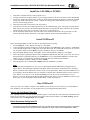
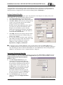
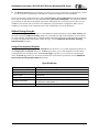
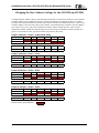
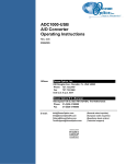
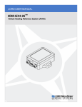
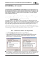
Installation Instructions: ADC1000 & PC2000 (for Windows 95/98 Users)
ADC1000 ISA-bus A/D Converter
The ADC1000 ISA-BUS A/D CONVERTER is a 12-bit, 8-channel, single-ended A/D card that connects our
spectrometers to desktop PCs. The PC2000 PC PLUG-IN SPECTROMETER has our 2048-element linear CCD-array
fiber optic spectrometer mounted onto an ADC1000. This sturdy combination fits easily into a slot in the PC. The
following are directions for installing your ADC1000 and PC2000. Because A/D converter installation goes handin-hand with software installation, you will find directions for installing OOIBase32 Spectrometer Operating
Software included in this section as well.
Each device in or connected to your computer is assigned specific settings; it’s similar to giving each device its
own name so that your computer will know what to call and how to recognize the device. In order for your
ADC1000 or PC2000 to work as a device in your computer, it has to be assigned a Base Address setting and an
IRQ setting. The default settings for each are:
Base Address (I/O Range): 768 decimal (300 hexadecimal)
IRQ (Interrupt Request):
07
These default values are set on the A/D converter. There are dip switches on the A/D board and their positions
determine the values. These default values are set in the operating software as well. Most of the time, these default
settings will work with your computer. However, if you have many devices installed in your computer, you may
have a conflict; other devices may be using these settings. If there is a conflict with another device in your
computer, you must change the positions of the switches on the A/D board and change the values in the software.
For the ADC1000 and PC2000, there is only one bank of switches on the A/D board: the Base Address may be
changed via the first 6 switches and the IRQ may be changed via the last 3 switches. To first check your computer
to see which settings are available, follow the instructions for your Windows operating system.
Find Available Base Address and IRQ Settings
1.
2.
3.
Go to Start | Settings | Control Panel and double-click on the System icon.
Choose the Device Manager tab and double-click on “Computer” at the top of the list.
Under View Resources, find available settings -- numbers unassigned to hardware. Note these available
settings for both the Interrupt request (IRQ) and the Input/output (Base Address). When you first run
OOIBase32, you must enter these values in the “Configure Hardware” dialog box. (Remember that
Input/output settings are expressed in hexadecimal.)
! For most computers, the default settings work well. In the picture above left, it appears that the Printer occupies
IRQ 07, but for most computers, our A/D converters can share the 07 setting with a printer and conflicts will
not arise. All computers have multiple Base Address (Input/output) settings from which to choose.
-1-
Installation Instructions: ADC1000 & PC2000 (for Windows 95/98 Users)
Install the ADC1000 (or PC2000)
1.
2.
3.
4.
5.
6.
Turn off the computer and remove the computer cover.
Ground yourself to the computer chassis or power supply and remove the A/D card from its static-shielded bag.
If necessary, change the position of the switches on the A/D board. Position the switches to match the available
settings you found in the previous section -- numbers not being used by other hardware devices. See pages 5
and 6 for switch setting positions.
Find an open ISA-bus slot and remove the slot protector.
Insert the A/D card into an available expansion slot on the motherboard by gently rocking the card into the slot.
Make sure the card is fully seated in the motherboard before screwing the tab on the A/D card to the computer.
Do not bend the card or move it from side to side once it is seated in the slot.
For the ADC1000, attach the D37 end of the cable to the card and the D25 end to the spectrometer. For the
PC2000, attach the desired optical fiber to the SMA connector on the PC2000. Reinstall the cover.
Install OOIBase32
Before installing OOIBase32, make sure that no other applications are running.
1. Execute Setup.exe. At the “Welcome” dialog box, click Next>.
2. At the “Destination Location” dialog box, accept the default or choose Browse to pick a directory. Click Next>.
3. At the “Backup Replaced Files” dialog box, select either Yes or No. We recommend selecting Yes. If you select
Yes, accept the default or choose Browse to pick a destination directory. Click Next>.
4. Select a Program Manager Group. Click Next>. At the “Start Installation” dialog box, click Next>.
5. Follow all prompts regarding the Spectrometer Configuration diskette that came with your system. For more on
the Spectrometer Configuration diskette, see the Note below. (If you downloaded OOIBase32 from the Ocean
Optics web site, you will not have this diskette. Select No when first asked about the diskette.)
6. At the “Installation Complete” dialog box, choose Finish>.
7. When prompted to do so, restart your computer when the installation is complete.
Note:
In your spectrometer shipment box, you received a Wavelength Calibration Data Sheet wrapped around a
floppy diskette. The Wavelength Calibration Data Sheet and the spectrometer configuration file on the floppy
diskette contain the same information, which is unique to your spectrometer. When you install OOIBase32, you
are prompted to insert this diskette into your computer so that this data is installed with the software. However,
if the diskette is ever lost, or if you downloaded OOIBase32 from the our web site and did not receive a
diskette, you can use the data on the Wavelength Calibration Data Sheet to enter into OOIBase32 fields. (If you
need a copy of your Wavelength Calibration Data Sheet, contact Ocean Optics.)
Run OOIBase32
After you restart your computer, navigate to the OOIBase32 icon and select it. The first time you run OOIBase32
after installation, you must follow several prompts before you can begin taking measurements.
Operator and Serial Number Dialog Box
First, a prompt to enter a user name and serial number appears. Certain data files will include this information in the
header. (If, at a later date, you wish to change the operator name and serial number, select Edit | Settings from the
menu and then choose the Registration tab.) Click OK.
Default Spectrometer Configuration File
Next, the following message appears:
This appears to be the first time OOIBase32 has been executed. Please select a default spectrometer configuration
file from the following screen. This spectrometer configuration file will be used each time OOIBase32 is started.
-2-
Installation Instructions: ADC1000 & PC2000 (for Windows 95/98 Users)
A file open dialog box then appears. Navigate to the OOIBase32 directory, and choose the default spectrometer
configuration file -- the file with .spec as the extension, preceded by the serial number of your spectrometer. (A
default spectrometer configuration file will be named something similar to I2J613.spec.)
Configure Hardware Dialog Box
Next, the Configure Hardware dialog box opens. The parameters in this dialog box are usually set only once -when OOIBase32 is first installed and the software first opens.
1. Under Spectrometer Type, choose S2000/PC2000.
2. Under A/D Converter Type, choose ADC1000/PC2000.
3. Under Base Address, choose the same setting as the dip
switches on the A/D board (and the same available
setting you found in your computer).
Remember that the Input/output Range (Base Address)
you selected was expressed in hexadecimal. In this
dialog box, the base address is given in decimal,
followed by the hexadecimal equivalent in parenthesis.
For example, “768 (0x0300)” gives the base address as
768 decimal and 300 hexadecimal.
4.
5.
Under IRQ, choose the same setting as the dip switches
on the A/D board (and the same available setting you
found in your computer).
For your setup, only these parameters apply. (Ignore the
other settings; they apply to other A/D converters.) Click
OK. You can always change these settings once
OOIBase32 is fully operational by selecting
Spectrometer | Configure | A/D Interface.
! If you do not see the “Configure Hardware” screen, exit the software. Then select Start | Run and type
C:\windows\ooidrv.ini. Notepad will open. Edit this file for our device driver by finding the “Initialized”
entry and making sure this line reads Initialized=0. Save the OOIDRV.INI file and exit Notepad. Restart
OOIBase32. You should now see the “Configure Hardware” dialog box.
Spectrometer Configuration Dialog Box
Now that OOIBase32 is running, you need to configure your system. Select Spectrometer | Configure from the
menu. Go through each page in the Spectrometer Configuration dialog box to set system parameters. (See the
OOIBase32 Spectrometer Operating Software
Manual for details.)
" In the Wavelength Calibration page, the
"
coefficients for each spectrometer channel in
your system have already been loaded as part of
the spectrometer configuration file that came on
a floppy diskette with your spectrometer. (See
the Note on page 2.) If you did not receive this
floppy diskette, you can enter the wavelength
coefficients of your system from the
Wavelength Calibration Data Sheet that came
with your spectrometer. Check the Enabled box
for each spectrometer channel in your system.
In the A/D Interface page, enter the same
values as you did in the Configure Hardware
dialog box.
-3-
Installation Instructions: ADC1000 & PC2000 (for Windows 95/98 Users)
"
The Detector Linearity page in this dialog box allows you to enter coefficients for an algorthim that corrects
for rare occurances of non-linearity of the detector. Contact Ocean Optics for more information.
Save the spectrometer configuration file by choosing Spectrometer | Save Configuration As from the OOIBase32
menu. You can rename the file or use the default file name ([your serial number].spec). You will then be asked if
you would like to make this file the default spectrometer configuration file. Choose Yes. The next time you run
OOIBase32, the software will use the file as the standard for your spectrometer configuration. When you exit
OOIBase32, any changes to the configuration file will be automatically saved to the default file.
OOIBase32 Settings Dialog Box
At this point, it is a good idea to configure several OOIBase32 operation parameters. Choose Edit | Settings from
the menu to open the OOIBase32 Settings dialog box. Go through each page of this dialog box to select options
for saving, opening, and printing data; to configure default setting files; and to select other important options such
as storing and copying data and choosing warning messages. (See the OOIBase32 Spectrometer Operating
Software Manual for details.)
Configure Data Acquisition Dialog Box
Finally, select Spectrum | Configure Data Acquisition from the menu to set your data acquisition parameters in
the Configure Data Acquisition dialog box. The Basic page allows you to set the integration time and choose
averaging and boxcar smoothing values. The External Trigger page allows you to specify the external trigger
mode. The Strobe page allows you to control external strobe events with the spectrometer. (See the OOIBase32
Spectrometer Operating Software Manual for details.)
Specifications
Board architecture/design:
Resolution:
Sampling frequency:
Interface cable:
Multiple-channel capability:
Installation parameters:
Integration time:
half-length ISA-bus card for single slot in desktop PC
12-bit
1 MHz (maximum)
For the ADC1000: 37-pin connector to A/D card and 25-pin connector to
spectrometer
up to 8 spectrometer channels for S2000/PC2000 spectrometers
set dip switch for Base Address (default = 768 decimal, 300 hexadecimal)
set dip switch for IRQ (default = 7)
3 milliseconds to 60 seconds with S2000 series spectrometers
-4-
Installation Instructions: ADC1000 & PC2000 (for Windows 95/98 Users)
Changing the Base Address Settings for the ADC1000 and PC2000
To change the Base Address settings on the ADC1000 and PC2000, see the bank of switches on the A/D board:
The Base Address may be changed via the first 6 switches (the IRQ may be changed via the last 3 switches).
Switches in the OFF position have the decimal values shown. Switches in the ON position have a value of zero.
The Base Address is the sum of the values of the switches. In the default setting, switches 5 and 6 are added to
give a total of 768. A few of the many combinations for Base Address settings are below. After you have
changed the switches, reinstall the card and change the software settings to match the hardware settings. (See
pages 1-4 for instructions.) The gray block indicates the position of the switch.
Example: 768 decimal = Hex300 = 0x300 (Default Setting)
Switch #
1
2
3
4
5
6
16
32
64
128
256
512
256
512
5
6
256
512
5
6
256
512
5
6
256
512
ON
OFF
Decimal equivalent
Value as shown
Example: 784 decimal = Hex310 = 0x310
Switch #
1
2
3
4
ON
OFF
Value as shown
16
Example: 800 decimal = Hex320 = 0x320
Switch #
1
2
3
4
ON
OFF
Value as shown
32
Example: 816 decimal = Hex330 = 0x330
Switch #
1
2
16
32
3
4
ON
OFF
Value as shown
sw itch is in the on, upw ard position =
-5-
Installation Instructions: ADC1000 & PC2000 (for Windows 95/98 Users)
Changing the Interrupt Request Settings for the ADC1000 and PC2000
To change the IRQ settings on the ADC1000 and PC2000, see the bank of switches on the A/D board: The IRQ
may be changed via the last 3 switches. The following matrix defines the different IRQ settings by switch positions
7, 8, and 9. In the default setting, the IRQ is set to 7. Other combinations for IRQ settings are below. After you
have changed the switches, reinstall the card and change the software settings to match the hardware settings. (See
pages 1-4 for instructions.) The gray block indicates the position of the switch.
Interrupt Request 3
Switch #
7
8
9
7
8
9
7
8
9
ON
OFF
Interrupt Request 4
Switch #
ON
OFF
Interrupt Request 5
Switch #
ON
OFF
Interrupt Request 7 (Default Setting)
Switch #
7
8
9
7
8
9
7
8
9
7
8
9
ON
OFF
Interrupt Request 9
Switch #
ON
OFF
Interrupt Request 10
Switch #
ON
OFF
Interrupt Request 11
Switch #
ON
OFF
sw itch is in the on, upw ard position =
-6-