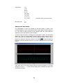
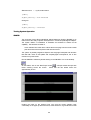
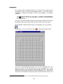
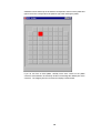
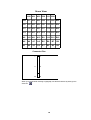
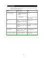
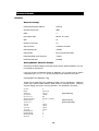
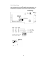
1
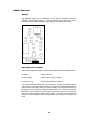
University of Kent
at Canterbury
SNORS+
Installation Guide
Version 6
September 2000
This device complies with the
requirements of EC directive
93/42/EEC and EN60601-1.
University of Kent at Canterbury
Manufactured by:
Medical Electronics
Electronic Engineering Laboratory
University of Kent
Canterbury
Kent
CT2 7NT
UK
SNORS+ is a modular system.
This manual covers the following modules:
SNORS+ Base Unit
SNORS Mask (Adult)
SNORS Mask (Child)
Linguagraph
SNORS Audio Unit
Information regarding the use of other manufacturer’s
devices, specifically as part of the SNORS+ system, is
also provided.
Contents
Contents .........................................................................................................i
Introduction ................................................................................................ 1
Recommended Computer Specification...................................................... 1
Basic Operation.........................................................................................................................1
Use with Video Option...............................................................................................................1
Preparing the Computer............................................................................... 1
Installation of Core Hardware and Software........................................... 3
Installation..................................................................................................... 3
Hardware ...................................................................................................................................3
SNORS+ software.....................................................................................................................3
®
Keithley memory manager......................................................................................................4
Desktop shortcut........................................................................................................................5
Uninstalling SNORS+................................................................................... 5
Testing System Operation ........................................................................... 5
Setting up Audio Record/Playback...........................................................................................7
SNORS+ Multiparameter System............................................................. 8
Hardware set-up........................................................................................... 8
Software installation ..................................................................................... 9
SNORS +.cfg file setup ................................................................................ 9
Setting Sound Card Polarity .................................................................................................. 10
Testing System Operation ......................................................................... 11
SNORS....................................................................................................... 11
Linguagraph ............................................................................................... 13
Laryngograph® ........................................................................................... 16
Troubleshooting....................................................................................... 17
Technical Details...................................................................................... 18
Interface...................................................................................................... 18
I
Hardware Settings.................................................................................................................. 18
Altering SNORS+ Hardware Settings ................................................................................... 18
SNORS+ Audio Unit................................................................................... 20
Settings ................................................................................................................................... 20
Altering Mic Power Settings................................................................................................... 20
Specification ............................................................................................. 21
Input channels ............................................................................................ 21
SNORS ................................................................................................................................... 21
Linguagraph............................................................................................................................ 21
®
Laryngograph ........................................................................................................................ 21
Auxiliary Channel.................................................................................................................... 21
Sound card ............................................................................................................................. 21
Video card............................................................................................................................... 21
Scope channels available for display......................................................... 21
2-D displays available ................................................................................ 22
Wave displays available............................................................................. 22
Speech analysis displays available ........................................................... 22
Sampling rates ........................................................................................... 22
With electropalatography enabled......................................................................................... 22
Without electropalatography enabled.................................................................................... 23
Audio sampling rates (for Sp and Lx) ........................................................ 23
Video frame rates....................................................................................... 23
Channel bandwidths................................................................................... 23
Speech intensity ..................................................................................................................... 23
Airflow...................................................................................................................................... 23
Lx............................................................................................................................................. 23
Channel sensitivities................................................................................... 23
Typical accuracy......................................................................................... 23
Typical synchronisation.............................................................................. 23
II
Introduction
SNORS+ is a synchronous, multiparameter speech workstation. It can be used for
therapy in real-time, for assessment, and for measurement of outcome. SNORS+ can
also be used as a stand-alone system. It can be any or all of the following:
SNORS nasal/oral airflow system, for inferring velopharyngeal function.
Linguagraph electropalatography system, for measuring tongue-palate contact.
®
Laryngograph system, for measuring vocal fold activity.
It is recommended that the core system is first installed and tested and that users are
allowed to become familiar with this base system before attempting to set-up the full,
multiparameter system.
This manual explains how to install the University of Kent, SNORS+ multiparameter
speech workstation.
Setting up SNORS+ involves the installation of one (or two) card(s) within the host
computer. It is strongly recommended that a person experienced with PC hardware
undertakes this task.
Recommended Computer Specification
Basic Operation
Pentium 233 MHz processor.
64 MB RAM.
2 GB Hard Disk Drive.
Removable storage device, such as ZIP or LS120 drives.
Use with Video Option
Pentium II 400 MHz processor.
256 MB RAM.
10 GB Hard Disk Drive.
Removable storage device, such as JAZ or PD drives, or a CD writer.
Preparing the Computer
SNORS+ uses a proprietary, ISA bus, data acquisition card, so the PC on which the
system is to be installed must have a vacant ISA bus slot.
The data acquisition card uses the following system resources: Address 310
(hexadecimal), DMA 3 and Interrupt IRQ 7. If your system allows, it is strongly
recommended that these resources be reserved in the BIOS. This will ensure that
®
Windows 95/98 does not allocate them to other hardware. Alternatively, system
1
®
resources may be reserved within Windows (Start Menu – Settings – Control Panel –
System – Device manager – Reserve Resources).
If video recording is required, a proprietary, PCI bus, video frame-grabber card is also
used. This must be installed in a spare PCI slot. As PCI cards are “plug and play”, it
is not necessary to reserve resources for this card.
The SNORS+ software package is a 32-bit application, designed to run under
®
®
®
Windows 95 or Windows 98 . Please make sure that Windows is properly installed
on the PC, before attempting to load the SNORS+ software.
Accelerated graphics cards use extensive resources, which can cause SNORS+ to
miss samples. It is most important that graphics acceleration is turned down, to avoid
this potential problem.
SNORS+ is a powerful application, which also makes extensive use of computer
resources. To ensure that the system performs to its full potential, it is strongly
recommended that a computer be dedicated to the SNORS+ system and that no other
applications are installed on it.
Finally, use of the synchronous audio recording
and playback facility provided under SNORS+
®
requires a Windows 95/98 compatible sound
card. If you wish to use this facility, please ensure
that your sound card is installed and properly set
up, prior to installing SNORS+. (Install all required
drivers and then, from the “Sound Recorder”
dialog box, check the “Line” select box and set its
recording volume and balance controls to half
way).
2
Installation of Core Hardware and Software
The core hardware consists of:
An electronics unit – the SNORS+ Base Unit – which houses the power and
signal conditioning circuitry. The system’s power is derived from the host PC.
An interface card, which resides in the host PC.
A multi-way cable, to connect the base unit to the interface card.
An audio cable, to connect the base unit to the computer’s sound card, if required
(recommended).
The software provides for the acquisition, processing and graphical display of data in
the required form. The system is primarily targeted at Speech and Language
Therapists, but is also useful in many other areas.
Installation
Hardware
®
®
Make sure that the computer is switched OFF and install the Keithley Metrabyte
DAS1202 interface card into a spare ISA slot within your computer. The card is
supplied ready to operate with the software provided, but can be configured for
different addresses, if required (see later for settings of the card and DAS1202
reference manual for further technical details and full card installation guide).
Note: It is recommended that you do not install the video frame-grabber card (optional), at this
stage. It is better to add this feature after proper operation of the basic SNORS+ system has been
established.
The SNORS+ hardware unit derives its power from the host computer (PC), so it does
not have to be plugged into the mains.
SNORS+ software
To install the SNORS+ software onto your hard disk:
1) Place installation CD into your CD drive (or installation disk 1 in your floppy drive –
usually drive a:)
®
2) Go to the Windows Taskbar, click on the “Start” button, select “Run…”, and type
d:\setup. (Where “d:” is the letter for your CD/floppy drive. If your drive is not “d:”,
substitute the actual letter of your drive). Click “OK”.
The SNORS+ “Setup” screen appears.
3) Read the information in the “Welcome” dialog box, then click “Next>” to proceed
with the installation.
The “User Information” dialog box appears.
3
4) Enter your details, if they have not been filled in automatically, and then click
“Next>”.
The “Select Program Folder” dialog box appears.
5) Change the “Setup” folder, if required, and then click “Next>”.
Note: It is
recommended that you use the default folder.
The “Start Copying Files” dialog box appears.
6) Click “Next>” to begin copying files to your hard disk, or click “<Back” to change
any of the settings.
The SNORS+ software will now be installed.
7) If installing from floppies, change disks, when instructed to do so, and then click
“OK” to proceed.
The “Setup Complete” dialog box appears.
8) Click “Finish” to complete the installation of the SNORS+ software.
It is
recommended that you do not launch SNORS+ at this stage.
9) Remove all installation disks from your floppy drive.
Keithley® memory manager
Before you can use SNORS+ to acquire data, with the hardware, it is necessary to
®
install the Keithley memory manager.
Note: You do not need to install the memory manager if you are simply using the
SNORS+ software for data analysis, and are not using the hardware.
®
10) To Install the Keithley memory manager, first click on the SNORS+ icon, on the
®
Windows Taskbar.
The SNORS+ program group appears.
11) Before proceeding, it is recommended that you view the “Readme” file, by double
clicking on its icon. This file contains any last minute information, not contained in
the manual.
12) When you have finished viewing the “Readme” file, close it by clicking the Close
Box, and then double click the “KMMSETUP” icon in the SNORS+ program
group.
The “Keithley Memory Manager – Setup” dialog box appears.
13) Click in the “Desired Setting” edit box, enter 1000 for “Heap Size”, and click
“Update”.
The “Keithley Memory Manager – Restart” message box appears.
14) If you wish to use SNORS+ hardware in this session, select “Restart Windows”.
®
Once Windows
hardware.
has restarted, SNORS+ is installed and ready to use with the
4
Desktop shortcut
To facilitate the use of SNORS+, a shortcut should be placed on the desktop. The
user manual refers to “The SNORS+ icon” which is the desktop icon.
15) Open Windows Explorer and go to the SNORS+ directory.
16) Click on the SNORS+ (or SNORS+.exe) program file and drag a shortcut to the
desktop.
17) If you wish to run SNORS+ maximised (recommended), right click on the
SNORS+ shortcut icon, select “Properties”, click on the “Shortcut” tab, and select
“Maximised” form the “Run:” dropdown box.
18) Click “OK”.
19) Right click on the SNORS+ shortcut icon once more, select “Rename”, and type
in SNORS+.
Note: By default, the software is installed in directory SNORS+ on the C: drive. This
directory can not be changed.
Uninstalling SNORS+
®
Uninstalling is handled by the Windows Add/Remove Programs utility. As the
memory manager settings can not be altered, following uninstall; it is advisable to set
the heap size to the default value of 128 Kbytes, prior to uninstalling SNORS+. To do
this:
1) Select “KMMSETUP” from the SNORS+ program group (click: “Start” –
“Programs” – “SNORS+”).
The “Keithley Memory Manager – Setup” dialog box appears.
2) Click in the “Desired Setting” edit box, enter 128 for “Heap Size”, and click
“Update”.
The “Keithley Memory Manager – Restart” message box appears.
3) Click “Continue”.
®
4) Uninstall SNORS+, using the Windows Add/Remove Programs utility, in Control
Panel (click: “Start” – Settings” – “Control Panel”).
If asked whether you wish to remove any shared files (e.g. VDMAD.VXD), you should
®
select “No” – such files may be used by Windows or other programs.
5) Delete the SNORS+ shortcut from the Desktop, by dragging it to the Recycle Bin.
Testing System Operation
Connect the output from the SNORS+ Base Unit (large connector at the rear, labelled
“PC”) to the input of the DAS1202 card. If using audio record/playback, connect the
audio output from the SNORS+ Base Unit (small connector at the rear, labelled
“WAVE OUT”) to the line-in connection on the PC Sound Card.
5
Finally, connect a SNORS Microphone, via a SNORS Audio Unit, to the input on the
front of the SNORS+ Base Unit, labelled “MASK/MIC”. [If you do not have a SNORS
Microphone/Audio Unit in your system, connect a SNORS Mask (direct) instead.]
Do not connect any other hardware, at this stage.
SNORS
Mic
SNORS+
Base Unit
SNORS
Audio Unit
Personal
Computer
Connection to sound card
Key to cabling:
Cable coming directly from unit
Connector
Run the SNORS software by double clicking on the SNORS+ icon on the desktop.
. A Scope window will open with
On the toolbar, click on the “New Scope” button
a single “Combined Speech Intensity” trace scanning across the screen. [If you are
using a SNORS Mask, there will be three traces – ignore the other two, for the
moment.]
Clip the microphone to the subject’s clothing, at about chest height, and ask them to
speak. Watch the waveform on the Scope screen, as they talk. Using the “VOLUME”
control knob on the front panel, the audio volume should be varied until an optimum
sound intensity is obtained. This is the level at which the sound peaks at about twothirds of the way up the screen.
Exit the Scope window by clicking in the close box.
6
Setting up Audio Record/Playback
If using audio record/playback, it is necessary to check and set up the sound card
software. This is best accessed via the SNORS+ program, as follows.
Open one of the example Test data files (accessed via the “File” menu or the “Open”
button on the toolbar).
From the “Audio” menu, select “Settings”. The “Audio Settings” dialog box appears.
Select “Advanced”, by clicking its button.
Control” dialog box appears.
®
The standard Windows 95 “Volume
As well as providing audio playback, SNORS+ uses the .wav file recorded during a
test to generate high-resolution Wave displays. To achieve this, the sound is recorded
®
on the left channel and the Laryngograph Lx signal (when used) is recorded on the
right channel. To ensure that the sound playback produces just the true audio signal,
move the “Wave” “Balance” slider fully to the left. Close the “Volume Control” dialog
box, by clicking its “Close” box and then click “OK” in the “Audio Settings” dialog box.
Click the “Play” button
to play back the recorded audio and listen to the sound. If
it is too quiet or too loud (and distorted) access the “Volume control” dialog box again
and adjust the playback volume using the “Volume Control” and/or “Wave” volume
sliders, as necessary. Repeat this until you are happy with the playback volume.
7
SNORS+ Multiparameter System
Once the basic SNORS+ system has been installed and tested, it is a simple matter to
implement a full multiparameter SNORS+ system.
Hardware set-up
Ensure that the computer is switched off.
®
If video capture is to be used, the Matrox Meteor frame-grabber card should be
installed at this stage. The card should be plugged into a vacant PCI slot in the
computer, and secured with a locking screw.
If the SNORS airflow system is to be used, plug a SNORS Mask into the connector on
the front panel labelled “MASK/MIC”. If the Linguagraph electropalatography system
is to be used, plug one or two Linguagraph units into their connectors on the front
®
panel of the Base Unit (labelled “1 – LINGUAGRAPH – 2”). If a Laryngograph is to
®
be used, connect the Laryngograph “Aux.” output to the appropriate rear-panel input
on the Base Unit (labelled “Lx IN”), using the supplied 5-pin DIN to 5-pin DIN lead.
The SNORS+ system automatically detects what hardware is detected and provides
appropriate displays and test procedures. To simplify system checking, it is
recommended that the various instruments (SNORS, Linguagraph and
®
Laryngograph ) are initially connected individually, one at a time.
®
If using video capture, connect your video source to the Matrox frame-grabber, using
an appropriate cable (composite video).
Palate
Wrist Strap
Linguagraph
Electronics
Unit
(See note)
SNORS+
Base
Unit
Mask
Neck Strap
Laryngograph
Electronics
Unit
Connection to sound card
Video
Source
8
PC
Note:
Although only one unit is shown, a second Linguagraph may optionally be connected,
to provide simultaneous, dual-channel operation.
Software installation
®
If the Matrox frame-grabber card has been fitted, it is necessary to install the
®
appropriate drivers. Switch on the computer. The Windows 95/98 “New Hardware
Found” message box should appear, as the computer boots. Follow the instructions
on the screen, selecting “Have Disk” if a driver is requested. The drivers are located in
the Matrox directory of the SNORS+ CD, so this disk should be inserted in your CD
drive, and the CD drive/Matrox directory should be selected, when the location of the
drivers is requested, or you are asked to insert a manufacturer’s disk.
If the “New Hardware Found” dialog box does not appear, select “Add New Hardware”
from “Control Panel”, and follow the on-screen instructions.
The SNORS+ multiparameter system is now ready to use and should be checked for
correct operation.
SNORS +.cfg file setup
The SNORS+ configuration file allows a number of parameters to be set, to suit your
individual system:
The polarity for the sound card [see below, for details of how to check and set
this].
The default video source and format.
The Linguagraph EPG sampling rate [default value:100 samples per second,
optional value: 200 samples per second].
If it is required to change any of these settings, edit the file, as appropriate.
SNORS +.cfg file:
[audio]
signal polarity = non-inverted
[video]
frame grabber = METEOR
camera type = PAL
[EPG]
EPG frame rate = 100
Options are as follows:
Signal polarity:
Frame grabber:
non-inverted
Inverted
[This must match your sound card –
see below.]
METEOR
METEOR_II
[This must match your frame-grabber.]
9
Camera type:
PAL
CCIR
NTSC
RS170
SECAM
VCR_PAL
VCR_CCIR
VCR_NTSC
VCR_RS170
VCR_SECAM
EPG frame rate:
[This must match your video source.]
100
200
Setting Sound Card Polarity
®
If a Laryngograph is used, it is necessary to check the polarity, or phase, of the
recorded waveform. Some sound cards invert the audio signals, whereas others do
not. This does not affect the sound of the replayed audio, but it does affect the
appearance of the high-resolution “Wave” displays.
®
To check for signal inversion, ensure that the Laryngograph system is connected and
®
switched on. Place the Laryngograph electrode strap around the subject’s neck, so
that the electrodes sit comfortably either side of the thyroid cartilage. Open a “Wave”
window, by clicking the “New Wave” button on the toolbar
, and ask the subject to
produce a continuous voiced sound, such as a vowel. Observe the trace in the wave
window.
If the lower trace in the Wave window appears inverted (compared to the above
example), the SNORS +.cfg file should be edited (using a standard text editor, such
as notepad), as follows.
10
Standard SNORS +.cfg file, audio section:
[audio]
signal polarity = non-inverted
Change to:
[audio]
signal polarity = inverted
Testing System Operation
SNORS
The University of Kent Super Nasal/Oral Airflow Ratiometry System (SNORS) is an
instrument for the study of speech aerodynamics in normal and pathological subjects.
The system utilises a combination of hardware and software to achieve its full
capability. The hardware consists of:
A two chamber face mask which collects the air escaping from the oral and nasal
ports and houses the microphones and air flow sensors.
The system is primarily targeted at Speech and Language Therapists and clinicians
that deal with cases of cleft palate and velopharyngeal incompetence, but is also
useful in many other areas.
Run the SNORS+ software by double clicking on the SNORS+ icon on the desktop.
. A Scope window will open with
On the toolbar, click on the “New Scope” button
traces scanning across the screen. Check that the two airflow traces are
approximately at zero.
Position the mask on the subject’s face such that the mask’s partition rests
comfortably on the upper lip but ensure that, at the same time, a good all around seal
11
is formed between the mask and the subject’s face. This ensures that there will not be
any air leakage.
At this stage the subject should be asked to produce an oral sound (e.g. /U/) and the
top (Combined Speech intensity) waveform on the Scope screen should be
monitored. Using the audio gain control knob on the front panel, the audio volume
should be varied until an optimum sound intensity is obtained. For example, in children
and female subjects the voice tends to have a low intensity and it has been found that,
in a majority of cases, they require significant amplification.
When the volume has been set, observe the two airflow traces. For oral sounds (e.g.
above), the nasal trace (green) should be virtually at zero, while there should be a
significant flow shown on the oral (yellow) trace. Now try a nasal sound, such as /m/
(e.g. below). Nasal airflow should now be indicated, while the oral trace is at, or near,
zero.
Exit the Scope window by clicking in the close box.
12
Linguagraph
The University of Kent Linguagraph System is an instrument for the measurement of
tongue/palate contact in normal and pathological subjects. The system utilises a
combination of hardware and software to achieve its full capability. The hardware
consists of:
A Linguagraph electronics unit, into which a “standard” electropalatography
1
palate is plugged. The circuit is completed by a wrist strap, which also plugs into
the Linguagraph unit.
The system is primarily targeted at Speech and Language Therapists and clinicians
that deal with cases of poor tongue control, but is also useful in many other areas.
Run the SNORS+ software by double clicking on the SNORS+ icon on the desktop.
On the toolbar, click on the “New EPG” button
. A blank EPG window will open.
If you have an electropalatography palate, plug it into the Linguagraph unit. Also,
place the wrist strap on your wrist and plug it into the Linguagraph unit. Set the
“Sensitivity” control on the Linguagraph to approximately mid way. Using a short
length of stiff, tinned copper wire, touch each of the electrodes, in turn. As you touch
an electrode, ensure that the corresponding square in the EPG window turns red. The
1
The Kent Linguagraph uses the UK “standard” palate developed at the University of Reading.
13
orientation is such that the top of the window corresponds to the front of the palate and
right on the screen corresponds to the patient’s right, when wearing the palate.
If you do not have an EPG palate, carefully touch each contact on the palate
connector socket instead. Be extremely careful not to damage the delicate pins of the
connector. The mapping from the connector the display is shown below.
14
Sreen View
A30 A31 A32 B30 B31 B32
A25 A27 A28 A29 B25 B27 B28 B29
A21 A22 A23 A24 B21 B22 B23 B24
A17 A18 A19 A20 B17 B18 B19 B20
A13 A14 A15 A16 B13 B14 B15 B16
A9
A10 A11 A12
B9
B10 B11 B12
A5
A6
A7
A8
B5
B6
B7
B8
A1
A2
A3
A4
B1
B2
B3
B4
Connector Pins
1
1
A
B
32
32
When you have finished checking Linguagraph, exit the EPG window by clicking in the
close box.
15
Laryngograph®
®
The Laryngograph System is an instrument for the measurement of vocal fold
vibration in normal and pathological subjects. The system utilises a combination of
hardware and software to achieve its full capability. The hardware consists of:
®
A Laryngograph electronics unit, into which a neck strap, containing a pair of
electrodes is plugged.
The system is primarily targeted at Speech and Language Therapists and clinicians
that treat voice disorders, but is also useful in many other areas.
Run the SNORS+ software by double clicking on the SNORS+ icon on the desktop.
On the toolbar, click on the “New Scope” button
three traces scanning across the screen.
®
. A Scope window will open with
®
Switch on the Laryngograph unit. Place the Laryngograph electrode strap around
the subject’s neck, so that the electrodes sit comfortably either side of the thyroid
cartilage, and observe the intensities and fundamental frequencies as they speak.
®
Adjust the “Lx” sensitivity control on the Laryngograph to obtain steady traces, where
the “Voicing Intensity” trace reaches about two-thirds full scale, at peak. Get the
subject to make a sustained vowel sound and vary the intensity and frequency.
Check that the traces change as these parameters change.
Exit the Scope window by clicking in the close box.
16
Troubleshooting
SNORS+ installation is generally straightforward. However, the following information
should be of help, if problems occur.
Problem
Probable Cause
Action
No sound is recorded and
Wave displays are flat
1. The audio lead from the
SNORS+ base unit to the
computer’s sound card is
missing.
Connect the missing audio
lead.
2. The sound card is not
correctly set up.
Check the sound
“Volume” settings.
card’s
Played back sound has a
“buzz”.
The sound card’s “Wave
Balance” is not set to “Left”,
causing the Lx voicing sound
to be heard.
Set the sound card’s “Wave
Balance” to “Left”.
Real-time displays are jerky.
The computer’s “Graphics
Acceleration” is turned up,
slowing
down
the
data
acquisition.
Turn down the “Graphics
Acceleration”, in the “Display
Properties”.
The program stops when a
real-time window is opened or
a test is started.
There is a DMA or interrupt
conflict between the DAS1200
card and another resource
(usually the sound card).
Check for conflicts using the
®
Windows System Properties
(Device Manager tab).
There is no voicing information,
even though “Lx” is selected.
The Laryngograph
PCLX
Processor is switched off.
®
17
®
Switch on the Laryngograph
PCLX Processor.
Technical Details
Interface
Hardware Settings
DAS1202 board base address
HEX310
Interrupt request level
IRQ7
DMA
3
Input signal range
Bipolar ±2.5 Volts
Gain
x2
Number of channels
16
A/D conversion
Hardware controlled
Data sampling rate
Variable
Data storage
Binary format with header
DAS1202 Master clock frequency
10 MHz
DAS1202 Wait state
Disabled
Altering SNORS+ Hardware Settings
If the above hardware settings conflict with another board, already installed in your PC,
it is possible to change them.
If you wish to alter the hardware settings of “SNORS+” it is necessary both to edit the
configuration file, DAS1200.CFG, and to physically set the switches on the board.
Configuration file, DAS1200.cfg
This file can be edited using any available text editor, such as “NOTEPAD”. Please be
careful only to alter the Base Address, DMA Channel or Interrupt Number. Changing
any other setting may result in incorrect operation. The default file is as follows:
Board
Name
Address
ClockSel
WaitState
ADChanConfig
DMAChannel
IntLevel
PortA
PortB
PortCL
PortCH
NumOfEXP16
NumOfEXPGP
NumOfSSH4A
ADGain
0
DAS1202
&H310
10MHz
NO
Single-ended
3
7
Input
Input
Input
Input
0
0
0
1
18
[Base Address]
[DMA Channel]
[Interrupt Number]
DAS1200 Board Settings
®
®
The DIPswitch settings for the Keithley Metrabyte DAS-1200 board are shown
below. Be careful only to change the Base Address and/or the DMA setting(s). Note:
Interrupt settings are purely software controlled and do not require board changes.
19
SNORS+ Audio Unit
Settings
The SNORS+ Audio Unit is configured to work with the supplied microphone.
Alternative low impedance (600 Ω – 1 kΩ) microphones can be used, but it may be
necessary to alter the MIC POWER jumper setting on the PCB (shown below).
Altering Mic Power Settings
The jumper configures the power supply to the microphone, with the following options:
No power
Jumper removed
Power to plug tip
Jumper from TIP pin to centre pin
Power to plug ring
Jumper from RING pin to centre pin
It is important that the setting suits your microphone. Dynamic microphones do not
require power, so the jumper should be removed. Electret microphones fitted with a 2pole (mono) mini jack plug, which do not have a battery, can receive their power from
the plug tip; hence the jumper should be fitted to select “TIP”. Electret microphones
fitted with a 3-pole (stereo) mini jack usually receive their power from the plug ring;
hence the jumper should be fitted to select “RING”. These are not universal rules,
however, so it is important to check the requirements of the specific microphone to be
used.
20
Specification
Input channels
SNORS
Nasal airflow (egressive & ingressive)
Oral airflow (egressive & ingressive)
2
Nasal speech intensity
1
Oral speech intensity
Linguagraph
Tongue-palate contact
Laryngograph®
1
Voicing intensity
Fundamental frequency
Auxiliary Channel
User-definable input channel
Sound card
Sound Waveform (Sp)
Laryngograph waveform (Lx)
Video card
Video images
Scope channels available for display
1
Nasal speech intensity
1
Oral speech intensity
1
Combined speech intensity
Nasal airflow
Oral airflow
Combined airflow
Aerodynamic nasalance
2
Speech/voicing waveform, rather than speech/voicing intensity displayed in high-resolution mode.
21
Aerodynamic ratio
1
Voicing (Lx) intensity
Fundamental frequency (derived from Lx waveform)
Closed quotient (derived from Lx waveform)
Short-term Shimmer (derived from Lx waveform)
Short-term Jitter (derived from Lx waveform)
Alveolar tongue-palate contact
Palatal tongue-palate contact
Velar tongue-palate contact
Left tongue-palate contact
Centre tongue-palate contact
Right tongue-palate contact
Tongue contact balance
Tongue contact centre-of-gravity
Tongue contact weight
2-D displays available
Tongue-palate contact (EPG)
Bi-directional bar (any two real-time scope channels)
Video image
Wave displays available
Sound Waveform (Sp)
Laryngograph waveform (Lx)
Speech analysis displays available
FFT/LPC
Spectrogram
Sampling rates
With electropalatography enabled
100 Hz or 200 Hz
22
Without electropalatography enabled
100 Hz – 900 Hz, in 100 Hz steps
1000 Hz – 10000 Hz, in 1000 Hz steps
Audio sampling rates (for Sp and Lx)
11.025 kHz, 22.050 kHz or 44.100 kHz
Video frame rates
Up to 30 fps
Channel bandwidths
Speech intensity
Signal bandwidth:
50 Hz – 13 kHz
3
Envelope bandwidth:
DC – 30 Hz
Airflow
4
DC – 500Hz
Display bandwidth :
3
DC – 30Hz
Signal bandwidth:
75 Hz – 1 kHz
Sensor bandwidth :
Lx
2
Envelope bandwidth:
DC – 30 Hz
Channel sensitivities
Speech intensity:
Dependent upon Volume Control setting
Airflow:
-25 – 0 – 100 l min
Lx intensity:
Dependent upon Sensitivity Control setting
-1
Typical accuracy
Airflow:
3% full scale
Typical synchronisation
3
4
Audio:
± 2 ms
Video:
To nearest video frame (maximum frame rate = 30 fps)
Envelope detection used for intensity displays.
Standard (Lo-Res) operation uses “Display bandwidth”, optional Hi-Res operation uses “Sensor bandwidth”.
23