1
Enterasys® Wireless
Standalone 802.11n AP
User Guide
Firmware Version 7.12.01.xxxx
P/N 9034563
Notice
Enterasys Networks reserves the right to make changes in specifications and other information contained in this document and its web site without prior notice. The reader should in all cases consult Enterasys Networks to determine whether any such changes have been made.
The hardware, firmware, or software described in this document is subject to change without notice.
IN NO EVENT SHALL ENTERASYS NETWORKS BE LIABLE FOR ANY INCIDENTAL, INDIRECT, SPECIAL, OR CONSEQUENTIAL DAMAGES WHATSOEVER (INCLUDING BUT NOT LIMITED TO LOST PROFITS) ARISING OUT OF OR RELATED TO THIS DOCUMENT, WEB SITE, OR THE INFORMATION CONTAINED IN THEM, EVEN IF ENTERASYS NETWORKS HAS BEEN ADVISED OF, KNEW OF, OR SHOULD HAVE KNOWN OF, THE POSSIBILITY OF SUCH DAMAGES.
Enterasys Networks, Inc.
50 Minuteman Road
Andover, MA 01810
© 2010 Enterasys Networks, Inc. All rights reserved.
Part Number: 9034563 May 2010
ENTERASYS, ENTERASYS NETWORKS, ENTERASYS SECURE NETWORKS, NETSIGHT, ENTERASYS NETSIGHT, and any logos associated therewith, are trademarks or registered trademarks of Enterasys Networks, Inc., in the United States and/or other countries. For a complete list of Enterasys trademarks, see http://www.enterasys.com/company/trademarks.aspx.
All other product names mentioned in this manual may be trademarks or registered trademarks of their respective companies.
Documentation URL: http://www.enterasys.com/support/manuals
Documentacion URL: http://www.enterasys.com/support/manuals
Dokumentation im Internet: http://www.enterasys.com/support/manuals
i
Enterasys Networks, Inc. Software License Agreement
This document is an agreement (“Agreement”) between You, the end user, and Enterasys Networks, Inc. on behalf of itself and its Affiliates (“Enterasys”) that sets forth your rights and obligations with respect to the software contained in CD‐ROM or other media. “Affiliates” means any person, partnership, corporation, limited liability company, or other form of enterprise that directly or indirectly through one or more intermediaries, controls, or is controlled by, or is under common control with the party specified. BY INSTALLING THE ENCLOSED PRODUCT, YOU ARE AGREEING TO BECOME BOUND BY THE TERMS OF THIS AGREEMENT, WHICH INCLUDES THE LICENSE AND THE LIMITATION OF WARRANTY AND DISCLAIMER OF LIABILITY. IF YOU DO NOT AGREE TO THE TERMS OF THIS AGREEMENT, RETURN THE UNOPENED PRODUCT TO ENTERASYS OR YOUR DEALER, IF ANY, WITHIN TEN (10) DAYS FOLLOWING THE DATE OF RECEIPT FOR A FULL REFUND.
IF YOU HAVE ANY QUESTIONS ABOUT THIS AGREEMENT, CONTACT ENTERASYS NETWORKS, INC. (978) 684‐1000. Attn: Legal Department.
Enterasys will grant You a non‐transferable, non‐exclusive license to use the machine‐readable form of software (the “Licensed Software”) and the accompanying documentation (the Licensed Software, the media embodying the Licensed Software, and the documentation are collectively referred to in this Agreement as the “Licensed Materials”) on one single computer if You agree to the following terms and conditions:
1. TERM. This Agreement is effective from the date on which You open the package containing the Licensed Materials. You may terminate the Agreement at any time by destroying the Licensed Materials, together with all copies, modifications and merged portions in any form. The Agreement and your license to use the Licensed Materials will also terminate if You fail to comply with any term or condition herein.
2. GRANT OF SOFTWARE LICENSE. The license granted to You by Enterasys when You open this sealed package authorizes You to use the Licensed Software on any one, single computer only, or any replacement for that computer, for internal use only. A separate license, under a separate Software License Agreement, is required for any other computer on which You or another individual or employee intend to use the Licensed Software. YOU MAY NOT USE, COPY, OR MODIFY THE LICENSED MATERIALS, IN WHOLE OR IN PART, EXCEPT AS EXPRESSLY PROVIDED IN THIS AGREEMENT.
3. RESTRICTION AGAINST COPYING OR MODIFYING LICENSED MATERIALS. Except as expressly permitted in this Agreement, You may not copy or otherwise reproduce the Licensed Materials. In no event does the limited copying or reproduction permitted under this Agreement include the right to decompile, disassemble, electronically transfer, or reverse engineer the Licensed Software, or to translate the Licensed Software into another computer language.
The media embodying the Licensed Software may be copied by You, in whole or in part, into printed or machine readable form, in sufficient numbers only for backup or archival purposes, or to replace a worn or defective copy. However, You agree not to have more than two (2) copies of the Licensed Software in whole or in part, including the original media, in your possession for said purposes without Enterasys’ prior written consent, and in no event shall You operate more than one copy of the Licensed Software. You may not copy or reproduce the documentation. You agree to maintain appropriate records of the location of the original media and all copies of the Licensed Software, in whole or in part, made by You. You may modify the machine‐readable form of the Licensed Software for (1) your own internal use or (2) to merge the Licensed Software into other program material to form a modular work for your own use, provided that such work remains modular, but on termination of this Agreement, You are required to completely remove the Licensed Software from any such modular work. Any portion of the Licensed Software included in any such modular work shall be used only on a single computer for internal purposes and shall remain subject to all the terms and conditions of this Agreement.
You agree to include any copyright or other proprietary notice set forth on the label of the media embodying the Licensed Software on any copy of the Licensed Software in any form, in whole or in part, or on any modification of the Licensed Software or any such modular work containing the Licensed Software or any part thereof.
4.
TITLE AND PROPRIETARY RIGHTS. (a) The Licensed Materials are copyrighted works and are the sole and exclusive property of Enterasys, any company or a division thereof which Enterasys controls or is controlled by, or which may result from the merger or consolidation with Enterasys (its “Affiliates”), and/or their suppliers. This Agreement conveys a limited right to operate the Licensed Materials and shall not be construed to convey title to the Licensed Materials to You. There are no implied rights. You shall not sell, lease, transfer, sublicense, dispose of, or otherwise make available the Licensed Materials or any portion thereof, to any other party.
(b) You further acknowledge that in the event of a breach of this Agreement, Enterasys shall suffer severe and irreparable damages for which monetary compensation alone will be inadequate. You therefore agree that in the event of a breach of this Agreement, Enterasys shall be entitled to monetary damages and its reasonable attorney’s fees and costs in enforcing this Agreement, as well as injunctive relief to restrain such breach, in addition to any other remedies available to Enterasys.
ii
5. PROTECTION AND SECURITY. In the performance of this Agreement or in contemplation thereof, You and your employees and agents may have access to private or confidential information owned or controlled by Enterasys relating to the Licensed Materials supplied hereunder including, but not limited to, product specifications and schematics, and such information may contain proprietary details and disclosures. All information and data so acquired by You or your employees or agents under this Agreement or in contemplation hereof shall be and shall remain Enterasys’ exclusive property, and You shall use your best efforts (which in any event shall not be less than the efforts You take to ensure the confidentiality of your own proprietary and other confidential information) to keep, and have your employees and agents keep, any and all such information and data confidential, and shall not copy, publish, or disclose it to others, without Enterasys’ prior written approval, and shall return such information and data to Enterasys at its request. Nothing herein shall limit your use or dissemination of information not actually derived from Enterasys or of information which has been or subsequently is made public by Enterasys, or a third party having authority to do so.
You agree not to deliver or otherwise make available the Licensed Materials or any part thereof, including without limitation the object or source code (if provided) of the Licensed Software, to any party other than Enterasys or its employees, except for purposes specifically related to your use of the Licensed Software on a single computer as expressly provided in this Agreement, without the prior written consent of Enterasys. You agree to use your best efforts and take all reasonable steps to safeguard the Licensed Materials to ensure that no unauthorized personnel shall have access thereto and that no unauthorized copy, publication, disclosure, or distribution, in whole or in part, in any form shall be made, and You agree to notify Enterasys of any unauthorized use thereof. You acknowledge that the Licensed Materials contain valuable confidential information and trade secrets, and that unauthorized use, copying and/or disclosure thereof are harmful to Enterasys or its Affiliates and/or its/their software suppliers.
6. MAINTENANCE AND UPDATES. Updates and certain maintenance and support services, if any, shall be provided to You pursuant to the terms of an Enterasys Service and Maintenance Agreement, if Enterasys and You enter into such an agreement. Except as specifically set forth in such agreement, Enterasys shall not be under any obligation to provide Software Updates, modifications, or enhancements, or Software maintenance and support services to You.
7. DEFAULT AND TERMINATION. In the event that You shall fail to keep, observe, or perform any obligation under this Agreement, including a failure to pay any sums due to Enterasys, or in the event that You become insolvent or seek protection, voluntarily or involuntarily, under any bankruptcy law, Enterasys may, in addition to any other remedies it may have under law, terminate the License and any other agreements between Enterasys and You.
(a) Immediately after any termination of the Agreement or if You have for any reason discontinued use of Software, You shall return to Enterasys the original and any copies of the Licensed Materials and remove the Licensed Software from any modular works made pursuant to Section 3, and certify in writing that through your best efforts and to the best of your knowledge the original and all copies of the terminated or discontinued Licensed Materials have been returned to Enterasys. (b) Sections 4, 5, 7, 8, 9, 10, 11, and 12 shall survive termination of this Agreement for any reason.
8. EXPORT REQUIREMENTS. You understand that Enterasys and its Affiliates are subject to regulation by agencies of the U.S. Government, including the U.S. Department of Commerce, which prohibit export or diversion of certain technical products to certain countries, unless a license to export the product is obtained from the U.S. Government or an exception from obtaining such license may be relied upon by the exporting party.
If the Licensed Materials are exported from the United States pursuant to the License Exception CIV under the U.S. Export Administration Regulations, You agree that You are a civil end user of the Licensed Materials and agree that You will use the Licensed Materials for civil end uses only and not for military purposes.
If the Licensed Materials are exported from the United States pursuant to the License Exception TSR under the U.S. Export Administration Regulations, in addition to the restriction on transfer set forth in Section 4 of this Agreement, You agree not to (i) reexport or release the Licensed Software, the source code for the Licensed Software or technology to a national of a country in Country Groups D:1 or E:2 (Albania, Armenia, Azerbaijan, Belarus, Cambodia, Cuba, Georgia, Iraq, Kazakhstan, Kyrgyzstan, Laos, Libya, Macau, Moldova, Mongolia, North Korea, the People’s Republic of China, Russia, Tajikistan, Turkmenistan, Ukraine, Uzbekistan, Vietnam, or such other countries as may be designated by the United States Government), (ii) export to Country Groups D:1 or E:2 (as defined herein) the direct product of the Licensed Software or the technology, if such foreign produced direct product is subject to national security controls as identified on the U.S. Commerce Control List, or (iii) if the direct product of the technology is a complete plant o r any major component of a plant, export to Country Groups D:1 or E:2 the direct product of the plant or a major component thereof, if such foreign produced direct product is subject to national security controls as identified on the U.S. Commerce Control List or is subject to State Department controls under the U.S. Munitions List.
iii
9. UNITED STATES GOVERNMENT RESTRICTED RIGHTS. The Licensed Materials (i) were developed solely at private expense; (ii) contains “restricted computer software” submitted with restricted rights in accordance with section 52.227‐19 (a) through (d) of the Commercial Computer Software‐Restricted Rights Clause and its successors, and (iii) in all respects is proprietary data belonging to Enterasys and/or its suppliers. For Department of Defense units, the Licensed Materials are considered commercial computer software in accordance with DFARS section 227.7202‐3 and its successors, and use, duplication, or disclosure by the U.S. Government is subject to restrictions set forth herein. 10. LIMITED WARRANTY AND LIMITATION OF LIABILITY. The only warranty Enterasys makes to You in connection with this license of the Licensed Materials is that if the media on which the Licensed Software is recorded is defective, it will be replaced without charge, if Enterasys in good faith determines that the media and proof of payment of the license fee are returned to Enterasys or the dealer from whom it was obtained within ninety (90) days of the date of payment of the license fee.
NEITHER ENTERASYS NOR ITS AFFILIATES MAKE ANY OTHER WARRANTY OR REPRESENTATION, EXPRESS OR IMPLIED, WITH RESPECT TO THE LICENSED MATERIALS, WHICH ARE LICENSED ʺAS ISʺ. THE LIMITED WARRANTY AND REMEDY PROVIDED ABOVE ARE EXCLUSIVE AND IN LIEU OF ALL OTHER WARRANTIES, INCLUDING IMPLIED WARRANTIES OF MERCHANTABILITY OR FITNESS FOR A PARTICULAR PURPOSE, WHICH ARE EXPRESSLY DISCLAIMED, AND STATEMENTS OR REPRESENTATIONS MADE BY ANY OTHER PERSON OR FIRM ARE VOID. ONLY TO THE EXTENT SUCH EXCLUSION OF ANY IMPLIED WARRANTY IS NOT PERMITTED BY LAW, THE DURATION OF SUCH IMPLIED WARRANTY IS LIMITED TO THE DURATION OF THE LIMITED WARRANTY SET FORTH ABOVE. YOU ASSUME ALL RISK AS TO THE QUALITY, FUNCTION AND PERFORMANCE OF THE LICENSED MATERIALS. IN NO EVENT WILL ENTERASYS OR ANY OTHER PARTY WHO HAS BEEN INVOLVED IN THE CREATION, PRODUCTION OR DELIVERY OF THE LICENSED MATERIALS BE LIABLE FOR SPECIAL, DIRECT, INDIRECT, RELIANCE, INCIDENTAL OR CONSEQUENTIAL DAMAGES, INCLUDING LOSS OF DATA OR PROFITS OR FOR INABILITY TO USE THE LICENSED MATERIALS, TO ANY PARTY EVEN IF ENTERASYS OR SUCH OTHER PARTY HAS BEEN ADVISED OF THE POSSIBILITY OF SUCH DAMAGES. IN NO EVENT SHALL ENTERASYS OR SUCH OTHER PARTYʹS LIABILITY FOR ANY DAMAGES OR LOSS TO YOU OR ANY OTHER PARTY EXCEED THE LICENSE FEE YOU PAID FOR THE LICENSED MATERIALS.
Some states do not allow limitations on how long an implied warranty lasts and some states do not allow the exclusion or limitation of incidental or consequential damages, so the above limitation and exclusion may not apply to You. This limited warranty gives You specific legal rights, and You may also have other rights which vary from state to state.
11. JURISDICTION. The rights and obligations of the parties to this Agreement shall be governed and construed in accordance with the laws and in the State and Federal courts of the Commonwealth of Massachusetts, without regard to its rules with respect to choice of law. You waive any objections to the personal jurisdiction and venue of such courts. None of the 1980 United Nations Convention on the Limitation Period in the International Sale of Goods, and the Uniform Computer Information Transactions Act shall apply to this Agreement.
12. GENERAL.
(a) This Agreement is the entire agreement between Enterasys and You regarding the Licensed Materials, and all prior agreements, representations, statements, and undertakings, oral or written, are hereby expressly superseded and canceled.
(b) This Agreement may not be changed or amended except in writing signed by both parties hereto.
(c) You represent that You have full right and/or authorization to enter into this Agreement.
(d) This Agreement shall not be assignable by You without the express written consent of Enterasys, The rights of Enterasys and Your obligations under this Agreement shall inure to the benefit of Enterasys’ assignees, licensors, and licensees.
(e) Section headings are for convenience only and shall not be considered in the interpretation of this Agreement.
(f) The provisions of the Agreement are severable and if any one or more of the provisions hereof are judicially determined to be illegal or otherwise unenforceable, in whole or in part, the remaining provisions of this Agreement shall nevertheless be binding on and enforceable by and between the parties hereto.
(g) Enterasys’ waiver of any right shall not constitute waiver of that right in future. This Agreement constitutes the entire understanding between the parties with respect to the subject matter hereof, and all prior agreements, representations, statements and undertakings, oral or written, are hereby expressly superseded and canceled. No purchase order shall supersede this Agreement.
(h) Should You have any questions regarding this Agreement, You may contact Enterasys at the address set forth below. Any notice or other communication to be sent to Enterasys must be mailed by certified mail to the following address: ENTERASYS NETWORKS, INC., 50 Minuteman Road, Andover, MA 01810 Attn: Manager ‐ Legal Department.
iv
Contents
About This Guide
Who Should Use This Guide .............................................................................................................................ix
How to Use This Guide ......................................................................................................................................ix
Related Documents ............................................................................................................................................x
Conventions Used in This Guide ........................................................................................................................x
Getting Help .......................................................................................................................................................xi
Chapter 1: Introduction
About the Enterasys Wireless Standalone 802.11n AP ................................................................................. 1-1
Applications .................................................................................................................................................... 1-2
Features ......................................................................................................................................................... 1-2
Chapter 2: Configuring Your Network
Wireless Networking Concepts ....................................................................................................................... 2-1
Infrastructure Wireless LAN ..................................................................................................................... 2-1
Infrastructure Wireless LAN for Roaming Wireless PCs .......................................................................... 2-2
Infrastructure Wireless Bridge .................................................................................................................. 2-3
About Clustering ............................................................................................................................................. 2-4
RADIUS Authentication .................................................................................................................................. 2-5
About Network Security .................................................................................................................................. 2-5
About Quality of Service ................................................................................................................................. 2-6
Chapter 3: Getting Started with your Enterasys Wireless Standalone 802.11n AP
Powering the AP ............................................................................................................................................. 3-1
IP Address Assignment and Acquisition ......................................................................................................... 3-2
Discovering DHCP Assigned IP Addresses ............................................................................................. 3-2
Managing the AP ............................................................................................................................................ 3-3
Accessing and Logging-in to the Web-Based Interface ........................................................................... 3-4
Understanding the Browser Interface ............................................................................................................. 3-5
Understanding the Page Banners ............................................................................................................ 3-7
Navigating Through the Standalone AP User Interface ........................................................................... 3-8
Configuring the Standalone AP for the First Time .......................................................................................... 3-9
Changing the Password ......................................................................................................................... 3-10
Updating the AP Firmware ..................................................................................................................... 3-11
Configuring the IP Address .................................................................................................................... 3-12
Creating a WLAN Policy ............................................................................................................................... 3-16
Creating a WLAN Service ............................................................................................................................. 3-17
Configuring the Radios ........................................................................................................................... 3-19
Chapter 4: Configuring the Enterasys Wireless Standalone 802.11n AP
Configuring the LAN Settings ......................................................................................................................... 4-1
Configuring General LAN Settings ........................................................................................................... 4-2
Configuring 802.1X Authentication ........................................................................................................... 4-6
Configuring LLDP ..................................................................................................................................... 4-8
Configuring RADIUS Authentication ............................................................................................................. 4-10
WLAN Global Configuration ......................................................................................................................... 4-11
Creating an Access Control List ............................................................................................................. 4-11
Configuring QoS ..................................................................................................................................... 4-13
v
Radio and Antenna Configuration ................................................................................................................ 4-15
Configuring Common Radio Properties ................................................................................................. 4-17
Configuring Individual Radio Settings .................................................................................................... 4-19
Configuring WLAN Policies .......................................................................................................................... 4-28
Configuring WLAN Services ......................................................................................................................... 4-29
Configuring WLAN Service General Properties ..................................................................................... 4-29
Configuring WLAN Service Security ...................................................................................................... 4-31
Configuring Quality of Service (QoS) for a WLAN Service .................................................................... 4-39
Chapter 5: Configuring WDS
About WDS ..................................................................................................................................................... 5-1
Simple WDS Configuration ...................................................................................................................... 5-1
Wireless Repeater Configuration ............................................................................................................. 5-2
Wireless Bridge Configuration .................................................................................................................. 5-3
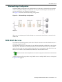
WDS WLAN Services ..................................................................................................................................... 5-3
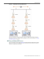
Key Features of WDS ..................................................................................................................................... 5-6
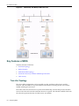
Tree-Like Topology .................................................................................................................................. 5-6
Radio Channels ........................................................................................................................................ 5-8
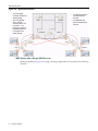
Multi-Root WDS Topology ........................................................................................................................ 5-8
Automatic Discovery of Parent and Backup Parent APs .......................................................................... 5-8
Link Security ............................................................................................................................................. 5-9
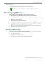
Before Configuring WDS Services ................................................................................................................. 5-9
Sketching the WDS Topology .................................................................................................................. 5-9
Configuring a WDS Service .......................................................................................................................... 5-10
Deploying the WDS ...................................................................................................................................... 5-12
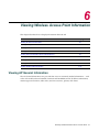
Chapter 6: Viewing Wireless Access Point Information
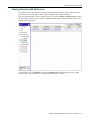
Viewing AP General Information .................................................................................................................... 6-1
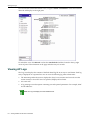
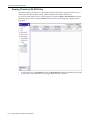
Viewing AP Logs ............................................................................................................................................ 6-2
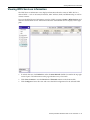
Viewing LAN Status Information ..................................................................................................................... 6-4
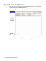
Viewing WLAN Radio Information .................................................................................................................. 6-5
Viewing General Information for a Radio ................................................................................................. 6-5
Viewing Statistics for a Radio ................................................................................................................... 6-6
Viewing General Information about a WLAN Service ..................................................................................... 6-7
Viewing General Information about a WLAN Policy ....................................................................................... 6-8
Viewing WLAN Clients Information ................................................................................................................. 6-9
Viewing All Clients .................................................................................................................................... 6-9
Viewing Clients by Radio ....................................................................................................................... 6-10
Viewing Clients by WLAN Service ......................................................................................................... 6-11
Viewing Clients by WLAN Policy ............................................................................................................ 6-12
Viewing WDS Services Information .............................................................................................................. 6-13
Viewing WLAN Cluster Information .............................................................................................................. 6-14
Appendix A: Troubleshooting
Rebooting the AP ...........................................................................................................................................A-1
Exporting and Importing Configuration ...........................................................................................................A-2
Restoring the AP to Factory Default Settings .................................................................................................A-4
LED Behavior .................................................................................................................................................A-5
LED Initialization Display ..........................................................................................................................A-5
Normal Mode LED Behavior ....................................................................................................................A-6
Identify Mode LED Behavior ....................................................................................................................A-6
WDS Signal Strength Mode LED Behavior ..............................................................................................A-7
vi
Chapter B: SNMP Traps and MIBs
SNMP Traps ...................................................................................................................................................B-1
SNMP MIBs ....................................................................................................................................................B-2
MIB-II (RFC1213) .....................................................................................................................................B-2
Policy MIB ................................................................................................................................................B-2
Appendix C: Regulatory Information
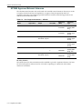
Wireless APs 3630 and 3640 .........................................................................................................................C-1
AP3640 External Antenna AP ..................................................................................................................C-1
United States ............................................................................................................................................C-1
Canada .....................................................................................................................................................C-4
European Community ..............................................................................................................................C-5
Certifications of Other Countries ............................................................................................................C-11
AP3640 Approved External Antennas ....................................................................................................C-12
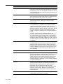
Appendix D: Glossary
Index
vii
viii
About This Guide
This guide describes how to configure and manage the Enterasys Wireless Standalone 802.11n AP.
For information about the CLI (Command Line Interface) set of commands used to configure and manage the AP, refer to the Enterasys Wireless Standalone 802.11n AP CLI Reference Guide.
Who Should Use This Guide
This guide is a reference for users and administrators who are responsible for configuring and managing the AP.
How to Use This Guide
Read through this guide completely to familiarize yourself with its contents and to gain an understanding of the features and capabilities of the AP. A general working knowledge of data communications networks and wireless networking is helpful when setting up the AP.
This preface provides an overview of this guide and a brief summary of each chapter; defines the conventions used in this document; and instructs how to obtain technical support from Enterasys Networks. To locate information about various subjects in this guide, refer to the following table:
For...
Refer to...
An overview of the AP and a list of features.
Chapter 1, Introduction
An introduction to networking concepts and an overview of
the AP’s management capabilities.
Chapter 2, Configuring Your Network
First time setup and basic configuration of the AP including,
how to log on to the user interface, downloading firmware,
changing passwords, and getting help.
Chapter 3, Getting Started with your
Enterasys Wireless Standalone 802.11n
AP
Procedures to configure the various capabilities of the AP.
Chapter 4, Configuring the Enterasys
Wireless Standalone 802.11n AP
An overview of Wireless Distribution Systems (WDS) and the
process to set up a WDS.
Chapter 5, Configuring WDS
Information about the various AP status views.
Chapter 6, Viewing Wireless Access
Point Information
A list of supported SNMP traps and MIBs.
Chapter B, SNMP Traps and MIBs
Troubleshooting information.
Appendix A, Troubleshooting
Regulatory information for the AP.
Appendix C, Regulatory Information
A list of commonly used terms and acronyms, and their
definitions.
Appendix D, Glossary
Enterasys Wireless Standalone 802.11n AP User Guide
ix
Related Documents
Related Documents
The manuals listed below can be obtained from the World Wide Web in Adobe Acrobat Portable Document Format (PDF) at the following site:
http://www.enterasys.com/support/manuals
•
Enterasys Wireless Standalone 802.11n AP Installation Instructions
•
Enterasys Wireless Standalone 802.11n AP CLI Reference Guide
Conventions Used in This Guide
The following conventions are used in the text of this document:
Convention
Description
Bold font
Indicates mandatory keywords, parameters or keyboard keys.
italic font
Indicates complete document titles.
Courier font
Used for examples of information displayed on the screen.
Courier font in italics
Indicates a user-supplied value, either required or optional.
[]
Square brackets indicate an optional value.
{}
Braces indicate required values. One or more values may be required.
|
A vertical bar indicates a choice in values.
[x | y | z]
Square brackets with a vertical bar indicates a choice of a value.
{x | y | z}
Braces with a vertical bar indicate a choice of a required value.
[x {y | z} ]
A combination of square brackets with braces and vertical bars indicates a
required choice of an optional value.
The following icons are used in this guide:
Note: Calls the reader’s attention to any item of information that may be of special importance.
Caution: Contains information essential to avoid damage to the equipment.
Precaución: Contiene información esencial para prevenir dañar el equipo.
Achtung: Verweißt auf wichtige Informationen zum Schutz gegen Beschädigungen.
x
About This Guide
Getting Help
Getting Help
For additional support related to the AP or this document, contact Enterasys Networks using one of the following methods:
World Wide Web
www.enterasys.com/services/support/
Phone
1-800-872-8440 (toll-free in U.S. and Canada)
or 1-978-684-1000
For the Enterasys Networks Support toll-free number in your country:
www.enterasys.com/services/support/contact/
Internet mail
[email protected]
To expedite your message, please type [Wireless] in the subject line.
To send comments or suggestions concerning this document to the Technical Publications Department:
[email protected]
To expedite your message, include the document Part Number in the Email message.
Before contacting Enterasys Networks for technical support, have the following data ready:
•
Your Enterasys Networks service contract number
•
A description of the failure
•
A description of any action(s) already taken to resolve the problem (for example, changing mode switches or rebooting the unit)
•
The serial and revision numbers of all involved Enterasys Networks products in the network
•
A description of your network environment (such as layout, cable type, other relevant environmental information)
•
Network load and frame size at the time of trouble (if known)
•
The device history (for example, if you have returned the device before, or if this is a recurring problem)
•
Any previous Return Material Authorization (RMA) numbers
Enterasys Wireless Standalone 802.11n AP User Guide
xi
Getting Help
xii
About This Guide
1
Introduction
This chapter introduces the Enterasys Wireless Standalone 802.11n Access Point (AP) and provides an overview of the AP’s applications, features, and policy. Standalone AP Overview
Refer to page...
About the Enterasys Wireless Standalone 802.11n AP
1-1
Applications
1-2
Features
1-2
About the Enterasys Wireless Standalone 802.11n AP
The Enterasys Wireless Standalone 802.11n AP provides secure, highly scalable, wireless high‐
speed data communication between the wired LAN and fixed or mobile devices equipped with an 802.11a, 802.11b, 802.11g, and/or 802.11n wireless adapter. This solution offers fast, reliable wireless connectivity with considerable cost savings over wired LANs (which include long‐term maintenance overhead for cabling).
The Enterasys Wireless Standalone 802.11n AP is an IEEE 802.11n‐compliant access point that offers significant increase in data throughput and coverage range without additional bandwidth or transmit power. With both 2.4 GHz and 5 GHz 802.11n standard radio modules, the AP delivers total data rates of up to 300 Mbps. Given that the improved throughput of 300 Mbps will be spread over a number of simultaneous users, the performance of the AP will be close to that of a wired 100 Mbps Ethernet connection — the standard for desktop connectivity. With the Enterasys Wireless Standalone 802.11n AP, mobile users get a similar experience to wired networks while accessing high‐bandwidth data, voice, and video applications. The Enterasys Wireless Standalone 802.11n AP is a cost‐effective solution that is both easy to manage and easy to deploy.
The AP supports up to eight virtual access points (VAP) per physical radio interface: eight on the 802.11a/n radio and eight on the 802.11b/g/n radio. For each VAP, you can apply different security settings, VLAN assignments, and other parameters. Each radio interface on the AP can operate in one of three ways:
•
Access Point – Providing connectivity to wireless clients in the service area.
•
Bridge (Point‐to‐Point) – Providing links to other access points in “Bridge” or “Root AP” mode connecting wired LAN segments.
•
Root AP (Point‐to‐Multipoint) – Providing links to other access points in “Bridge” mode connecting wired LAN segments. In addition, the AP offers full network management capabilities through an easy to configure web interface, a command line interface for initial configuration and troubleshooting, and support for Simple Network Management (SNMP) tools.
Enterasys Wireless Standalone 802.11n AP User Guide
1-1
Applications
Applications
The Enterasys Wireless Standalone 802.11n AP offers a high speed, reliable, cost‐effective solution for wireless client access to the network in environments such as:
•
Remote access to corporate network information
•
Difficult‐to‐wire environments •
Frequently changing environments
•
Retailers, manufacturers, and banks that frequently rearrange the workplace or change location
•
Temporary LANs for special projects or peak times
•
Auditors who require workgroups at customer sites
•
Access to databases for mobile workers, for example: doctors, nurses, retailers, or white‐collar workers who need access to databases while being mobile in a hospital, retail store, or an office campus
Features
The Enterasys Wireless Standalone 802.11n AP provides the following features:
Standalone solution AP for the Small to Medium Enterprise (SME) market
•
End‐to‐end solution for wireless real‐time IP communication and integration
•
Best‐in‐class voice quality, multimedia enabled
•
Automatic channel selection
•
Seamless roaming within the IEEE 802.11a/b/g/n WLAN environment
•
(AP 3640 only) Three external antenna connectors for use with both indoor and outdoor antennas
Ease of management
•
Manageable through secure web management, CLI interface, and SNMP
•
Support for advanced manageability through Enterasys NetSight Console and NetSight Inventory Manager
Standards compliance
1-2
Introduction
•
Strong SME level security, supporting WEP, WPAv1, and WPAv2
•
IEEE 802.11a, 802.11b, 802.11g, and 802.11n compliance
•
Backward compatible with existing 802.11a/b/g networks
2
Configuring Your Network
Proper configuration of a wireless network requires an understanding of the AP’s components and security features. The following sections discuss some network options focused around the use of the Enterasys Wireless Standalone 802.11n AP. The AP’s network management, security, and authentication abilities are also discussed.
For information about...
Refer to page...
Wireless Networking Concepts
2-1
About Clustering
2-4
RADIUS Authentication
2-5
About Network Security
2-5
About Quality of Service
2-6
Wireless Networking Concepts
Wireless communication between two or more computers requires that each computer be equipped with a receiver/transmitter—a WLAN network adapter—capable of exchanging digital information over a common radio frequency. This setup is called an ad hoc configuration. An ad hoc network allows wireless devices to communicate with each other using an Independent Basic Service Set (IBSS).
An alternative to an ad hoc configuration is the use of an AP. Computers and other wireless devices communicate with each other through the AP. The IEEE 802.11 standard defines an AP as a device that allows other wireless devices to communicate with a distribution system using a Basic Service Set (BSS) or an infrastructure network.
For the wireless devices to communicate with computers on a wired network, the APs must be connected into the wired network, and provide access to the networked computers. This is called bridging. Infrastructure Wireless LAN
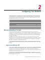
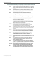
The AP provides wireless workstations with access to a wired LAN. An integrated wired/wireless LAN is called an infrastructure configuration. A BSS consists of a group of wireless PC users, and an AP that directly connects to the wired LAN. Each wireless PC in this BSS can talk to any computer in its wireless group via a radio link, or access other computers or network resources in the wired LAN infrastructure via the AP.
The infrastructure configuration not only extends the accessibility of wireless PCs to the wired LAN, but also increases the effective wireless transmission range for wireless PCs by passing their signal through one or more APs.
Enterasys Wireless Standalone 802.11n AP User Guide
2-1
Wireless Networking Concepts
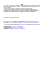
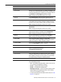
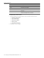
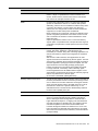
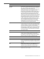
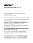
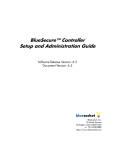
A wireless infrastructure can be used for access to a central database, or for connection between mobile workers, as shown in Figure 2‐1.
Figure 2-1
Infrastructure Wireless LAN
Infrastructure Wireless LAN for Roaming Wireless PCs
The BSS defines the communications domain for each AP and its associated wireless clients. The BSS ID is a 48‐bit binary number based on the AP’s wireless MAC address, and is set automatically and transparently as clients associate with the AP. The BSS ID is used in frames sent between the AP and its clients to identify traffic in the service area. The BSS ID is only set by the AP, never by its clients. The clients only need to set the Service Set Identifier (SSID) that identifies the service set provided by one or more APs. The SSID can be manually configured by the clients, can be detected in an AP’s beacon, or can be obtained by querying for the identity of the nearest AP. For clients that do not need to roam, set the SSID for the wireless device to that used by the AP to which you want to connect.
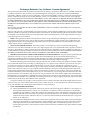
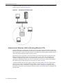
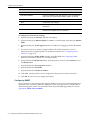
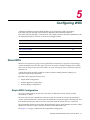
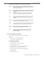
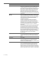
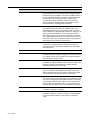
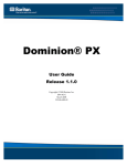
A wireless infrastructure can also support roaming for mobile workers. You can configure more than one AP to create an Extended Service Set (ESS), as shown in Figure 2‐2 on page 2‐3. By placing the APs so that a continuous coverage area is created, wireless users within this ESS can roam freely. All wireless network adapters and APs within a specific ESS must be configured with the same SSID.
2-2
Configuring Your Network
Wireless Networking Concepts
Figure 2-2
Infrastructure Wireless LAN for Roaming
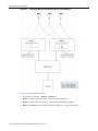
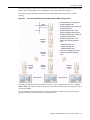
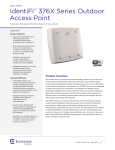
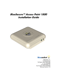
Infrastructure Wireless Bridge
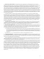
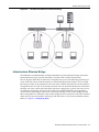
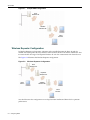
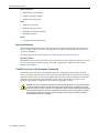
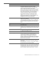
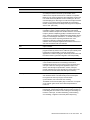
The IEEE 802.11 standard defines a Wireless Distribution System (WDS) for bridge connections between BSS areas (APs). The AP uses WDS to forward traffic on links between units. The AP supports WDS links on either the 5 GHz (802.11a/n) or 2.4 GHz (802.11b/g/n) bands and can be used with various external antennas to offer flexible deployment options. Up to 12 WDS links (six per radio) can be specified for each unit in the wireless network. Only one unit must be configured as the “root AP” in the wireless network. The root AP should be the unit connected to the main core of the wired LAN. Other WDS APs must configure one “parent” link to the root or to a WDS AP connected to the root AP. The other five available WDS links can be specified as “child” links to other bridges. This forms a tiered‐star topology for the wireless bridge network. When using WDS on a radio band, only wireless bridge units can associate to each other. Wireless clients can only associate with the AP using a radio band set to AP. For more information about WDS, see Chapter 5, Configuring WDS.
Enterasys Wireless Standalone 802.11n AP User Guide
2-3
About Clustering
Figure 2-3
Infrastructure Wireless Bridge
Network
Core
802.11 b/g/n
Radio AP
Link
Bridge AP
Root AP
802.11 b/g/n
Radio AP
Link
802.11 a/n
Radio Bridge
Link
802.11 b/g/n
Radio AP
Link
Bridge AP
Bridge AP
About Clustering
The AP can operate in a cluster setup. A cluster is a group of wireless APs configured to communicate with each other. Mobile users (MU) can seamlessly roam between the APs participating in the cluster. The Enterasys Wireless Standalone 802.11n AP extends basic cluster functionality with the following enhancements:
2-4
•
Support for fast roaming •
Automatic Channel Selection (ACS) for all APs in the cluster
•
Cluster member information is available to the user
Configuring Your Network
RADIUS Authentication
•
MU statistic history •
Pre‐authentication
A cluster forms when APs operating within the same subnet are configured with the same cluster ID (shared secret). A cluster AP can exist at any point in your network. Each cluster member periodically (30 seconds) sends a secure SIAPP multicast message to update other cluster members. The SIAPP message includes:
•
The AP Name
•
The AP Ethernet MAC address
•
The AP IP address
•
The client count
•
The base BSSIDs for both radios
Each AP caches locally information about other cluster members and maintains its own view of the cluster. For more information about configuring a cluster, see “Configuring General LAN Settings” on page 4‐2. RADIUS Authentication
Remote Authentication Dial‐in User Service (RADIUS) is an authentication protocol that uses software running on a central server to control access to RADIUS‐aware devices on the network. An authentication server contains a database of user credentials for each user that requires access to the network.
You must specify a primary RADIUS server for the AP to implement IEEE 802.1x network access control and Wi‐Fi Protected Access (WPA) wireless security. You can also specify a secondary RADIUS server as a backup should the primary server fail or become inaccessible.
In addition, the configured RADIUS server can also act as a RADIUS accounting server and receive user‐session accounting information from the access point. RADIUS accounting can be used to provide valuable information on user activity in the network.
Notes: This guide assumes that you already configured RADIUS server(s) to support the access
point. Configuration of RADIUS server software is beyond the scope of this guide. Refer to the
documentation provided with the RADIUS server software.
If you are using RADIUS, it is highly recommended that you assign the AP a static IP address to
ensure that the address doesn’t change via DHCP.
For information about RADIUS configuration, see “Configuring RADIUS Authentication” on page 4‐10.
About Network Security
The AP provides features and functionality to control network access. These are based on standard wireless network security practices. Current wireless network security methods provide a degree of protection. These methods include an open system that relies on SSIDs.
The AP supports the following encryption approaches:
•
Wired Equivalent Privacy (WEP) – A security protocol for wireless local area networks defined in the IEEE 802.11b standard that provides static key management, and WEP 64‐bit, 128‐bit, and 152‐bit ciphers.
Enterasys Wireless Standalone 802.11n AP User Guide
2-5
About Quality of Service
•
Wi‐Fi Protected Access version 1 (WPA v.1) – A security protocol with Temporal Key Integrity Protocol (TKIP) that provides pre‐shared Master Key management, and a WEP 128‐bit cipher.
•
Wi‐Fi Protected Access version 2 (WPA v.2) – A security protocol with Advanced Encryption Standard (AES) that provides pre‐shared Master Key management, and an AES 128‐bit cipher.
About Quality of Service
The AP provides advanced Quality of Service (QoS) management in order to provide better network traffic flow. Such features include:
2-6
•
WMM (Wi‐Fi Multimedia) — Enabled globally on the AP. For devices with WMM enabled, the standard provides multimedia enhancements for audio, video, and voice applications. WMM shortens the time between transmitting packets for higher priority traffic. •
IP ToS (Type of Service) or DSCP (Diffserve Codepoint) — The ToS/DSCP field in the IP header of a frame indicates the priority and QoS for each frame.
•
Pre‐WMM — The AP also supports legacy QoS management such as 802.11e, flexible client access, and voice and video admission control.
Configuring Your Network
3
Getting Started with your Enterasys Wireless
Standalone 802.11n AP
Before you can begin using the AP, you must complete some preliminary steps. This section discusses the initial process of starting the AP, accessing the interface, and first time configuration. For information about...
Refer to page...
Powering the AP
3-1
IP Address Assignment and Acquisition
3-2
Managing the AP
3-3
Understanding the Browser Interface
3-5
Configuring the Standalone AP for the First Time
3-9
Powering the AP
You can connect the AP to the wired LAN and provide power to the AP in one of three ways: •
Power over Ethernet (PoE) – If your network is already set up with PoE, attach the LAN Ethernet cable to the RJ45 Ethernet connector at the bottom of the AP. For this method you can use a regular Ethernet cable.
•
Power over Ethernet: Adding a PoE injector – If your network is not set up with PoE, you can provide power to the LAN Ethernet cable with a PoE injector. The PoE injector must be 802.3af compliant. The PoE injector is not provided with the AP. If you are using a PoE injector, refer to the manufacturer’s documentation for the necessary requirements.
•
Power by AC adaptor – An AC adaptor is available for purchase from Enterasys Networks, but not included with the AP. For more information about the AC adaptor, contact your Enterasys sales representative. If you are using a direct connection to the AP you can use either a straight‐through or cross‐
over Ethernet cable.
After connecting the AP to the wired LAN and applying power, the AP begins the initialization process. For more information about installing and powering your AP, see the Enterasys Wireless Standalone 802.11n AP Installation Instructions. Enterasys Wireless Standalone 802.11n AP User Guide
3-1
IP Address Assignment and Acquisition
IP Address Assignment and Acquisition
The APs are shipped from the factory with a default IP address — 192.168.1.20. The default IP address simplifies the first‐time IP address configuration process for APs. If the AP fails to acquire an IP address through DHCP, it returns to its default IP address. This behavior ensures that only one AP at a time can use the default IP address on a subnet. When the AP is powered‐on, the following occurs: 1.
The AP attempts to reach the DHCP server on the network to acquire the IP address. If the AP is successful in reaching the DHCP server, the DHCP server assigns an IP address to the AP. 2.
If the DHCP assignment is not successful in the first 60 seconds, the AP returns to its default IP address.
3.
The AP waits for 30 seconds in default IP address mode before again attempting to acquire an IP address from the DHCP server. 4.
The process repeats itself until the DHCP assignment is successful, or until an administrator assigns the AP an IP address, using static configuration.
Notes: DCHP assignment is the default method for the AP configuration. DHCP assignment is part
of the initialization process.
You can establish a SSH session with the AP during the time window of 30 seconds when the AP
returns to its default IP address mode. If a static IP address is assigned during this period, you must
reboot the AP for the configuration to take effect.
Discovering DHCP Assigned IP Addresses
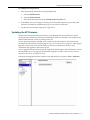
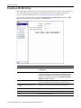
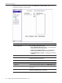
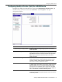
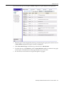
To access an AP’s management interface, you must know the IP address of the AP. By default the AP tries to obtain its IP address from a DHCP server. To determine the IP addresses assigned to the APs within a domain, Enterasys provides the AP Discovery Tool for download. The AP Discovery Tool is a Java‐based application designed to help keep track of the deployed APs and retrieve their assigned IP addresses. The AP Discovery Tool discovers and lists the APs in the current multicast domain. The AP Discovery Tool can be run on any platform with Java Runtime Environment (JRE 6 update 18 and higher) installed. To discover DHCP assigned IP addresses:
1.
Download the AP Discovery Tool (ApDiscovery.jar) from the Enterasys support site, in the Downloads section, under Firmware & Software, and save locally.
Note: The workstation must be in the same multicast network domain as the deployed APs.
2.
Open a command prompt. Navigate to the directory to which you saved the ApDiscovery.jar file. 3.
Run the following command:
java -jar ApDiscovery.jar
The AP Discovery Tool scans the multicast domain and displays the results of the search, as shown below. 3-2
Getting Started with your Enterasys Wireless Standalone 802.11n AP
Managing the AP
############################ 2010-04-06 14:33:18 ##########################
IP Address
Cluster
MAC Address
AP Name
192.168.7.252
1
00:1A:E8:14:22:D0
N/A
192.168.7.176
1
00:1A:E8:14:10:BA
N/A
192.168.7.236
2
00:12:CF:73:70:3D
00000012CF73702D
192.168.7.254
1
00:1A:E8:14:10:7D
N/A
192.168.7.173
1
00:1A:E8:14:11:B9
N/A
192.168.7.174
2
00:1A:E8:14:10:63
0000001261737111
############################# 2010-04-06 14:33:50 ##########################
IP Address
Cluster
MAC Address
AP Name
192.168.7.254
1
00:1A:E8:14:10:7D
N/A
192.168.7.252
1
00:1A:E8:14:22:D0
N/A
192.168.7.176
1
00:1A:E8:14:10:BA
N/A
192.168.7.173
1
00:1A:E8:14:11:B9
N/A
192.168.7.236
2
00:12:CF:73:70:3D
0000001234737023
192.168.7.174
2
00:1A:E8:14:10:63
0000001261737111
The information displayed in the output is as follows:
–
IP Address ‐ The IP address of the discovered AP.
–
Cluster ‐ If the deployed APs are configured into different clusters, this field allows the operator to find out which APs are in the same cluster. In the above example, there are 2 clusters. –
MAC Address ‐ The MAC address of the AP.
–
AP Name ‐ The name of the AP. The default value is the AP’s serial number.
Note: The AP Name field is populated for APs not using Cluster Encryption or the default Cluster
Shared Secret (ThisIsDefaultClusterPassword). If you have changed the Cluster Shared Secret,
you can resolve the AP Name by running the following command:
java -jar ApDiscovery.jar -s <modified cluster shared secret>
For the full list of AP Discovery Tool commands, launch the help by running the following command:
java -jar ApDiscovery.jar -h
4.
To determine the IP address of a particular AP, first locate the serial number on a label affixed to the AP you that want to configure. Match that serial number with the serial number listed under the AP Name column in the Discovery Tool output. The IP address in the Discovery Tool output that corresponds to the AP serial number is assigned to that AP. Managing the AP
The Enterasys Wireless Standalone 802.11n AP provides you with multiple management options. You can manage the Enterasys Wireless Standalone 802.11n AP with:
•
The Command Line Interface (CLI) accessed through a direct connection to the console port (115kbps, 8 bit no parity) or through a Secure SHell (SSH) connection. For more information about how to use the CLI, and command descriptions, refer to the Enterasys Wireless Standalone 802.11n AP CLI Reference Guide.
Enterasys Wireless Standalone 802.11n AP User Guide
3-3
Managing the AP
•
•
The secured web interface accessed through a web browser (the focus of this guide). The AP supports the following web browsers:
–
Internet Explorer v7.0 and 8.0
–
Firefox v3.4 and 3.5 An SNMP manager, such as Enterasys Networks NetSight management applications. For information about configuring SNMP management, see “Configuring SNMP” on page 4‐4.
Accessing and Logging-in to the Web-Based Interface
This section discusses the procedure to access the web‐based interface through a supported Web browser. Up to five client sessions can be open at one time. To access the AP, you must log on using a valid user ID and password. The default user name and password are:
User Name: admin
Password: new2day
By default, the AP is DHCP‐enabled. To log on, use the IP address according to your network DHCP IP address assignment. If the AP cannot get an IP address by DHCP, use the default 192.168.1.20 IP address. For more information, see “IP Address Assignment and Acquisition” on page 3‐2.
To display the login screen, type the following in a Web browser:
https://<static or DHCP-provided IP address>
Field
3-4
Description
User Name
Enter admin.
Password
Enter the Password. The default password is new2day.
Getting Started with your Enterasys Wireless Standalone 802.11n AP
Understanding the Browser Interface
To log in to the AP:
Enter the User Name and Password, then click Login. You are now logged‐in to the AP as an administrator. Notes: Enterasys Networks strongly recommends that you change your password the first time you
log in.
The Web session will time out after 60 minutes (1 hour) of non-activity.
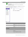
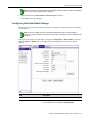
Understanding the Browser Interface
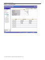
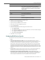
The browser interface provides a way to configure, manage, and monitor the standalone AP. You navigate through the browser interface as you would a typical web page. You use the navigation tree in the left pane to move among pages within the user interface. You can click a link to get details about a selected item. Each page has four distinct sections:
•
Top user interface banner •
Bottom user interface banner
•
Navigation tree in the left‐hand pane
•
User interface page content area in the right‐hand pane
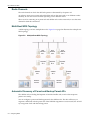
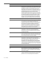
Figure 3‐1 shows a Standalone AP user interface page.
Enterasys Wireless Standalone 802.11n AP User Guide
3-5
Understanding the Browser Interface
Figure 3-1
3-6
User Interface Page
Getting Started with your Enterasys Wireless Standalone 802.11n AP
Understanding the Browser Interface
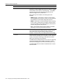
Understanding the Page Banners
The banner that displays across the top of each page provides general AP information and links to display online help and to logout from the user interface. Figure 3‐2 shows the contents of the top banner.
Figure 3-2
Top Banner of the Standalone AP User Interface
Table 3‐1 describes the contents of the top banner.
Table 3-1
Contents of the Top Banner
Field/Link
Description
Wireless Access Point <model_name>
Displays the model name of the AP managed by the standalone
AP user interface. The UI retrieves the model name from the AP
firmware. Options include:
• AP3640-ROW — an 802.11 AP with external antennas. This
AP is certified to operate in areas other than North America.
• AP3640-NAM — an 802.11 AP with external antennas. This
AP is certified to operate only in North America.
• AP3630-ROW — an 802.11 AP with internal antennas. This
AP is certified to operate in areas other than North America.
• AP3630-NAM — an 802.11 AP with internal antennas. This
AP is certified to operate only in North America.
<path_name>
Displays the path used to access the page that is displayed in
the right hand page content.
Help
Click to navigate to the Enterasys Networks Hardware and
Software Manuals page in a new Web browser window.
Logout
Ends the session with the standalone AP user interface. Clicking
this link returns you to the login screen.
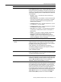
The banner that displays across the bottom of each page provides information about the AP that you are managing. Figure 3‐3 shows the contents of the bottom banner.
Figure 3-3
Standalone AP Bottom Banner
Table 3‐2 describes the contents of the bottom banner.
Table 3-2
Contents of the Bottom Banner
Field/Link
Description
AP Name
Displays the name assigned to the standalone AP.
User
Displays the name of the user logged into the Standalone AP
user interface.
Address
Displays the IP address assigned to the standalone AP.
Firmware
Displays the firmware version running on the AP.
Enterasys Wireless Standalone 802.11n AP User Guide
3-7
Understanding the Browser Interface
Table 3-2
Contents of the Bottom Banner (continued)
Field/Link
Description
BootROM
Displays the BootROM version of the AP.
WDS uplink
Displays only for child APs that participate in a WDS.
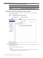
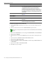
Navigating Through the Standalone AP User Interface
The main user interface window contains both a navigation tree in the left pane and a page content area in the right pane. Figure 3-4
Navigation Pane and Page Content Area
Navigation Pane
Page Content Area
Using the Navigation Tree
The navigation tree displays in the left pane of the interface. You use the navigation tree to move among folders and pages. The top level folders in the navigation pane are:
•
Status
Expanding the Status link provides a listing of all folders and pages from which you can monitor AP behavior or view AP configuration settings. 3-8
Getting Started with your Enterasys Wireless Standalone 802.11n AP
Configuring the Standalone AP for the First Time
•
Configuration Expanding the Configuration link provides a listing of all folders and pages from which you can configure AP behavior and settings. •
Tools
Expanding the Tools link provides a listing of all folders and pages from which you can manage configuration files and users, perform firmware upgrades, and troubleshoot or reboot the AP.
When a plus sign (+) displays next to an item in the navigation tree, that item is not an active link; you must click the plus sign to expand the display. Conversely, you must click the minus sign (‐) to collapse the display. The top‐level folders (Status, Configuration, and Tools) collapse only when you expand a different top‐level folder.
Clicking on an active link produces the following results:
•
The active link is highlighted in blue.
•
The content of right‐hand page refreshes.
You can expand and collapse items in the navigation tree without affecting the page content area displayed in the right pane; the right pane display changes only when you click another active link in the navigation tree. Note: If you collapse and later expand the section containing the link to the current page displayed
in the right pane, the blue highlighting no longer applies to the link. The top UI banner, however,
displays the path to the right pane.
Using the Content Page
The content section of each page displays AP information as a form or table. You click a link in the page, or enter information in a field, to perform a task or to move among pages. You can also move among pages by clicking an object in the navigation tree.
Configuring the Standalone AP for the First Time
When the AP powers‐up for the first time, for the AP to be operational and able to transfer data, at a minimum you must configure or verify the following settings:
•
Password
•
IP address
•
Firmware version
•
At lease one WLAN policy •
At least one WLAN service •
Radios
After configuring these settings the AP will have one working WLAN service, will advertise the SSID, and wireless clients should be able to connect to the AP with no encryption. At a later time you can fine tune the AP’s configuration as described in Chapter 4, Configuring the Enterasys Wireless Standalone 802.11n AP. The following sections describe the basic configuration settings required for the AP to be fully operational. Enterasys Wireless Standalone 802.11n AP User Guide
3-9
Configuring the Standalone AP for the First Time
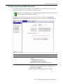
Changing the Password
The admin account on the standalone AP comes with the factory default password new2day. Enterasys Networks recommends changing the password the first time you log on and regularly thereafter.
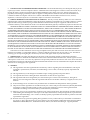
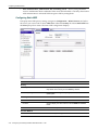
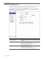
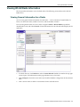
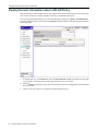
To display the password settings, navigate to Tools > Users > admin. The user management settings display in the right pane. Field
3-10
Description
User Name
Identifies the user account. The default is admin.
Old Password
Enter the password currently in use. The default is new2day.
New Password
Enter the new password for the AP. The new password must be
between six and thirty-two alphanumeric and special characters,
except ‘”’:\ and the space character. The password is casesensitive.
Confirm New Password
Re-enter the new password.
Save
Click to save the new password.
Getting Started with your Enterasys Wireless Standalone 802.11n AP
Configuring the Standalone AP for the First Time
To configure the AP password:
1.
Enter the following information in the specified fields: a.
Enter the Old Password.
b.
Enter the New Password.
c.
Re‐enter the new password in the Confirm New Password field. 2.
Click Save to save your changes. The new password entered replaces the previously used password. The software automatically logs you out of the user interface.
3.
Log into the user interface using the new password.
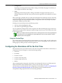
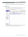
Updating the AP Firmware
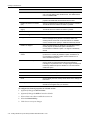
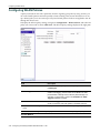
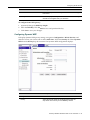
The banner at the bottom of the user interface screen identifies the current firmware version running on the AP. Enterasys Networks periodically provides new firmware. You should ensure that the latest firmware version is running on the AP. To view the latest firmware available, open a web browser and navigate to the firmware and software link of the Enterasys support page at: http://www.enterasys.com/support/. If the support page lists a more recent version of firmware for the AP, you should save the file to your workstation and upgrade to the newest version. You can upgrade the AP firmware from the Upgrade Firmware page in the Web interface or from the standalone AP CLI. To upgrade the firmware using the CLI, refer to the Enterasys Wireless Standalone 802.11n AP CLI Reference Guide. To display the Upgrade Firmware window in the Web interface, navigate to Tools > Firmware. Enterasys Wireless Standalone 802.11n AP User Guide
3-11
Configuring the Standalone AP for the First Time
Field
Description
Upgrade Firmware
File
Enter the filename and location of the firmware image to install or
click Browse to navigate to the file.
Browse
Click to browse for the location of the firmware file to install.
Download and Reboot
Click to download the firmware image from the location specified
in the File field. Clicking this button causes the AP to reboot.
To update the AP firmware:
1.
Click Browse to open a navigation window. 2.
Select the firmware file and click Open. 3.
Click Download and Reboot. The AP prompts you that this action will cause the AP to reboot. 4.
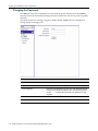
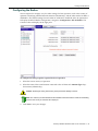
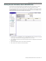
Click OK. The AP reboots to implement the new code. Configuring the IP Address
By default, DHCP is enabled on the AP and assigns a unique IP address to the AP. If the DHCP server is not available or if you disable DHCP, the AP uses the default IP address (192.168.1.20). If you are using the default IP address, you must change it because only one AP at a time can use the default IP address. Note: If you are using RADIUS authentication, it is highly recommended that you assign the AP a
static IP address to ensure that the address doesn’t change via DHCP.
3-12
Getting Started with your Enterasys Wireless Standalone 802.11n AP
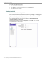
Configuring the Standalone AP for the First Time
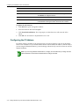
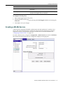
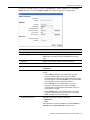
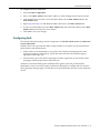
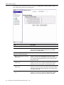
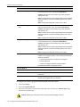
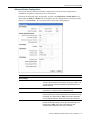
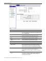
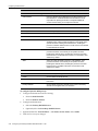
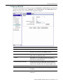
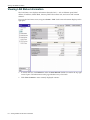
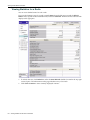
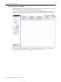
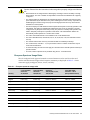
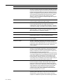
To display the IP address settings, navigate to Configuration > LAN > General. The General LAN configuration settings display in the right pane.
Field
Description
General
AP Name
Enter a unique name that identifies the AP. The default value is
the AP’s serial number.
AP Contact/Description
Enter a brief description that helps identify the access point.
Ethernet Port
Ethernet Speed
Select the Ethernet Speed from the drop-down menu. Your
options include:
• Auto (Default)
• 10Mbps
• 100Mbps
Ethernet Mode
Select either Half-duplex or Full-duplex (default) from the dropdown menu. This drop-down menu is not available when
Ethernet Speed is set to Auto.
Enterasys Wireless Standalone 802.11n AP User Guide
3-13
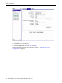
Configuring the Standalone AP for the First Time
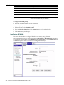
Field
Description
Management
VLAN Tagged
Select to use VLAN tagging. When you enable VLAN tagging, the
AP inserts the VLAN ID in the data packet header to identify which
VLAN the packet belongs to. If selected, you must enter a value in
the VLAN ID field. VLAN Tagged is disabled by default.
Note: Changing this setting will cause the AP to reboot.
VLAN ID
If the VLAN Tagged checkbox is selected, enter the ID of the
VLAN on which the AP will operate. The default value is 1.
Dynamic IP (DHCP)
Select to enable/deselect to disable DHCP. Select this checkbox
for the DHCP server to assign a dynamic IP address to the AP.
Deselect to use a static IP address. DHCP is enabled by default.
Note: Changing this setting will cause the AP to reboot.
IP Address
Enter the static IP address of the AP. The default IP address is
192.168.1.20.
Note: Changing this setting will cause the AP to reboot.
Subnet Mask
Enter the subnet mask of the AP. The Subnet Mask is entered in
dotted, decimal notation. The default value is 255.255.255.0.
Note: Changing this setting will cause the AP to reboot.
Gateway
Enter the default gateway. The default value is 192.168.1.1.
Note: Changing this setting will cause the AP to reboot.
Enable SNMP
Select to enable/deselect to disable SNMP communication. When
Enable SNMP is selected, the Configure SNMP button displays.
SNMP is disabled by default.
Configure SNMP
Click to view and edit SNMP settings. This button is available only
when the Enable SNMP checkbox is selected.
Cluster
3-14
Shared Secret
Enter the common password that authenticates members of the
cluster. The default shared secret is
ThisIsDefaultClusterPassword.
Unmask
Click to display the value entered in the Shared Secret field.
Use Encryption
Select to enable/deselect to disable encryption. When enabled,
message exchange between the APs in the cluster is encrypted.
When disabled, messages are sent in plain text, which is useful
for troubleshooting. Encryption is enabled by default.
Getting Started with your Enterasys Wireless Standalone 802.11n AP
Configuring the Standalone AP for the First Time
Field
Description
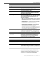
LED
LED Mode
Select the LED Mode from the drop-down menu. You can select
one of the following modes:
• Off — Only displays LED fault patterns. LEDs are off when the
AP is fault free and initialization is finished.
• Normal — (default) LEDs function normally.
• Identify — All LEDs blink simultaneously.
• WDS Signal Strength — LEDs are used to indicate the WDS
signal strength as a bar-graph (VU-meter). Use this setting
only if the AP participates in a WDS.
• For more information about the different LED modes, see “LED
Behavior” on page A-5.
Network Time Protocol (NTP)
NTP Server Address
Enter the IP address of the NTP Server. If you do not identify an
NTP server, the logs timestamp displays “uptime” for the AP.
Function Buttons
Save
Click to save your changes.
Undo
Click to display the most recently saved values for the settings on
this screen.
Factory Defaults
Click to display the factory defaults on this screen.The factory
defaults are not applied until you click Save.
To configure the IP address settings:
1.
Locate the settings in the Management section of the page.
2.
(Optional) Deselect the Dynamic IP (DHCP) checkbox to configure a static IP address.
3.
Change the IP Address.
4.
(Optional) Change the Subnet Mask.
5.
(Optional) Change the Gateway.
6.
Click Save to save your changes. Enterasys Wireless Standalone 802.11n AP User Guide
3-15
Creating a WLAN Policy
Creating a WLAN Policy
This section discusses how to set up a WLAN policy. You must create at lease one WLAN policy for the AP to be operational and able to transfer data. Policies are applied through WLAN services. For more information, see “Configuring WLAN Policies” on page 4‐28.
To create a new WLAN policy, navigate to Configuration > WLAN Policies, and select <Add New>. The WLAN policy settings display in the right pane.
Field
Description
Policy Name
Enter a name for the policy. The default policy name is
newPolicy00.
VLAN Tagged
Select to enable/deselect to disable VLAN tagging. When you
enable VLAN tagging, the AP inserts the VLAN ID in the data
packet header to identify which VLAN the packet belongs to. If
selected, you must enter a value in the VLAN ID field. VLAN
Tagged is disabled by default.
VLAN ID
If the VLAN Tagged checkbox is selected, enter the ID of the
VLAN on which the policy will operate. The default value is 1.
Number of Services Using This
Policy
Displays the number of services currently using this policy.
Number of Clients Using This Policy Displays the number of clients currently using this policy.
Function Buttons
3-16
Save
Click to save your changes.
Delete
Click to delete the WLAN policy.
Getting Started with your Enterasys Wireless Standalone 802.11n AP
Creating a WLAN Service
Field
Description
Undo
Click to display the most recently saved values for the settings on
this screen.
Factory Defaults
Click to display the factory defaults on this screen.The factory
defaults are not applied until you click Save.
To configure a WLAN policy:
1.
Enter a meaningful name for the policy.
2.
(Optional) Enable VLAN tagging by selecting the VLAN Tagged checkbox and entering the VLAN ID.
3.
Click Save to save your changes. Creating a WLAN Service
A WLAN service represents all the RF, authentication and QoS attributes of a wireless access service. This section describes how to create a WLAN service and configure basic properties, required for the AP to be operational and able to transfer data. For more information, see “Configuring WLAN Services” on page 4‐29.
To create a WLAN service, navigate to Configuration > WLAN Services, and select <Add New>. The General tab of the WLAN services configuration displays in the right pane.
Enterasys Wireless Standalone 802.11n AP User Guide
3-17
Creating a WLAN Service
Field
Description
Service Name
Enter the name of the WLAN service. You can change this field
only if you are adding a new WLAN service. The default service
name is newService00.
SSID
Enter the SSID of the WLAN service. The software automatically
populates the SSID field with the default service name.
Enable This Service on Radio 1
(a/n)
Select to enable/deselect to disable the WLAN service on Radio 1.
The WLAN service is enabled on Radio 1 by default.
Enable This Service on Radio 2
(b/g/n)
Select to enable/deselect to disable the WLAN service on Radio 2.
The WLAN service is enabled on Radio 2 by default.
Default Policy
Select a policy as the default for this WLAN service.
Advanced Settings
Suppress SSID
Select to prevent/deselect to allow this SSID from appearing in the
beacon message sent by the AP. The wireless device user
seeking network access will not see this SSID as an available
choice, and will need to specify it. SSIDs are allowed by default.
Enable 11h Support
Select to enable/deselect to disable TPC (Transmission Power
Control) reports. By default this option is disabled. It is
recommended to enable this option. 11h support is disabled by
default.
Apply Power Reduction to 11h
Clients
Select to enable/deselect to disable the AP to use reduced power
(as does the 11h client). By default this option is disabled. It is
recommended to enable this option. Power reduction to 11h
clients is disabled by default.
Process Client IE Requests
Select to enable/deselect to disable the AP to accept IE requests
sent by clients via Probe Request frames and responds by
including the requested IE’s in the corresponding Probe Response
frames. By default this option is disabled. It is recommended to
enable this option.
Function Buttons
Save
Click to save your changes.
Delete
Click to delete the WLAN service.
Undo
Click to display the most recently saved values for the settings on
this screen.
Factory Defaults
Click to display the factory defaults on this screen.The factory
defaults are not applied until you click Save.
To configure the General properties of a WLAN service:
3-18
1.
(Optional) Change the Service Name. 2.
(Optional) Change the SSID or leave the default.
3.
Select at least one radio to enable this service on. 4.
Select the Default Policy.
5.
Click Save to save your changes.
Getting Started with your Enterasys Wireless Standalone 802.11n AP
Creating a WLAN Service
Configuring the Radios
You are required to configure very few radio settings for basic operation, such as the country of operation, identifying installed external antennas (AP3640 only), and the radio modes for Radio 1 and Radio 2. The default settings for each radio are sufficient to enable the AP to be operational. To display the WLAN Radios configuration, navigate to Configuration > WLAN Radios. The Common radio tab displays in the right pane.
To configure the radio properties required for basic operation:
1.
Select the correct country of operation.
2.
Select the name of the actual antenna connected to the AP from each Antenna Type drop‐
down menu (AP3640 only). Caution: Selecting the wrong antenna may cause permanent damage to the AP.
Note: The antenna you select determines the available channel list and the maximum transmitting
power for the country in which the AP is deployed.
3.
Click Save to save your changes.
Enterasys Wireless Standalone 802.11n AP User Guide
3-19
Creating a WLAN Service
4.
Select the Radio 1 tab. The settings for Radio 1 display. 5.
Select the Radio Mode. 6.
Click Save to save your changes.
7.
Select the Radio 2 tab and repeat Step 5 and Step 6.
For more detailed information about radio configuration, go to “Radio and Antenna Configuration” on page 4‐15.
3-20
Getting Started with your Enterasys Wireless Standalone 802.11n AP
4
Configuring the Enterasys Wireless Standalone
802.11n AP
This chapter discusses the configuration process for the Enterasys Wireless Standalone 802.11n AP in the following sections:
For information about...
Refer to page...
Configuring the LAN Settings
4-1
Configuring RADIUS Authentication
4-10
WLAN Global Configuration
4-11
Radio and Antenna Configuration
4-15
Configuring WLAN Policies
4-28
Configuring WLAN Services
4-29
Configuring the LAN Settings
This section discusses the Local Area Network (LAN) configuration, in the following three topics:
For information about...
Refer to page...
Configuring General LAN Settings
4-2
Configuring 802.1X Authentication
4-6
Configuring LLDP
4-8
Enterasys Wireless Standalone 802.11n AP User Guide
4-1
Configuring the LAN Settings
Configuring General LAN Settings
General LAN parameters that can be set include the APʹs name, Ethernet speed, IP address, VLAN association, LED mode, NTP address, and SNMP options.
To display the general LAN settings, navigate to Configuration > LAN > General. The general LAN configuration displays in the right pane.
Field
Description
General
AP Name
Enter a unique name that identifies the AP. The default value is
the AP’s serial number.
AP Contact/Description
Enter a brief description that helps identify the access point.
Ethernet Port
Ethernet Speed
Select the Ethernet Speed from the drop-down menu. Your
options include:
• Auto (Default)
• 10Mbps
• 100Mbps
Ethernet Mode
4-2
Configuring the Enterasys Wireless Standalone 802.11n AP
Select either Half-duplex or Full-duplex (default) from the dropdown menu. This drop-down menu is not available when
Ethernet Speed is set to Auto.
Configuring the LAN Settings
Field
Description
Management
VLAN Tagged
Select to use VLAN tagging. When you enable VLAN tagging, the
AP inserts the VLAN ID in the data packet header to identify which
VLAN the packet belongs to. If selected, you must enter a value in
the VLAN ID field. VLAN Tagged is disabled by default.
Note: Changing this setting will cause the AP to reboot.
VLAN ID
If the VLAN Tagged checkbox is selected, enter the ID of the
VLAN on which the AP will operate. The default value is 1.
Dynamic IP (DHCP)
Select to enable/deselect to disable DHCP. Select this checkbox
for the DHCP server to assign a dynamic IP address to the AP.
Deselect to use a static IP address. DHCP is enabled by default.
Note: Changing this setting will cause the AP to reboot.
IP Address
Enter the static IP address of the AP. The default IP address is
192.168.1.20.
Note: Changing this setting will cause the AP to reboot.
Subnet Mask
Enter the subnet mask of the AP. The Subnet Mask is entered in
dotted, decimal notation. The default value is 255.255.255.0.
Note: Changing this setting will cause the AP to reboot.
Gateway
Enter the default gateway. The default value is 192.168.1.1.
Note: Changing this setting will cause the AP to reboot.
Enable SNMP
Select the Enable SNMP checkbox to enable SNMP
communication. When Enable SNMP is selected, the Configure
SNMP button displays. SNMP is disabled by default.
Configure SNMP
Click to view and edit SNMP settings. This button is available only
when the Enable SNMP checkbox is selected.
Cluster
Shared Secret
Enter the common password that authenticates members of the
cluster. The default shared secret is
ThisIsDefaultClusterPassword.
Unmask
Click to display the value entered in the Shared Secret field.
Use Encryption
Select to enable/deselect to disable encryption. When enabled,
message exchange between the APs in the cluster is encrypted.
When disabled, messages are sent in plain text, which is useful
for troubleshooting. Encryption is enabled by default.
LED
LED Mode
Select the LED Mode from the drop-down menu. You can select
one of the following modes:
• Off — Only displays LED fault patterns. LEDs are off when the
AP is fault free and initialization is finished.
• Normal — (default) LEDs function normally.
• Identify — All LEDs blink simultaneously.
• WDS Signal Strength — LEDs are used to indicate the WDS
signal strength as a bar-graph (VU-meter). Use this setting
only if the AP participates in a WDS.
• For more information about the different LED modes, see “LED
Behavior” on page A-5.
Enterasys Wireless Standalone 802.11n AP User Guide
4-3
Configuring the LAN Settings
Field
Description
Network Time Protocol (NTP)
NTP Server Address
Enter the IP address of the NTP Server. If you do not identify an
NTP server, the logs timestamp displays “uptime” for the AP.
Function Buttons
Save
Click to save your changes.
Undo
Click to display the most recently saved values for the settings on
this screen.
Factory Defaults
Click to display the factory defaults on this screen.The factory
defaults are not applied until you click Save.
To configure the General LAN settings:
1.
(Optional) Change the AP Name and add a description. 2.
(Optional) Change the Ethernet Speed from auto to a manual speed, then select the Ethernet Mode. 3.
(Optional) Select the VLAN Tagged checkbox to enable VLAN tagging and enter the VLAN ID. 4.
If you have not done so already, configure DHCP or IP address properties. For more information about configuring DHCP or IP address properties, see “Configuring the IP Address” on page 3‐12.
5.
(Optional) Select the Enable SNMP checkbox to enable SNMP. See Configuring SNMP (below) for information about how to configure SNMP.
6.
(Optional) Enter the Shared Secret if the AP participates in a Cluster. Click Unmask to view the Shared Secret.
7.
(Optional) Select the Use Encryption checkbox.
8.
(Optional) Select the LED Mode. 9.
(Optional) Enter the NTP Server Address. 10. Click Save. A dialog notifies you the configuration change will cause the AP to reboot.
11. Click OK. The AP saves your changes and reboots.
Configuring SNMP
The AP includes an on‐board agent that supports SNMPv3. You can use a network management application such as Enterasys Networks NetSight Console to manage the AP via SNMP from a network management station. For information about traps and MIBs supported by the AP, see Appendix B, SNMP Traps and MIBs.
4-4
Configuring the Enterasys Wireless Standalone 802.11n AP
Configuring the LAN Settings
To display the SNMP settings, navigate to Configuration > LAN > General. Select the Enable SNMP checkbox, then click Configure SNMP. The SNMP configuration dialog displays. Field
Description
SNMPv3 Configuration
Context String
Displays the SNMP context string used to identify this AP to an
SNMP client. This field is read-only and defaults to an empty
string.
Engine ID:
Displays the AP’s MAC address. This field is read-only.
SNMP User
User Name
Displays the user name. This field is read-only and defaults to
snmpadmin.
Security Level
Select the desired level of security. The Security Level options
include:
• Select authpriv (default) to use authentication and data
encryption. Users assigned to this group send SNMP
messages that use a password for authentication and a privacy
key for encryption. If you select authpriv, you must also define
the Authentication Protocol and Privacy Protocol.
• Select authnopriv to use authentication, but no data
encryption. Users assigned to this group send SNMP
messages that use a password for authentication, but not a
privacy key for encryption.
• Select noauthnopriv to use no authentication and no data
encryption. Users assigned to this group use no security in
SNMP messages they send to the agent.
Authentication Protocol
Select the authentication method. Select either:
• MD5 (default)
• SHA
This drop-down menu is only available if you chose authpriv or
authnopriv from the Security Level drop-down menu.
Enterasys Wireless Standalone 802.11n AP User Guide
4-5
Configuring the LAN Settings
Field
Description
Authentication Password
Enter a privacy key for encryption. The key must be between 8
and 32 characters. The default password is password.
Unmask
Click to display the value entered in the Authentication
Password field.
Privacy Protocol
Select the encryption type from the drop-down menu. Select
either:
• DES (default). A DES encryption key is 56 bits long.
• AES. An AES encryption key is 128 bits long. AES provides
high-security encryption.
Privacy Password
Enter a privacy key for encryption. The key must be between 8
and 32 characters. The default password is password.
Unmask
Click to display the value entered in the Privacy Password field.
SNMP Traps
Destination IP Address
Enter the IP address of the SNMPv3 trap destination. A maximum
of one trap destination can be configured.
User Name
Displays the user name associated with SNMP traps. This field is
read-only and defaults to snmpadmin.
Function Buttons
Close
Click to save the SNMP configuration and close the SNMP
configuration window.
To configure SNMP:
1.
Select a Security Level from the drop‐down menu.
2.
If you select authpriv or authnopriv as your security level, 3.
a.
Select the Authentication Protocol.
b.
Enter the Authentication Password. Click Unmask to view and proofread your entry. If using authpriv as your security level:
a.
Select the Privacy Protocol from the drop‐down menu. b.
Enter the Privacy Password. Click Unmask to view your entry.
4.
Enter the Destination IP Address. 5.
Click Save to save your changes. Configuring 802.1X Authentication
This section discusses 802.1x authentication using PEAP.
802.1x is an authentication standard for wired and wireless LANs. The 802.1x standard can be used to authenticate access points to the LAN to which they are connected. 802.1x support provides security for network deployments where access points are placed in public spaces. The AP supports the Protected Extensible Authentication Protocol (PEAP) for 802.1x authentication.
4-6
Configuring the Enterasys Wireless Standalone 802.11n AP
Configuring the LAN Settings
Notes:
• You must configure the AP for 802.1x authentication before the AP is connected to an 802.1x
enabled switch port.
• If the switch port to which the AP is connected to is not 802.1x enabled, the 802.1x
authentication will not take effect.
To display 802.1x PEAP authentication settings, navigate to Configuration > LAN > 802.1x. The LAN 802.1x configuration displays in the right pane.
Field
Description
Username
Enter the value you want to assign as the user name credential.
Limit is 128 characters. Alphanumeric and special characters are
supported.
Password
Enter the value you want to assign as the password credential.
Limit is 128 characters. Alphanumeric and special characters are
supported.
Unmask
Click to display the value entered in the Password field.
Function Buttons
Save
Click to save your changes.
Undo
Click to display the most recently saved values for the settings on
this screen.
Factory Defaults
Click to display the factory defaults on this screen.The factory
defaults are not applied until you click Save.
Enterasys Wireless Standalone 802.11n AP User Guide
4-7
Configuring the LAN Settings
To configure 802.1x PEAP authentication:
1.
Enter the Username and Password. 2.
Click Unmask to view and proofread the entry in the Password field. 3.
Click Save to save your changes. Configuring LLDP
This section discusses how to configure LLDP.
LLDP is a protocol that allows a network device to broadcast its information on a local network to other network devices. This information is transmitted according to the protocol’s TLVs (Type‐
Length‐Value) elements in an LLDP packet. APs advertise a combination of standard LLDP protocol elements and specific Enterasys information.
When you enable LLDP on the AP, you must also define the Announcement Interval, Announcement Delay, and Time to Live.
To display the LLDP settings, navigate to Configuration > LAN > LLDP. The LAN LLDP configuration displays in the right pane.
4-8
Configuring the Enterasys Wireless Standalone 802.11n AP
Configuring the LAN Settings
Field
Description
LLDP Enable
Select to enable or disable the AP from broadcasting LLDP
information. LLDP is disabled by default.
Announcement Interval[s]
Enter the time (in seconds) between successive LLDP packets
that the AP advertises.
If changes to the AP’s configuration do not impact the LLDP
information, the AP sends a new LLDP packet according to this
announcement interval setting. You can enter an interval between
5 and 32,768 seconds. The default interval is 30.
Announcement Delay[s]
The length of time (in seconds) that new packet delivery is
delayed.
If a change to the AP configuration occurs which impacts the
LLDP information, the AP sends an updated LLDP packet. The
announcement delay is the length of time that delays the new
packet delivery. The delay provides an opportunity for any other
potential configuration changes to be included in the same packet
delivery. The announcement delay helps minimize LLDP packet
traffic. Set the Announcement Delay to a value up to 1/4 the value
of the Announcement Interval. For example, if the Announcement
Interval is set to 32,768, you can set the Announcement Delay up
to 8192. The default delay is 2.
Time to Live
Displays how long (in seconds) the receiving device considers the
previously sent information packet to be accurate.
The Time to Live value is sent in each LLDP packet. The
receiving LLDP device retains the information from the LLDP
packet for the duration of the Time to Live value. If no other LLDP
packets arrive after that period, the information is considered stale
and then discarded.
The AP software calculates Time to Live value as four times the
Announcement Interval value.
Function Buttons
Save
Click to save your changes.
Undo
Click to display the most recently saved values for the settings on
this screen.
Factory Defaults
Click to display the factory defaults on this screen.The factory
defaults are not applied until you click Save.
To enable and configure LLDP:
1.
Select the LLDP Enable checkbox. The Announcement Interval(s) and Announcement Delay(s) fields are read‐only until the LLDP Enable checkbox is selected. 2.
(Optional) Change the Announcement Interval(s). 3.
(Optional) Change the Announcement Delay(s). Note: The Time to Live value cannot be directly edited. The Time to Live value is calculated as four
times the Announcement Interval value.
4.
Click Save to save your changes.
Enterasys Wireless Standalone 802.11n AP User Guide
4-9
Configuring RADIUS Authentication
Configuring RADIUS Authentication
If you plan to use a RADIUS server to authenticate wireless clients, you must identify the RADIUS server to the AP. A RADIUS server must be specified for some WLAN service security options. This section discusses how to configure the AP to use RADIUS servers for authentication.
The AP supports up to two RADIUS servers that are shared by all WLAN services (SSIDs) — a primary and secondary (for redundancy). You can configure the retry parameters for the RADIUS server. The RADIUS client supports 802.11v1/2 authentication. Notes:
• This guide assumes that you already configured RADIUS server(s) to support the access point.
Configuration of RADIUS server software is beyond the scope of this guide. Refer to the
documentation provided with the RADIUS server software.
• If you are using RADIUS, it is highly recommended that you assign the AP a static IP address to
ensure that the address doesn’t change via DHCP.
To display the RADIUS server configuration, navigate to Configuration > RADIUS Servers, and select the RADIUS server you want to edit or select <Add New> to configure a new RADIUS server.The RADIUS Servers configuration displays in the right pane.
Field
4-10
Description
Server Alias
Enter a name that you want to assign to the RADIUS server. The
default server alias is newRadius00.
Server Address
Enter the IP address of the RADIUS server.
Shared Secret
Enter the password used to validate the connection between the
AP and the RADIUS server.
Configuring the Enterasys Wireless Standalone 802.11n AP
WLAN Global Configuration
Field
Unmask
Description
Click to display the value entered in the Shared Secret field.
Authentication
Number of Tries
Enter number of times (1-10) the AP tries to contact the RADIUS
server. The default number of tries is 3.
Timeout (s)
Enter the timeout, in seconds (1-10 seconds) for retries. The
default timeout is 3 seconds.
Port
Enter the port number on the RADIUS server that the AP should
use when sending its RADIUS request messages. The value can
range from 1024 to 65535. The default port number is 1812.
Function Buttons
Save
Click to save your changes.
Undo
Click to display the most recently saved values for the settings on
this screen.
Factory Defaults
Click to display the factory defaults on this screen.The factory
defaults are not applied until you click Save.
To configure RADIUS server for authentication:
1.
(Optional) Change the Server Alias.
2.
Enter the Server Address and Shared Secret. Click Unmask to view and proofread the Shared Secret.
3.
(Optional) Change the Number of Tries, Timeout (s), and/or Port.
4.
Click Save to save your changes. WLAN Global Configuration
This section discusses the WLAN global configuration process, including how to create an ACL and global QoS settings.
Creating an Access Control List
The Access Control List (ACL) option allows you to filter access to clients based on their MAC address. You can enter multiple MAC addresses into the list and choose to either deny or allow access to the MAC addresses listed.
Enterasys Wireless Standalone 802.11n AP User Guide
4-11
WLAN Global Configuration
To display the access control list, navigate to Configuration > WLAN Global > ACL. The ACL configuration displays in the right pane.
Field
Filter Configuration
Description
Select the MAC address filter method:
• Deny Listed MAC addresses (default) — The entries listed in
the MAC address list are denied access.
• Allow Only Listed MAC Addresses — The entries listed in
the MAC address list are the only clients allowed access.
• Disable MAC Address Filtering — Filtering by MAC address
is disabled.
MAC Address
Enter a valid MAC address to filter on.
MAC Address List
Displays the list of MAC addresses applied to the filter. The MAC
Address list is limited to 768 entries.
Function Buttons
4-12
Save
Click to save your changes.
Delete All
Click to delete all the MAC addresses in the MAC Address List.
Undo
Click to display the most recently saved values for the settings on
this screen.
Factory Defaults
Click to display the factory defaults on this screen.The factory
defaults are not applied until you click Save.
Configuring the Enterasys Wireless Standalone 802.11n AP
WLAN Global Configuration
To configure an access control list:
1.
Select the Filter Configuration.
2.
Enter a valid MAC Address. If the MAC address is valid, the Right Arrow button activates.
3.
Click the Right Arrow button to move the MAC address in the MAC Address field to the MAC Address List.
4.
Repeat step 2 and step 3 to add additional MAC addresses to the MAC Address List.
5.
To remove a MAC address from the MAC Address List, select the MAC address in the MAC Address List and click the Left Arrow button. 6.
Click Save to save your changes.
Configuring QoS
The WLAN Global QoS settings include configuration for Flexible Client Access and Admission Control Thresholds. Flexible Client Access provides the ability to adjust media access fairness in five levels between packet fairness and airtime fairness. •
Packet fairness is the default 802.11 access policy. Each WLAN participant gets the same (equal) opportunity to send packets. All WLAN clients will show the same throughput, regardless of their PHY rate. •
Airtime fairness gives each WLAN participant the same (equal) time access. WLAN clients’ throughput will be proportional to their PHY rate.
Admission control thresholds protect admitted traffic against overloads, provide distinct thresholds for VO (voice) and VI (video), and distinct thresholds for roaming and new streams.
These global QoS settings apply to all APs that serve QoS enabled WLAN services with admission control.
Enterasys Wireless Standalone 802.11n AP User Guide
4-13
WLAN Global Configuration
To display WLAN Global QoS settings, navigate to Configuration > WLAN Global > QoS. The QoS configuration displays in the right pane.
Field
Description
Flexible Client Access
Fairness Policy
Select a policy from the drop-down menu. Choices range from
100% packet fairness to 100% airtime fairness. The default
fairness policy is 100% Packet.
Advanced Settings:
Admission Control Thresholds
4-14
Max Voice (VO) BW for Roaming
Streams (%)
Enter the maximum overall bandwidth percentage (1-100%)
allowed on an AP when a client with an active voice stream roams
to a new AP and requests admission for the voice stream. The
default value is 80.
Max Voice (VO) BW for new
Streams (%)
Enter the maximum overall bandwidth percentage (1-100)%
allowed on an AP when an already associated client requests
admission for a new voice stream. The default value is 60.
Max Video (VI) BW for Roaming
Streams (%)
Enter the maximum overall bandwidth percentage (1-100%)
allowed on the new AP when a client with an active video stream
roams to a new AP and requests admission for the video stream.
The default value is 60.
Max Video (VI) BW for new Streams
(%)
Enter the maximum overall bandwidth percentage (1-100%)
allowed on an AP when an already associated client requests
admission for a new video stream. The default value is 40.
Configuring the Enterasys Wireless Standalone 802.11n AP
Radio and Antenna Configuration
Field
Description
Function Buttons
Save
Click to save your changes.
Undo
Click to display the most recently saved values for the settings on
this screen.
Factory Defaults
Click to display the factory defaults on this screen.The factory
defaults are not applied until you click Save.
To configure WLAN Global QoS settings:
1.
(Optional) In the Flexible Client Access area, change the Fairness Policy. 2.
(Optional) In the Advanced Settings section, change the Admission Control Thresholds.
3.
Click Save to save your changes.
Radio and Antenna Configuration
This section discusses the radio configuration, including settings shared by both radios and individual radio settings. This section also discusses antenna selection.
The AP is equipped with two radios: •
Radio 1—5 GHz radio supporting the 802.11a/n standard — When in legacy 802.11a mode, the AP supports data rates up to 54Mbps. The modulation used is OFDM. In 802.11n mode there are 2 supported channel bandwidths, 20MHz and 40MHz. The AP supports up to 300Mbps in 40MHz channels and 130Mbps in 20MHz channels. The modulation used is MIMO‐OFDM with one or two spatial streams.
•
Radio 2—2.4 GHz radio supporting the 802.11b/g/n standard — When in legacy 802.11b/g mode, the AP supports data rates up to 54Mbps. The modulation used is OFDM for 11g and CCK for 11b. In 802.11n mode there are 2 supported channel bandwidths, 20MHz and 40MHz. The AP supports up to 300Mbps in 40MHz channels and 130Mbps in 20MHz channels. The modulation used is MIMO‐OFDM with one or two spatial streams.
Figure 4‐1 is a block diagram of the AP equipped with external antennas.
Enterasys Wireless Standalone 802.11n AP User Guide
4-15
Radio and Antenna Configuration
Figure 4-1
Enterasys Wireless Standalone 802.11n AP Baseband
Figure 4‐1 illustrates the following:
4-16
•
The AP has two radios — Radio 1 and Radio 2.
•
Radio 1 supports the 5 GHz radio, with radio modes a and a/n.
•
Radio 2 supports the 2.4 GHz radio, with radio modes b, b/g, and b/g/n.
•
Radio 1 and Radio 2 are connected to all three antennas — EA1, EA2, and EA3.
Configuring the Enterasys Wireless Standalone 802.11n AP
Radio and Antenna Configuration
Configuring Common Radio Properties
This section describes how to configure radio properties that are shared by both radios, such as the country of operation, AP environment, and antenna types. Note: If this AP is a WDS parent AP, the settings on the WLAN Radios Common tab are read-only
to prevent child APs from losing their connection.
To display the common properties shared by both of AP radios, navigate to Configuration > WLAN Radios. Select the Common tab in the right pane. The Common configuration displays.
Field
Country
Description
Identifies the country where the AP is operating. The default
country is:
• Germany [AP3630/40 (ROW)]
• United_States [AP3630/40 (NAM)]
Note: Changing this setting causes the AP to reboot.
AP Environment
Specifies where the AP’s antennas are installed — Indoor or
Outdoor; the AP itself is installed indoors. The default for the
antenna location is Indoor.
Note: Changing this setting will cause the AP to reboot.
Enterasys Wireless Standalone 802.11n AP User Guide
4-17
Radio and Antenna Configuration
Field
Description
Left Antenna Type (AP3640 only)
Select the external antenna connected to the Left Antenna input
from the drop-down menu. The default is No Antenna.
Caution: Selecting the wrong antenna may cause permanent
damage to the AP.
Note: The antenna and country selected determines the available
channel list and the maximum transmitting power for the country
selected.
Note: Changing this setting will cause the AP to reboot.
Middle Antenna Type (AP3640
only)
Select the external antenna connected to the MIddle Antenna
input from the drop-down menu. The default is No Antenna.
Caution: Selecting the wrong antenna may cause permanent
damage to the AP.
Note: The antenna and country selected determines the available
channel list and the maximum transmitting power for the country
selected.
Note: Changing this setting will cause the AP to reboot.
Right Antenna Type (AP3640 only)
Select the external antenna connected to the Right Antenna input
from the drop-down menu. The default is No Antenna.
Caution: Selecting the wrong antenna may cause permanent
damage to the AP.
Note: The antenna and country selected determines the available
channel list and the maximum transmitting power for the country
selected.
Note: Changing this setting will cause the AP to reboot.
Use Broadcast for Disconnection
Select this checkbox to enable broadcast dissociation. When
enabled, the AP triggers clients to roam to other APs offering the
same services when:
• The AP’s WLAN services or radios are re-configured
• The AP is rebooted
• A radar event triggers automatic channel selection
Broadcast dissociation is disabled by default.
Function Buttons
Save
Click to save your changes.
Undo
Click to display the most recently saved values for the settings on
this screen.
Factory Defaults
Click to display the factory defaults on this screen.The factory
defaults are not applied until you click Save.
To configure the common properties shared by both of the AP’s radios:
1.
Select the Country.
2.
Select the AP Environment.
3.
Select the name of the actual antenna connected to the AP from each Antenna Type drop‐
down menu (AP3640 only). Caution: Selecting the wrong antenna may cause permanent damage to the AP.
4-18
Configuring the Enterasys Wireless Standalone 802.11n AP
Radio and Antenna Configuration
Note: The antenna you select determines the available channel list and the maximum transmitting
power for the country in which the AP is deployed.
4.
(Optional) Select the Use Broadcast for Disconnection checkbox.
5.
Click Save to save your changes.
Configuring Individual Radio Settings
This section discusses the configuration for Radio 1 and Radio 2. Some settings are not available for both radios. Note: If this AP is a WDS parent AP, the individual radio settings tab for the WDS radio are
read-only to prevent child APs from losing their connection. The settings for the non-WDS radio can
be edited.
To display the properties for each Radio, navigate to Configuration > WLAN Radios, and select either the Radio 1 or Radio 2 tab in the right pane. The configuration for the selected radio displays.
Field
Description
Radio Mode
Select the 802.11 protocol for the radio. The default is off.
Antenna Selection
Select the antenna, or antenna combination, that this radio will
use for transmission. The default is left/middle/right.
Enterasys Wireless Standalone 802.11n AP User Guide
4-19
Radio and Antenna Configuration
Field
Channel Width
Description
Select the channel width. The AP can use two channels at the
same time to create a 40MHz wide channel. To achieve a 40MHz
channel width, the AP employs channel bonding — two 20MHz
channels at the same time. Channel bonding improves the
effective throughput of the wireless LAN.
When selecting Channel Width, the following options are
available:
• 20MHz (default) – Allows 802.11n clients to use the primary
channel (20MHz) and non-802.11n clients, as well as beacons
and multicasts, to use the 802.11a/b/g radio protocols.
• 40MHz – Allows 802.11n clients that support channel bonding
to use it. 802.11n clients that do not support channel bonding
can use the 20-MHz channel width and legacy clients will use
the 802.11a/b/g or 802.11a/b protocols.
• Auto – Automatically switches between 20MHz and 40MHz,
depending on how busy the extension channel is.
Guard Interval
Select the guard interval, Long or Short. It is recommended to
use a short guard interval in small rooms (for example, a small
office space) and a long guard interval in large rooms (for
example, a conference hall). The default guard interval is Long.
Channel
Select the wireless channel that the AP uses to communicate with
wireless devices. Depending on the regulatory domain (based on
country, environment, antenna type, radio mode and channel
width), some channels may be restricted.
The auto selection (default) allows the AP to select an appropriate
channel automatically (ACS). If auto is selected, the current
selected channel displays next to the Channel drop-down menu.
The auto-cluster selection enables coordinated ACS on all APs
within the cluster.
4-20
Configuring the Enterasys Wireless Standalone 802.11n AP
Radio and Antenna Configuration
Field
Channel Plan
Description
Define a channel plan for the AP to be used when auto is selected
in the Channel drop-down menu. A channel plan allows you to
limit which channels are available for use during an ACS scan. For
example, you may want to avoid using specific channels because
of low power, regulatory domain, or radar interference. Select one
of the following:
• All (Radio 1 only) — ACS will scan all the channels for an
operating channel.
• All Non-DFS (Radio 1 only, default) — ACS scans all non-DFS
channels for an operating channel. This selection is available
when there is at least one DFS channel supported for the
selected country. (default)
• 3 Channels (Radio 2 only) — the three channels are 1,6, and
11 in NAM and 1,7, and 13 in ROW.
• 4 Channels (Radio 2 only) — the four channels are 1,4,8,abd
11 in NAM and 1,5,9,and 13 in ROW.
• Auto (Radio 2 only, default) — ACS automatically selects the
3-channel plan on NAM devices and the 4-channel plan on
ROW devices.
• Custom — If you want to configure individual channels from
which the ACS will select an operating channel, click
Configure. The Add Channels dialog displays. Select the
individual channels you want to add to the channel plan while
pressing the CTRL key, and then click Close.
Configure
Click to define a custom channel plan for the radio.
Automatic Tx Power Control
(ATPC)
Select to enable/deselect to disable ATPC. ATPC automatically
adapts transmission power signals according to the coverage
provided by the APs. After a period of time, the system stabilizes
itself based on the RF coverage of your APs.
ATPC guarantees your LAN a stable RF environment by
automatically adapting transmission power signals according to
the coverage provided by the APs.
ATPC is disabled by default.
Max Tx Power
Select the maximum Tx power level to which the range of transmit
power can be adjusted. It is recommended to not limit the potential
Tx power level range that can be used.
Min Tx Power
Select the minimum Tx power level to which the range of transmit
power can be adjusted. It is recommended to use the lowest value
available to not limit the potential Tx power level range that can be
used. The Min Tx Power drop-down menu only displays if
Automatic TX Power Control (ATPC) is selected.
ATPC Adjust
Select the Tx power level that can be used to adjust the ATPC
power levels that the system has assigned. It is recommended to
use +0 dBm during your initial configuration. If you have an RF
plan that recommends Tx power levels for each AP, compare the
actual Tx power levels your system has assigned against the
recommended values your RF plan has provided. Use the Auto Tx
Power Ctrl Adjust value to achieve the recommended values. The
ATPC Adjust drop-down menu only displays if Automatic TX
Power Control (ATPC) is selected. The default is +0 dBm.
Enterasys Wireless Standalone 802.11n AP User Guide
4-21
Radio and Antenna Configuration
Field
Description
Max % of Non-Unicast Traffic
Enter the maximum percentage of time that the AP will transmit
non-unicast packets (broadcast and multicast traffic) for each
configured Beacon Period. For each non-unicast packet
transmitted, the system calculates the airtime used by each
packet and drops all packets that exceed the configured maximum
percentage. By restricting non-unicast traffic, you limit the impact
of broadcasts and multicasts on overall system performance.The
default is 50%.
Advanced...
Click to access the Advanced Radio Configuration described on
page 4-23.
Function Buttons
Save
Click to save your changes.
Undo
Click to display the most recently saved values for the settings on
this screen.
Factory Defaults
Click to display the factory defaults on this screen.The factory
defaults are not applied until you click Save.
To configure the properties for the selected radio:
1.
Select the Radio Mode. Depending on your selection, some of the radio settings may not be available. 2.
Make your antenna selections from the Antenna Selection drop‐down menu.
Note: When you configure the AP to use specific antennas, the transmission power is automatically
adjusted.
3.
(Optional) If the Radio Mode is set to a/n, change the Channel Width and the Guard Interval. 4.
(Optional) Set the Channel.
5.
(Optional) If auto is selected in the Channel drop‐down menu, define a channel plan for the AP. 6.
(Optional) Select the Automatic Tx Power Control (ATPC) checkbox. 7.
(Optional) Set the Max Tx Power level.
8.
(Optional) If Automatic Tx Power Control (ATPC) is enabled, change the Min Tx Power. and/
or ATPC Adjust.
9.
(Optional) Set the Max % of Non‐Unicast Traffic. 10. Click Save to save your changes.
4-22
Configuring the Enterasys Wireless Standalone 802.11n AP
Radio and Antenna Configuration
Advanced Radio Configuration
This section discusses the advanced radio configuration. Advanced radio configuration is available for maximum customization but is not required. To display the advanced radio configuration, navigate to Configuration > WLAN Radios, and select either the Radio 1 or Radio 2 tab in the right pane. The configuration for the selected radio displays. Click Advanced.... The advanced radio configuration dialog displays.
Field
Description
Base Settings
DTIM Period
Enter the number of beacon intervals between two DTIM beacons.
To ensure the best client power savings, use a large number. Use
a small number to minimize broadcast and multicast delay. The
default value is 5.
Beacon Period
Enter the desired time, in milliseconds, between beacon
transmissions. The default value is 100 milliseconds.
RTS/CTS Threshold
Enter the packet size threshold, in bytes, above which the packet
will be preceded by an RTS/CTS (Request to Send/Clear to Send)
handshake. The default value is 2346, which means all packets
are sent without RTS/CTS. Reduce this value only if necessary.
Frag. Threshold
Enter the fragment size threshold, in bytes, above which the
packets will be fragmented by the AP prior to transmission. The
default value is 2346, which means all packets are sent
unfragmented. Reduce this value only if necessary.
Enterasys Wireless Standalone 802.11n AP User Guide
4-23
Radio and Antenna Configuration
Field
Description
Dynamic Radio Management
Dynamic Channel Selection (DCS)
Select the DCS mode. DCS allows the AP to monitor traffic and
noise levels on the channel on which the AP is currently operating.
DCS can operate in two modes or be disabled:
• Monitor Mode – When DCS is enabled in monitor mode and
traffic or noise levels exceed the configured DCS thresholds,
an alarm is triggered and an information log is generated. The
DCS monitor alarm is used for evaluating the RF environment
of your deployed APs.
• Active Mode – When DCS is enabled in active mode and
traffic or noise levels exceed the configured DCS thresholds,
an alarm is triggered and an information log is generated. In
addition, the AP will cease operating on the current channel
and ACS is employed to automatically select an alternate
channel for the AP to operate on. DCS will not trigger channel
changes on neighboring APs.
• Off (default)— Disables DCS.
4-24
DCS Noise Threshold
Enter the noise interface threshold, measured in dBm. DCS will
scan for a new operating channel for the AP if this threshold is
exceeded. The default is -80 dBm.
DCS Channel Occupancy
Threshold
Enter the channel utilization level, measured as a percentage.
DCS will scan for a new operating channel for the AP if the
threshold is exceeded. The default is 100%.
DCS Update Period
Enter the time, measured in minutes that determines the period
during which the AP averages the DCS Noise Threshold and DCS
Channel Occupancy Threshold measurements. If either one of
these thresholds is exceeded, then the AP will trigger DCS. The
default is 5 minutes.
Configuring the Enterasys Wireless Standalone 802.11n AP
Radio and Antenna Configuration
Field
Description
11b Settings (Radio 2 only)
Preamble
Select a preamble for 11b-specific (CCK) rates: Short or Long.
• Select Short if compatibility with early 11b clients is not
required.
• Select Long (default) if compatibility with early 11b clients is
required.
To avoid problems with wireless communication, all APs, network
adapters, and other wireless devices should use the same
preamble. High network traffic areas should use a Short
preamble.
11g Settings (Radio 2 only)
Protection Mode
Select a protection mode: None, Auto, or Always. The default
and recommended setting is Auto. Click None if 11b APs and
clients are not expected. Click Always if you expect many 11bonly clients.
Note: The overall throughput is reduced when Protection Mode
is enabled, due to the additional overhead caused by the RTS/
CTS. The overhead is minimized by setting Protection Type to
CTS-to-Self and Protection Rate to 11 Mbps. The overhead
causes the overall throughput to be sometimes lower than if just
11b mode is used. If there are many 11b clients, it is
recommended to disable 11g support (11g clients are backward
compatible with 11b APs).
An alternate approach, although potentially a more expensive
method, is to dedicate all APs on a channel for 11b (for example,
disable 11g on these APs) and disable 11b on all other APs. The
difficulty with this method is that the number of APs must be
increased to ensure coverage separately for 11b and 11g clients.
Protection Rate
Select a protection rate: 1, 2, 5.5, or 11 Mbps. The default and
recommended setting is 11. Only reduce the rate if there are many
11b clients in the environment or if the deployment has areas with
poor coverage. For example, rates lower than 11 Mbps are
required to ensure coverage.
Protection Type
Select a protection type: CTS-to-Self or RTS-CTS. The default
and recommended setting is CTS-to-Self. Select RTS-CTS only if
an 11b AP that operates on the same channel is detected in the
neighborhood, or if there are many 11b-only clients in the
environment.
11n Settings
Protection Mode
Enable or disable protection mode. This protects high throughput
transmissions on primary channels from non-11n APs and clients.
Click Disabled if non-11n APs and clients are not expected. Click
Enabled if you expect many non-11n APs and clients. The overall
throughput is reduced when Protection Mode is enabled. The
protection mode is enabled by default.
40MHz Protection Mode
Select a 40MHz protection type, CTS-to-Self or RTS- CTS, or
None. This protects high throughput transmissions on extension
channels from interference from non-11n APs and clients when a
40MHz channel is used. The default is CTS-to-Self.
Enterasys Wireless Standalone 802.11n AP User Guide
4-25
Radio and Antenna Configuration
Field
Description
40MHz Protection Channel Offset
Select a 20MHz channel offset if the deployment is using channels
that are 20MHz apart (for example, using channels 1, 5, 9, and 13)
or a 25MHz channel offset (default) if the deployment is using
channels that are 25MHz apart (for example, using channels 1, 6,
and 11).
40MHz Channel Busy Threshold
Enter the extension channel threshold percentage, which if
exceeded, will disable transmissions on the extension channel
(40MHz).The default threshold is 50%.
Enable Aggregate MSDUs
Select to aggregate short packets. Enabling increase the
maximum frame transmission size but increases latency. This
value is disabled by default.
Aggregate MSDU Max Length
Enter the maximum length of the aggregate MSDU. The value
range is 2290-4096 bytes.The default is 4096 bytes.
Enable Aggregate MPDUs
Select to enable/deselect to disable aggregate MPDUs. Enabling
Aggregate MPDU reduces overhead and increases throughput of
usable data by compiling all of the data into clumps. The size of
each clump is determined by: Aggregate MPDU Max Packets x
Aggregate MPDU Max Length. Enable Aggregate MPDUs is
disabled by default.
Aggregate MPDU Max Length
If Enable Aggregate MPDUs is enabled, enter the maximum
bytes of each MPDU packet. The value range is 1024-65535
bytes. The default is 65535 bytes.
Aggregate MPDU Max Packets
If Enable Aggregate MPDUs is enabled, enter the maximum
number of packets in each MPDU clump. The value range is 2-64.
the default is 64.
Enable ADDBA Support
Select to enable/deselect to disable ADDBA support. ADDBA, or
block acknowledgement, provides acknowledgement of a group of
frames instead of a single frame. ADDBA support is disabled by
default.
Function Buttons
OK
Click to save the values and close the Advanced dialog.
Cancel
Click to close the Advanced dialog without saving changes.
To configure the advanced radio settings:
1.
2.
4-26
Change the Base Settings:
•
(Optional) Change the DTIM Period.
•
(Optional) Change the Beacon Period.
•
(Optional) Change the RTS/CTS Threshold.
•
(Optional) Change the Frag. Threshold.
Change the Dynamic Radio Management settings: •
(Optional) Change the Dynamic Channel Selection (DCS) mode. •
(Optional) If Monitor Mode or Active Mode is selected in the Dynamic Channel Selection (DCS) drop‐down menu, change the DCS Noise Threshold, DCS Channel Occupancy Threshold, and/or DCS Update Period.
Configuring the Enterasys Wireless Standalone 802.11n AP
Radio and Antenna Configuration
3.
Change the 11b Settings:
•
4.
(Optional) Change the Preamble. Change the 11g Settings:
•
(Optional) Change the Protection Mode, Protection Rate, and/or Protection type. Note: The overall throughput is reduced when Protection Mode is enabled, due to the additional
overhead caused by the RTS/CTS. The overhead is minimized by setting Protection Type to CTSto-Self and Protection Rate to 11 Mbps. The overhead causes the overall throughput to be
sometimes lower than if just 11b mode is used. If there are many 11b clients, it is recommended to
disable 11g support (11g clients are backward compatible with 11b APs).
An alternate approach, although potentially a more expensive method, is to dedicate all APs on a
channel for 11b (for example, disable 11g on these APs) and disable 11b on all other APs. The
difficulty with this method is that the number of APs must be increased to ensure coverage
separately for 11b and 11g clients.
5.
Change the 11n Settings:
•
(Optional) Change the Protection Mode. •
(Optional) If Auto or 40MHz is selected as the Channel Width, configure the 40MHz settings:
(1) Change the 40MHz Protection Mode. The 40MHz Channel Offset and 40MHz Channel Busy Threshold fields display.
(2) Change the 40Mhz Channel Offset and 40MHz Protection Channel Offset. •
(Optional) Configure Aggregate MSDUs:
(1) Select the Enable Aggregate MSDUs checkbox. The Aggregate MSDU Max Length field displays.
(2) Change the Aggregate MSDU Max Length. •
(Optional) Configure Aggregate MPDUs:
(1) Select the Enable Aggregate MPDUs checkbox. The Aggregate MPDU Max Length and Aggregate MPDU Max Packets fields display.
(2) Change the Aggregate MPDU Max Length and the Aggregate MPDU Max Packets.
•
6.
(Optional) Select the Enable ADDBA Support checkbox.
Click Close to close the advanced settings dialog. Click Save on the selected radio tab to save your changes. Note: Changes to the advanced radio configuration are not saved until you close the Advanced
dialog and click Save on the selected radio configuration tab.
Enterasys Wireless Standalone 802.11n AP User Guide
4-27
Configuring WLAN Policies
Configuring WLAN Policies
A policy associates an AP with a particular VLAN to logically group APs. By using VLANs, you can control traffic patterns and react quickly to client roaming. This section discusses how to set up a WLAN policy. You can create up to sixty‐four WLAN policies. Policies are applied to the AP through WLAN services.
To display the WLAN policy settings, navigate to Configuration > WLAN Policies, and select the policy you want to edit or select <Add New>. The WLAN policy settings display in the right pane.
Field
Description
Policy Name
Enter a name for the policy. The default policy name is
newPolicy00.
VLAN Tagged
Select to enable/deselect to disable VLAN tagging. When you
enable VLAN tagging, the AP inserts the VLAN ID in the data
packet header to identify which VLAN the packet belongs to. If
selected, you must enter a value in the VLAN ID field. VLAN
Tagged is disabled by default.
VLAN ID
If the VLAN Tagged checkbox is selected, enter the ID of the
VLAN on which the policy will operate. The default value is 1.
Number of Services Using This
Policy
Displays the number of services currently using this policy.
Number of Clients Using This Policy Displays the number of clients currently using this policy.
Function Buttons
Save
4-28
Configuring the Enterasys Wireless Standalone 802.11n AP
Click to save your changes.
Configuring WLAN Services
Field
Description
Delete
Click to delete the WLAN policy.
Undo
Click to display the most recently saved values for the settings on
this screen.
Factory Defaults
Click to display the factory defaults on this screen.The factory
defaults are not applied until you click Save.
To configure a WLAN policy:
1.
Enter a meaningful name for the policy.
2.
(Optional) Enable VLAN tagging by selecting the VLAN Tagged checkbox and entering the VLAN ID.
3.
Click Save to save your changes. Configuring WLAN Services
A WLAN service represents all the RF, authentication and QoS attributes of a wireless access service. WLAN services also serve as the means to applying policy to clients. This section describes how to configure general properties, privacy, and QoS for a WLAN service. You can create up to sixteen services on the AP, including WDS. Note: You must configure at least one WLAN policy before creating and configuring a WLAN
service.
Configuring WLAN Service General Properties
This section discusses how to configure the name of a WLAN service, enable the service on a radio, associate the service with a policy, and configure advanced settings. To display the general properties of a WLAN service, navigate to Configuration > WLAN Services, and select the service you want to edit or select <Add New>. The General tab of the WLAN services configuration displays in the right pane.
Enterasys Wireless Standalone 802.11n AP User Guide
4-29
Configuring WLAN Services
.
Field
Description
Service Name
Enter the name of the WLAN service. You can change this field
only if you are adding a new WLAN service. The default service
name is newService00.
SSID
Enter the SSID of the WLAN service. The software automatically
populates the SSID field with the default service name.
Enable This Service on Radio 1
(a/n)
Select to enable/deselect to disable the WLAN service on Radio 1.
The WLAN service is enabled on Radio 1 by default.
Enable This Service on Radio 2
(b/g/n)
Select to enable/deselect to disable the WLAN service on Radio 2.
The WLAN service is enabled on Radio 2 by default.
Default Policy
Select a policy as the default for this WLAN service.
Advanced Settings
4-30
Suppress SSID
Select to prevent/deselect to allow this SSID from appearing in the
beacon message sent by the AP. The wireless device user
seeking network access will not see this SSID as an available
choice, and will need to specify it. SSIDs are allowed by default.
Enable 11h Support
Select to enable/deselect to disable TPC (Transmission Power
Control) reports. By default this option is disabled. It is
recommended to enable this option. 11h support is disabled by
default.
Apply Power Reduction to 11h
Clients
Select to enable/deselect to disable the AP to use reduced power
(as does the 11h client). By default this option is disabled. It is
recommended to enable this option. Power reduction to 11h
clients is disabled by default.
Configuring the Enterasys Wireless Standalone 802.11n AP
Configuring WLAN Services
Field
Description
Process Client IE Requests
Select to enable/deselect to disable the AP to accept IE requests
sent by clients via Probe Request frames and responds by
including the requested IE’s in the corresponding Probe Response
frames. By default this option is disabled. It is recommended to
enable this option.
Function Buttons
Save
Click to save your changes.
Delete
Click to delete the WLAN service.
Undo
Click to display the most recently saved values for the settings on
this screen.
Factory Defaults
Click to display the factory defaults on this screen.The factory
defaults are not applied until you click Save.
To configure the General properties of a WLAN service:
1.
(Optional) Change the Service Name. 2.
(Optional) Change the SSID or leave the default.
3.
Select at least one radio to enable this service on. 4.
Select the Default Policy.
5.
(Optional) Configure the Advanced Settings for the WLAN service:
a.
Select Suppress SSID.
b.
Select Enable 11h Support. The Apply Power Reduction to 11n Clients checkbox displays.
c.
Select Apply Power Reduction to 11n Clients.
d. Select Process Client IE Requests.
6.
Click Save to save your changes. Configuring WLAN Service Security
The WLAN Service Security tab allows you to choose from five privacy modes: •
None
•
Static Wired Equivalent Privacy (WEP) – Keys for a selected WLAN service, so that it matches the WEP mechanism used on the rest of the network. For each WLAN service, only one WEP key can be specified. It is treated as the first key in a client’s list of WEP keys.
WEP provides a basic level of security, preventing unauthorized access to the network and encrypting data transmitted between wireless clients and the access point. WEP uses static shared keys (fixed‐length hexadecimal or alphanumeric strings) that must be known to clients that want to use the network. You must manually distribute to all clients that want to use the network.
•
Dynamic WEP – Dynamic WEP provides the same security as Static WEP. The difference is that the dynamic WEP mechanism changes the key for each user and each session.
•
Wi‐Fi Protected Access (WPA) Pre‐Shared key (PSK) – Privacy in PSK mode, using a Pre‐Shared Key (PSK), or shared secret for authentication. WPA‐PSK is a security solution that adds authentication to enhanced WEP encryption and key management. WPA‐PSK mode does not require an authentication server. It is suitable for home or small office. Enterasys Wireless Standalone 802.11n AP User Guide
4-31
Configuring WLAN Services
•
WPA‐Authentication, Authorization and Accounting (AAA) —Privacy using a RADIUS server to authenticate clients credentials. WPA‐AAA, like WPA‐PSK, is a security solution that adds authentication to enhanced WEP encryption and key management.
Configuring Static WEP
To display Static WEP privacy settings, navigate to Configuration > WLAN Services, and select the service you want to edit or select <Add New>. Select the Security tab. Select Static WEP from the Privacy drop‐down menu. The Static WEP configuration displays.
Field
Description
Privacy
Privacy
Select the security mode for the WLAN service from the
drop-down menu. Privacy is set to None by default.
WEP Key Length
Select the WEP encryption key length, either 64, 128, or 152
(default) bits.
WEP Key
as ASCII
Enter a WEP key in ASCII format.
Unmask
Click to display the value entered in the as ASCII and as Hex
fields.
as Hex
Enter a WEP key in Hexadecimal format.
Function Buttons
4-32
Save
Click to save your changes.
Delete
Click to delete the WLAN service.
Configuring the Enterasys Wireless Standalone 802.11n AP
Configuring WLAN Services
Field
Description
Undo
Click to display the most recently saved values for the settings on
this screen.
Factory Defaults
Click to display the factory defaults on this screen.The factory
defaults are not applied until you click Save.
To configure Static WEP privacy:
1.
(Optional) Change the WEP Key Length. 2.
Enter the WEP Key. Click Unmask to view and proofread the key.
3.
Click Save to save your changes. Configuring Dynamic WEP
To display dynamic WEP privacy settings, navigate to Configuration > WLAN Services, and select the service you want to edit or select <Add New>. Select the Security tab. Select Dynamic WEP from the Privacy drop‐down menu. The Dynamic WEP configuration displays.
Field
Description
Privacy
Privacy
Select the security mode for the WLAN service from the
drop-down menu. Privacy is set to None by default.
Enterasys Wireless Standalone 802.11n AP User Guide
4-33
Configuring WLAN Services
Field
Description
Authentication and Accounting
NAS Identifier
Enter the identifier for the Network Access Server (NAS). The
NAS identifier is a RADIUS attribute that identifies the server
responsible for passing information to designated RADIUS
servers and then acting on the response returned.
NAS IP Address
Enter the IP address of the Network Access Server.
Authentication
Primary RADIUS Server
Select the primary RADIUS server.
Secondary RADIUS Server
Select the secondary RADIUS server.
Include VSA Attributes
AP Name
Select to include the name of the AP in Vendor Specified
Attributes (VSA). VSAs provide information on the identity of the
specific AP that is handling the wireless device, enabling the
provision of location-based services. The AP name is not included
in VSA attributes by default.
Service Name
Select to include the WLAN service name in VSA attributes. VSA
provide information on the identity of the specific AP that is
handling the wireless device, enabling the provision of locationbased services. The WLAN service name is not included in VSA
attributes by default.
SSID
Select to include the SSID of the AP in VSA attributes. VSA
provide information on the identity of the specific AP that is
handling the wireless device, enabling the provision of locationbased services. The SSID of the AP is not included in VSA
attributes by default.
Function Buttons
Save
Click to save your changes.
Delete
Click to delete the WLAN service.
Undo
Click to display the most recently saved values for the settings on
this screen.
Factory Defaults
Click to display the factory defaults on this screen.The factory
defaults are not applied until you click Save.
To configure Dynamic WEP privacy:
1.
2.
4-34
Configure Authentication and Accounting:
•
Enter the NAS Identifier.
•
Enter the NAS IP Address.
Configure Authentication:
•
Select the Primary RADIUS Server.
•
(Optional) Select the Secondary RADIUS Server.
3.
(Optional) Select the VSA Attributes — AP Name, Service Name, and/or SSID.
4.
Click Save to save your changes. Configuring the Enterasys Wireless Standalone 802.11n AP
Configuring WLAN Services
Configuring WPA-PSK
To display WPA‐PSK privacy settings, navigate to Configuration > WLAN Services, and select the service you want to edit or select <Add New>. Select the Security tab. Select WPA‐PSK from the Privacy drop‐down menu. The WPA‐PSK configuration displays.
Field
Description
Privacy
Privacy
Select the security mode for the WLAN service from the
drop-down menu. Privacy is set to None by default.
WPAv1
Select WPA v1 to use encryption by temporal key integrity protocol
(TKIP). WPAv1 is disabled by default.
WPAv2
Select WPA v2 to use encryption by advanced encryption
standard with counter-mode/CBC-MAC protocol (AES-CCMP).
WPA. WPAv2 is enabled by default.
Broadcast Re-Key Interval(s)
Enter the time interval, in seconds, after which the broadcast
encryption key is changed automatically. The time interval can
range from 30 to 86,400 seconds. The default is 1800 seconds.
WPA PSK Format
Select the format: Passphrase (default) or Hex.
WPA Pre-Shared Key (PSK)
Enter the secret WPA key string used for encrypting and
decrypting.
Unmask
Click to display the value entered in the WPA Pre-Shared key
(PSK) field.
Enterasys Wireless Standalone 802.11n AP User Guide
4-35
Configuring WLAN Services
Field
Description
Function Buttons
Save
Click to save your changes.
Delete
Click to delete the WLAN service.
Undo
Click to display the most recently saved values for the settings on
this screen.
Factory Defaults
Click to display the factory defaults on this screen.The factory
defaults are not applied until you click Save.
To configure WPA‐PSK privacy:
1.
Select one or both of the WPA version checkboxes. 2.
(Optional) Change the Broadcast Re‐Key Interval(s). 3.
(Optional) Change the WPA PSK Format.
4.
Enter the WPA Pre‐Shared Key. Click Unmask to view and proofread the key.
5.
Click Save to save your changes.
Configuring WPA-AAA
This section discusses how to configure WLAN service security using WPA‐AAA.
To display WPA‐AAA privacy settings, navigate to Configuration > WLAN Services, and select the service you want to edit or select <Add New>. Select the Security tab. Select WPA‐AAA from the Privacy drop‐down menu. The WPA‐AAA configuration displays.
4-36
Configuring the Enterasys Wireless Standalone 802.11n AP
Configuring WLAN Services
Field
Description
Privacy
Privacy
Select the security mode for the WLAN service from the
drop-down menu. Privacy is set to None by default.
WPAv1
Select WPA v1 to use encryption by temporal key integrity protocol
(TKIP). WPAv1 is disabled by default.
WPAv2
Select WPA v2 to use encryption by advanced encryption
standard with counter-mode/CBC-MAC protocol (AES-CCMP).
WPA. WPAv2 is enabled by default.
Key Management Options
Select how clients authenticate when roaming between different
APs on the same WLAN Service. These options make it easier for
clients to roam without having to re-authenticate every time.
Select one of the following:
• None — The mobile units (client devices) performs a complete
802.1X authentication each time it associates or connects to a
Wireless AP.
• Opportunistic Keying — Enables secure fast roaming (SFR)
of mobile units.
• Pre-authentication — Enables seamless roaming.
• Opportunistic Keying & Pre-Auth — Enables secure fast
roaming (SFR) of mobile units and seamless roaming. This
option is meant for device clients that support both
authentication processes. For example, the Microsoft-operated
device clients support opportunistic keying by default, but they
can be configured to support pre-authentication too.
Broadcast Re-Key Interval(s)
Enter the time interval, in seconds, after which the broadcast
encryption key is changed automatically. The time interval can
range from 30 to 86,400 seconds. The default is 1800 seconds.
Authentication and Accounting
NAS Identifier
Enter the identifier for the Network Access Server (NAS). The
NAS identifier is a RADIUS attribute that identifies the server
responsible for passing information to designated RADIUS
servers and then acting on the response returned.
NAS IP Address
Enter the IP address of the Network Access Server.
Authentication
Primary RADIUS Server
Select the primary RADIUS server.
Secondary RADIUS Server
Select the secondary RADIUS server.
Include VSA Attributes
AP Name
Select to include the name of the AP in VSA attributes. Vendor
Specific Attributes (VSA) provide information on the identity of the
specific AP that is handling the wireless device, enabling the
provision of location-based services. The AP name is not included
in VSA attributes by default.
Service Name
Select to include the WLAN service name in VSA attributes.
Vendor Specific Attributes (VSA) provide information on the
identity of the specific AP that is handling the wireless device,
enabling the provision of location-based services. The WLAN
service name is not included in VSA attributes by default.
Enterasys Wireless Standalone 802.11n AP User Guide
4-37
Configuring WLAN Services
Field
Description
SSID
Select to include the SSID of the AP in VSA attributes. Vendor
Specific Attributes (VSA) provide information on the identity of the
specific AP that is handling the wireless device, enabling the
provision of location-based services. The SSID of the AP is not
included in VSA attributes by default.
Function Buttons
Save
Click to save your changes.
Delete
Click to delete the WLAN service.
Undo
Click to display the most recently saved values for the settings on
this screen.
Factory Defaults
Click to display the factory defaults on this screen.The factory
defaults are not applied until you click Save.
To configure WPA‐AAA privacy:
1.
Select one or both of the WPA version checkboxes. If WPAv2 is selected, the Key Management Options field displays. •
2.
(Optional) Change the Broadcast Re‐Key Interval(s).
3.
Configure Authentication and Accounting:
4.
4-38
(Optional) Change the Key Management Options. •
Enter the NAS Identifier.
•
Enter the NAS IP Address.
Configure Authentication:
•
Select the Primary RADIUS Server.
•
(Optional) Select the Secondary RADIUS Server.
5.
(Optional) Select the VSA Attributes — AP Name, Service Name, and/or SSID.
6.
Click Save to save your changes.
Configuring the Enterasys Wireless Standalone 802.11n AP
Configuring WLAN Services
Configuring Quality of Service (QoS) for a WLAN Service
To display QoS settings for a WLAN service, navigate to Configuration > WLAN Services, and select the service you want to edit or select <Add New>. Select the QOS tab. The QoS configuration displays.
Field
Description
Enable Priority For Legacy Clients
Enables your service to support legacy devices. This value is
enabled by default.
Enable WMM Support
Select to enable the AP to accept WMM client associations, and
classify and prioritize the downlink traffic for all WMM clients. Note
that WMM clients will also classify and prioritize the uplink traffic.
WMM is part of the 802.11e standard for QoS. This value is
enabled by default.
Enable 802.11e Support
Select to enable the AP to accept 802.11e client association, and
classify and prioritize the downlink traffic for all 802.11e clients.
The 802.11e clients will also classify and prioritize the uplink
traffic. 802.11e support is disabled by default.
Enable U-APSD
Select to enable the Unscheduled Automatic Power Save Delivery
(U-APSD) feature. This feature can be used by mobile devices to
efficiently sustain one or more real-time streams while being in
power-save mode. This feature works in conjunction with WMM
and/or 802.11e, and it is automatically disabled if both WMM and
802.11e are disabled. U-APSD is enabled by default.
Use Flexible Client Access
Select to enable flexible client access. Flexible client access levels
are set as part of the WLAN global settings. Flexible client access
is disabled by default.
Enterasys Wireless Standalone 802.11n AP User Guide
4-39
Configuring WLAN Services
Field
Description
Function Buttons
Save
Click to save your changes.
Delete
Click to delete the WLAN service.
Undo
Click to display the most recently saved values for the settings on
this screen.
Factory Defaults
Click to display the factory defaults on this screen.The factory
defaults are not applied until you click Save.
To configure QoS for a WLAN service:
1.
2.
4-40
Select the checkboxes for each QoS mode you want to include in this WLAN service:
•
Priority For Legacy Clients •
Enable WMM Support •
Enable 802.11e Support •
Enable U‐APSD •
Use Flexible Client Access
Click Save to save your changes.
Configuring the Enterasys Wireless Standalone 802.11n AP
5
Configuring WDS
A Wireless Distribution System (WDS) enables you to expand the wireless network by interconnecting APs through wireless links in addition to the traditional method of interconnecting APs through a wired network. This chapter discusses the WDS capabilities of the AP, deployment options, and how to create and configure a WDS. For information about...
Refer to page...
About WDS
5-1
WDS WLAN Services
5-3
Key Features of WDS
5-6
Before Configuring WDS Services
5-9
Configuring a WDS Service
5-10
About WDS
WDS services represent a group of APs organized into a hierarchy for purposes of providing a wireless distribution service. This type of service is in essence a wireless trunking service rather than a service that provides access for stations. As such, this type of service cannot have policies attached to it. A WDS deployment is ideally suited for locations where installing Ethernet cabling is too expensive, or physically impossible. The WDS can be deployed in three ways:
•
Simple WDS Configuration
•
Wireless Repeater Configuration
•
Wireless Bridge Configuration
Simple WDS Configuration
In a typical configuration, the APs are connected to an Ethernet network, which provides connectivity to clients. However, when an AP is installed in a remote location and cannot be wired to the distribution system, an intermediate AP is connected to the distribution system through the Ethernet link. This intermediate AP forwards and receives the user traffic from the remote AP over a radio link. The intermediate AP that is connected to the distribution system via the Ethernet network is called the Root AP, and the AP that is remotely located is called the Satellite AP.
The Figure 5‐1 on page 5‐2 illustrates the Simple WDS configuration.
Enterasys Wireless Standalone 802.11n AP User Guide
5-1
About WDS
Figure 5-1
Simple WDS Configuration
Root
Wireless AP
Satellite
Wireless AP
Client
Devices
Wireless Repeater Configuration
In Wireless Repeater configuration, a Repeater AP is installed between the Root AP and the Satellite AP. The Repeater AP relays the user traffic between the Root AP and the Satellite AP. This increases the WLAN range. The Repeater Wireless AP can also communicate with client devices. The Figure 5‐2 illustrates the Wireless Repeater configuration. Figure 5-2
Wireless Repeater Configuration
Root
Wireless AP
Repeater
Wireless AP
Client
Device
Satellite
Wireless AP
Client
Devices
You should restrict the configuration to two hops between Satellite and Root APs for optimum performance. 5-2
Configuring WDS
WDS WLAN Services
Wireless Bridge Configuration
In Wireless Bridge configuration, the traffic between two APs that are connected to two separate wired LAN segments is bridged via WDS link. You may also install a Repeater AP between the two APs connected to two separate LAN segments.
The Figure 5‐3 illustrates the Wireless Bridge configuration:
Figure 5-3
Wireless Bridge Configuration
Root AP
LAN
Segment 1
Repeater AP
Satellite AP
LAN
Segment 2
When you are configuring the Wireless Bridge, you must specify the AP that is connected to the wired LAN.
WDS WLAN Services
In a traditional WLAN deployment, each radio of the AP can interact with the client devices on a maximum of eight networks. In a WDS deployment, one of the radios of every WDS AP establishes a WDS link on an exclusive WLAN service. The WDS AP is therefore limited to seven network WLAN services on the WDS radio. The other radio can interact with the client‐devices on a maximum of eight WLAN services. The service on which the APs establish the WDS link is called the WDS service. Note: The Root AP and the Repeater APs can also be configured to interact with the client-devices.
A WDS can be set up by using either a single WDS service or multiple WDS services, as displayed in Figure 5‐4 on page 5‐4. Enterasys Wireless Standalone 802.11n AP User Guide
5-3
WDS WLAN Services
Figure 5-4
Deployment Example
• The rectangular
enclosure denotes an
office building
• The solid arrows point
towards Preferred
Parents.
• The four Wireless
APs — Minoru,
Yosemite, Bjorn and
Lancaster — are
within the confines of
the building and are
connected to the
wired network.
• The dotted arrows
point towards Backup
Parents.
WDS Setup with a Single WDS Service
Deploying the WDS in Figure 5‐4 on page 5‐4 using a single WDS service results in the following structure.
5-4
Configuring WDS
WDS WLAN Services
Figure 5-5
WDS Setup with a Single WDS Service
Lancaster
Minoru
Lon
Urso
Dove
Theodore
Client
Devices
The tree will operate as a single WDS entity. It will have a single WDS SSID and a single pre‐
shared key for WDS links. This tree will have multiple roots. For more information, see “Multi‐
Root WDS Topology” on page 5‐8.
WDS Setup with Multiple WDS Services
You can also deploy the same WDS in Figure 5‐4 on page 5‐4 using two WDS services. The two WDS services will create two independent WDS trees. Both the trees will operate on separate SSIDs and use separate pre‐shared keys.
Enterasys Wireless Standalone 802.11n AP User Guide
5-5
Key Features of WDS
Figure 5-6
WDS Setup with Multiple WDS Services
WDS 2
WDS 1
Lancaster
Minoru
Lon
Urso
Theodore
Dove
Client Devices
Key Features of WDS
Some key features of WDS are:
•
Tree‐Like Topology
•
Radio Channels
•
Multi‐Root WDS Topology
•
Automatic Discovery of Parent and Backup Parent APs
•
Link Security
Tree-Like Topology
The APs in WDS configuration can be regarded as nodes, and these nodes form a tree‐like structure. The tree builds in a top‐down manner with the Root AP being the tree root, and the Satellite AP being the tree leaves. The nodes in the tree‐structure have a parent‐child relationship. The AP that provides the WDS service to the other APs in the downstream direction is a parent. The APs that establish a link with the AP in the upstream direction for WDS service are children. 5-6
Configuring WDS
Key Features of WDS
If a parent AP fails or stops to act as a parent, the child APs will attempt to discover their backup parents. If the backup parents are not defined, the child APs will be left stranded.
The following figure illustrates the parent‐child relationship between the nodes in a WDS topology.
Figure 5-7
Parent-Child Relationship between APs in WDS Configuration
Root
Wireless AP
• Root Wireless AP is the parent of
Repeater Wireless AP 1.
• Repeater Wireless AP 1 is the child
of Root Wireless AP.
• Repeater Wireless AP 1 is the
parent of Repeater Wireless AP 2.
• Repeater Wireless AP 2 is the child
of Repeater Wireless AP 1.
Repeater
Wireless
AP 1
• Repeater Wireless AP 2 is the
parent of the following Wireless
APs:
- Satellite Wireless AP 1
- Satellite Wireless AP 2
- Satellite Wireless AP 3
Repeater
Wireless
AP 2
Satellite
Wireless
AP 1
Satellite
Wireless
AP 2
Client Devices
• All the three Satellite APs are the
child APs of Repeater Wireless
AP 2.
Satellite
Wireless
AP 3
Client Devices
The Enterasys Wireless Standalone 802.11n AP allows you to configure the AP’s role — parent, child or both. If the WDS AP will be serving as a parent and a child in a given topology, its role is configured as both.
It is recommended to limit the number of APs participating in a WDS tree to eight. This limit guarantees decent performance in most typical situations.
Enterasys Wireless Standalone 802.11n AP User Guide
5-7
Key Features of WDS
Radio Channels
The radio channel on which the child AP operates is determined by the parent AP. An AP may connect to its parent AP and children APs on the same radio, or on different radios. Similarly, an AP can have two children operating on two different radios.
When an AP is connecting to its parent AP and children APs on the same radio, it uses the same channel for both the connections.
Multi-Root WDS Topology
A WDS topology can have multiple Root APs. Figure 5‐8 on page 5‐8 illustrates the multiple‐root WDS topology.
Figure 5-8
Multiple-Root WDS Topology
Satellite
AP 1
Wireless
Devices
Root
Wireless
AP 1
Root
Wireless
AP 2
Root
Wireless
AP 3
Repeater
AP 1
Repeater
AP 2
Repeater
AP 3
Satellite
AP 3
Satellite
AP 2
Wireless
Devices
Automatic Discovery of Parent and Backup Parent APs
The children APs, including the Repeater AP and the Satellite APs, scan for their respective parents at a startup. You can configure a parent and backup parent for the children APs. The APs will first try to negotiate a WDS link with the parent AP. If the WDS link negotiation is unsuccessful, the AP will try to negotiate a link with the backup parent.
5-8
Configuring WDS
Before Configuring WDS Services
Link Security
The WDS link is encrypted using Advance Encryption Standard (AES).
Note: The keys for AES are configured prior to deploying the Repeater or Satellite APs.
Before Configuring WDS Services
Before you start configuring the WDS APs, you must ensure the following: •
The APs that are part of the wired WLAN are connected to the wired network. •
The wired AP(s) that will serve as the Root AP(s) of the proposed WDS topology are operating normally.
•
The WLAN is operating normally. •
There are no more than eight APs in the WDS.
•
MDSU, which is available under Advanced options, is disabled on the radio where the WDS link is configured. Do this to avoid additional latency that may be introduced when MDSU aggregation occurs for a small packet sizes (less than 100 bytes).
•
There are no more than two hops between the Satellite and Root APs for ideal performance.
•
The WDS APs all participate in the same cluster. Sketching the WDS Topology
You may sketch the proposed WLAN topology on paper before you start the WDS deployment process. You should clearly identify the following in the sketch:
•
WDS APs with their names
•
Parent‐Child relationships between APs
•
Radios that you will choose to link the AP’s parents and children
Enterasys Wireless Standalone 802.11n AP User Guide
5-9
Configuring a WDS Service
Configuring a WDS Service
To configure the WDS, you must identify and mark the Preferred Parents, Backup Parents and the Child APs in the proposed WDS topology before starting the configuration process. To display the WDS Services settings, select Configuration from the left pane and expand the WDS Services node. Select the WDS service you want to edit or select <Add New>. The WDS Services configuration displays in the right pane.
Field
Description
WDS Service Name
Enter a name for the WDS service. The name can contain up to 63
characters.
SSID
Enter the SSID. The SSID field is automatically filled in with the
name, but you can change it if desired.
Note: The SSID of a WDS child must be the same as the
preferred parent and backup parent.
Shared Secret
Enter the Shared Secret. The WDS APs use this pre-shared key
to establish a WDS link between them.
The pre-shared key must be 8 to 63 characters long.
Unmask
5-10
Configuring WDS
Click to display the value entered in the Shared Secret field.
Configuring a WDS Service
Field
Radio 1 (a/n) Role
Description
Select the role of radio 1. Options include:
• None (default) - WDS service is not activated on this radio.
• Child - This radio will serve as a Child only.
• Parent - This radio will serve as a Parent only.
• Both - The radio will serve as both Child and Parent.
Radio 2 (b/g/n) Role
Select the role of radio 2. Options include:
• None (default) - WDS service is not activated on this radio.
• Child - This radio will serve as a Child only.
• Parent - This radio will serve as a Parent only.
• Both - The radio will serve as both Child and Parent.
WDS Bridge
Select this checkbox when you want to bridge the wired network
over the WDS link. When selected enables the Ethernet connector
on the WDS child AP that is connected to the wired network. For
more information, see “Wireless Bridge Configuration” on
page 5-3.
Preferred Parent
If this AP will serve as a child to a parent AP, enter the AP Name of
the AP that will serve as the parent.
Backup Parent
If this AP will serve as a child to a parent AP, enter the AP Name of
the AP that will serve as a backup to the preferred parent.
Function Buttons
Save
Click to save your changes.
Delete
Click to delete the WDS.
Undo
Click to display the most recently saved values for the settings on
this screen.
Factory Defaults
Click to display the factory defaults on this screen.The factory
defaults are not applied until you click Save.
To configure WDS services on the AP:
1.
(Optional) Change the WDS Service Name.
2.
(Optional) Change the SSID.
3.
Enter the Shared Secret. Click Unmask to view and proofread the Shared Secret. 4.
Select a role for one or both radios from their respective drop‐down menu. 5.
(Optional) Select the WDS Bridge checkbox. 6.
Select the Preferred Parent AP.
7.
(Optional) Select the Backup Parent AP. 8.
Click Save to save your changes.
Configure each additional AP participating in the WDS by repeating Step 1 through Step 8 until all APs are configured according to your proposed WDS topology.
Enterasys Wireless Standalone 802.11n AP User Guide
5-11
Deploying the WDS
Deploying the WDS
Once all of the APs that will participate in the WDS are configured, you can physically place the APs in their intended location and power them on. Each AP is equipped with WDS signal strength mode. WDS signal strength mode displays the strength of the signal between parent and child AP using the APs LEDs, allowing you to position each AP’s antennas without having to log in to each AP. For more information about WDS signal strength mode, see “WDS Signal Strength Mode LED Behavior” on page A‐7.
To deploy the WDS:
5-12
1.
(Optional) Place each AP in WDS Signal Strength LED mode as described in “Configuring General LAN Settings” on page 4‐2.
2.
Power down the APs and move each to their intended physical location. 3.
Power up each AP and adjust the antennas, using the LEDs to display the WDS signal strength.
Configuring WDS
6
Viewing Wireless Access Point Information
This chapter describes how to display information about the AP.
For information about...
Refer to page...
Viewing AP General Information
6-1
Viewing AP Logs
6-2
Viewing LAN Status Information
6-4
Viewing WLAN Radio Information
6-5
Viewing General Information about a WLAN Service
6-7
Viewing General Information about a WLAN Policy
6-8
Viewing WLAN Clients Information
6-9
Viewing WDS Services Information
6-13
Viewing WLAN Cluster Information
6-14
Viewing AP General Information
The AP General Information view provides fast access to commonly needed information — such as the AP’s model and serial number, Firmware and BootROM version, IP address information, antenna types and location, radio status, and active services, policies, and clients.
Enterasys Wireless Standalone 802.11n AP User Guide
6-1
Viewing AP Logs
To access the AP General Information view, navigate to Status > Information. General information about the AP displays in the right pane.
To refresh the view, click Refresh or select the Auto Refresh checkbox located in the top right corner of pane. The information on the page refreshes every 15 seconds.
Viewing AP Logs
The Logs view displays the contents of the flash‐based log file in an easy‐to‐read format. Each log entry is displayed on a separate line. You can view the following log status information:
•
The timestamp within the session, displayed in days, hours, minutes and seconds since the session started, or if an NTP server is specified, displays the real‐time. •
An event code.
•
A log message event description containing text and optional parameters. For example, MAC and IP addresses.
Note: The log can display more than 32000 events.
6-2
Viewing Wireless Access Point Information
Viewing AP Logs
To access the AP Log view, navigate to Status > Logs. The Log list displays in the right pane.
•
Filter the type of events displayed by selecting or deselecting the appropriate check boxes next to Show Events. By default, all types of events are displayed.
•
Click Clear Selected Logs to delete the logs selected next to Show Events.
•
To refresh the view, click Refresh or select the Auto Refresh checkbox located in the top right corner of pane. The information on the page refreshes every 15 seconds.
•
Use the various arrow buttons to navigate through the Log pages.
Enterasys Wireless Standalone 802.11n AP User Guide
6-3
Viewing LAN Status Information
Viewing LAN Status Information
The LAN Status view displays information about the LAN — such as Ethernet speed, MAC address, IP address, Subnet Mask, Gateway, DHCP Lease Time Left, and receive and transmit statistics. To access the LAN status view, navigate to Status > LAN. LAN status information displays in the right pane.
6-4
•
To refresh the view, click Refresh or select the Auto Refresh checkbox located in the top right corner of pane. The information on the page refreshes every 15 seconds.
•
Click Clear Counters to reset currently displayed counters.
Viewing Wireless Access Point Information
Viewing WLAN Radio Information
Viewing WLAN Radio Information
The AP provides informative views for both radios. The following sections discuss the WLAN Radio views. Viewing General Information for a Radio
You can view general status information for each radio — such as Channel, Channel Width, Tx Power, 11n Protection state, number of services, and the number of clients. To access the general status view for a radio, navigate to Status > WLAN Radios, expand the desired Radio node, and select General. General information for the selected radio displays in the right pane.
•
To refresh the view, click Refresh or select the Auto Refresh checkbox located in the top right corner of pane. The information on the page refreshes every 15 seconds.
•
Click Configure to leave this view and access the WLAN Radios configuration for the selected radio.
•
Click a service name or SSID to view statistics for the selected service. Enterasys Wireless Standalone 802.11n AP User Guide
6-5
Viewing WLAN Radio Information
Viewing Statistics for a Radio
You can view detailed statics for each radio.
To access the Statistics view for a radio, expand Status from the left pane, expand the WLAN Radios node, expand the desired Radio node, and select Statistics. Statistics for the selected radio display in the right pane.
6-6
•
To refresh the view, click Refresh or select the Auto Refresh checkbox located in the top right corner of pane. The information on the page refreshes every 15 seconds.
•
Click Clear Counters to reset currently displayed counters.
Viewing Wireless Access Point Information
Viewing General Information about a WLAN Service
Viewing General Information about a WLAN Service
The WLAN Service General Information view displays basic status information for a WLAN service, such as Service Name, SSID, Default Policy, VLAN ID, and Number of Clients.
To access the general status view for a WLAN service, expand Status from the left pane, expand the WLAN Services node, expand the desired WLAN service node, and select General. General status for the selected WLAN service displays in the right pane.
•
To refresh the view, click Refresh or select the Auto Refresh checkbox located in the top right corner of pane. The information on the page refreshes every 15 seconds.
•
Click Configure to leave this view and access the WLAN service configuration for the selected WLAN service.
•
Click the default policy name to view statistics for the policy.
•
Click a radio to view statistics for the selected radio. Enterasys Wireless Standalone 802.11n AP User Guide
6-7
Viewing General Information about a WLAN Policy
Viewing General Information about a WLAN Policy
The WLAN Policy General Information view displays basic status information for a WLAN policy, such as Policy Name, VLAN ID, Number of Services, and Number of Clients.
To access the general information view for a WLAN policy, navigate to Status > WLAN Policies, expand the desired policy node, and select General. General status for the selected policy displays in the right pane.
6-8
•
To refresh the view, click Refresh or select the Auto Refresh checkbox located in the top right corner of pane. The information on the page refreshes every 15 seconds.
•
Click Configure to leave this view and access the WLAN service configuration for the selected WLAN service.
•
Click on a service name to view statistics for the selected service.
Viewing Wireless Access Point Information
Viewing WLAN Clients Information
Viewing WLAN Clients Information
The AP provides you with several client view options. Depending on the type of information you seek, you can view all clients connected to the AP or you can view clients by Radio, Policy, or Service. Viewing All Clients
The WLAN Clients status view displays information for all connected WLAN clients — such as Host or User, IP address, MAC address, BSSID, Status, Radio, Service, and Policy.
To access the client status of all connected clients, navigate to Status > WLAN Clients. The status of all connected clients displays in the right pane.
To refresh the view, click Refresh or select the Auto Refresh checkbox located in the top right corner of pane. The information on the page refreshes every 15 seconds.
Enterasys Wireless Standalone 802.11n AP User Guide
6-9
Viewing WLAN Clients Information
Viewing Clients by Radio
Each WLAN Radio provides you with information about the clients connected — such as Host or User, IP address, MAC address, BSSID, Status, Service, and Policy.
To access the client status view for a radio, navigate to Status > WLAN Radios, expand the desired radio node, and select Clients. Client status for the selected radio displays in the right pane.
To refresh the view, click Refresh or select the Auto Refresh checkbox located in the top right corner of pane. The information on the page refreshes every 15 seconds.
6-10
Viewing Wireless Access Point Information
Viewing WLAN Clients Information
Viewing Clients by WLAN Service
Each WLAN service provides you with information about the clients using the selected service —
such as Host or User, IP address, MAC address, BSSID, Status, Radio, and Policy.
To access the client status view for a WLAN service, navigate to Status > WLAN Services, expand the desired WLAN service node, and select Clients. Client status for the selected WLAN service displays in the right pane.
To refresh the view, click Refresh or select the Auto Refresh checkbox located in the top right corner of pane. The information on the page refreshes every 15 seconds.
Enterasys Wireless Standalone 802.11n AP User Guide
6-11
Viewing WLAN Clients Information
Viewing Clients by WLAN Policy
Each WLAN policy provides you with information about the clients using the selected service —
such as Host or User, IP address, MAC address, BSSID, Status, Radio, and Service.
To access the client status view for a WLAN policy, navigate to Status > WLAN Policies, expand the desired policy node, and select Clients. Client status for the selected policy displays in the right pane.
•
6-12
To refresh the view, click Refresh or select the Auto Refresh checkbox located in the top right corner of pane. The information on the page refreshes every 15 seconds.
Viewing Wireless Access Point Information
Viewing WDS Services Information
Viewing WDS Services Information
The WDS Services Information view displays information about the status of WDS APs for a selected WDS — such as AP name, IP address, MAC address, Radio, and Relationship, as well as various statistics.
To access the WDS Services Information view for a WDS, navigate to Status > WDS Services, and select the desired WDS service. Information about the selected WDS service displays in the right pane.
•
To refresh the view, click Refresh or select the Auto Refresh checkbox located in the top right corner of pane. The information on the page refreshes every 15 seconds.
•
Click Clear Counters to zero the Receive and Transmit statistics in the bottom table.
•
Click Configure to leave this view and access the WDS configuration for the selected WDS.
Enterasys Wireless Standalone 802.11n AP User Guide
6-13
Viewing WLAN Cluster Information
Viewing WLAN Cluster Information
The WLAN Cluster information view displays information about the cluster — such as AP name, IP address, MAC address, Radio BSSIDs, and clients.
To access the WLAN Cluster information view, navigate to Status > WLAN Cluster. Information about the cluster displays in the right pane.
To refresh the view, click Refresh or select the Auto Refresh checkbox located in the top right corner of pane. The information on the page refreshes every 15 seconds.
6-14
Viewing Wireless Access Point Information
A
Troubleshooting
For information about...
Refer to page...
Rebooting the AP
A-1
Restoring the AP to Factory Default Settings
A-4
Exporting and Importing Configuration
A-2
LED Behavior
A-5
Rebooting the AP
To display the reboot now option, navigate to Tools > Debug. The Debug tools display in the right pane.
Enterasys Wireless Standalone 802.11n AP User Guide
A-1
Exporting and Importing Configuration
Field
Description
Save AP Trace
Save
Click to save a zipped file that contains the AP’s log, a crash
report, and a core dump file.
Reboot Now
Reboot Now
Click to power cycle the AP.
Click Reboot Now. The AP logs you out and reboots. Exporting and Importing Configuration
APs are configured with default settings from the factory. You can modify an AP’s running configuration and export it to a text file. You can then import the saved configuration to newly added APs.
To export or import a configuration, navigate to Tools > Configuration. The Configuration tools display in the right pane.
Field
Description
Export Configuration
A-2
Troubleshooting
Include Current Channel(s)
Deselect this checkbox if you do not want to include the current
channel(s) in the configuration file.
Include AP Name
Deselect this checkbox if you do not want to include the AP names
with the configuration file.
Exporting and Importing Configuration
Field
Description
Include Users and Passwords
Deselect this checkbox if you do not want to include user accounts
and passwords in the configuration file.
Export
Click to export the configuration file. Upon clicking Export, the AP
creates a new tab in your Web browser or opens a new browser
window (depending on your browser configuration) that displays
the APs configuration in text format.
Import Configurations
Include Current Channel(s)
Deselect this checkbox if you do not want to extract the current
channel(s) from the configuration file.
Include AP Name
Deselect this checkbox if you do not want to extract the AP names
from the configuration file.
Include Users and Passwords
Deselect this checkbox if you do not want to extract user accounts
and passwords from the configuration file.
Import as a partial configuration
Select to merge the current configuration with the imported
configuration file.
File
Enter the location of the configuration file to import.
Browse
Click to browse for the configuration file to import.
Import
Click to import the configuration file specified in the File field.
Restore Factory Defaults
Restore
Click to restore the AP to factory default settings.
To export the AP configuration:
1.
(Optional) Deselect the checkboxes of the attributes you want to withhold from exporting. 2.
Click Export to display the AP’s configuration in either a new Web browser window or a new browser tab (depending on your browser settings).
To import a configuration to your AP:
1.
(Optional) Deselect the checkboxes of the attributes you want to withhold from exporting. 2.
(Optional) Select the Import as a partial configuration checkbox. 3.
Click Browse to open a navigation window. 4.
Select the configuration file and click Open. 5.
Click Import to import the configuration file. The AP logs you out and reboots.
Enterasys Wireless Standalone 802.11n AP User Guide
A-3
Restoring the AP to Factory Default Settings
Restoring the AP to Factory Default Settings
To display the restore factory default option, navigate to Tools > Configuration. The Configuration tools display in the right pane.
To restore the AP to factory default settings:
A-4
1.
Under Restore Factory Defaults, click Restore. A dialog instructs you that this action will cause the AP to reboot. 2.
Click OK. The AP logs you out and reboots with default settings.
Troubleshooting
LED Behavior
LED Behavior
The AP has four front‐panel status LEDs, as displayed in Figure A‐1.
Figure A-1
AP LEDs
LED Initialization Display
When power is first applied, the AP LEDs display the initialization status. When the AP is powered on and when it boots, you can follow its progress through the initialization process by observing the LED sequence as displayed in the following tables.
Table A-1
LED Patterns of a Successful Initialization using Ethernet Backhaul
LED 1
LED 2
LED 3
LED 4
State
Blink Green
Table A-4
Off
Off
Power-on self test
Blink Green
Table A-4
Blink Green
Off
Random delay
Blink Green
Table A-4
Off
Blink Green
802.1x authentication
Blink Green
Table A-4
Blink Green
Blink Green
DHCP
Table A‐2 displays the LED patterns during initialization using WDS backhaul. Table A-2
LED Patterns of a Successful Initialization using WDS Backhaul
LED 1
LED 2
LED 3
LED 4
State
Blink Amber
Table A-4
Off
Off
Power-on self test
Blink Amber
Table A-4
Blink Green
Off
Random delay
Blink Amber
Table A-4
Solid Green
Off
WDS scanning
Blink Amber
Table A-4
Off
Blink Green
802.1x authentication
Blink Amber
Table A-4
Blink Green
Blink Green
DHCP
Table A‐3 displays the LED patterns if any errors are reported during initialization.
Enterasys Wireless Standalone 802.11n AP User Guide
A-5
LED Behavior
Table A-3
LED Patterns for Errors during Initialization
LED 1
LED 2
LED 3
LED 4
State
Blink Red
Table A-4
Solid Green
Off
Reset to factory defaults
Blink Red
Table A-4
Off
Blink Green
Failed 802.1x authentication
Blink Red
Table A-4
Blink Green
Blink Green
Failed DHCP, using Default IP
address
Blink Red
Table A-4
Blink Green
Solid Green
Failed image upgrade
Table A-4
LED 2 During Normal Operation
LED 2
State
Off
No Ethernet Connection
Solid Orange
10 Mb Ethernet Connection
Solid Green
100 Mb Ethernet Connection
Solid Blue
1 Gb Ethernet Connection
Normal Mode LED Behavior
This section displays the LED patterns for the AP when LED Mode is set to Normal. For more information about setting the LED mode, see“Configuring General LAN Settings” on page 4‐2.
Table A-5
Normal Mode LED Patterns
LED 1
LED 2
LED 3
LED 4
State
Solid Green
Table A-4
Normal Operation using Ethernet
Backhaul
Solid Amber
Table A-4
Normal Operation using WDS
Backhaul
Off
Off
Off
Off
No power
Blink Green
Blink Green
Blink Green
Blink Green
LEDs in Identify Mode
Identify Mode LED Behavior
This section displays the LED patterns for the AP when LED Mode is set to Identify. For more information about setting the LED mode, see“Configuring General LAN Settings” on page 4‐2.
Table A-6
A-6
Identify Mode LED Patterns
LED 1
LED 2
LED 3
LED 4
State
Blink Green
Blink Green
Blink Green
Blink Green
LEDs in Identify Mode
Troubleshooting
LED Behavior
WDS Signal Strength Mode LED Behavior
This section displays the LED patterns for the AP when LED Mode is set to WDS Signal Strength. For more information about setting the LED mode, see“Configuring General LAN Settings” on page 4‐2.
Table A-7
WDS Signal Strength Mode LED Patterns
LED 1
LED 2
LED 3
LED 4
Off
Off
Off
Blink Green
Off
Off
Blink Green
Solid Green
Off
Blink Green
Solid Green
Solid Green
Blink Green
Solid Green
Solid Green
Solid Green
Solid Green
Solid Green
Solid Green
Solid Green
Enterasys Wireless Standalone 802.11n AP User Guide
A-7
LED Behavior
A-8
Troubleshooting
B
SNMP Traps and MIBs
This chapter provides the SNMP traps and MIBs supported by the AP. For information about...
Refer to page...
SNMP Traps
B-1
SNMP MIBs
B-2
SNMP Traps
Table B-1
SNMP Traps
Generic Trap #
Name
Description
0
Cold Start
The AP performs a power on.
1
Warm Start
The AP has re-initialized.
2
Link Down
When the radio is admin enabled but turned off due to radar
detection.
3
Link Up
When eth0 comes up or radio comes up after radar event
4
Authentication Failure
Someone tries to do SNMP query with an invalid credential.
6
Enterprise Specific
Used to generate traps for all critical NV-LOG
Table B-2
Alarm Traps
Field
Range
Description
snmpTrapOID
OID
OID of hiPathWirelessLogAlarm
1.3.6.1.4.1.4329.15.3.9.6
logEventSeverity
Critical
AP only sends critical logs in this release
logEventComponent
Not supported
Hardcoded to “Access Point”
logEventDescription
Octet String
log description
Enterasys Wireless Standalone 802.11n AP User Guide
B-1
SNMP MIBs
SNMP MIBs
MIB-II (RFC1213)
Field
Range
Description
sysDescr
Read-only printable char
Contact/description field
sysObjectID
Read-only OID
The vendor’s authorative identification of the
network management subsystem contained in the
entity. This gives a value of
“1.3.6.1.4.1.4329.15.1.2.9" for AP3630 and
“1.3.6.1.4.1.4329.15.1.2.10" for AP3640.
sysUpTime
Read-only TimeTics
The AP uptime (in hundredths of a second)
sysContact
Read-only printable char
Contact/description field
sysName
Read-only
AP name
sysLocation
Not supported
sysServices
Bit Mask
Hard coded string “Wireless Access Point”
Policy MIB
Field
Range
Description
etsysPolicyProfileMaxEntries
Read-only Integer
Max number of policy profiles supported
etsysPolicyProfileNumEntries
Read-only Integer
Current number of entries in the
etsysPolicyProfileTable
etsysPolicyProfileLastChange
TimeTics
sysUpTime which
etsysPolicyProfileTable was last
modified
etsysPolicyProfileTableNextAvailableIndex
Read-only Integer
Next empty slot in the table
etsysPolicyProfileName
Read-write 0-255
printable char
policy name
etsysPolicyProfileRowStatus
SNMP row status
User can only set to the following SNMP
status:
• active
• CreateAndGo
• CreateAndWait
• destroy
Note: For simplicity, the AP doesn’t
support notInService, which means the
row exists but wlanService cannot refer
to it.
etsysPolicyProfilePortVidStatus
EnabledStatus
• Enable-vlan tag will apply
• Disable - no vlan tag
B-2
SNMP Traps and MIBs
SNMP MIBs
Field
Range
Description
etsysPolicyProfilePortVid
(0|1..4094|4095)
• 0 - no tagging.
• 1-4094 - tagged with specified vlanId
• 4095 - no tagging
etsysPolicyProfileRulePrecedence
Octet String
Hardcode to hex
"\x01\x02\x03\x04\x05\x06\x07\x08\x0c\
x0d\x0e\x0f\x10\x11\x12\x13\x15\x16\x1
9\x1a\x1b\x1c\x1f"
etsysPolicyProfileIndex
integer
The profile index number
Enterasys Wireless Standalone 802.11n AP User Guide
B-3
SNMP MIBs
B-4
SNMP Traps and MIBs
C
Regulatory Information
Warning: Warnings identify essential information. Ignoring a warning can lead to problems with the
application.
This appendix provides regulatory information for the HiPath Wireless AP3630 and AP3640 models. Notes: Throughout this appendix, the term ‘Wireless AP’ refers to the AP models AP3630 and
AP3640. Specific AP models are only identified in this appendix where it is necessary to do so.
Warning: Changes or modifications made to the Wireless APs which are not expressly approved
by Enterasys could void the user's authority to operate the equipment.
Only authorized Enterasys service personnel are permitted to service the system. Procedures that
should be performed only by Enterasys personnel are clearly identified in this guide.
Note: The Wireless APs are in compliance with the European Directive 2002/95/EC on the
restriction of the use of certain hazardous substances (RoHS) in electrical and electronic
equipment.
Wireless APs 3630 and 3640
This device is suitable for use in environmental air space in accordance with Section 300.22.C of the National Electrical Code, and Sections 2‐128, 12‐010(3) and 12‐100 of the Canadian Electrical Code, Part 1, C22.1.
AP3640 External Antenna AP
Approved external antennas
The AP3640 external antenna APs can also be used with optional certified external antennas. Any unused antenna ports must be terminated when an external antenna is used with the AP3640. For a list of approved external antennas, see “AP3640 Approved External Antennas” on page C‐12.
United States
FCC Declaration of Conformity Statement
This device complies with Part 15 of the FCC Rules. Operation is subject to the following two conditions:
•
This device may not cause harmful interference.
Enterasys Wireless Standalone 802.11n AP User Guide
C-1
Wireless APs 3630 and 3640
•
This device must accept any interference received, including interference that may cause undesired operation.
This equipment has been tested and found to comply with the limits for a Class B digital device, pursuant to Part 15 of the FCC Rules. These limits are designed to provide reasonable protection against harmful interference when the equipment is operated in a residential and business environment. This equipment generates, uses, and radiates radio frequency energy, and if not installed and used in accordance with instructions, may cause harmful interference. However, there is no guarantee that interference will not occur. If this equipment does cause harmful interference, which can be determined by turning the equipment off and on, the user is encouraged to try to correct the interference by one or more of the following measures:
•
Reorient or relocate the transmitting antenna.
•
Increase the separation between the equipment or devices.
•
Connect the equipment to an outlet other than the receiverʹs.
•
Consult a dealer or an experienced radio/TV technician for suggestions.
USA Conformance Standards
This equipment meets the following conformance standards:
Safety •
UL 60950‐1
•
UL 2043 Plenum Rated as part of UL 60950‐1. Suitable for use in environmental air space in accordance with Section 300.22.C of the National Electrical Code.
EMC •
FCC CFR 47 Part 15, Class B
Radio transceiver •
CFR 47 Part 15.247, Subpart C (2.4 GHz)
•
CFR 47 Part 15.407, Subpart E (5 GHz)
Other
•
IEEE 802.11a (5 GHz)
•
IEEE 802.11b/g (2.4 GHz)
•
IEEE 802.11n (AP3630, AP3640)
•
IEEE 802.3af (PoE)
Warning: The Wireless APs must be installed and used in strict accordance with the
manufacturer's instructions as described in this guide and related documentation for the device to
which the Wireless AP is connected. Any other installation or use of the product violates FCC Part
15 regulations.
Operation of the Wireless AP is restricted for indoor use only, specifically in the UNII 5.15 - 5.25
GHz band in accordance with 47 CFR 15.407(e).
This Part 15 radio device operates on a non-interference basis with other devices operating at the
same frequency when using the antennas provided or other Enterasys-certified antennas. Any
changes or modifications to the product not expressly approved by Enterasys could void the user's
authority to operate this device.
For the product available in the USA market, only channels 1 to 11 can be operated. Selection of
other channels in the 2.4 GHz band is not possible.
C-2
Regulatory Information
Wireless APs 3630 and 3640
FCC RF Radiation Exposure Statement
The Wireless AP complies with FCC RF radiated exposure limits set forth for an uncontrolled environment. End users must follow the specific operating instructions for satisfying RF exposure compliance. This device has been tested and has demonstrated compliance when simultaneously operated in the 2.4 GHz and 5 GHz frequency ranges. This device must not be co‐located or operated in conjunction with any other antenna or transmitter.
The radiated output power of the Wireless AP is below the FCC radio frequency exposure limits as specified in “Guidelines for Human Exposure to Radio Frequency Electromagnetic Fields” (OET Bulletin 65, Supplement C). This equipment should be installed and operated with a minimum distance of 25 cm between the radiator and your body or other co‐located operating antennas.
External Antennas
The AP3640 external antenna AP can also be used with certified external antennas. However, in order to comply with the local laws and regulations, an approval may be required by the local regulatory authorities.
For a list of approved external antennas, see “AP3640 Approved External Antennas” on page C‐12.
RF safety distance
The antennas used for this transmitter must be installed to provide a separation distance of at least 25 cm from all persons and must not be co‐located or operating in conjunction with another antenna or transmitter.
Enterasys Wireless Standalone 802.11n AP User Guide
C-3
Wireless APs 3630 and 3640
Canada
Industry Canada Compliance Statement
This digital apparatus does not exceed the Class B limits for radio noise emissions from digital apparatus as set out in the interference‐causing equipment standard entitled “Digital Apparatus,” ICES‐003 of Industry Canada.
Cet appareil numerique respecte les limites de bruits radioelectriques applicables aux appareils numeriques de Classe B prescrites dans la norme sur le materiel brouilleur: “Appareils Numeriques,” NMB‐003 edictee par le Industrie Canada.
This device complies with Part 15 of the FCC Rules and Canadian Standard RSS‐210. Operation is subject to the following conditions: •
This device may not cause harmful interference.
•
This device must accept any interference received, including interference that may cause undesired operation. •
This Class B digital apparatus complies with Canadian ICES‐003.
•
Operation in the 5150‐5250 MHz band is only for indoor usage to reduce potential for harmful interference to co‐channel mobile satellite systems.
•
Please note that high power radars are allocated as primary users (meaning they have priority) and can cause interference in the 5250‐5350 MHz and 5470‐5725 MHz bands of LE‐
LAN devices.
•
For the product available in the Canadian market, only channels 1 to 11 can be operated. Selection of other channels in the 2.4 GHz band is not possible.
Canada Conformance Standards
This equipment meets the following conformance standards:
Safety •
C22.2 No.60950‐1‐03
•
UL 2043 Plenum Rated as part of UL 60950‐1. Suitable for use in environmental air space in accordance with Sections 2‐128, 12‐010(3) and 12‐100 of the Canadian Electrical Code, Part 1, C22.1
EMC •
ICES‐003, Class B
Radio transceiver
•
RSS‐210 (2.4 GHz and 5GHz)
Other
C-4
•
IEEE 802.11a (5 GHz)
•
IEEE 802.11b/g (2.4 GHz)
•
IEEE 802.11n (AP3630, AP3640)
•
IEEE 802.3af (PoE)
Regulatory Information
Wireless APs 3630 and 3640
External Antennas
The AP3640 external antenna AP can also be used with certified external antennas. However, in order to comply with the local laws and regulations, an approval may be required by the local regulatory authorities.
For a list of approved external antennas, see “AP3640 Approved External Antennas” on page C‐12.
RF Safety Distance
The antennas used for this transmitter must be installed to provide a separation distance of at least 25 cm from all persons and must not be co‐located or operating in conjunction with another antenna or transmitter.
European Community
The Wireless APs are designed for use in the European Union and other countries with similar regulatory restrictions where the end user or installer is allowed to configure the Wireless AP for operation by entry of a country code relative to a specific country. After the country code is selected, the Wireless AP will use the proper frequencies and power outputs for that country code.
Although outdoor use may be allowed and may be restricted to certain frequencies and/or may require a license for operation, the Wireless AP is intended for indoor use and must be installed in a proper indoor location. Contact local Authority for procedure to follow and regulatory information. For more details on legal combinations of frequencies, power levels and antennas, contact Enterasys.
Declaration of Conformity with R&TTE Directive of the European Union 1999/5/EC
The following symbol indicates compliance with the Essential Requirements of the R&TTE Directive of the European Union (1999/5/EC). Enterasys Wireless Standalone 802.11n AP User Guide
C-5
Wireless APs 3630 and 3640
Declaration of Conformity in Languages of the European Community
English
Hereby, Enterasys, declares that this Radio LAN device is in compliance
with the essential requirements and other relevant provisions of Directive
1999/5/EC.
Finnish
Valmistaja Enterasys vakuuttaa täten että Radio LAN device tyyppinen
laite on direktiivin 1999/5/EY oleellisten vaatimusten ja sitä koskevien
direktiivin muiden ehtojen mukainen.
Dutch
Hierbij verklaart Enterasys dat het toestel Radio LAN device in
overeenstemming is met de essentiële eisen en de andere relevante
bepalingen van richtlijn 1999/5/EG.
Bij deze verklaart Enterasys dat deze Radio LAN device voldoet aan de
essentiële eisen en aan de overige relevante bepalingen van Richtlijn
1999/5/EC.
French
Par la présente Enterasys déclare que l'appareil Radio LAN device est
conforme aux exigences essentielles et aux autres dispositions
pertinentes de la directive 1999/5/CE.
Par la présente, Enterasys déclare que ce Radio LAN device est
conforme aux exigences essentielles et aux autres dispositions de la
directive 1999/5/CE qui lui sont applicables.
C-6
Swedish
Härmed intygar Enterasys att denna Radio LAN device står I
överensstämmelse med de väsentliga egenskapskrav och övriga
relevanta bestämmelser som framgår av direktiv 1999/5/EG.
Danish
Undertegnede Enterasys erklærer herved, at følgende udstyr Radio LAN
device overholder de væsentlige krav og øvrige relevante krav i direktiv
1999/5/EF.
German
Hiermit erklärt Enterasys die Übereinstimmung des "WLAN Wireless
Controller bzw. Access Points" mit den grundlegenden Anforderungen
und den anderen relevanten Festlegungen der Richtlinie 1999/5/EG.
Greek
ΜΕ ΤΗΝ ΠΑΡΟΥΣΑ Enterasys ∆ΗΛΩΝΕΙ ΟΤΙ Radio LAN device
ΣΥΜΜΟΡΦΩΝΕΤΑΙ ΠΡΟΣ ΤΙΣ ΟΥΣΙΩ∆ΕΙΣ ΑΠΑΙΤΗΣΕΙΣ ΚΑΙ ΤΙΣ
ΛΟΙΠΕΣ ΣΧΕΤΙΚΕΣ ∆ΙΑΤΑΞΕΙΣ ΤΗΣ Ο∆ΗΓΙΑΣ 1999/5/ΕΚ.
Icelandic
Enterasys lysir her med yfir að thessi bunadur, Radio LAN device,
uppfyllir allar grunnkrofur, sem gerdar eru i R&TTE tilskipun ESB nr 1999/
5/EC.
Italian
Con la presente Enterasys dichiara che questo Radio LAN device è
conforme ai requisiti essenziali ed alle altre disposizioni pertinenti
stabilite dalla direttiva 1999/5/CE.
Spanish
Por medio de la presente Enterasys declara que el Radio LAN device
cumple con los requisitos esenciales y cualesquiera otras disposiciones
aplicables o exigibles de la Directiva 1999/5/CE.
Portuguese
Enterasys declara que este Radio LAN device está conforme com os
requisitos essenciais e outras disposições da Directiva 1999/5/CE.
Malti
Hawnhekk, Enterasys, jiddikjara li dan Radio LAN device jikkonforma
mal-htigijiet essenzjali u ma provvedimenti ohrajn relevanti li hemm fidDirrettiva 1999/5/EC.
Regulatory Information
Wireless APs 3630 and 3640
New Member States requirements of Declaration of Conformity
Estonian
Käesolevaga kinnitab Enterasys seadme Radio LAN device vastavust
direktiivi 1999/5/EÜ põhinõuetele ja nimetatud direktiivist tulenevatele
teistele asjakohastele sätetele.
Hungary
Alulírott, Enterasys nyilatkozom, hogy a Radio LAN device megfelel a
vonatkozó alapvetõ követelményeknek és az 1999/5/EC irányelv egyéb
elõírásainak.
Slovak
Enterasys týmto vyhlasuje, že Radio LAN device spĺňa základné
požiadavky a všetky príslušné ustanovenia Smernice 1999/5/ES.
Czech
Enterasys tímto prohlašuje, že tento Radio LAN device je ve shodě se
základními požadavky a dalšími příslušnými ustanoveními směrnice
1999/5/ES."
Slovenian
Šiuo Enterasys deklaruoja, kad šis Radio LAN device atitinka esminius
reikalavimus ir kitas 1999/5/EB Direktyvos nuostatas.
Latvian
Ar šo Enterasys deklarē, ka Radio LAN device atbilst Direktīvas 1999/5/
EK būtiskajām prasībām un citiem ar to saistītajiem noteikumiem
Lithuanian
Enterasys deklaruoja, kad Radio LAN device atitinka 1999/5/EC
Direktyvos esminius reikalavimus ir kitas nuostatas".
Polish
Niniejszym, Enterasys, deklaruję, że Radio LAN device spełnia
wymagania zasadnicze oraz stosowne postanowienia zawarte
Dyrektywie 1999/5/EC.
European Conformance Standards
This equipment meets the following conformance standards:
Safety •
2006/95/EC Low Voltage Directive (LVD)
•
IEC/EN 60950‐1 + National Deviations
EMC (Emissions / Immunity)
•
2004/108/EC EMC Directive
•
EN 55011/CISPR 11, Class B, Group 1 ISM
•
EN 55022/CISPR 22, Class B
•
EN 55024/CISPR 24, includes IEC/EN 61000‐4‐2,3,4,5,6,11
•
EN 61000‐3‐2 and ‐3‐3 (Harmonics and Flicker)
•
EN 60601‐1‐2 (EMC immunity for medical equipment)
•
EN 50385 (EMF)
•
ETSI/EN 301 489‐1 & ‐17 Enterasys Wireless Standalone 802.11n AP User Guide
C-7
Wireless APs 3630 and 3640
Radio transceiver •
R&TTE Directive 1999/5/EC
•
ETSI/EN 300 328 (2.4 GHz)
•
ETSI/EN 301 893 (5 GHz)
Other
•
IEEE 802.11a (5 GHz)
•
IEEE 802.11b/g (2.4 GHz)
•
IEEE 802.11n (AP3630, AP3640)
•
IEEE 802.3af (PoE)
RoHS
•
European Directive 2002/95/EC
External Antennas
The AP3640 external antenna AP can also be used with certified external antennas. However, in order to comply with the local laws and regulations, an approval may be required by the local regulatory authorities.
For a list of approved external antennas, see AP3640 Approved External Antennas.
RF safety distance
The antennas used for this transmitter must be installed to provide a separation distance of at least 25 cm from all persons and must not be co‐located or operating in conjunction with another antenna or transmitter.
Conditions of use in the European Community
The Wireless APs with internal and external antennas are designed and intended to be used indoors. Some EU countries allow outdoor operation with limitations and restrictions, which are described in this section. It is the responsibility of the end user to ensure operation in accordance with these rules, frequencies, and transmitter power output. The Wireless AP must not be operated until properly configured for the customer’s geographic location.
Caution: The user or installer is responsible to ensure that the Wireless AP is operated according
to channel limitations, indoor / outdoor restrictions, license requirements, and within power level
limits for the current country of operation. A configuration utility has been provided with the Wireless
AP to allow the end user to check the configuration and make necessary configuration changes to
ensure proper operation in accordance with the spectrum usage rules for compliance with the
European R&TTE directive 1999/5/EC.
C-8
Regulatory Information
Wireless APs 3630 and 3640
Caution: Please follow the instructions in this user guide to properly configure the Wireless
AP.
• Each Wireless AP is configured with a default group of settings. There is the ability to change
these settings. The user or installer is responsible to ensure that each Wireless AP is properly
configured.
• The software within the Wireless AP will automatically limit the allowable channels and output
power determined by the selected country code. Selecting the incorrect country of operation or
misidentifying the antenna being used,may result in illegal operation and may cause harmful
interference to other systems.
• This device employs a radar detection feature required for European Community operation in the
5 GHz band. This feature is automatically enabled when the country of operation is correctly
configured for any European Community country. The presence of nearby radar operation may
result in temporary interruption of operation of this device. The radar detection feature will
automatically restart operation on a channel free of radar.
• The 5 GHz Turbo Mode feature is not enabled for use on the Wireless APs.
• The 5150- 5350 MHz band, channels 36, 40, 44, 48, 52, 56, 60, or 64, are restricted to indoor
use only.
• The external antenna APs must only use antennas that are certified by Enterasys.
• The 2.4 GHz band, channels 1 - 13, may be used for indoor or outdoor use but there may be
some channel restrictions.
• In Greece and Italy, the end user must apply for a license from the national spectrum authority to
operate outdoors.
• In France, outdoor operation is not permitted using the 2.4 - 2.454 GHz band.
European Spectrum Usage Rules
The AP configured with approved internal or external antennas can be used for indoor and outdoor transmissions throughout the European community as displayed in Table C‐1. Some restrictions apply in Belgium, France, Greece, and Italy.
Table C-1
European spectrum usage rules
Country
5.15-5.25 (GHz)
Channels:
36,40,44,48
5.25-5.35 (GHz)
Channels:
52,56,60,64
5.47-5.725 (GHz)
Channels:
100,104,108,112,116,
132,136,140
2.4-2.4835 (GHz)
Channels: 1 to 13
(Except Where Noted)
Austria
Indoor only
Indoor only
Indoor or outdoor
Indoor or outdoor
Belgium
Indoor only
Indoor only
Indoor or outdoor *
Indoor or outdoor
Bulgaria
Indoor only
Indoor only
Indoor or outdoor
Indoor or outdoor
Croatia
Indoor only
Indoor only
Indoor or outdoor
Indoor or outdoor
Cyprus
Indoor only
Indoor only
Indoor or outdoor
Indoor or outdoor
Czech Rep.
Indoor only
Indoor only
Indoor or outdoor
Indoor or outdoor
Denmark
Indoor only
Indoor only
Indoor or outdoor
Indoor or outdoor
Estonia
Indoor only
Indoor only
Indoor or outdoor
Indoor or outdoor
Finland
Indoor only
Indoor only
Indoor or outdoor
Indoor or outdoor
France
Indoor only
Indoor only
Indoor or outdoor
Indoor only
Germany
Indoor only
Indoor only
Indoor or outdoor
Indoor or outdoor
Greece
Indoor only
Indoor only
Indoor (Outdoor w/License)
Indoor (Outdoor w/license)
Enterasys Wireless Standalone 802.11n AP User Guide
C-9
Wireless APs 3630 and 3640
Table C-1
European spectrum usage rules
Country
5.15-5.25 (GHz)
Channels:
36,40,44,48
5.25-5.35 (GHz)
Channels:
52,56,60,64
5.47-5.725 (GHz)
Channels:
100,104,108,112,116,
132,136,140
2.4-2.4835 (GHz)
Channels: 1 to 13
(Except Where Noted)
Hungary
Indoor only
Indoor only
Indoor or outdoor
Indoor or outdoor
Iceland
Indoor only
Indoor only
Indoor or outdoor
Indoor or outdoor
Ireland
Indoor only
Indoor only
Indoor or outdoor
Indoor or outdoor
Italy
Indoor only
Indoor only
Indoor or outdoor
Indoor (Outdoor w/license)
Latvia
Indoor only
Indoor only
Indoor or outdoor
Indoor or outdoor
Liechtenstein
Indoor only
Indoor only
Indoor or outdoor
Indoor or outdoor
Lithuania
Indoor only
Indoor only
Indoor or outdoor
Indoor or outdoor
Luxembourg
Indoor only
Indoor only
Indoor or outdoor
Indoor or outdoor
Malta
Indoor only
Indoor only
Indoor or outdoor
Indoor or outdoor
Netherlands
Indoor only
Indoor only
Indoor or outdoor
Indoor or outdoor
Norway
Indoor only
Indoor only
Indoor or outdoor
Indoor or outdoor
Poland
Indoor only
Indoor only
Indoor or outdoor
Indoor or outdoor
Portugal
Indoor only
Indoor only
Indoor or outdoor
Indoor or outdoor
Romania
Indoor only
Indoor only
Indoor or outdoor
Indoor or outdoor
Slovak Rep.
Indoor only
Indoor only
Indoor or outdoor
Indoor or outdoor
Slovenia
Indoor only
Indoor only
Indoor or outdoor
Indoor or outdoor
Spain
Indoor only
Indoor only
Indoor or outdoor
Indoor or outdoor
Sweden
Indoor only
Indoor only
Indoor or outdoor
Indoor or outdoor
Switzerland
Indoor only
Indoor only
Indoor or outdoor
Indoor or outdoor
Turkey
Indoor only
Indoor only
Indoor or outdoor
Indoor or outdoor
U.K
Indoor only
Indoor only
Indoor or outdoor
Indoor or outdoor
Note: * Belgium requires notifying the spectrum agency if deploying > 300 meter wireless links in outdoor
public areas.
C-10
Regulatory Information
Wireless APs 3630 and 3640
Certifications of Other Countries
The Wireless APs have been certified for use in various other countries. Once the correct country code is selected, the Wireless AP automatically uses the proper frequencies and power outputs for that country code.
It is the responsibility of the end user to select the proper country code for the country the device will be operated within or run the risk violating local laws and regulations.
Approved external antennas
The external antenna Wireless APs can also be used with certified external antennas. However, in order to comply with the local laws and regulations, an approval may be required by the local regulatory authorities.
For a list of approved external antennas, see AP3640 Approved External Antennas.
Other country specific compliance standards, approvals and declarations
•
IEC 60950‐1 CB Scheme + National Deviations
•
AS/NZS 60950.1 (Safety)
•
AS/NZS 3548 (Emissions via EU standards – ACMA)
•
AS/NZS 4288 (Radio via EU standards)
•
EN 300 328 (2.4 GHz)
•
EN 301 893 (5 GHz)
•
EN 301 489‐1 & ‐17 (RLAN)
•
IEEE 802.11a (5 GHz)
•
IEEE 802.11b/g (2.4 GHz)
•
IEEE 802.11n (AP3630, AP3640)
•
IEEE 802.3af (PoE)
Enterasys Wireless Standalone 802.11n AP User Guide
C-11
Wireless APs 3630 and 3640
AP3640 Approved External Antennas
The AP3640 external antenna APs can be used with certified external antennas. However, in order to comply with the local laws and regulations, an approval may be required by the local regulatory authorities. The following optional antennas have been tested and approved for use with the external antenna models.
Table C-2
List of approved antennas — AP3640
Model
Application
Shape
Gain (dBi)
Frequency
(MHz)
Connector
Type
WS-ANT02
indoor
omni
4
2400-2500
Reverse
Polarity SMA
Plug
5150-5900
2400-2500
5150-5350
Reverse
Polarity TypeN Jack
16
60 degree sector
directional, 2 inputs
5150-5875
Reverse
Polarity TypeN Jack
outdoor
panel, 2 inputs
23
5150-5875
Reverse
Polarity TypeN Jack
indoor
omni, 3 inputs
3
2400-2500
4
4900-5990
Reverse
Polarity SMA
Plugs, 3ea.
120 degree sector 5
directional, 3 inputs
2300-2700
WS-AO-DS05360
outdoor
omni
WS-AO-D16060
outdoor
WS-AO-5D23009
WS-AI-DT04360
WS-AI-DT05120
indoor
5
4900-6100
Reverse
Polarity SMA
Plugs
RF safety distance
The antennas used for this transmitter must be installed to provide a separation distance of at least 25 cm from all persons and must not be co‐located or operating in conjunction with another antenna or transmitter.
C-12
Regulatory Information
D
Glossary
Term
Definition
AAA
Authentication, Authorization and Accounting. A system in IPbased networking to control what computer resources users have
access to and to keep track of the activity of users over a network.
Access Point (AP)
A wireless LAN transceiver or ‘base station’ that can connect a
wired LAN to one or many wireless devices.
ACS
Automatic Channel Selection.
ADDBA
Add Block Acknowledgement.
Ad-hoc mode
An 802.11 networking framework in which devices or stations
communicate directly with each other, without the use of an
access point (AP). (Compare Infrastructure Mode)
AES
Advanced Encryption Standard (AES) is an algorithm for
encryption that works at multiple network layers simultaneously.
As a block cipher, AES encrypts data in fixed-size blocks of 128
bits. AES was created by the National Institute of Standards and
Technology (NIST). AES is a privacy transform for IPSec and
Internet Key Exchange (IKE). AES has a variable key length - the
algorithm can specify a 128-bit key (the default), a 192-bit key, or a
256-bit key.
For the WPA2/802.11i implementation of AES, a 128 bit key length
is used. AES encryption includes 4 stages that make up one
round. Each round is then iterated 10, 12 or 14 times depending
upon the bit-key size. For the WPA2/802.11i implementation of
AES, each round is iterated 10 times.
AES-CCMP
AES uses the Counter-Mode/CBC-MAC Protocol (CCMP). CCM is
a new mode of operation for a block cipher that enables a single
key to be used for both encryption and authentication. The two
underlying modes employed in CCM include Counter mode (CTR)
that achieves data encryption and Cipher Block Chaining
Message Authentication Code (CBC-MAC) to provide data
integrity.
ARP
Address Resolution Protocol. A protocol used to obtain the
physical addresses (such as MAC addresses) of hardware units in
a network environment. A host obtains such a physical address by
broadcasting an ARP request, which contains the IP address of
the target hardware unit. If the request finds a unit with that IP
address, the unit replies with its physical hardware address.
Association
A connection between a wireless device and an Access Point.
HiPath Wireless Standalone 802.11n AP User Guide
D-1
D-2
Glossary
Term
Definition
asynchronous
Asynchronous transmission mode (ATM). A start/stop
transmission in which each character is preceded by a start signal
and followed by one or more stop signals. A variable time interval
can exist between characters. ATM is the preferred technology for
the transfer of images.
BSS
Basic Service Set. A wireless topology consisting of one Access
Point connected to a wired network and a set of wireless devices.
Also called an infrastructure network. See also IBSS.
Captive Portal
A browser-based authentication mechanism that forces
unauthenticated users to a Web page. Sometimes called a
‘reverse firewall’.
CDR
Call Data (Detail) Record
In Internet telephony, a call detail record is a data record that
contains information related to a telephone call, such as the
origination and destination addresses of the call, the time the call
started and ended, the duration of the call, the time of day the call
was made and any toll charges that were added through the
network or charges for operator services, among other details of
the call.
In essence, call accounting is a database application that
processes call data from your switch (PBX, iPBX, or key system)
via a CDR (call detail record) or SMDR (station message detail
record) port. The call data record details your system's incoming
and outgoing calls by thresholds, including time of call, duration of
call, dialing extension, and number dialed. Call data is stored in a
PC database
CHAP
Challenge-Handshake Authentication Protocol. One of the two
main authentication protocols used to verify a user's name and
password for PPP Internet connections. CHAP is more secure
than PAP because it performs a three-way handshake during the
initial link establishment between the home and remote machines.
It can also repeat the authentication anytime after the link has
been established.
CLI
Command Line Interface.
Collision
Two Ethernet packets attempting to use the medium
simultaneously. Ethernet is a shared media, so there are rules for
sending packets of data to avoid conflicts and protect data
integrity. When two nodes at different locations attempt to send
data at the same time, a collision will result. Segmenting the
network with bridges or switches is one way of reducing collisions
in an overcrowded network.
Datagram
A datagram is “a self-contained, independent entity of data
carrying sufficient information to be routed from the source to the
destination computer without reliance on earlier exchanges
between this source and destination computer and the
transporting network." (RFC1594). The term has been generally
replaced by the term packet. Datagrams or packets are the
message units that the Internet Protocol deals with and that the
Internet transports.
dBm
An abbreviation for the power ratio in decibels (dB) of the
measured power referenced to one milliwatt.
Decapsulation
See tunnelling.
Term
Definition
Device Server
A specialized, network-based hardware device designed to
perform a single or specialized set of server functions. Print
servers, terminal servers, remote access servers and network
time servers are examples of device servers.
DHCP
Dynamic Host Configuration Protocol. A protocol for assigning
dynamic IP addresses to devices on a network. With dynamic
addressing, a device can have a different IP address every time it
connects to the network. In some systems, the device's IP
address can even change while it is still connected. DHCP also
supports a mix of static and dynamic IP addresses.
DHCP consists of two components: a protocol for delivering hostspecific configuration parameters from a DHCP server to a host
and a mechanism for allocation of network addresses to hosts.
(IETF RFC1531.)
Option 78 specifies the location of one or more SLP Directory
Agents. Option 79 specifies the list of scopes that a SLP Agent is
configured to use.(RFC2610 - DHCP Options for Service Location
Protocol)
Directory Agent (DA)
A method of organizing and locating the resources (such as
printers, disk drives, databases, e-mail directories, and
schedulers) in a network. Using SLP, networking applications can
discover the existence, location and configuration of networked
devices.
With Service Location Protocol, client applications are 'User
Agents' and services are advertised by 'Service Agents'. The User
Agent issues a multicast 'Service Request' (SrvRqst) on behalf of
the client application, specifying the services required. The User
Agent will receive a Service Reply (SrvRply) specifying the
location of all services in the network which satisfy the request.
For larger networks, a third entity, called a 'Directory Agent',
receives registrations from all available Service Agents. A User
Agent sends a unicast request for services to a Directory Agent (if
there is one) rather than to a Service Agent.
(SLP version 2, RFC2608, updating RFC2165)
Diversity antenna and receiver
The AP has two antennae. Receive diversity refers to the ability of
the AP to provide better service to a device by receiving from the
user on which ever of the two antennae is receiving the cleanest
signal. Transmit diversity refers to the ability of the AP to use its
two antenna to transmit on a specific antenna only, or on a
alternate antennae. The antennae are called diversity antennae
because of this capability of the pair.
DNS
Domain Name Server
DSSS
Direct-Sequence Spread Spectrum. A transmission technology
used in Local Area Wireless Network (LAWN) transmissions
where a data signal at the sending station is combined with a
higher data rate bit sequence, or chipping code, that divides the
user data according to a spreading ratio. The chipping code is a
redundant bit pattern for each bit that is transmitted, which
increases the signal's resistance to interference. If one or more
bits in the pattern are damaged during transmission, the original
data can be recovered due to the redundancy of the transmission.
(Compare FHSS)
DTIM
DTIM delivery traffic indication message (in 802.11 standard)
HiPath Wireless Standalone 802.11n AP User Guide
D-3
D-4
Glossary
Term
Definition
Dynamic WEP
The IEEE introduced the concept of user-based authentication
using per-user encryption keys to solve the scalability issues that
surrounded static WEP. This resulted in the 802.1X standard,
which makes use of the IETF's Extensible Authentication Protocol
(EAP), which was originally designed for user authentication in
dial-up networks. The 802.1X standard supplemented the EAP
protocol with a mechanism to send an encryption key to a
Wireless AP. These encryption keys are used as dynamic WEP
keys, allowing traffic to each individual user to be encrypted using
a separate key.
EAP-TLS
EAP-TTLS
EAP-TLS Extensible Authentication Protocol - Transport Layer
Security. A general protocol for authentication that also supports
multiple authentication methods, such as token cards, Kerberos,
one-time passwords, certificates, public key authentication and
smart cards. IEEE 802.1x specifies how EAP should be
encapsulated in LAN frames.
In wireless communications using EAP, a user requests
connection to a WLAN through an access point, which then
requests the identity of the user and transmits that identity to an
authentication server such as RADIUS. The server asks the
access point for proof of identity, which the access point gets from
the user and then sends back to the server to complete the
authentication.
EAP-TLS provides for certificate-based and mutual authentication
of the client and the network. It relies on client-side and serverside certificates to perform authentication and can be used to
dynamically generate user-based and session-based WEP keys.
EAP-TTLS (Tunneled Transport Layer Security) is an extension of
EAP-TLS to provide certificate-based, mutual authentication of the
client and network through an encrypted tunnel, as well as to
generate dynamic, per-user, per-session WEP keys. Unlike EAPTLS, EAP-TTLS requires only server-side certificates.
(See also PEAP)
ELA (OPSEC)
Event Logging API (Application Program Interface) for OPSEC, a
module in Check Point used to enable third-party applications to
log events into the Check Point VPN-1/FireWall-1 management
system.
Encapsulation
See tunnelling.
ESS
Extended Service Set (ESS). Several Basic Service Sets (BSSs)
can be joined together to form one logical WLAN segment,
referred to as an extended service set (ESS). The SSID is used to
identify the ESS. (See BSS and SSID.)
FHSS
Frequency-Hopping Spread Spectrum. A transmission technology
used in Local Area Wireless Network (LAWN) transmissions
where the data signal is modulated with a narrowband carrier
signal that ‘hops’ in a random but predictable sequence from
frequency to frequency as a function of time over a wide band of
frequencies. This technique reduces interference. If synchronized
properly, a single logical channel is maintained. (Compare DSSS)
Term
Definition
Fit, thin and fat APs
A thin AP architecture uses two components: an access point that
is essentially a stripped-down radio and a centralized
management controller that handles the other WLAN system
functions. Wired network switches are also required.
A fit AP, a variation of the thin AP, handles the RF and encryption,
while the central management controller, aware of the wireless
users' identities and locations, handles secure roaming, quality of
service, and user authentication. The central management
controller also handles AP configuration and management.
A fat (or thick) AP architecture concentrates all the WLAN
intelligence in the access point. The AP handles the radio
frequency (RF) communication, as well as authenticating users,
encrypting communications, secure roaming, WLAN
management, and in some cases, network routing.
FQDN
Fully Qualified Domain Name. A ‘friendly’ designation of a
computer, of the general form
computer.[subnetwork.].organization.domain. The FQDN names
must be translated into an IP address in order for the resource to
be found on a network, usually performed by a Domain Name
Server.
FTM
Forwarding Table Manager
FTP
File Transfer Protocol
Gateway
In the wireless world, an access point with additional software
capabilities such as providing NAT and DHCP. Gateways may also
provide VPN support, roaming, firewalls, various levels of security,
etc.
Gigabit Ethernet
The high data rate of the Ethernet standard, supporting data rates
of 1 gigabit (1,000 megabits) per second.
GUI
Graphical User Interface
Heartbeat message
A heartbeat message is a UDP data packet used to monitor a data
connection, polling to see if the connection is still alive.
In general terms, a heartbeat is a signal emitted at regular
intervals by software to demonstrate that it is still alive. In
networking, a heartbeat is the signal emitted by a Level 2 Ethernet
transceiver at the end of every packet to show that the collisiondetection circuit is still connected.
Host
(1) A computer (usually containing data) that is accessed by a
user working on a remote terminal, connected by modems and
telephone lines.
(2) A computer that is connected to a TCP/IP network, including
the Internet. Each host has a unique IP address.
HTTP
Hypertext Transfer Protocol is the set of rules for transferring files
(text, graphic images, sound, video, and other multimedia files) on
the World Wide Web. A Web browser makes use of HTTP. HTTP
is an application protocol that runs on top of the TCP/IP suite of
protocols. (RFC2616: Hypertext Transfer Protocol -- HTTP/1.1)
HiPath Wireless Standalone 802.11n AP User Guide
D-5
D-6
Glossary
Term
Definition
HTTPS
Hypertext Transfer Protocol over Secure Socket Layer, or HTTP
over SSL, is a Web protocol that encrypts and decrypts user page
requests as well as the pages that are returned by the Web server.
HTTPS uses Secure Socket Layer (SSL) as a sublayer under its
regular HTTP application layering. (HTTPS uses port 443 instead
of HTTP port 80 in its interactions with the lower layer, TCP/IP.)
SSL uses a 40-bit key size for the RC4 stream encryption
algorithm, which is considered an adequate degree of encryption
for commercial exchange.
IBSS
Independent Basic Service Set. See BSS. An IBSS is the 802.11
term for an adhoc network. See adhoc network.
ICMP
Internet Control Message Protocol, an extension to the Internet
Protocol (IP) defined by RFC792. ICMP supports packets
containing error, control, and informational messages. The PING
command, for example, uses ICMP to test an Internet connection.
ICV
ICV (Integrity Check Value) is a 4-byte code appended in standard
WEP to the 802.11 message. Enhanced WPA inserts an 8-byte
MIC just before the ICV. (See WPA and MIC)
IE
Internet Explorer.
IEEE
Institute of Electrical and Electronics Engineers, a technical
professional association, involved in standards activities.
IETF
Internet Engineering Task Force, the main standards organization
for the Internet.
Infrastructure Mode
An 802.11 networking framework in which devices communicate
with each other by first going through an Access Point (AP). In
infrastructure mode, wireless devices can communicate with each
other or can communicate with a wired network. (See ad-hoc
mode and BSS.)
Internet or IP telephony
IP or Internet telephony are communications, such as voice,
facsimile, voice-messaging applications, that are transported over
the Internet, rather than the public switched telephone network
(PSTN). IP telephony is the two-way transmission of audio over a
packet-switched IP network (TCP/IP network).
An Internet telephone call has two steps: (1) converting the analog
voice signal to digital format, (2) translating the signal into Internet
protocol (IP) packets for transmission over the Internet. At the
receiving end, the steps are reversed. Over the public Internet,
voice quality varies considerably. Protocols that support Quality of
Service (QoS) are being implemented to improve this.
IP
Internet Protocol is the method or protocol by which data is sent
from one computer to another on the Internet. Each computer
(host) on the Internet has at least one IP address that uniquely
identifies it. Internet Protocol specifies the format of packets, also
called datagrams, and the addressing scheme. Most networks
combine IP with a higher-level protocol called Transmission
Control Protocol (TCP), which establishes a virtual connection
between a destination and a source.
IPC
Interprocess Communication. A capability supported by some
operating systems that allows one process to communicate with
another process. The processes can be running on the same
computer or on different computers connected through a network.
Term
Definition
IPsec
IPsec-ESP
IPsec-AH
Internet Protocol security (IPSec)
Internet Protocol security Encapsulating Security Payload (IPsecESP). The encapsulating security payload (ESP) encapsulates its
data, enabling it to protect data that follows in the
datagram.Internet Protocol security Authentication Header (IPsecAH). AH protects the parts of the IP datagram that can be
predicted by the sender as it will be received by the receiver.IPsec
is a set of protocols developed by the IETF to support secure
exchange of packets at the IP layer. IPsec has been deployed
widely to implement Virtual Private Networks (VPNs). IPsec
supports two encryption modes: Transport and Tunnel. Transport
mode encrypts only the data portion (payload) of each packet, but
leaves the header untouched. The more secure Tunnel mode
encrypts both the header and the payload. On the receiving side,
an IPSec-compliant device decrypts each packet. For IPsec to
work, the sending and receiving devices must share a public key.
This is accomplished through a protocol known as Internet
Security Association and Key Management Protocol/Oakley
(ISAKMP/Oakley), which allows the receiver to obtain a public key
and authenticate the sender using digital certificates.
isochronous
Isochronous data is data (such as voice or video) that requires a
constant transmission rate, where data must be delivered within
certain time constraints. For example, multimedia streams require
an isochronous transport mechanism to ensure that data is
delivered as fast as it is displayed and to ensure that the audio is
synchronized with the video. Compare: asynchronous processes
in which data streams can be broken by random intervals, and
synchronous processes, in which data streams can be delivered
only at specific intervals.
ISP
Internet Service Provider.
IV
IV (Initialization Vector), part of the standard WEP encryption
mechanism that concatenates a shared secret key with a
randomly generated 24-bit initialization vector. WPA with TKIP
uses 48-bit IVs, an enhancement that significantly increases the
difficulty in cracking the encryption. (See WPA and TKIP)
LAN
Local Area Network.
License installation
LSA
Link State Advertisements received by the currently running OSPF
process. The LSAs describe the local state of a router or network,
including the state of the router's interfaces and adjacencies. See
also OSPF.
MAC
Media Access Control layer. One of two sublayers that make up
the Data Link Layer of the OSI model. The MAC layer is
responsible for moving data packets to and from one Network
Interface Card (NIC) to another across a shared channel.
MAC address
Media Access Control address. A hardware address that uniquely
identifies each node of a network.
HiPath Wireless Standalone 802.11n AP User Guide
D-7
D-8
Glossary
Term
Definition
MIB
Management Information Base is a formal description of a set of
network objects that can be managed using the Simple Network
Management Protocol (SNMP). The format of the MIB is defined
as part of the SNMP. A MIB is a collection of definitions defining
the properties of a managed object within a device. Every
managed device keeps a database of values for each of the
definitions written in the MIB. Definition of the MIB conforms to
RFC1155 (Structure of Management Information).
MIC
Message Integrity Check or Code (MIC), also called ‘Michael’, is
part of WPA and TKIP. The MIC is an additional 8-byte code
inserted before the standard 4-byte integrity check value (ICV)
that is appended in by standard WEP to the 802.11 message. This
greatly increases the difficulty in carrying out forgery attacks.
Both integrity check mechanisms are calculated by the receiver
and compared against the values sent by the sender in the frame.
If the values match, there is assurance that the message has not
been tampered with. (See WPA, TKIP and ICV).
MTU
Maximum Transmission Unit. The largest packet size, measured
in bytes, that a network interface is configured to accept. Any
messages larger than the MTU are divided into smaller packets
before being sent.
MU
Mobile Unit, a wireless device such as a PC laptop.
multicast, broadcast, unicast
Multicast: transmitting a single message to a select group of
recipients. Broadcast: sending a message to everyone connected
to a network. Unicast: communication over a network between a
single sender and a single receiver.
NAS
Network Access Server, a server responsible for passing
information to designated RADIUS servers and then acting on the
response returned. A NAS-Identifier is a RADIUS attribute
identifying the NAS server. (RFC2138)
NAT
Network Address Translator. A network capability that enables a
group of computers to dynamically share a single incoming IP
address. NAT takes the single incoming IP address and creates
new IP address for each client computer on the network.
Netmask
In administering Internet sites, a netmask is a string of 0's and 1's
that mask or screen out the network part of an IP address, so that
only the host computer part of the address remains. A frequentlyused netmask is 255.255.255.0, used for a Class C subnet (one
with up to 255 host computers). The ".0" in the "255.255.255.0"
netmask allows the specific host computer address to be visible.
NIC
Network Interface Card. An expansion board in a computer that
connects the computer to a network.
NMS
Network Management System. The system responsible for
managing a network or a portion of a network. The NMS talks to
network management agents, which reside in the managed
nodes.
Term
Definition
NTP
Network Time Protocol, an Internet standard protocol (built on top
of TCP/IP) that assures accurate synchronization to the
millisecond of computer clock times in a network of computers.
Based on UTC, NTP synchronizes client workstation clocks to the
U.S. Naval Observatory Master Clocks in Washington, DC and
Colorado Springs CO. Running as a continuous background client
program on a computer, NTP sends periodic time requests to
servers, obtaining server time stamps and using them to adjust the
client's clock. (RFC1305)
OFDM
Orthogonal frequency division multiplexing, a method of digital
modulation in which a signal is split into several narrowband
channels at different frequencies. OFDM is similar to conventional
frequency division multiplexing (FDM). The difference lies in the
way in which the signals are modulated and demodulated. Priority
is given to minimizing the interference, or crosstalk, among the
channels and symbols comprising the data stream. Less
importance is placed on perfecting individual channels.
OFDM is used in European digital audio broadcast services. It is
also used in wireless local area networks.
OID
Object Identifier.
OPSEC
OPSEC (Open Platform for Security) is a security alliance
program created by Check Point to enable an open industry-wide
framework for interoperability of security products and
applications. Products carrying the ‘Secured by Check Point’ seal
have been tested to guarantee integration and interoperability.
OS
Operating system.
OSI
Open System Interconnection. An ISO standard for worldwide
communications that defines a networking framework for
implementing protocols in seven layers. Control is passed from
one layer to the next, starting at the application layer in one
station, down through the presentation, session, transport,
network, data link layer to the physical layer at the bottom, over
the channel to the next station and back up the hierarchy.
OSI Layer 2
At the Data Link layer (OSI Layer 2), data packets are encoded
and decoded into bits. The data link layer has two sublayers:
the Logical Link Control (LLC) layer controls frame
synchronization, flow control and error checking
The Media Access Control (MAC) layer controls how a computer
on the network gains access to the data and permission to
transmit it.
OSI Layer 3
The Network layer (OSI Layer 3) provides switching and routing
technologies, creating logical paths, known as virtual circuits, for
transmitting data from node to node. Routing and forwarding are
functions of this layer, as well as addressing, internetworking,
error handling, congestion control and packet sequencing.
HiPath Wireless Standalone 802.11n AP User Guide
D-9
D-10
Glossary
Term
Definition
OSPF
Open Shortest Path First, an interior gateway routing protocol
developed for IP networks based on the shortest path first or linkstate algorithm. Routers use link-state algorithms to send routing
information to all nodes in an internetwork by calculating the
shortest path to each node based on a topography of the Internet
constructed by each node. Each router sends that portion of the
routing table (keeps track of routes to particular network
destinations) that describes the state of its own links, and it also
sends the complete routing structure (topography). Using OSPF, a
host that obtains a change to a routing table or detects a change in
the network immediately multicasts the information to all other
hosts in the network so that all will have the same routing table
information. The host using OSPF sends only the part that has
changed, and only when a change has taken place. (RFC2328)
OUI
Organizationally Unique Identifier (used in MAC addressing).
Packet
The unit of data that is routed between an origin and a destination
on the Internet or any other packet-switched network. When any
file is sent from one place to another on the Internet, the
Transmission Control Protocol (TCP) layer of TCP/IP divides the
file into packets. Each packet is separately numbered and
includes the Internet address of the destination. The individual
packets for a given file may travel different routes through the
Internet. When they have all arrived, they are reassembled into
the original file (by the TCP layer at the receiving end).
PAP
Password Authentication Protocol is the most basic form of
authentication, in which a user's name and password are
transmitted over a network and compared to a table of namepassword pairs. Typically, the passwords stored in the table are
encrypted. (See CHAP).
PDU
Protocol Data Unit. A data object exchanged by protocol machines
(such as management stations, SMUX peers, and SNMP agents)
and consisting of both protocol control information and user data.
PDU is sometimes used as a synonym for “packet''.
PEAP
PEAP (Protected Extensible Authentication Protocol) is an IETF
draft standard to authenticate wireless LAN clients without
requiring them to have certificates. In PEAP authentication, first
the user authenticates the authentication server, then the
authentication server authenticates the user. If the first phase is
successful, the user is then authenticated over the SSL tunnel
created in phase one using EAP-Generic Token Card (EAP-GTC)
or Microsoft Challenged Handshake Protocol Version 2 (MSCHAP
V2). (See also EAP-TLS).
PHP server
Hypertext Preprocessor
PKI
Public Key Infrastructure
PoE
Power over Ethernet. The Power over Ethernet standard (802.3af)
defines how power can be provided to network devices over
existing Ethernet connection, eliminating the need for additional
external power supplies.
POST
Power On Self Test, a diagnostic testing sequence performed by a
computer to determine if its hardware elements are present and
powered on. If so, the computer begins its boot sequence.
Term
Definition
push-to-talk (PTT)
The push-to-talk (PTT) is feature on wireless telephones that
allows them to operate like a walkie-talkie in a group, instead of
standard telephone operation. The PTT feature requires that the
network be configured to allow multicast traffic.
A PTT call is initiated by selecting a channel and pressing the ‘talk’
key on the wireless telephone. All wireless telephones on the
same network that are monitoring the channel will hear the
transmission. On a PTT call you hold the button to talk and release
it to listen.
QoS
Quality of Service. A term for a number of techniques that
intelligently match the needs of specific applications to the
network resources available, using such technologies as Frame
Relay, Asynchronous Transfer Mode (ATM), Ethernet and 802.1
networks, SONET, and IP-routed networks. QoS features provide
better network service by supporting dedicated bandwidth,
improving loss characteristics, avoiding and managing network
congestion, shaping network traffic, setting traffic priorities across
the network.
Quality-of-Service (QoS): A set of service requirements to be met
by the network while transporting a flow. (RFC2386)
RADIUS
Remote Authentication Dial-In User Service. An authentication
and accounting system that checks User Name and Password
and authorizes access to a network. The RADIUS specification is
maintained by a working group of the IETF (RFC2865 RADIUS,
RFC2866 RADIUS Accounting, RFC2868 RADIUS Attributes for
Tunnel Protocol Support).
RF
Radio Frequency, a frequency in the electromagnetic spectrum
associated with radio wave propagation. When an RF current is
supplied to an antenna, an electromagnetic field is created that
can propagate through space. These frequencies in the
electromagnetic spectrum range from Ultra-low frequency (ULF) -0-3 Hz to Extremely high frequency (EHF) -- 30GHz - 300 GHz.
The middle ranges are: Low frequency (LF) -- 30 kHz - 300 kHz,
Medium frequency (MF) -- 300 kHz - 3 MHz, High frequency (HF) - 3MHz - 30 MHz, Very high frequency (VHF) -- 30 MHz - 300
MHz, Ultra-high frequency (UHF)-- 300MHz - 3 GHz.
RFC
Request for Comments, a series of notes about the Internet,
submitted to the Internet Engineering Task Force (IETF) and
designated by an RFC number, that may evolve into an Internet
standard. The RFCs are catalogued and maintained on the IETF
RFC website: www.ietf.org/rfc.html.
Roaming
In 802.11, roaming occurs when a wireless device (a station)
moves from one Access Point to another (or BSS to another) in
the same Extended Service Set (ESS) -identified by its SSID.
RP-SMA
Reverse Polarity-Subminiature version A, a type of connector
used with wireless antennas
RSN
Robust Security Network. A new standard within IEEE 802.11 to
provide security and privacy mechanisms. The RSN (and related
TSN) both specify IEEE 802.1x authentication with Extensible
Authentication Protocol (EAP).
RSSI
RSSI received signal strength indication (in 802.11 standard)
RTS / CTS
RTS request to send, CTS clear to send (in 802.11 standard)
HiPath Wireless Standalone 802.11n AP User Guide
D-11
Term
Definition
Segment
In Ethernet networks, a section of a network that is bounded by
bridges, routers or switches. Dividing a LAN segment into multiple
smaller segments is one of the most common ways of increasing
available bandwidth on the LAN.
SLP
Service Location Protocol. A method of organizing and locating
the resources (such as printers, disk drives, databases, e-mail
directories, and schedulers) in a network. Using SLP, networking
applications can discover the existence, location and configuration
of networked devices.
With Service Location Protocol, client applications are 'User
Agents' and services are advertised by 'Service Agents'. The User
Agent issues a multicast 'Service Request' (SrvRqst) on behalf of
the client application, specifying the services required. The User
Agent will receive a Service Reply (SrvRply) specifying the
location of all services in the network which satisfy the request.
For larger networks, a third entity, called a 'Directory Agent',
receives registrations from all available Service Agents. A User
Agent sends a unicast request for services to a Directory Agent (if
there is one) rather than to a Service Agent.
(SLP version 2, RFC2608, updating RFC2165)
SMI
Structure of Management Information. A hierarchical tree structure
for information that underlies Management Information Bases
(MIBs), and is used by the SNMP protocol. Defined in RFC1155
and RFC1442 (SNMPv2).
SMT (802.11)
Station ManagemenT. The object class in the 802.11 MIB that
provides the necessary support at the station to manage the
processes in the station such that the station may work
cooperatively as a part of an IEEE 802.11 network. The four
branches of the 802.11 MIB are:
dot11smt - objects related to station management and local
configuration
dot11mac - objects that report/configure on the status of various
MAC parameters
dot11res - Objects that describe available resources
dot11phy - Objects that report on various physical items.
D-12
Glossary
SNMP
Simple Network Management Protocol. A set of protocols for
managing complex networks. SNMP works by sending messages,
called protocol data units (PDUs), to different parts of a network.
SNMP-compliant devices, called agents, store data about
themselves in Management Information Bases (MIBs) and return
this data to the SNMP requesters.
SNMP includes a limited set of management commands and
responses. The management system issues Get, GetNext and
Set messages to retrieve single or multiple object variables or to
establish the value of a single variable. The managed agent sends
a Response message to complete the Get, GetNext or Set.
SNMP trap
An event notification sent by the SNMP managed agent to the
management system to identify the occurrence of conditions (such
as a threshold that exceeds a predetermined value).
Term
Definition
SSH
Secure Shell, sometimes known as Secure Socket Shell, is a
Unix-based command interface and protocol for securely getting
access to a remote computer. SSH is a suite of three utilities slogin, ssh, and scp - secure versions of the earlier UNIX utilities,
rlogin, rsh, and rcp. With SSH commands, both ends of the client/
server connection are authenticated using a digital certificate, and
passwords are protected by being encrypted.
SSID
Service Set Identifier. A 32-character unique identifier attached to
the header of packets sent over a Wireless LAN that acts as a
password when a wireless device tries to connect to the Basic
Service Set (BSS). Several BSSs can be joined together to form
one logical WLAN segment, referred to as an extended service set
(ESS). The SSID is used to identify the ESS.
In 802.11 networks, each Access Point advertises its presence
several times per second by broadcasting beacon frames that
carry the ESS name (SSID). Stations discover APs by listening for
beacons, or by sending probe frames to search for an AP with a
desired SSID. When the station locates an appropriately-named
Access Point, it sends an associate request frame containing the
desired SSID. The AP replies with an associate response frame,
also containing the SSID.
Some APs can be configured to send a zero-length broadcast
SSID in beacon frames instead of sending their actual SSID. The
AP must return its actual SSID in the probe response.
SSL
Secure Sockets Layer. A protocol developed by Netscape for
transmitting private documents via the Internet. SSL works by
using a public key to encrypt data that's transferred over the SSL
connection. URLs that require an SSL connection start with https:
instead of http.
SSL uses a program layer located between the Internet's
Hypertext Transfer Protocol (HTTP) and Transport Control
Protocol (TCP) layers. The ‘sockets’ part of the term refers to the
sockets method of passing data back and forth between a client
and a server program in a network or between program layers in
the same computer. SSL uses the public-and-private key
encryption system from RSA, which also includes the use of a
digital certificate.
SSL has recently been succeeded by Transport Layer Security
(TLS), which is based on SSL.
Subnet mask
(See netmask)
Subnets
Portions of networks that share the same common address
format. A subnet in a TCP/IP network uses the same first three
sets of numbers (such as 198.63.45.xxx), leaving the fourth set to
identify devices on the subnet. A subnet can be used to increase
the bandwidth on the network by breaking the network up into
segments.
SVP
SpectraLink Voice Protocol, a protocol developed by SpectraLink
to be implemented on access points in order to facilitate voice
prioritization over an 802.11 wireless LAN that will carry voice
packets from SpectraLink wireless telephones.
HiPath Wireless Standalone 802.11n AP User Guide
D-13
D-14
Glossary
Term
Definition
Switch
In networks, a device that filters and forwards packets between
LAN segments. Switches operate at the data link layer (layer 2)
and sometimes the network layer (layer 3) of the OSI Reference
Model and therefore support any packet protocol. LANs that use
switches to join segments are called switched LANs or, in the case
of Ethernet networks, switched Ethernet LANs.
syslog
A protocol used for the transmission of event notification
messages across networks, originally developed on the University
of California Berkeley Software Distribution (BSD) TCP/IP system
implementations, and now embedded in many other operating
systems and networked devices. A device generates a messages,
a relay receives and forwards the messages, and a collector (a
syslog server) receives the messages without relaying them.
Syslog uses the user datagram protocol (UDP) as its underlying
transport layer mechanism. The UDP port that has been assigned
to syslog is 514. (RFC3164)
TCP / IP
Transmission Control Protocol. TCP, together with IP (Internet
Protocol), is the basic communication language or protocol of the
Internet. Transmission Control Protocol manages the assembling
of a message or file into smaller packets that are transmitted over
the Internet and received by a TCP layer that reassembles the
packets into the original message. Internet Protocol handles the
address part of each packet so that it gets to the right destination.
TCP/IP uses the client/server model of communication in which a
computer user (a client) requests and is provided a service (such
as sending a Web page) by another computer (a server) in the
network.
TFTP
Trivial File Transfer Protocol. An Internet software utility for
transferring files that is simpler to use than the File Transfer
Protocol (FTP) but less capable. It is used where user
authentication and directory visibility are not required. TFTP uses
the User Datagram Protocol (UDP) rather than the Transmission
Control Protocol (TCP). TFTP is described formally in Request for
Comments (RFC) 1350.
TKIP
Temporal Key Integrity Protocol (TKIP) is an enhancement to the
WEP encryption technique that uses a set of algorithms that
rotates the session keys. TKIPs’ enhanced encryption includes a
per-packet key mixing function, a message integrity check (MIC),
an extended initialization vector (IV) with sequencing rules, and a
re-keying mechanism. The encryption keys are changed (rekeyed)
automatically and authenticated between devices after the rekey
interval (either a specified period of time, or after a specified
number of packets has been transmitted).
TLS
Transport Layer Security. (See EAP, Extensible Authentication
Protocol)
ToS / DSCP
ToS (Type of Service) / DSCP (Diffserv Codepoint). The ToS/
DSCP box contained in the IP header of a frame is used by
applications to indicate the priority and Quality of Service (QoS)
for each frame. The level of service is determined by a set of
service parameters which provide a three way trade-off between
low-delay, high-reliability, and high-throughput. The use of service
parameters may increase the cost of service.
Term
Definition
TSN
Transition Security Network. A subset of Robust Security Network
(RSN), which provides an enhanced security solution for legacy
hardware. The Wi-Fi Alliance has adopted a solution called
Wireless Protected Access (WPA), based on TSN. RSN and TSN
both specify IEEE 802.1x authentication with Extensible
Authentication Protocol (EAP).
Tunnelling
Tunnelling (or encapsulation) is a technology that enables one
network to send its data via another network's connections.
Tunnelling works by encapsulating packets of a network protocol
within packets carried by the second network. The receiving
device then decapsulates the packets and forwards them in their
original format.
UDP
User Datagram Protocol. A connectionless protocol that, like TCP,
runs on top of IP networks. Unlike TCP/IP, UDP/IP provides very
few error recovery services, offering instead a direct way to send
and receive packets over an IP network. It is used primarily for
broadcasting messages over a network.
U-NII
Unlicensed National Information Infrastructure. Designated to
provide short-range, high-speed wireless networking
communication at low cost, U-NII consists of three frequency
bands of 100 MHz each in the 5 GHz band: 5.15-5.25GHz (for
indoor use only), 5.25-5.35 GHz and 5.725-5.825GHz. The three
frequency bands were set aside by the FCC in 1997 initially to
help schools connect to the Internet without the need for hard
wiring. U-NII devices do not require licensing.
URL
Uniform Resource Locator. the unique global address of
resources or files on the World Wide Web. The URL contains the
name of the protocol to be used to access the file resource, the IP
address or the domain name of the computer where the resource
is located, and a pathname -- a hierarchical description that
specifies the location of a file in that computer.
VLAN
Virtual Local Area Network. A network of computers that behave
as if they are connected to the same wire when they may be
physically located on different segments of a LAN. VLANs are
configured through software rather than hardware, which makes
them extremely flexible. When a computer is physically moved to
another location, it can stay on the same VLAN without any
hardware reconfiguration.
The standard is defined in IEEE 802.1Q - Virtual LANs, which
states that 'IEEE 802 Local Area Networks (LANs) of all types may
be connected together with Media Access Control (MAC) Bridges,
as specified in ISO/IEC 15802-3. This standard defines the
operation of Virtual LAN (VLAN) Bridges that permit the definition,
operation and administration of Virtual LAN topologies within a
Bridged LAN infrastructure."
VNS
Virtual Network Services (VNS). A Enterasys specific technique
that provides a means of mapping wireless networks to a wired
topology.
VoIP
Voice Over Internet Protocol. An internet telephony technique.
With VoIP, a voice transmission is cut into multiple packets, takes
the most efficient path along the Internet and is reassembled when
it reaches the destination.
HiPath Wireless Standalone 802.11n AP User Guide
D-15
D-16
Glossary
Term
Definition
VPN
Virtual Private Network. A private network that is constructed by
using public wires to connect nodes. These systems use
encryption and other security mechanisms to ensure that only
authorized users can access the network and that the data cannot
be intercepted.
VSA
Vendor Specific Attribute, an attribute for a RADIUS server defined
by the manufacturer.(compared to the RADIUS attributes defined
in the original RADIUS protocol RFC2865). A VSA attribute is
defined in order that it can be returned from the RADIUS server in
the Access Granted packet to the Radius Client.
Walled Garden
A restricted subset of network content that wireless devices can
access.
WEP
Wired Equivalent Privacy. A security protocol for wireless local
area networks (WLANs) defined in the 802.11b standard. WEP
aims to provide security by encrypting data over radio waves so
that it is protected as it is transmitted from one end point to
another.
Wi-Fi
Wireless fidelity. A term referring to any type of 802.11 network,
whether 802.11b, 802.11a, dual-band, etc. Used in reference to
the Wi-Fi Alliance, a nonprofit international association formed in
1999 to certify interoperability of wireless Local Area Network
products based on IEEE 802.11 specification.
WINS
Windows Internet Naming Service. A system that determines the
IP address associated with a particular network computer, called
name resolution. WINS supports network client and server
computers running Windows and can provide name resolution for
other computers with special arrangements. WINS supports
dynamic addressing (DHCP) by maintaining a distributed
database that is automatically updated with the names of
computers currently available and the IP address assigned to
each one.
DNS is an alternative system for name resolution suitable for
network computers with fixed IP addresses.
WLAN
Wireless Local Area Network.
WMM
Wi-Fi Multimedia (WMM), a Wi-Fi Alliance certified standard that
provides multimedia enhancements for Wi-Fi networks that
improve the user experience for audio, video, and voice
applications. This standard is compliant with the IEEE 802.11e
Quality of Service (QoS) extensions for 802.11 networks. WMM
provides prioritized media access by shortening the time between
transmitting packets for higher priority traffic. WMM is based on
the Enhanced Distributed Channel Access (EDCA) method.
Term
Definition
WPA
Wireless Protected Access, or Wi-Fi Protected Access is a
security solution adopted by the Wi-Fi Alliance that adds
authentication to WEPs’ basic encryption. For authentication,
WPA specifies IEEE 802.1x authentication with Extensible
Authentication Protocol (EAP). For encryption, WPA uses the
Temporal Key Integrity Protocol (TKIP) mechanism, which shares
a starting key between devices, and then changes their encryption
key for every packet. Certificate Authentication (CA) can also be
used. Also part of the encryption mechanism are 802.1X for
dynamic key distribution and Message Integrity Check (MIC)
a.k.a. Michael.
WPA requires that all computers and devices have WPA software.
WPA-PSK
Wi-Fi Protected Access with Pre-Shared Key, a special mode of
WPA for users without an enterprise authentication server.
Instead, for authentication, a Pre-Shared Key is used. The PSK is
a shared secret (passphrase) that must be entered in both the
Wireless AP or router and the WPA clients.
This preshared key should be a random sequence of characters at
least 20 characters long or hexadecimal digits (numbers 0-9 and
letters A-F) at least 24 hexadecimal digits long. After the initial
shared secret, the Temporal Key Integrity Protocol (TKIP) handles
the encryption and automatic rekeying.
HiPath Wireless Standalone 802.11n AP User Guide
D-17
D-18
Glossary
Index
Numerics
Infrastructure for Roaming 2-2
Infrastructure Wireless LAN 2-1
Infrastructure Wireless LAN for
Roaming Wireless PCs 2-2
802.11e 4-39
802.1X 4-6, A-5
802.3af 3-1, C-2, C-4, C-8, C-11
A
P
Antenna
Configuration 4-15
Selection 4-18
Authentication
802.1x 4-6
Dynamic WEP 4-34
PEAP 4-6
RADIUS 2-5
SNMP 4-5
WPA-AAA 4-37
Page Banner, Described 3-7
Pane, Navigational 3-8
PEAP 4-6, 4-8
B
Radio
Advanced Configuration 4-22
Channel 4-20
Common Radio Configuration 4-17
Configuration 4-15
Enabling a WLAN Service on a 4-29
Individual Radio Configuration 4-19,
4-22
Initial Configuration 3-19
Radio 1 4-15
Radio 2 4-15
Statistics 6-6
Status 6-1, 6-5
View Clients 6-10
WDS 5-3
RADIUS 3-12, 4-10, 4-34, 4-37, 4-38
Banner, Described 3-7
Basic Service Set, See BSS
Browser Interface
Navigating 3-5
BSS 2-1
BSS ID 2-2
C
Cluster 2-4, 3-14, 4-3, 5-9, 6-14
Command Line Interface (CLI) 3-3
Country Selection 4-17
D
Default IP Address 3-2
Default Password 3-4
Default User Name 3-4
DHCP 3-2
E
ESS 2-2
Extended Service Set, See ESS
I
IBSS 2-1
Independent Basic Service Set, See
IBSS
Initialization
Wireless AP LED Sequence A-5
Interface, Navigating 3-5
L
LED Sequence
Initialization A-5
LLDP
Configuring 4-8
Log on, Interface 3-4
N
Navigational Pane 3-8
Network Topologies
Q
QoS
Global Configuration 4-13
WLAN Service Configuration 4-31
QoS (Quality of Service) D-11, D-14
R
S
Service Set Identifier,See SSID
SNMP 3-4
Configuration 4-4
SSID 2-2
Supported Web Browsers 3-4
V
VLAN D-15
W
WDS
Key Features 5-6
Simple Configuration 5-1
Wireless Bridge Configuration 5-3
Wireless Repeater Configuration 5-2
Web Browser
Navigating 3-5
WLAN Service
General Tab 4-29
QoS Tab 4-31
Security Tab 4-31
WPAv1 1-2, 4-35
WPAv2 1-2, 4-35
Index-1
Index-2