1
APPENDIX D: ADVANCED CABLING ISSUES (SKEW)
Cable Pinning/Pairing
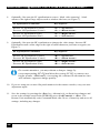
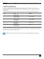
The following table illustrates which RJ45 connector pins the extenders use for various
signals. It also details the standard EIA-568B wiring scheme that is recommended for most
installations.
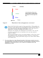
Looking into the RJ45 socket on a Remote Unit, Pin 1 is on the right and Pin 8 on the left.
Pin
Color
(EIA-568B)
Signal
1
2
White/Orange
Orange/White
Blue Video
3
6
White/Green
Green/White
Green Video
4
5
Blue/White
White/Blue
Red Video
7
8
White/Brown
Brown/White
Data
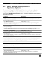
Using a crossover cable (at each end) will put the green video on the orange colored pair and
the blue video on the green colored pair.
EIA-568A wiring can also be used. Contact Technical Support for details.
49