1
6000_series_service_guide.book Page 1 Friday, March 23, 2007 2:43 PM
Agilent 6000 Series
Oscilloscopes
Service Guide
Agilent Technologies
6000_series_service_guide.book Page 2 Friday, March 23, 2007 2:43 PM
Notices
© Agilent Technologies, Inc. 2005-2007
Warranty
No part of this manual may be reproduced in
any form or by any means (including electronic storage and retrieval or translation
into a foreign language) without prior agreement and written consent from Agilent
Technologies, Inc. as governed by United
States and international copyright laws.
The material contained in this document is provided “as is,” and is subject to being changed, without notice,
in future editions. Further, to the maximum extent permitted by applicable
law, Agilent disclaims all warranties,
either express or implied, with regard
to this manual and any information
contained herein, including but not
limited to the implied warranties of
merchantability and fitness for a particular purpose. Agilent shall not be
liable for errors or for incidental or
consequential damages in connection with the furnishing, use, or performance of this document or of any
information contained herein. Should
Agilent and the user have a separate
written agreement with warranty
terms covering the material in this
document that conflict with these
terms, the warranty terms in the separate agreement shall control.
Manual Part Number
54684-97021, April 2007
54684-97001 February 2005
54684-97003 April 2005
54684-97014 November 2006
54684-97008, January 2006
54684-97010, June 2006
54684-97014, November 2006
54684-97018, March 2007
Printed in Malaysia
Agilent Technologies, Inc.
1900 Garden of the Gods Road
Colorado Springs, CO 80907 USA
defined in FAR 52.227-19(c)(1-2) (June
1987). U.S. Government users will receive
no greater than Limited Rights as defined in
FAR 52.227-14 (June 1987) or DFAR
252.227-7015 (b)(2) (November 1995), as
applicable in any technical data.
Safety Notices
CAUTION
A CAUTION notice denotes a hazard. It calls attention to an operating procedure, practice, or the like
that, if not correctly performed or
adhered to, could result in damage
to the product or loss of important
data. Do not proceed beyond a
CAUTION notice until the indicated
conditions are fully understood and
met.
Technology Licenses
A newer version of this manual
may be available at
www.agilent.com/find/mso6000
The hardware and/or software described in
this document are furnished under a license
and may be used or copied only in accordance with the terms of such license.
Restricted Rights Legend
Microsoft ® is a U.S. registered trademark
of Microsoft Corporation.
If software is for use in the performance of a
U.S. Government prime contract or subcontract, Software is delivered and licensed as
“Commercial computer software” as
defined in DFAR 252.227-7014 (June 1995),
or as a “commercial item” as defined in FAR
2.101(a) or as “Restricted computer software” as defined in FAR 52.227-19 (June
1987) or any equivalent agency regulation or
contract clause. Use, duplication or disclosure of Software is subject to Agilent Technologies’ standard commercial license
terms, and non-DOD Departments and
Agencies of the U.S. Government will
receive no greater than Restricted Rights as
WA R N I N G
A WARNING notice denotes a
hazard. It calls attention to an
operating procedure, practice, or
the like that, if not correctly performed or adhered to, could result
in personal injury or death. Do not
proceed beyond a WARNING
notice until the indicated conditions are fully understood and
met.
6000 Series Oscilloscopes Service Guide
6000_series_service_guide.book Page 3 Friday, March 23, 2007 2:43 PM
In This Service Guide
This book provides the service information for the Agilent
6000 Series Oscilloscopes. This manual is divided into these
chapters:
1
Characteristics and Specifications
This chapter lists characteristics and specifications for the
Agilent 6000 Series Oscilloscopes.
2
Testing Performance
This chapter explains how to verify correct oscilloscope
operation and perform tests to ensure that the oscilloscope
meets the performance specifications.
3
Calibrating and Adjusting
This chapter explains how to adjust the oscilloscope for
optimum operating performance.
4
Troubleshooting
This chapter begins with suggestions for solving general
problems that you may encounter with the oscilloscope.
Procedures for troubleshooting the oscilloscope follow the
problem solving suggestions.
5
Replacing 6000A Assemblies
This chapter describes how to remove assemblies from the
6000A Series oscilloscope.
6
Replacing 6000L Assemblies
This chapter describes how to remove assemblies from the
6000L Series oscilloscope.
7
Replaceable Parts
This chapter describes how to order replaceable assemblies
and parts for the Agilent 6000 Series Oscilloscopes. It
6000 Series Oscilloscopes Service Guide
3
6000_series_service_guide.book Page 4 Friday, March 23, 2007 2:43 PM
includes diagrams and parts lists for hardware that you can
order.
At the front of the book you will find safety notice
descriptions and document warranties.
Using this book with the 6000L Series oscilloscopes
The 6000L Series oscilloscopes do not have a built-in display or front panel
control keys. If you are using a 6000L Series oscilloscope, and this book refers to
using front panel controls, you can use the built-in Web control feature described
in the 6000 Series Oscilloscopes User’s Guide to complete the instructions. If you
do not have the 6000 Series Oscilloscopes User’s Guide, you may obtain a
printable electronic copy at www.agilent.com/find/mso6000.
Digital Channels
Because all of the oscilloscopes in the Agilent 6000 Series have analog channels,
the analog channel topics in this book apply to all instruments. Whenever a topic
discusses the digital channels, that information applies only to Mixed-Signal
Oscilloscope (MSO) models or DSO models that have been upgraded to an MSO.
Abbreviated instructions for pressing a series of keys
Instructions for pressing a series of keys are written in an abbreviated manner.
Instructions for pressing Key1, then pressing Key2, then pressing Key3 are
abbreviated as follows:
Press Key1 & Key2 & Key3.
The keys may be front panel keys, or softkeys, which are located directly below
the oscilloscope display.
4
6000 Series Oscilloscopes Service Guide
6000_series_service_guide.book Page 5 Friday, March 23, 2007 2:43 PM
Contents
1
Figures
9
Tables
13
Characteristics and Specifications
15
6000A Series and 6000L Series Environmental Conditions
Overvoltage Category 16
Pollution Degree 16
Pollution Degree Definitions 16
6000A Series and 6000L Series Measurement Category
Measurement Category 17
Measurement Category Definitions 17
6000A Series and 6000L Series Transient Withstand
Capability 18
6000A Series Oscilloscope Specifications
6000A Series Oscilloscope Characteristics
Testing Performance
20
30
37
Overview 38
Conventions 39
Fluke MET/CAL Procedures
List of Test Equipment
17
19
6000L Series Specifications and Characteristics
Performance characteristics 30
2
16
39
40
To construct the test connector (for use with MSO models
only) 41
6000 Series Oscilloscopes Service Guide
5
6000_series_service_guide.book Page 6 Friday, March 23, 2007 2:43 PM
Contents
To test digital channels (MSO models only)
43
To verify digital channel threshold accuracy (MSO models
only) 44
When to Test 44
What to Test 44
Verifying Test Results 44
To verify voltage measurement accuracy
To verify bandwidth
48
53
To verify horizontal Dt accuracy
58
To verify trigger sensitivity 60
Test Internal Trigger Sensitivity (all models) 62
Test External Trigger Sensitivity (2-channel models)
Test External Trigger Sensitivity (4-channel models)
64
67
Agilent 6000 Series Oscilloscopes Performance Test Record
3
Calibrating and Adjusting
70
73
User Calibration 75
To perform User Cal 75
User Cal Status 78
4
Troubleshooting
79
Solving General Problems with the Oscilloscope
80
Troubleshooting the Oscilloscope 83
Equipment required for troubleshooting 84
To check out the oscilloscope 84
To verify basic oscilloscope operation 87
To compensate the analog probes 88
Troubleshooting Flowchart 90
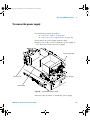
To check the 6000A Series oscilloscope power supply
To check the 6000L Series oscilloscope power supply
6
91
94
6000 Series Oscilloscopes Service Guide
6000_series_service_guide.book Page 7 Friday, March 23, 2007 2:43 PM
Contents
To check the 6000A Series or 6000L Series system board
To check the 6000A Series display 97
To check the 6000L Series display output 97
To check the fan 98
To run the internal self-tests 99
To verify default setup 99
5
Replacing 6000A Assemblies
To remove the cabinet
104
To remove the handle
105
To remove the storage lid
96
101
106
To remove the front panel assembly
To remove the keyboard assembly
To remove the display assembly
107
110
113
To remove the backlight inverter board and e-field shield
117
To remove the LCD, gasket, and protective lens from the display
mount 122
To remove the power supply shield
To remove the power supply
To remove the power shaft
To remove the AC input board
125
129
130
131
To remove the batteries (Option BAT only)
133
To remove the battery controller board (Option BAT only)
To remove the fan
137
To remove the system board
6
Replacing 6000L Assemblies
To remove the bottom cover
6000 Series Oscilloscopes Service Guide
135
139
143
145
7
6000_series_service_guide.book Page 8 Friday, March 23, 2007 2:43 PM
Contents
To remove the front panel assembly
To remove the system board
148
To remove the power supply
150
To remove the fan
146
152
To remove the AC power input assembly
To remove the power shaft
7
Replaceable Parts
154
156
157
Ordering Replaceable Parts 158
Listed Parts 158
Unlisted Parts 158
Direct Mail Order System 158
Exchange Assemblies 159
Power Cords
160
Replaceable Parts for 6000A Series Oscilloscopes 162
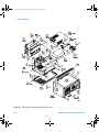
6000A Series Oscilloscope Exploded Views 162
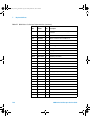
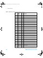
6000A Series Oscilloscope Replaceable Parts List 165
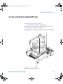
Replaceable Parts for 6000A Series Option BAT
Oscilloscopes 170
6000A Series Option BAT Oscilloscope Exploded View 170
6000A Series Option BAT Oscilloscope Replaceable Parts
List 172
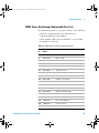
Replaceable Parts for 6000L Series Oscilloscopes 173
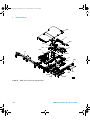
6000L Series Oscilloscope Exploded Views 173
6000L Series Oscilloscope Replaceable Parts List 175
Index
8
177
6000 Series Oscilloscopes Service Guide
6000_series_service_guide.book Page 9 Friday, March 23, 2007 2:43 PM
Figures
Figure 1. Constructing the 8-by-2 Connector 42
Figure 2. Setting Up Equipment and Test Connector for the
Threshold Test 46
Figure 3. Connect equipment for voltage measurement accuracy
test 51
Figure 4. Using a Blocking Capacitor to Reduce Noise 52
Figure 5. Connect equipment for bandwidth test 55
Figure 6. Connect equipment for internal trigger sensitivity
test 62
Figure 7. Connect equipment for external trigger sensitivity test
(2-channel models) 65
Figure 8. Connect equipment for external trigger sensitivity test
(4-channel models) 68
Figure 9. User Calibration cable for 2-channel oscilloscope 76
Figure 10. User Calibration cable for 4-channel oscilloscope 77
Figure 11. 6000A Series start up sequence 85
Figure 12. 6000L Series LED indicators 86
Figure 13. Example pulses 88
Figure 14. System Board Test Points 92
Figure 15. Location of the Fan Connector (shown on 6000A
model) 98
Figure 16. Default setup screen 100
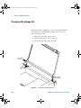
Figure 17. Removing the cabinet 104
Figure 18. Removing handle 105
Figure 19. Installing the hinged storage lid 106
Figure 20. Removing the intensity knob and T6 screws 107
Figure 21. Disconnecting ribbon cable and releasing tab
retainers 108
Figure 22. Removing the front panel 108
Figure 23. Removing the keyboard assembly 111
6000 Series Oscilloscopes Service Guide
9
6000_series_service_guide.book Page 10 Friday, March 23, 2007 2:43 PM
Figures
Figure 24. Removing the main shield and disconnecting the display
cables 114
Figure 25. Removing the display assembly 115
Figure 26. Installing the display 116
Figure 27. Opening the backlight inverter shield 117
Figure 28. Removing the backlight inverter 119
Figure 29. Removing the backlight inverter shield 120
Figure 30. Closing the shield 121
Figure 31. Release display mount latches 122
Figure 32. Removing the LCD, gasket, and protective lens 123
Figure 33. Latch over face of sheet metal housing 124
Figure 34. Release hook legs from deck. 125
Figure 35. Dielectric insulator tape. 126
Figure 36. Proper angles for tabs and hook legs. 127
Figure 37. Tilt to insert tabs. 127
Figure 38. Insert hook legs and lock in place. 128
Figure 39. Removing the power supply 129
Figure 40. Removing the power shaft latch 130
Figure 41. Removing the AC input board 131
Figure 42. Removing the batteries 133
Figure 43. Removing the battery controller board 136
Figure 44. Removing main shield and disconnecting fan
cable. 137
Figure 45. Removing the fan 138
Figure 46. Preparing to remove the system board 140
Figure 47. Removing the system board 141
Figure 48. Removing the cover 145
Figure 49. Removing the intensity knob 146
Figure 50. Disconnecting ribbon cable and releasing tab
retainers 147
Figure 51. Preparing to remove the system board 149
Figure 52. Avoid damage to thermal pads (500 MHZ models
only) 149
10
6000 Series Oscilloscopes Service Guide
6000_series_service_guide.book Page 11 Friday, March 23, 2007 2:43 PM
Figures
Figure 53.
Figure 54.
Figure 55.
Figure 56.
Figure 57.
Figure 58.
Figure 59.
Figure 60.
Removing the power supply. 150
Removing the fan. 152
Installing the fan. 153
Removing the AC power input board. 155
Removing the power shaft. 156
6000A Series Oscilloscope Exploded View 1 of 2
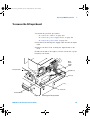
6000A Series Oscilloscope Exploded View 2 of 2
6000A Series Option BAT Oscilloscope Exploded
View 171
Figure 61. 6000L Series Oscilloscope Exploded View 174
6000 Series Oscilloscopes Service Guide
163
164
11
6000_series_service_guide.book Page 12 Friday, March 23, 2007 2:43 PM
Figures
12
6000 Series Oscilloscopes Service Guide
6000_series_service_guide.book Page 13 Friday, March 23, 2007 2:43 PM
Tables
Table 1.
Table 2.
Table 3.
Table 4.
Table 5.
Table 6.
Table 7.
Table 8.
Table 9.
Table 10.
Table 11.
Table 12.
Table 13.
Table 14.
Table 15.
Table 16.
Table 17.
Table 18.
Table 19.
6000 Series Oscilloscopes Service Guide
Warranted specifications 19
Characteristics 20
Conventions 39
List of test equipment 40
Materials required to construct the test
connectors 41
Equipment Required to Test Digital Channel Threshold
Accuracy 45
Threshold Accuracy Voltage Test Settings 47
Equipment Required to Verify Voltage Measurement
Accuracy 49
Settings Used to Verify Voltage Measurement
Accuracy 50
Equipment Required to Verify Bandwidth 54
Equipment Required to Verify Horizontal Dt
Accuracy 59
Equipment Required to Verify Trigger Sensitivity 61
Equipment Required to Troubleshoot the
Oscilloscope 84
System Board Test Points 96
Display Signals on the System Board 97
Power Cords 160
6000A Series Oscilloscope Replaceable Parts 165
6000A Series Option BAT Replaceable Parts 172
6000L Series Oscilloscope Replaceable Parts 175
13
6000_series_service_guide.book Page 14 Friday, March 23, 2007 2:43 PM
Tables
14
6000 Series Oscilloscopes Service Guide
6000_series_service_guide.book Page 15 Friday, March 23, 2007 2:43 PM
Agilent 6000 Series Oscilloscope
User’s Guide
1
Characteristics and Specifications
6000A Series and 6000L Series Environmental Conditions 16
6000A Series and 6000L Series Measurement Category 17
6000A Series Oscilloscope Specifications 19
6000A Series Oscilloscope Characteristics 20
6000L Series Specifications and Characteristics 30
This chapter lists characteristics and specifications for the
Agilent 6000 Series Oscilloscopes.
Agilent Technologies
15
6000_series_service_guide.book Page 16 Friday, March 23, 2007 2:43 PM
1
Characteristics and Specifications
6000A Series and 6000L Series Environmental Conditions
Overvoltage Category
This product is intended to be powered by MAINS that
comply to Overvoltage Category II, which is typical of
cord- and- plug connected equipment.
Pollution Degree
The 6000 Series Oscilloscope may be operated in
environments of Pollution Degree 2 (or Pollution Degree 1).
Pollution Degree Definitions
Pollution Degree 1: No pollution or only dry, non- conductive
pollution occurs. The pollution has no influence. Example: A
clean room or climate controlled office environment.
Pollution Degree 2. Normally only dry non- conductive
pollution occurs. Occasionally a temporary conductivity
caused by condensation may occur. Example: General indoor
environment.
Pollution Degree 3: Conductive pollution occurs, or dry,
non- conductive pollution occurs which becomes conductive
due to condensation which is expected. Example: Sheltered
outdoor environment.
16
6000 Series Oscilloscopes Service Guide
6000_series_service_guide.book Page 17 Friday, March 23, 2007 2:43 PM
Characteristics and Specifications
1
6000A Series and 6000L Series Measurement Category
Measurement Category
The 6000 Series oscilloscope is intended to be used for
measurements in Measurement Category I.
Measurement Category Definitions
Measurement category I is for measurements performed on
circuits not directly connected to MAINS. Examples are
measurements on circuits not derived from MAINS, and
specially protected (internal) MAINS derived circuits. In the
latter case, transient stresses are variable; for that reason,
the transient withstand capability of the equipment is made
known to the user.
Measurement category II is for measurements performed on
circuits directly connected to the low voltage installation.
Examples are measurements on household appliances,
portable tools and similar equipment.
Measurement category III is for measurements performed in
the building installation. Examples are measurements on
distribution boards, circuit- breakers, wiring, including cables,
bus- bars, junction boxes, switches, socket- outlets in the fixed
installation, and equipment for industrial use and some
other equipment, for example, stationary motors with
permanent connection to the fixed installation.
Measurement category IV is for measurements performed at
the source of the low- voltage installation. Examples are
electricity meters and measurements on primary overcurrent
protection devices and ripple control units.
6000 Series Oscilloscopes Service Guide
17
6000_series_service_guide.book Page 18 Friday, March 23, 2007 2:43 PM
1
Characteristics and Specifications
6000A Series and 6000L Series Transient Withstand Capability
CAUTION
Maximum input voltage for analog inputs:
CAT I 300 Vrms, 400 Vpk; transient overvoltage 1.6 kVpk
CAT II 100 Vrms, 400 Vpk
with 10073C or 10074C 10:1 probe: CAT I 500 Vpk, CAT II 400 Vpk
CAUTION
CAUTION
CAUTION
Do not exceed 5 Vrms in 50 Ω mode on the 2-channel models. Input
protection is enabled in 50 Ω mode, and the 50 Ω load will disconnect
if greater than 5 Vrms is detected. However, the input could still be
damaged, depending on the time constant of the signal.
The 50 Ω input protection mode only functions when the oscilloscope
is powered on.
Maximum input voltage for logic channels:
±40 V peak CAT I; transient overvoltage 800 Vpk
18
6000 Series Oscilloscopes Service Guide
6000_series_service_guide.book Page 19 Friday, March 23, 2007 2:43 PM
Characteristics and Specifications
1
6000A Series Oscilloscope Specifications
All specification are warranted. Specifications are valid after
a 30- minute warm- up period and within ±10°C of last “User
Cal” temperature.
Table 1
Warranted specifications
Vertical system: oscilloscope channels
Bandwidth (–3dB)
MSO/DSO601xA: DC to 100 MHz
MSO/DSO603xA: DC to 300 MHz
MSO/DSO605xA: DC to 500 MHz
MSO/DSO610xA: DC to 1 GHz
DC vertical gain accuracy
±2.0% full scale
±{DC vertical gain accuracy + 0.4% full scale (~1 LSB)}
Dual cursor accuracy1
Example: for 50 mV signal, oscilloscope set to 10 mV/div (80 mV full scale), 5 mV offset,
accuracy = ±{2.0% (80 mV) + 0.4% (80 mV)} = ±1.92 mV
Vertical system: logic channels (MSO6000A or MSO-upgraded DSO6000A only)
Threshold accuracy
±(100 mV + 3% of threshold setting)
Scope channel triggering
Sensitivity
<10 mV/div: greater of 1 div or 5mV; ≥10 mV/div: 0.6 div
Logic (D15 - D0) channel triggering (MSO6000A or MSO-upgraded DSO6000A only)
Threshold accuracy
±(100 mV + 3% of threshold setting)
1
1 mV/div is a magnification of 2 mV/div setting for 100 MHz models and 2 mV/div is a magnification of 4 mV/div setting for 300 MHz - 1 GHz models. For
vertical accuracy calculations, use full scale of 16 mV for 1 mV/div sensitivity setting and 32 mV for 2 mV/div sensitivity setting.
6000 Series Oscilloscopes Service Guide
19
6000_series_service_guide.book Page 20 Friday, March 23, 2007 2:43 PM
1
Characteristics and Specifications
6000A Series Oscilloscope Characteristics
All characteristics are the typical performance values and
are not warranted. Characteristics are valid after a
30- minute warm- up period and within ±10°C of last “User
Cal” temperature.
Table 2
Characteristics
Acquisition: oscilloscope channels
Sample rate
MSO/DSO601xA/603xA: 2 GSa/sec each channel
MSO/DSO605xA/610xA: 4 GSa/sec half channel*, 2 GSa/sec each channel
Standard memory depth
With logic channels turned off,
1 Mpts half channel*, 500 kpts each channel
With logic channels turned on,
625 kpts half channel*, 312 kpts each channel
Optional memory depth
With logic channels turned off,
Option 2ML or 2MH – 2 Mpts half channel*, 1 Mpts each channel
Option 8ML or 8MH – 8 Mpts half channel*, 4 Mpts each channel
With logic channels turned on,
Option 2ML or 2MH – 1.25 Mpts half channel*, 625 kpts each channel
Option 8ML or 8MH – 5 Mpts half channel*, 2.5 Mpts each channel
Vertical resolution
8 bits
Peak detection
MSO/DSO601xA: 1-ns peak detect
MSO/DSO603xA: 500-ps peak detect
MSO/DSO605xA/610xA: 250-ps peak detect
Averaging
Selectable from 2, 4, 8, 16, 32, 64 … to 65536
High resolution mode
Average mode with #avg = 1
12 bits of resolution when ≥10 µs/div, at 4 GSa/s or ≥20 µs/div, at 2 GSa/s
Filter
Sinx/x interpolation (single shot BW = sample rate/4 or bandwidth of oscilloscope,
whichever is less) with vectors on and in real-time mode
* Half channel is when only one of channel pair 1 or 2 is turned on, or only channel pair 3 or 4 is turned on.
20
6000 Series Oscilloscopes Service Guide
6000_series_service_guide.book Page 21 Friday, March 23, 2007 2:43 PM
Characteristics and Specifications
1
Acquisition: logic channels (MSO6000A or MSO-upgraded DSO6000A only)
Sample rate
2 GSa/sec one pod, 1 GSa/sec each pod
Maximum input frequency
250 MHz
Standard memory depth
With oscilloscope channels turned off,
1 Mpts one pod, 500 kpts each pod
With oscilloscope channels turned on,
312 kpts one pod, 156 kpts each pod
Optional memory depth
With oscilloscope channels turned off,
Option 2ML or 2MH – 2 Mpts one pod, 1 Mpts each pod
Option 8ML or 8MH – 8 Mpts one pod, 4 Mpts each pod
With oscilloscope channels turned on,
Option 2ML or 2MH – 625 kpts one pod, 312 kpts each pod
Option 8ML or 8MH – 2.5 Mpts one pod, 1.25 Mpts each pod
Vertical resolution
1 bit
Glitch detection
2 ns (min pulse width)
Vertical system: oscilloscope channels
Scope channels
MSO/DSO6xx2A: Ch 1 and 2 simultaneous acquisition
MSO/DSO6xx4A: Ch 1, 2, 3 and 4 simultaneous acquisition
AC coupled
MSO/DSO601xA: 3.5 Hz to 100 MHz
MSO/DSO603xA: 3.5 Hz to 300 MHz
MSO/DSO605xA: 3.5 Hz to 500 MHz
MSO/DSO610xA: 3.5 Hz to 1 GHz
Calculated rise time
MSO/DSO601xA: 3.5 nsec
(= 0.35/bandwidth)
MSO/DSO603xA: 1.17 nsec
MSO/DSO605xA: 700 psec
MSO/DSO610xA: 350 psec
Single-shot bandwidth
MSO/DSO601xA: 100 MHz
MSO/DSO603xA: 300 MHz
MSO/DSO605xA: 500 MHz
MSO/DSO610xA: 1 GHz (in half-channel mode, i.e., one channel of channel pair is on)
MSO/DSO601xA: 1 mV/div to 5 V/div (1 MΩ)
Range1
MSO/DSO603xA and MSO/DSO605xA: 2 mV/div to 5 V/div (1 MΩ or 50 Ω)
MSO/DSO610xA: 2 mV/div to 5 V/div (1 MΩ), 2 mV/div to 1 V/div (50 Ω)
Maximum input
CAT I 300 Vrms, 400 Vpk; transient overvoltage 1.6 kVpk
CAT II 100 Vrms, 400 Vpk
With 10073C 10:1 probe: CAT I 500 Vpk, CAT II 400 Vpk
Offset range
±5 V on ranges <10 mV/div; ±20 V on ranges 10 mV/div to 200 mV/div; ±75 V on ranges
>200 mV/div
1 1 mV/div is a magnification of 2 mV/div setting for 100 MHz models and 2 mV/div is a magnification of 4 mV/div setting for 300 MHz - 1 GHz models. For
vertical accuracy calculations, use full scale of 16 mV for 1 mV/div sensitivity setting and 32 mV for 2 mV/div sensitivity setting.
6000 Series Oscilloscopes Service Guide
21
6000_series_service_guide.book Page 22 Friday, March 23, 2007 2:43 PM
1
Characteristics and Specifications
Vertical system: oscilloscope channels (continued)
Dynamic range
±8 div
Input impedance
MSO/DSO601xA: 1 MΩ ± 1% || 11 pF
MSO/DSO603xA/605xA/610xA: 1 MΩ ± 1% || 14 pF or 50 Ω ± 1.5%, selectable
Coupling
AC, DC
BW limit
25 MHz selectable, on the 300 MHz, 500 MHz, and 1 GHz bandwidth models
20 MHz selectable, on the 100 MHz bandwidth models
Channel-to-channel isolation
DC to max bandwidth >40 dB
Standard probes
MSO/DSO601xA: 10:1 10074C shipped standard for each oscilloscope channel
MSO/DSO603xA/605xA/610xA: 10:1 10073C shipped standard for each oscilloscope
channel
Probe ID
MSO/DSO601xA: Auto probe sense
MSO/DSO603xA/605xA/610xA: Auto probe sense and AutoProbe interface
Agilent- and Tektronix-compatible passive probe sense
ESD tolerance
±2 kV
Noise peak-to-peak
MSO/DSO601xA: 3% full scale or 2 mV, whichever is greater
MSO/DSO603xA: 3% full scale or 3 mV, whichever is greater
MSO/DSO605xA: 3% full scale or 3.6 mV, whichever is greater
MSO/DSO610xA: 3% full scale or 4 mV, whichever is greater
DC vertical offset accuracy
≤ 200 mV/div: ±0.1 div ±2.0 mV ±0.5% offset value;
>200 mV/div: ±0.1 div ±2.0 mV ±1.5% offset value
±{DC vertical gain accuracy + DC vertical offset accuracy + 0.2% full scale (~1/2 LSB)}
Single cursor accuracy1
Example: for 50 mV signal, oscilloscope set to 10 mV/div (80 mV full scale), 5 mV offset,
accuracy = ±{2.0% (80 mV) + 0.1 (10 mV) + 2.0 mV + 0.5% (5 mV) + 0.2%(80 mV)} =
± 4.785 mV
Vertical system: logic channels (MSO6000A or MSO-upgraded DSO6000A only)
Number of channels
16 logic timing channels – labeled D15 - D0
Threshold groupings
Pod 1: D7 - D0
Pod 2: D15 - D8
Threshold selections
TTL, CMOS, ECL and user-definable (selectable by pod)
User-defined threshold range
±8.0 V in 10 mV increments
Maximum input voltage
±40 V peak CAT I; transient overvoltage 800 Vpk
Input dynamic range
±10 V about threshold
Minimum input voltage swing
500 mV peak-to-peak
Input capacitance
~8 pF
Input resistance
100 kΩ ±2% at probe tip
Channel-to-channel skew
2 ns typical, 3 ns maximum
1 1 mV/div is a magnification of 2 mV/div setting for 100 MHz models and 2 mV/div is a magnification of 4 mV/div setting for 300 MHz - 1 GHz models. For
vertical accuracy calculations, use full scale of 16 mV for 1 mV/div sensitivity setting and 32 mV for 2 mV/div sensitivity setting.
22
6000 Series Oscilloscopes Service Guide
6000_series_service_guide.book Page 23 Friday, March 23, 2007 2:43 PM
Characteristics and Specifications
Horizontal
Range
Resolution
Timebase accuracy
Vernier
Delay range
Analog delta-t accuracy
Logic delta-t accuracy
Modes
XY
Reference positions
Trigger system
Sources
Modes
Holdoff time
Trigger jitter
1
MSO/DSO601xA: 5 nsec/div to 50 sec/div
MSO/DSO603xA: 2 nsec/div to 50 sec/div
MSO/DSO605xA: 1 nsec/div to 50 sec/div
MSO/DSO610xA: 500 psec/div to 50 sec/div
2.5 psec
15 ppm (±0.0015%)
1-2-5 increments when off, ~25 minor increments between major settings when on
Pre-trigger (negative delay):
Greater of 1 screen width or 1 ms (with 8 Mpts memory option)
Greater of 1 screen width or 250 µs (with 2 Mpts memory option)
Greater of 1 screen width or 125 µs (with standard memory)
Post-trigger (positive delay): 1 s - 500 seconds
Same channel: ±0.0015% reading ±0.1% screen width ±20 ps
Channel-to-channel: ±0.0015% reading ±0.1% screen width ±40 ps
Same channel example (MSO/DSO605xA):
For signal with pulse width of 10 µs, oscilloscope set to 5 µs/div (50 µs screen width),
delta-t accuracy = ±{0.0015% (10 µs) + 0.1% (50 µs) + 20 ps} = 50.17 ns
Same channel: ±0.005% reading ±0.1% screen width ±(1 logic sample period, 1 ns)
Channel-to-channel: ±0.005% reading ±0.1% screen width ±(1 logic sample period)
±chan-to-chan skew
Same channel example:
For signal with pulse width of 10 µs, oscilloscope set to 5 µs/div (50 µs screen width),
delta-t accuracy = ±{0.005% (10 µs) + 0.1% (50 µs) + 1 ns} = 51.5 ns
Main, delayed, roll, XY
Bandwidth: Max bandwidth
Phase error @ 1 MHz: <0.5 degrees
Z Blanking: 1.4 V blanks trace (use external trigger on MSO/DSO6xx2A,
channel 4 on MSO/DSO6xx4A)
Left, center, right
MSO6xx2A: Ch 1, 2, line, ext, D15 - D0
DSO6xx2A h 1, 2, line, ext
MSO6xx4A: Ch 1, 2, 3, 4, line, ext, D15 - D0
DSO6xx4A: Ch 1, 2, 3, 4, line, ext
Auto, Normal (triggered), single
~60 ns to 10 seconds
15 ps rms
6000 Series Oscilloscopes Service Guide
23
6000_series_service_guide.book Page 24 Friday, March 23, 2007 2:43 PM
1
Characteristics and Specifications
Trigger system (continued)
Selections
Edge
Pattern
Pulse width
TV
Sequence
CAN
LIN
USB
I 2C
SPI
24
Edge, pulse width, pattern, TV, duration, sequence, CAN, LIN, USB, I2C, SPI, Nth edge
burst.
Trigger on a rising, falling, alternating or either edge of any source
Trigger at the beginning of a pattern of high, low, and don't care levels and/or a rising or
falling edge established across any of the analog and digital channels, but only after a
pattern has been established for a minimum of 2 nsec.
The oscilloscope channel's high or low level is defined by that channel's trigger level.
The logic channel’s trigger level is defined by the threshold for the pod, 0 - 7 or 8 - 15.
Trigger when a positive- or negative-going pulse is less than, greater than, or within a
specified range on any of the source channels.
Minimum pulse width setting:
5 ns (MSO/DSO601xA/603xA oscilloscope channels)
2 ns (MSO/DSO605xA/610xA oscilloscope channels)
2 ns (logic channels on MSO6000A or
MSO-upgraded DSO6000A)
Maximum pulse width setting: 10 s
Trigger using any oscilloscope channel on most analog progressive and interlaced video
standards including HDTV/EDTV, NTSC, PAL, PAL-M or SECAM broadcast standards.
Select either positive or negative sync pulse polarity. Modes supported include Field 1,
Field 2, all fields, all lines, or any line within a field. TV trigger sensitivity: 0.5 division of
sync signal. Trigger holdoff time can be adjusted in half field increments.
Arm on event A, trigger on event B, with option to reset on event C or time delay.
Trigger on CAN (Controller Area Network) version 2.0A and 2.0B signals. Trigger on the
start of frame (SOF) bit (standard). N5424A option supports triggering on remote frame
ID (RTR), data frame ID (~RTR), remote or data frame ID, data frame ID and data, error
frame, all errors, acknowledge error and overload frame.
Trigger on LIN (Local Interconnect Network) sync break at beginning of message frame
(standard). N5424A option supports triggering on frame ID.
Trigger on USB (Universal Serial Bus) start of packet, end of packet, reset complete,
enter suspend, or exit suspend on the differential USB data lines. USB low speed and full
speed are supported.
Trigger on I2C (Inter-IC bus) serial protocol at a start/stop condition or user defined
frame with address and/or data values. Also trigger on missing acknowledge, restart,
EEPROM read, and 10-bit write.
Trigger on SPI (Serial Protocol Interface) data pattern during a specific framing period.
Supports positive and negative Chip Select framing as well as clock Idle framing and
user-specified number of bits per frame.
6000 Series Oscilloscopes Service Guide
6000_series_service_guide.book Page 25 Friday, March 23, 2007 2:43 PM
Characteristics and Specifications
1
Duration
Trigger on a multi-channel pattern whose time duration is less than a value, greater than
a value, greater than a time value with a timeout, or inside or outside of a set of time
values.
Minimum duration setting: 2 ns
Maximum duration setting: 10 s
Nth Edge Burst Trigger on the Nth edge of a burst that occurs after an idle time.
Trigger system (continued)
AutoScale
Oscilloscope channel triggering
Range (internal)
Coupling
Finds and displays all active oscilloscope and logic (for MSO6000A series MSO)
channels, sets edge trigger mode on highest-numbered channel, sets vertical sensitivity
on oscilloscope channels and thresholds on logic channels, time base to display ~1.8
periods. Requires minimum voltage >10 mVpp, 0.5% duty cycle and minimum frequency
>50 Hz.
±6 div from center screen
AC (~3.5 Hz on MSO/DSO601xA, ~10 Hz on MSO/DSO603xA/605xA/610xA),
DC, noise reject, HF reject and LF reject (~50 kHz)
Logic (D15 - D0) channel triggering (MSO6000A or MSO-upgraded DSO6000A only)
Threshold range (user defined)
±8.0 V in 10 mV increments
Predefined thresholds
TTL = 1.4 V, CMOS = 2.5 V, ECL = -1.3 V
External (EXT) triggering
Input impedance
Maximum input
Range
MSO/DSO6xx2A
(2-/2+16-ch models)
MSO/DSO6012A: 1 MΩ ±3% || 11 pF or 50 Ω
MSO/DSO6032A/6052A/6102A: 1 MΩ ±3% || 14 pF or
50 Ω
CAT I 300 Vrms, 400 Vpk, CAT II 100 Vrms, 400 Vpk
With 10073C 10:1 probe: CAT I 500 Vpk, CAT II 400 Vpk
5 Vrms with 50-ohm input
DC coupling: trigger level ± 1V and ± 8V
6000 Series Oscilloscopes Service Guide
MSO/DSO6xx4A
(4-/4+16-ch models)
MSO/DSO6014A:
1.015 kΩ ±5%
MSO/DSO6034A/6054A/
6104A: 2.14 kΩ ±5%
±15 V
±5 V
25
6000_series_service_guide.book Page 26 Friday, March 23, 2007 2:43 PM
1
Characteristics and Specifications
Sensitivity
Coupling
Probe ID
Display system
Display
Throughput of oscilloscope
channels
Resolution
Controls
Built-in help system
Real-time clock
Measurement features
Automatic measurements
Voltage (scope channels only)
Time
Counter
Threshold definition
26
For ± 1V range setting:
DC to 100 MHz, 100 mV;
MSO/DSO6032A/6052A/6102A
>100 MHz to bandwidth of oscilloscope: 200 mV
For ± 8V range setting:
DC to 100 MHz, 250 mV;
MSO/DSO6032A/6052A/6102A
>100 MHz to bandwidth of oscilloscope: 500 mV
AC (~3.5 Hz), DC, noise reject, HF reject and
LF reject (~50 kHz)
MSO/DSO601xA: Auto probe sense
MSO/DSO603xA/605xA/610xA: Auto probe sense and
AutoProbe interface
Agilent- and Tektronix-compatible passive probe sense
MSO/DSO6014A:
DC to 100 MHz: 500 mV
MSO/DSO6034A/6054A/
6104A:
DC to 500 MHz: 500 mV
6.3-inch (161 mm) diagonal color TFT LCD
Up to 100,000 waveforms/sec in real-time mode
XGA –
768 vertical by 1024 horizontal points (screen area);
640 vertical by 1000 horizontal points (waveform area)
256 levels of intensity scale
Waveform intensity on front panel. Vectors on/off; infinite persistence on/off,
8 x 10 grid with intensity control
Key-specific help (in English) displayed by pressing and holding key or softkey of interest
Time and date (user adjustable)
Measurements are continuously updated. Cursors track last selected measurement.
Peak-to-peak, maximum, minimum, average, amplitude, top, base, overshoot, preshoot,
RMS, standard deviation
Frequency, period, + width, – width and duty cycle on any channel.
Rise time, fall time, X at max Y (time at max volts), X at min Y (time at min volts), delay,
and phase on oscilloscope channels only.
Built-in 5-digit frequency counter on any channel. Counts up to the oscilloscope’s
bandwidth (1 GHz max). The counter resolution can be increased to 8 digits with an
external 10 MHz reference.
Variable by percent and absolute value; 10%, 50%, 90% default for time measurements
6000 Series Oscilloscopes Service Guide
6000_series_service_guide.book Page 27 Friday, March 23, 2007 2:43 PM
Characteristics and Specifications
Cursors
Waveform math
FFT
Points
Source of FFT
Window
Noise floor
Amplitude
Frequency resolution
Maximum frequency
Storage
Save/recall
Storage type and format
I/O
Standard ports
Max transfer rate
Printer compatibility
General characteristics
Physical size
Weight
Probe comp output
1
Manually or automatically placed readout of Horizontal (X, DX, 1/DX) and Vertical
(Y, DY). Additionally logic or oscilloscope channels can be displayed as binary or hex
values.
One function of 1-2, 1x2, FFT, differentiate, integrate.
Source of FFT, differentiate, integrate: oscilloscope channels 1 or 2, 1-2, 1+2, 1x2.
Fixed at 1000 points
Scope channels 1 or 2 (or 3 or 4 on MSO/DSO6xx4A only), 1+2, 1-2, 1*2
Rectangular, flattop, hanning
–50 to –90 dB depending on averaging
Display in dBV, dBm at 50 Ω
0.05/time per div
50/time per div
10 setups and traces can be saved and recalled using internal non-volatile memory
USB 1.1 host ports on front and rear panels
Image formats: BMP (8-bit), BMP (24-bit), PNG (24-bit)
Data formats: X and Y (time/voltage) values in CSV format, ASCII XY format, BIN format
Trace/setup formats: Recalled
USB 2.0 high speed device, two USB 1.1 host ports, 10/100-BaseT LAN, IEEE488.2 GPIB,
XGA video output
IEEE488.2 GPIB: 500 kbytes/sec
USB (USBTMC-USB488): 3.5 Mbytes/sec
100 Mbps LAN (TCP/IP): 1 Mbytes/sec
Selected HP Deskjet and Officejet printers
35.4 cm wide x 18.8 cm high x 28.2 cm deep (without handle)
39.9 cm wide x 18.8 cm high x 28.2 cm deep (with handle)
Net: 4.9 kgs (10.8 lbs)
Shipping: 9.4 kgs (20.7 lbs)
Frequency ~1.2 kHz, Amplitude ~2.5 V
6000 Series Oscilloscopes Service Guide
27
6000_series_service_guide.book Page 28 Friday, March 23, 2007 2:43 PM
1
Characteristics and Specifications
Trigger out
10 MHz ref in/out
Kensington lock
When “Triggers” is selected (delay ~17 ns; 23 ns for 100 MHz bandwidth models)
0 to 5 V into open circuit
0 to 2.5 V into 50 Ω
When “Source Frequency” or “Source Frequency/8” is selected
0 to 580 mV into open circuit
0 to 290 mV into 50 Ω
Max frequency output:
350 MHz (in Source Frequency mode when terminated in 50 Ω)
125 MHz (in Source Frequency/8 mode when terminated in 50 Ω)
TTL out, 180 mV to 1 V amplitude with 0 to 2 V offset
Connection on rear panel for security
Power requirements
Line Rating
~Line 120 W max, 96-144 V/48-440 Hz, 192-288 V/48-66 Hz, automatic selection
Environmental characteristics
Ambient temperature
Humidity
Altitude
Vibration
Shock
Pollution degree2
Indoor use
Other
Measurement categories
Regulatory information
Supplementary information
Operating –10 °C to +55 °C; non-operating –51 °C to +71 °C
Operating 95% RH at 40 °C for 24 hr; non-operating 90% RH at 65 °C for 24 hr
Operating to 4,570 m (15,000 ft); non-operating to 15,244 m (50,000 ft)
Agilent class B1 and MIL-PRF-28800F; Class 3 random
Agilent class B1 and MIL-PRF-28800F; (operating 30 g, 1/2 sine, 11-ms duration,
3 shocks/axis along major axis. Total of 18 shocks)
Normally only dry non-conductive pollution occurs.
Occasionally a temporary conductivity caused by condensation must be expected.
Rated for indoor use only
CAT I: Mains isolated
CAT II: Line voltage in appliance and to wall outlet
Safety IEC 61010-1:2001 / EN 61010-1:2001
Canada: CSA C22.2 No. 61010-1:2004
USA: UL 61010-1:2004
The product herewith complies with the requirements of the Low Voltage Directive
73/23/EEC and the EMC Directive 89/336/EEC, and carries the CE-marking accordingly.
The product was tested in a typical configuration with HP/Agilent test systems.
Product specifications, characteristics, and descriptions in this document are subject to
change without notice.
28
6000 Series Oscilloscopes Service Guide
6000_series_service_guide.book Page 29 Friday, March 23, 2007 2:43 PM
Characteristics and Specifications
WA R N I N G
1
Use this instrument only for measurements within its specified
measurement categories.
6000 Series Oscilloscopes Service Guide
29
6000_series_service_guide.book Page 30 Friday, March 23, 2007 2:43 PM
1
Characteristics and Specifications
6000L Series Specifications and Characteristics
Performance characteristics
Scope input
Channels
Bandwidth (-3 dB)*
Maximum input
Full Scale range1
Input impedance
Offset range
Connector
BW limit
Noise peak-to-peak
Ch 1, 2, 3 and 4 simultaneous acquisition
DSO6014L: DC to 100 MHz
DSO6054L: DC to 500 MHz
DSO6104L: DC to 1 GHz
CAT I 300 Vrms, 400 Vpk, CAT II 100 Vrms, 400
Vpk
With 10073C/10074C 10:1 probe: CAT I 500 Vpk,
CAT II 400 Vpk
5 Vrms with 50 Ω input
DSO6014L: 1 mV/div to 5 V/div (1 MΩ)
DSO6054L: 2 mV/div to 5 V/div (1 ΜΩ or 50 Ω)
DSO6104L: 2 mV/div to 5 V/div (1 MΩ), 2 mV/div
to 1 V/div (50 Ω)
DSO6014L2: 1 MΩ ± 1% || 11pF
DSO6054L/6104L: 1 MΩ ± 1% || 14pF or 50 MΩ
± 1.5%, selectable
Coupling AC, DC
±5 V on ranges < 10 mV/div
±20 V on ranges 10 mV/div to 200 mV/div
±75 V on ranges ≥ 200 mV/div
BNC
DSO6014L: 20MHz
DSO6054L/6104L: 25 MHz selectable
DSO6014L: 3% full scale or 2 mV, whichever is
greater
DSO6054L: 3% full scale or 3.6 mV, whichever is
greater
DSO6104L: 3% full scale or 4.5 mV, whichever is
greater
* Denotes warranted specifications, all others are typical. Specifications are valid
after a 30-minute warm-up period and ±10 °C from firmware calibration
temperature.
1 1 mV/div is a magnification of 2 mV/div. 2 mV/div is a magnification of 4 mV/div
setting. For vertical accuracy calculations, use full scale of 16 mV for 1 mV/div
sensitivity setting and 32 mV for 2 mV/div sensitivity setting.
2 Four 50 Ω termination adapters are supplied with DSO6014L.
30
6000 Series Oscilloscopes Service Guide
6000_series_service_guide.book Page 31 Friday, March 23, 2007 2:43 PM
Characteristics and Specifications
1
Logic channels (with MSO option)
Number of channels
Maximum input frequency
Sample rate
Standard memory depth
Vertical resolution
Threshold selections
Maximum input voltage
Glitch detection
16 logic timing channels - labeled D15 - D0
250 MHz
2 GSa/sec one pod, 1 GSa/sec each pod
2.5 Mpts one pod, 1.25 Mpts each pod
1 bit
TTL, CMOS, ECL, user-definable (selectable by
pod)
±40 V peak CAT I
2 ns (min pulse width)
Analog to digital conversion
Vertical resolution
Sample rate
8 bits
DSO6014L: 2 GSa/sec
DSO6054L/6104L: 4 GSa/sec half channel,
2 GSa/sec each channel
Equivalent-time sample rate: 400 GSa/s (when
realtime mode is turned off)
Standard memory depth
Time range
8 Mpts per half channel, 4 Mpts per each channel
5 nsec/div to 50 sec/div (DSO6014L)
1 nsec/div to 50 sec/div (DSO6054L)
500 psec/div to 50 sec/div (DSO6104L)
Acquisition
Acquisition mode
Peak detection
Averaging
High resolution mode
Filter
6000 Series Oscilloscopes Service Guide
Normal, Peak Detect, Averaging, High Resolution
DSO6014L: 1 nsec peak detect
DSO6054L/6104L: 250 psec peak detect
Selectable from 2,4,8,16,32,64... to 65536
Time base Bits of resolution
< 100 nsec/div
8
500 nsec/div
9
2 µsec/div
10
10 µsec/div
11
≥ 50 µsec/div
12
Sinx/x interpolation
31
6000_series_service_guide.book Page 32 Friday, March 23, 2007 2:43 PM
1
Characteristics and Specifications
Trigger system
Sources
Modes
Holdoff time range
Trigger jitter
Selections
DSO6xx4L: Ch 1, 2, 3, 4, line, ext and D0 - D15 for
MSO enabled DSO
Auto, Normal, Single
~60 ns to 10 seconds
15 psec rms
Edge, pulse width, pattern, TV, duration,
sequence, CAN, LIN, USB, I2C, SPI, Nth edge
burst
Scope channel triggering
Range (internal)
Sensitivity*
±6 div from center screen
< 10 mV/div: greater of 1 div or 5 mV
≥ 10mV/div: 0.6 div
Coupling
AC (~10 Hz), DC, noise reject, HF reject and LF
reject (~ 50 kHz)
* Denotes warranted specifications, all others are typical. Specifications are valid
after a 30-minute warm-up period and ±10 °C from firmware calibration
temperature.
Logic (D15 - D0) channel triggering (with MSO option)
Threshold range (user defined) ±8.0 V in 10 mV increments
Threshold accuracy*
±(100 mV + 3% of threshold setting)
Predefined thresholds
TTL = 1.4 V, CMOS = 2.5 V, ECL = -1.3 V
* Denotes warranted specifications, all others are typical. Specifications are valid
after a 30-minute warm-up period and ±10 °C from firmware calibration
temperature.
External (EXT) triggering
Input resistance
Maximum input
Sensitivity
Coupling
Probe ID
32
1.015 kΩ ± 5% (DSO6014L)
2.14 kΩ ± 5% (DSO6054L/6104L)
±15 V
Range ±5 V
DC to 100 MHz: 500 mV (DSO6014L)
DC to 500 MHz: 500 mV (DSO6054L/6104L)
AC (~ 3.5 Hz), DC, noise reject, HF reject and LF
reject (~ 50 kHz)
Auto probe sense (DSO6014L)
Auto probe sense and AutoProbe interface
(DSO6054L/6104L)
6000 Series Oscilloscopes Service Guide
6000_series_service_guide.book Page 33 Friday, March 23, 2007 2:43 PM
Characteristics and Specifications
1
Measurement features
Automatic measurements
Voltage (scope channels only)
Time
Counter
Threshold definition
Cursors
Waveform math
Measurements are continuously updated.
Cursors track last selected measurement.
Peak-to-peak, maximum, minimum, average,
amplitude, top, base, overshoot, preshoot, RMS,
standard deviation (AC RMS)
Frequency, period, + width, -width and duty cycle
on any channels
Rise time, fall time, X at max Y (time at max volts),
X at min Y (time at min volts), delay, and phase on
scope channels only
Built-in 5-digit frequency counter on any scope
channel. Counts up to the scope’s bandwidth (1
GHz max). The counter resolution can be
increased to 8 digits with an external 10 MHz
reference.
Variable by percent and absolute value; 10%,
50%, 90% default for time measurements
Manually or automatically placed readout of
horizontal (X, DX, 1/DX) and vertical (Y, DY)
Additionally logic or scope channels can be
displayed as binary or hex values
One function of 1-2, 1x2, FFT, differentiate,
integrate.
Source of FFT, differentiate, integrate: scope
channels 1 or 2, 1-2, 1+2, 1x2
FFT
Points
Source of FFT
Window
Noise floor
Amplitude
Frequency resolution
Maximum frequency
6000 Series Oscilloscopes Service Guide
Fixed at 1000 points
Scope channels 1, 2, 3 or 4, 1+2, 1-2, 1x2
Rectangular, flattop, Hanning
-50 to -90 dB depending on averaging
Display in dBV, dBm at 50 Ω
0.05/(time per div)
50/(time per div)
33
6000_series_service_guide.book Page 34 Friday, March 23, 2007 2:43 PM
1
Characteristics and Specifications
Storage
Save/recall (non-volatile)
Storage type and format
10 setups and traces can be saved and recalled
internally. Secure environment mode (-SEC)
ensures setups and traces are stored to volatile
memory.
USB 1.1 drive on front (/drive0) and rear (/drive5)
panels
Image formats: BMP (8 bit), BMP (24 bit) and
PNG (24 bit)
Data formats: X and Y (time/voltage) values in
CSV, ASCII XY and binary format
Trace/setup formats: Recalled
I/O
Standard ports
Max transfer rate
USB 2.0 high speed, 10/100-BaseT LAN,
IEEE488.2 GPIB, XGA video output
IEEE488.2 GPIB: 500 kbytes/sec
USB (USBTMC-USB488): 3.5 Mbytes/sec
100 Mbps LAN (TCP/IP): 1 Mbytes/sec
General characteristics
Rack mounting
Physical size
Weight
Probe comp output
Trigger out
When Triggers is selected
(delay ~17 ns)
When Source Frequency or
Source Frequency/8 is selected
Max frequency output
10 MHz ref in/out
34
Supplied with all necessary hardware (except
tools) for installation into a standard EIA 19-inch
rack
43.5 cm W x 27 cm D x 4.2 cm H (without
brackets)
Net: 2.45 kg (5.4 lbs.)
Shipping: 6.2 kg (13.6 lbs.)
Frequency ~1.2 kHz
Amplitude ~2.5 V
0 to 5 V into high impedance
0 to 2.5 V into 50 Ω
0 to 580 mV into high impedance
0 to 290 mV into 50 Ω
350 MHz (in source frequency mode when
terminated in 50 Ω)
125 MHz (in source frequency/8 mode when
terminated in 50 Ω)
TTL out, 180 mV to 1 V amplitude within 0 to 2 V
offset
6000 Series Oscilloscopes Service Guide
6000_series_service_guide.book Page 35 Friday, March 23, 2007 2:43 PM
Characteristics and Specifications
1
Power requirements
Line Rating
~Line 80 W max, 100-240 VAC, 50/60 Hz
Environmental characteristics
Ambient temperature
Humidity
Altitude
Vibration
Shock
Pollution degree 2
Indoor use
Operating -10 °C to +50 °C; non-operating -51 °C
to +71 °C
Operating 95% RH at 40 °C for 24 hours;
Non-operating 90% RH at 65 °C for 24 hours
Operating to 4,570 m (15,000 ft); non-operating to
15,244 m (50,000 ft)
Agilent class GP and MIL-PRF-28800F; Class 3
random
Agilent class GP and MIL-PRF-28800F; (operating
30 g, 1/2 sine, 11-ms duration, 3 shocks/axis
along major axis. Total of 18 shocks)
Normally only dry non-conductive pollution
occurs.
Occasionally a temporary conductivity caused by
condensation must be expected.
This instrument is rated for indoor use only
Other
Installation categories
EMC
Safety
Supplementary information
6000 Series Oscilloscopes Service Guide
CAT I: Mains isolated
CAT II: Line voltage in appliance and to wall outlet
IEC 61326-1:1997, EN 61326-1:1997
IEC 61010-1:2001, EN 61010-1:2001
Canada: CSA-C22.2 No. 61010-1:2004
USA: UL 61010-1:2004
The product herewith complies with the
requirements of the Low Voltage Directive
73/23/EEC and the EMC Directive 89/336/EEC,
and carries the CE-marking accordingly.
35
6000_series_service_guide.book Page 36 Friday, March 23, 2007 2:43 PM
1
Characteristics and Specifications
Ordering information
Model number
DSO6104L
DSO6054L
DSO6014L
Description
1 GHz 4-ch DSO
500 MHz 4-ch DSO
100 MHz 4-ch DSO
See data sheet for more information. You can find the data sheet online at
www.agilent.com/find/mso6000.
36
6000 Series Oscilloscopes Service Guide
6000_series_service_guide.book Page 37 Friday, March 23, 2007 2:43 PM
Agilent 6000 Series Oscilloscopes
Service Guide
2
Testing Performance
Overview 38
List of Test Equipment 40
To construct the test connector (for use with MSO models only) 41
To test digital channels (MSO models only) 43
To verify digital channel threshold accuracy (MSO models only) 44
To verify voltage measurement accuracy 48
To verify bandwidth 53
To verify horizontal Dt accuracy 58
To verify trigger sensitivity 60
Agilent 6000 Series Oscilloscopes Performance Test Record 70
This chapter explains how to verify correct oscilloscope
operation and perform tests to ensure that the oscilloscope
meets the performance specifications.
Agilent Technologies
37
6000_series_service_guide.book Page 38 Friday, March 23, 2007 2:43 PM
2
Testing Performance
Overview
To completely test and troubleshoot the mixed- signal
oscilloscope, you will create and use a test connector
accessory, as described in this chapter.
• The test connector is only required for oscilloscopes that
have the MSO option licensed (enabled).
• The connector is used in the digital channel threshold
accuracy test.
• The test connector makes it easy for you to connect the
oscilloscope probes to function generators and
measurement equipment with minimum electrical
distortion.
Let the Equipment Warm Up Before Testing
For accurate test results, let the test equipment and the
oscilloscope warm up 30 minutes before testing.
Verifying Test Results
During the tests, record the readings in the Performance
Test Record on page 70. To verify whether a test passes,
verify that the reading is within the limits in the
Performance Test Record.
If a performance test fails
If a performance test fails, first perform the User Cal procedure
38
6000 Series Oscilloscopes Service Guide
6000_series_service_guide.book Page 39 Friday, March 23, 2007 2:43 PM
Testing Performance
2
Conventions
The following conventions will be used when referring to
oscilloscope models throughout this chapter.
Table 3
Conventions
Models
Referred to as:
MSO/DSO6012A, MSO/DSO6014A, DSO6014L
100 MHz Models
MSO/DSO6032A, MSO/DSO6034A
300 MHz Models
MSO/DSO6052A, MSO/DSO6054A, DSO6054L
500 MHz Models
MSO/DSO6102A, MSO/DSO6104A, DSO6104L
1 GHz Models
Fluke MET/CAL Procedures
Fluke MET/CAL procedures are available for the
6000A Series oscilloscopes.
The MET/CAL badge with "PROCEDURES AVAILABLE"
signifies that Fluke has created Warranted MET/CAL
procedures to verify the performance of this instrument
using MET/CAL metrology software. These procedures can be
obtained from Fluke. Please see http://www.fluke.com and
search for MET/CAL for more information.
NOTE
Please Note: Agilent Technologies, Inc. provides this link for the
convenience of its customers and does not warrant the suitability or
performance of the software.
6000 Series Oscilloscopes Service Guide
39
6000_series_service_guide.book Page 40 Friday, March 23, 2007 2:43 PM
2
Testing Performance
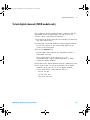
List of Test Equipment
Below is a list of test equipment and accessories required to
perform the performance test verification procedures.
Table 4
List of test equipment
Equipment
Critical Specifications
Recommended Model/
Part Number
Test connector, 8-by-2*
See page 41 for instructions on building test connector.
n/a
Digital Multimeter
0.1 mV resolution, 0.005% accuracy
Agilent 34401A
Power Splitter
Outputs differ by 0.15 dB
Agilent 11667B
Oscilloscope Calibrator
DC offset voltage of -5.5 V to 35.5 V, 0.1 V resolution
Fluke 5820A
Signal Generator
25 MHz, 100 MHz, 300 MHz, 500 MHz, and 1 GHz
sine waves
Agilent E4400B or
Agilent 8648A
Power Meter/Sensor
1 GHz ±3% accuracy
Agilent E4418B/8482A
Oscilloscope Calibrator
25 MHz—500 MHz sine wave, 5 ppm
Fluke 5820A
BNC banana cable
Agilent 11001-66001
BNC cable (qty 3)
Agilent 10503A
Cable
Type N (m) 609.6 mm (24 in.)
Agilent 11500B
Probe cable*
Agilent 01650-61607
Shorting Cap BNC
Agilent 1250-0774
Adapter
BNC(f) to banana(m)
Agilent 1251-2277
Adapter
BNC Tee (m) (f) (f)
Agilent 1250-0781
Adapter
Type N (m) to BNC (m)
Agilent 1250-0082
or Pomona 3288 with
Pomona 3533
Blocking capacitor
Agilent 10240-60001
Adapter (qty 3)
N(m) to BNC(f)
Agilent 1250-0780
Feedthrough (qty 2)
50Ω BNC (f) to BNC (m)
Agilent 0960-0301
* Required only for testing digital channels of oscilloscopes that have the MSO option.
Some parts and equipment are available at www.agilent.com or www.parts.agilent.com.
40
6000 Series Oscilloscopes Service Guide
6000_series_service_guide.book Page 41 Friday, March 23, 2007 2:43 PM
Testing Performance
2
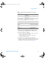
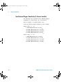
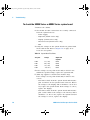
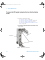
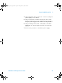
To construct the test connector (for use with MSO models only)
Agilent 6000 Series Oscilloscopes that have digital channels
enabled require the test connector described below. Follow
the steps to build the test connector.
Table 5
Materials required to construct the test connectors
Description
Recommended Part
Qty
BNC (f) Connector
Agilent 1250-1032 or
Pomona 4578
1
Berg Strip, 8-by-2
1
Jumper wire
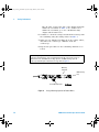
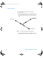
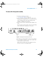
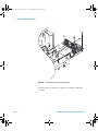
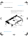
1 Obtain a BNC connector and an 8- by- 2 section of Berg
strip.
2 On one side of the Berg strip, solder a jumper wire to all
of the pins (shown in Figure 1 on page 42).
3 On the other side of the Berg strip, solder another jumper
wire to all of the pins.
4 Solder the center of the BNC connector to a center pin on
one of the rows on the Berg strip.
5 Solder the ground tab of the BNC connector to a center
pin on the other row on the Berg strip.
6000 Series Oscilloscopes Service Guide
41
6000_series_service_guide.book Page 42 Friday, March 23, 2007 2:43 PM
2
Testing Performance
Jumper (2)
Ground Lead
(from analyzer probe)
Signal Lead
(from analyzer probe)
8 x 2 Berg Strip
BNC Panel Mount Connector
Figure 1
42
Constructing the 8-by-2 Connector
6000 Series Oscilloscopes Service Guide
6000_series_service_guide.book Page 43 Friday, March 23, 2007 2:43 PM
Testing Performance
2
To test digital channels (MSO models only)
The acquisition system testing provides confidence that the
acquisition system is functioning correctly. It does not,
however, check a particular specification.
1 Disconnect all probes from the circuit under test and from
any other input source.
2 Using probe leads and grabbers, connect digital channels
D0, D1, D2, and D3 to the Probe Comp signal on the
center of the front panel.
3 Press the AutoScale key.
If four square waves appear, the acquisition system is
functioning correctly.
If the square waves do not appear, go to the
“Troubleshooting” chapter. Then return here to finish
testing the digital channels.
4 Disconnect the digital channels from the calibration point.
5 Use steps 2 and 3 to test the following sets of digital
channels. After you test one set of digital channels,
remove them before connecting the next set.
• D4, D5, D6, D7
• D8, D9, D10, D11
• D12, D13, D14, D15
6000 Series Oscilloscopes Service Guide
43
6000_series_service_guide.book Page 44 Friday, March 23, 2007 2:43 PM
2
Testing Performance
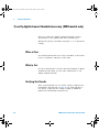
To verify digital channel threshold accuracy (MSO models only)
This test verifies the digital channel threshold accuracy
specification of the Agilent 6000 Series Oscilloscopes.
Threshold accuracy test limits= ±(100 mV + 3% of threshold
setting)
When to Test
You should perform this test every 12 months or after 2000
hours of operation, whichever comes first.
What to Test
Use these instructions to test the threshold settings of digital
channels D7- D0. Then, use the same instructions to test
digital channels D15- D8.
Verifying Test Results
After each threshold test, record the voltage reading in the
Performance Test Record on page 70. To verify whether a
test passes, verify that the voltage reading is within the
limits in the Performance Test Record.
44
6000 Series Oscilloscopes Service Guide
6000_series_service_guide.book Page 45 Friday, March 23, 2007 2:43 PM
Testing Performance
2
Table 6
Equipment Required to Test Digital Channel Threshold
Accuracy
Equipment
Critical
Specifications
Recommended Model/Part
Digital Multimeter
0.1 mV resolution,
0.005% accuracy
Agilent 34401A
Oscilloscope Calibrator
DC offset voltage
6.3 V
Fluke 5820A
BNC-Banana Cable
Agilent 11001-60001
BNC Tee
Agilent 1250-0781
BNC Cable
Fluke 50Ω cable, P/N 686318
BNC Test Connector,
8-by-2
User-built (See page 41.)
Probe Cable
Agilent 01650-61607
1 Turn on the test equipment and the oscilloscope. Let
them warm up for 30 minutes before starting the test.
2 Set up the oscilloscope calibrator.
a Set the oscilloscope calibrator to provide a DC offset
voltage at the Channel 1 output.
b Use the multimeter to monitor the oscilloscope
calibrator DC output voltage.
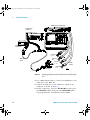
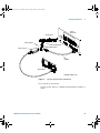
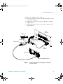
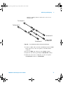
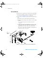
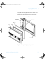
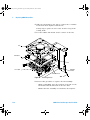
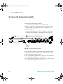
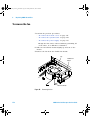
3 Use the 8- by- 2 test connector and the BNC cable
assembly to connect digital channels D0- D7 to one side of
the BNC Tee. Then connect the D0- D7 ground lead to the
ground side of the 8- by- 2 connector. See Figure 2.
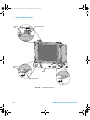
6000 Series Oscilloscopes Service Guide
45
6000_series_service_guide.book Page 46 Friday, March 23, 2007 2:43 PM
2
Testing Performance
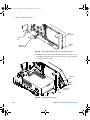
6000L Series Oscilloscope
Oscilloscope
Calibrator
6000A Series Oscilloscope
Digital
Multimeter
BNC Tee
Channels
8 - 15
Channels
0-7
BNC-Banana
cable
Channels
8 - 15
Test
Connector
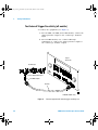
Figure 2
Probe
Cables
Channels
0-7
Setting Up Equipment and Test Connector for the Threshold
Test
4 Use a BNC- banana cable to connect the multimeter to the
other side of the BNC Tee.
5 Connect the BNC Tee to the Channel 1 output of the
calibrator as shown in Figure 2.
6 On the oscilloscope, press the D15 Thru D0 key, then press
the Thresholds softkey, then press the D15 Thru D0 softkey
repeatedly until the check mark is next to User.
46
6000 Series Oscilloscopes Service Guide
6000_series_service_guide.book Page 47 Friday, March 23, 2007 2:43 PM
Testing Performance
2
7 Press the oscilloscope User softkey, then turn the Entry
knob (
) on the front panel on the oscilloscope to set
the threshold test settings as shown in Table 7.
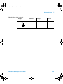
Table 7
Threshold Accuracy Voltage Test Settings
Threshold voltage
setting
(in oscilloscope User
softkey)
DC offset voltage setting
(on oscilloscope
calibrator)
+5.00 V
+5.250 V ±1 mV dc
Lower limit = +4.750 V
Upper limit = +5.250 V
–5.00 V
–4.750 V ±1 mV dc
Lower limit = –5.250 V
Upper limit = –4.750 V
0.00 V
+100m V ±1 mV dc
Upper limit = +100 mV
Lower limit = –100 mV
Limits
8 Do the following steps for each of the threshold voltage
levels shown in Table 7.
a Set the threshold voltage shown in the User softkey
using the Entry knob on the oscilloscope.
b Enter the corresponding DC offset voltage on the
oscilloscope calibrator front panel. Then use the
multimeter to verify the voltage.
Digital channel activity indicators are displayed on the
status line at the top of the oscilloscope display. The
activity indicators for D7- D0 should show all of the
channels at digital high levels.
c Use the knob on the oscilloscope calibrator to decrease
the offset voltage, in increments of 10 mV, until the
activity indicators for digital channels D7- D0 are all at
digital low levels. Record the oscilloscope calibrator
voltage in the Performance Test Record (see page 70).
d Use the knob on the oscilloscope calibrator to increase
the offset voltage, in increments of 10 mV, until the
activity indicators for digital channels D7- D0 are all at
6000 Series Oscilloscopes Service Guide
47
6000_series_service_guide.book Page 48 Friday, March 23, 2007 2:43 PM
2
Testing Performance
digital high levels. Record the oscilloscope calibrator
voltage in the Performance Test Record (see page 70).
Before proceeding to the next step, make sure that you
have recorded the oscilloscope calibrator voltage levels for
each of the threshold settings shown in Table 7.
9 Use the 8- by- 2 test connector to connect digital channels
D15- D8 to the output of the oscilloscope calibrator. Then
connect the D15- D8 ground lead to the ground side of the
8- by- 2 connector.
10 Repeat this procedure (steps 7 and 8) for digital channels
D15- D8 to verify threshold accuracy and record the
threshold levels in the Performance Test Record (see
page 70).
To verify voltage measurement accuracy
This test verifies the accuracy of the analog channel voltage
measurement for each channel (DC Vertical Gain Accuracy
and Dual Cursor Accuracy specifications). In this test, you
will measure the dc voltage output of an oscilloscope
calibrator using dual cursors on the oscilloscope, and
compare the results with the multimeter reading.
Test limits: ±2.0% of full scale ±1 LSB*
• On 300 MHz, 500 MHz, and 1 GHz models, full scale is
defined as 32 mV on the 2 mV/div range.
• On 100 MHz models full scale is defined as 16 mV on the
1 mV/div range.
• Full scale on all other ranges is defined as 8 divisions
times the V/div setting.
*1 LSB = 0.4% of full scale
48
6000 Series Oscilloscopes Service Guide
6000_series_service_guide.book Page 49 Friday, March 23, 2007 2:43 PM
Testing Performance
Table 8
2
Equipment Required to Verify Voltage Measurement Accuracy
Equipment
Critical Specifications
Recommended
Model/Part
Oscilloscope
Calibrator
14 mV to 35 Vdc,
0.1 V resolution
Fluke 5820A
Digital multimeter
Better than 0.01% accuracy
Agilent 34401A
Cable
BNC, Qty 2
Agilent 10503A
Shorting cap
BNC
Agilent 1250-0774
Adapter
BNC (f) to banana (m)
Agilent 1251-2277
Adapter
BNC tee (m) (f) (f)
Agilent 1250-0781
Blocking capacitor
Agilent 10240B
1 Set up the oscilloscope.
a Adjust the channel 1 position knob to place the
baseline at 0.5 major division from the bottom of the
display.
b Set the Volts/Div setting to the value in the first line in
Table 9.
6000 Series Oscilloscopes Service Guide
49
6000_series_service_guide.book Page 50 Friday, March 23, 2007 2:43 PM
2
Testing Performance
Table 9
Settings Used to Verify Voltage Measurement Accuracy
Volts/Div Setting
Oscilloscope
Calibrator Setting
Test Limits
5 V/Div
35 V
34.04 V
to
35.96 V
2 V/Div
14 V
13.616 V
to
14.384 V
1 V/Div
7V
6.808 V
to
7.192 V
500 mV/Div
3.5 V
3.404 V
to
3.596 V
200 mV/Div
1.4 V
1.3616 V
to
1.4384 V
100 mV/Div
700 mV
680.8 mV
to
719.2 mV
50 mV/Div
350 mV
340.4 mV
to
359.6 mV
20 mV/Div
140 mV
136.16 mV
to
143.84 mV
10 mV/Div
70 mV
68.08 mV
to
71.92 mV
5 mV/Div
35 mV
34.04 mV
to
35.96 mV
13.232 mV
to
14.768 mV
14 mV
13.616 mV
to
14.384 mV
7 mV
6.616 mV
to
7.384 mV
2 mV/Div1 (for 1 GHz, 500 MHz, and 300 MHz models)
14 mV
2 mV/Div (for 100 MHz models)
1 mV/Div2
1
Full scale is defined as 32 mV on the 2 mV/div range for 300 MHz, 500 MHz, and 1 GHz models.
2
Full scale is defined as 16 mV on the 1 mV/div range for 100 MHz models.
Full scale on all other ranges is defined as 8 divisions times the V/div setting.
c Press the Acquire key. Then press the Averaging softkey
and set #Avgs to 64.
Wait a few seconds for the measurement to settle.
2 Press the Cursors key, set the Mode softkey to Normal, then
press the X Y softkey and select Y. Press the Y1 softkey,
then use the Entry knob (labeled
on the front panel)
to set the Y1 cursor on the baseline of the signal.
50
6000 Series Oscilloscopes Service Guide
6000_series_service_guide.book Page 51 Friday, March 23, 2007 2:43 PM
Testing Performance
2
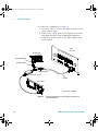
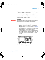
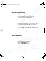
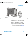
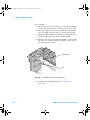
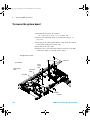
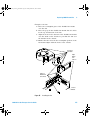
3 Use the BNC tee and cables to connect the oscilloscope
calibrator /power supply to both the oscilloscope and the
multimeter (see Figure 3).
Oscilloscope
Oscilloscope
Calibrator
Digital
Multimeter
BNC Tee
BNC (f) to dual
banana
Figure 3
Connect equipment for voltage measurement accuracy test
4 Adjust the output so that the multimeter reading displays
the first Volts/div calibrator setting value in Table 9.
Wait a few seconds for the measurement to settle.
5 Press the Y2 softkey, then position the Y2 cursor to the
center of the voltage trace using the Entry knob.
6000 Series Oscilloscopes Service Guide
51
6000_series_service_guide.book Page 52 Friday, March 23, 2007 2:43 PM
2
Testing Performance
The ∆Y value on the lower line of the display should be
within the test limits of Table 9. If a result is not
within the test limits, go to the “Troubleshooting”
chapter. Then return here.
6 Continue to check the voltage measurement accuracy with
the remaining Volts/div setting values in Table 9.
7 When you are finished checking all of the voltage values,
disconnect the oscilloscope calibrator from the
oscilloscope.
8 Repeat this procedure for the remaining channels to be
tested.
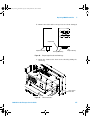
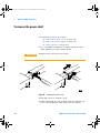
Use a Blocking Capacitor to Reduce Noise
On the more sensitive ranges, such as 2 mV/div and 5 mV/div, noise may be a factor. To
eliminate the noise, add a BNC Tee, blocking capacitor, and BNC shorting cap at the
oscilloscope channel input to shunt the noise to ground. See Figure 4.
Blocking
Capacitor
BNC shorting
cap
To oscilloscope input
Figure 4
52
Using a Blocking Capacitor to Reduce Noise
6000 Series Oscilloscopes Service Guide
6000_series_service_guide.book Page 53 Friday, March 23, 2007 2:43 PM
Testing Performance
2
To verify bandwidth
This test checks the bandwidth of the oscilloscope. In this
test you will use a signal generator and a power meter.
1 GHz Models
Test limits at 2 mV/div to 5 V/div
• All channels (±3 dB)
• dc to 1 GHz
500 MHz Models
Test limits at 2 mV/div to 5 V/div
• All channels (±3 dB)
• dc to 500 MHz
300 MHz Models
Test limits at 2 mV/div to 5 V/div
• All channels (±3 dB)
• dc to 300 MHz
100 MHz Models
Test limits at 1 mV/div to 5 V/div
• All channels (±3 dB)
• dc to 100 MHz
6000 Series Oscilloscopes Service Guide
53
6000_series_service_guide.book Page 54 Friday, March 23, 2007 2:43 PM
2
Testing Performance
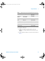
Table 10
Equipment Required to Verify Bandwidth
Equipment
Critical Specifications
Recommended
Model/Part
Signal Generator
100 kHz - 1 GHz at 200 mVrms
Agilent E4400B/8648A
Power Meter/Sensor
1 MHz - 1 GHz ±3% accuracy
Agilent E4418B/8482A
Power Splitter
outputs differ by < 0.15 dB
Agilent 11667A
Cable
Type N (m) 24 inch
Agilent 11500B
Adapter
Type N (m) to BNC (m)
Agilent 1250-0082
Feedthrough
50Ω BNC (f) to BNC (m)
Agilent 0960-0301
1 Connect the equipment (see Figure 5).
a Use the N cable to connect the signal generator to the
input of the power splitter input.
b Connect the power sensor to one output of the power
splitter.
c For 300 MHz, 500 MHz, and 1 GHz oscilloscope models
use an N- to- BNC adapter to connect the other splitter
output to the channel 1 input.
d For 100 MHz oscilloscopes, use an N- to- BNC adapter
and 50Ω feedthrough termination to connect the other
splitter output to the channel 1 input on the
oscilloscope.
54
6000 Series Oscilloscopes Service Guide
6000_series_service_guide.book Page 55 Friday, March 23, 2007 2:43 PM
Testing Performance
2
Signal
Generator
Oscilloscope
Power Splitter
50Ω Feedthrough*
N to BNC adapter
Power Sensor
N Cable
Power Meter
* 100 MHz models only.
Figure 5
Connect equipment for bandwidth test
2 Set up the power meter.
Set the power meter to display measurements in units of
watts.
6000 Series Oscilloscopes Service Guide
55
6000_series_service_guide.book Page 56 Friday, March 23, 2007 2:43 PM
2
Testing Performance
3 Set up the oscilloscope.
a Press the Save/Recall key, then press the Default Setup
softkey.
b Press the Acquire key, then press the Realtime softkey to
unselect Realtime.
c Set channel 1 Coupling to DC.
d On 300 MHz, 500 MHz, and 1 GHz models only, set
channel 1 Imped to 50 Ohm.
e Set the time base to 500 ns/div.
f Set the Volts/Div for channel 1 to 200 mV/div.
g Press the Acquire key, then press the Averaging softkey.
h Turn the Entry knob to set # Avgs to 8 averages.
4 Set the signal generator for 1 MHz and six divisions of
amplitude.
The signal on the oscilloscope screen should be about five
cycles at six divisions amplitude.
5 Set up the Amplitude measurement
a Press the Quick Meas key.
b Press the Clear Meas softkey.
c Press the Select: softkey and use the Entry knob to
select Std Deviation within the select menu.
d Press the Measure Std Dev softkey.
6 Note the oscilloscope Std Dev(1) reading at the bottom of
the screen. (This is the RMS value with any dc offset
removed.)
7 Set the power meter Cal Factor % to the 1 MHz value on
the calibration chart on the power sensor.
8 Note the reading on the power meter and covert to Vrms
using the expression:
Vin 1MHz =
Pmeas1MHz × 50Ω
For example, if the power meter reading is 892 uW, then
Vin1MHz = (892*10- 6 * 50Ω)1/2 = 211.2 mVrms.
56
6000 Series Oscilloscopes Service Guide
6000_series_service_guide.book Page 57 Friday, March 23, 2007 2:43 PM
Testing Performance
2
9 Change the signal generator output frequency according to
the maximum frequency for the oscilloscope using the
following:
• 1 GHz Models: 1 GHz
• 500 MHz Models: 500 MHz
• 300 MHz Models: 300 MHz
• 100 MHz Models: 100 MHz
10 Referencing the frequency from step 9, set the power
meter Cal Factor % to the frequency value on the
calibration chart on the power sensor.
11 Set the oscilloscope sweep speed according to the
following:
• 1 GHz Models: 500 ps/div
• 500 MHz Models: 1 ns/div
• 300 MHz Models: 2 ns/div
• 100 MHz Models: 5 ns/div
12 Note the oscilloscope Std Dev(1) reading at the bottom of
the screen.
13 Note the reading on the power meter and covert to Vrms
using the expression:
Vin max_freq =
Pmeas max freq × 50Ω
14 Calculate the response using the expression:
Vout max freq / Vin max freq
response(dB) = 20 log10
Vout 1 MHz / Vin 1 MHz
Example
If:
Pmeas1_MHz = 892 uW
Std Dev(n) 1MHz = 210.4 mV
Pmeas max_freq = 687 uW
Std Dev(n) max freq = 161.6 mV
6000 Series Oscilloscopes Service Guide
57
6000_series_service_guide.book Page 58 Friday, March 23, 2007 2:43 PM
2
Testing Performance
Then after converting the values from the power meter to
Vrms:
response(dB) = 20 log10 161.6 mV / 185.3 mV = -1.16 dB
210.4 mV/ 211.2 mV
15 The result from step 14 should be between +3.0 dB and
- 3.0 dB. Record the result in the Performance Test Record
(see page 70).
16 Move the power splitter from the channel 1 to the channel
2 input.
17 Turn off the current channel and turn on the next
channel using the channel keys.
18 Repeat steps 3 through 17 for the remaining channels,
setting the parameters of the channel being tested where
appropriate.
To verify horizontal ∆t accuracy
The following test is optional because horizontal ∆t accuracy
is a characteristic, not a specification.
This test verifies the horizontal ∆t accuracy. In this test, you
will use the oscilloscope to measure the output of a time
mark generator.
Test limits: ±0.0015% of reading ±0.1% of full scale ±20 ps
(same channel)
58
6000 Series Oscilloscopes Service Guide
6000_series_service_guide.book Page 59 Friday, March 23, 2007 2:43 PM
Testing Performance
Table 11
2
Equipment Required to Verify Horizontal ∆t Accuracy
Equipment
Critical Specifications
Recommended
Model/Part
Oscilloscope
Calibrator
Stability 5 ppm after 1/2 hour
Fluke 5820A
Cable
BNC, 3 feet
Agilent 10503A
Feedthrough
50Ω BNC (f) to BNC (m)
Agilent 0960-0301
1 Connect the equipment:
a For 300 MHz, 500 MHz, and 1 GHz oscilloscope models,
connect the calibrator output to the oscilloscope
channel 1 input.
b For 100 MHz oscilloscopes, use a 50Ω feedthrough
termination to connect the calibrator output to the
oscilloscope channel 1 input.
2 Set up the signal source.
1 Select Marker on the oscilloscope calibrator.
2 Set the calibrator for 100 µs markers (period = 100 µs).
3 Set up the oscilloscope.
a Set channel 1 Coupling to DC.
b On 1 GHz, 500 MHz and 300 MHz models only, set
channel 1 Imped to 50 Ohm.
c Press the Display key, then set the Vectors softkey to off.
d Press the AutoScale key.
e Set the time base to 20 µs/div.
f Press the Main/Delayed key, then set the Time Ref softkey
to Left.
g Adjust the Trigger Level knob to obtain a stable
display.
4 Press the Quick Meas softkey, set the Source softkey to 1,
then press Select and choose Period. Press the Measure
softkey and measure the following:
Period 100 µs — The test limits are 99.8 µs to 100.2 µs.
6000 Series Oscilloscopes Service Guide
59
6000_series_service_guide.book Page 60 Friday, March 23, 2007 2:43 PM
2
Testing Performance
If the measurements are not within the test limits, go to
the “Troubleshooting” chapter. Then return here.
5 Change the calibrator to 100 ns markers. Change the time
base to 20 ns/div. Adjust the trigger level to obtain a
stable display.
6 Measure the following. If the measurements are not within
the test limits, go to the “Troubleshooting” chapter. Then
return here.
Period 100 ns— The test limits are 99.8 ns to 100.2 ns.
7 Change the time base and calibrator markers as follows:
a On 300 MHz, 500 MHz, and 1 GHz models, change time
base to 2 ns/div and the calibrator to 5 ns markers
b On 100 MHz models, change time base to 5 ns/div and
the calibrator to 10 ns markers
8 Make the following measurements. If the measurements
are not within the test limits, go to the “Troubleshooting”
chapter. Then return here.
a For 300 MHz, 500 MHz, and 1 GHz models, period 5 ns
— the test limits are 4.96 ns to 5.04 ns.
b For 100 MHz models, period 10 ns — the test limits are
9.93 ns to 10.07 ns.
To verify trigger sensitivity
This test verifies the trigger sensitivity. In this test, you will
apply a sine wave to the oscilloscope at the upper
bandwidth limit. You will then decrease the amplitude of the
signal to the specified levels, and check to see if the
oscilloscope is still triggered.
The internal trigger sensitivity test is mandatory because it
is a specification. The external trigger test is optional
because it is a characteristic, not a specification.
60
6000 Series Oscilloscopes Service Guide
6000_series_service_guide.book Page 61 Friday, March 23, 2007 2:43 PM
Testing Performance
2
Test limits for:
• Internal trigger on all models:
• < 10 mV/div: greater of 1 div or 5 mVpp
>=10 mV/div: 0.6 div
• External trigger on all 2- channel models
(DSO/MSO6xx2A):
• Trigger range: 1.0V
DC to 100 MHz: < 100 mVpp
>100 MHz to max bandwidth: < 200 mVpp
• Trigger range: 8.0V
DC to 100 MHz: < 250 mVpp
>100 MHz to max bandwidth: < 500 mVpp
• External trigger on 4- channel models:
4- channel 1 GHz, 500 MHz, and 300 MHz models:
(MSO/DSO6104A/6054A/6034A, DSO6104L/6054L)
DC to 500 MHz: < 500 mVpp
4- channel 100 MHz models:
(MSO/DSO6014A, DSO6014L)
DC to 100 MHz: < 500 mVpp
Table 12
Equipment Required to Verify Trigger Sensitivity
Equipment
Critical Specifications
Recommended Model/Part
Signal
Generator
25-MHz, 100-MHz, 300-MHz,
500-MHz, and 1 GHz sine
waves
Agilent E4400B/8648A
Power splitter
Outputs differ < 0.15 dB
Agilent 11667A
Cable
BNC, Qty 3
Agilent 10503A
Adapter
N (m) to BNC (f), Qty 3
Agilent 1250-0780
Feedthrough
50Ω BNC (f) to BNC (m) Qty 2
Agilent 0960-0301
6000 Series Oscilloscopes Service Guide
61
6000_series_service_guide.book Page 62 Friday, March 23, 2007 2:43 PM
2
Testing Performance
Test Internal Trigger Sensitivity (all models)
1 Connect the equipment (see Figure 6).
a For 300 MHz, 500 MHz, and 1 GHz models, connect the
signal generator output to the oscilloscope channel 1
input.
b For 100 MHz models, use a 50Ω feedthrough
termination to connect the signal generator output to
the oscilloscope channel 1 input.
Signal
Generator
Oscilloscope
50Ω Feedthrough*
N to BNC adapter
N Cable
* 100 MHz models only.
Figure 6
62
Connect equipment for internal trigger sensitivity test
6000 Series Oscilloscopes Service Guide
6000_series_service_guide.book Page 63 Friday, March 23, 2007 2:43 PM
Testing Performance
2
2 Verify the trigger sensitivity at maximum bandwidth.
1 GHz models: 1 GHz
500 MHz models: 500 MHz
300 MHz models: 300 MHz
100 MHz models: 100 MHz
a Press the Save/Recall key, then press the Default Setup
softkey.
b On 300 MHz, 500 MHz, and 1 GHz models, set channel
1 Imped to 50 Ohm.
c Set the output frequency of the signal generator to the
maximum bandwidth of the oscilloscope and set the
amplitude to about 10 mVpp.
d Press the AutoScale key.
e Set the time base to 10 ns/div.
f Set channel 1 to 5 mV/div.
g Decrease the amplitude from the signal generator until
1 vertical division of the signal is displayed.
The trigger is stable when the displayed waveform is
stable. If the trigger is not stable, try adjusting the
trigger level. If adjusting the trigger level makes the
trigger stable, the test still passes. If adjusting the
trigger does not help, see the "Troubleshooting" chapter.
Then return here.
h Record the result as Pass or Fail in the Performance
Test Record (see page 70).
3 Repeat this procedure for the remaining oscilloscope
channels.
6000 Series Oscilloscopes Service Guide
63
6000_series_service_guide.book Page 64 Friday, March 23, 2007 2:43 PM
2
Testing Performance
Test External Trigger Sensitivity (2-channel models)
The following test is optional because External Trigger
Sensitivity is a characteristic, not a specification.
This test applies to 2- channel models only.
Verify the external trigger sensitivity at these settings:
Trigger range = +/- 1 V
• 1 GHz (MSO/DSO6102A), 200 mVpp
• 500 MHz (MSO/DSO6052A), 200 mVpp
• 300 MHz (MSO/DSO6032A), 200 mVpp
• 100 MHz (MSO/DSO6012A), 200 mVpp
Trigger range = +/- 8 V
• 1 GHz (MSO/DSO6102A), 500 mVpp
• 500 MHz (MSO/DSO6052A), 500 mVpp
• 300 MHz (MSO/DSO6032A), 500 mVpp
• 100 MHz (MSO/DSO6012A), 500 mVpp
64
6000 Series Oscilloscopes Service Guide
6000_series_service_guide.book Page 65 Friday, March 23, 2007 2:43 PM
Testing Performance
2
1 Connect the equipment (see Figure 7).
a Use the N cable to connect the signal generator to the
power splitter input.
b Connect one output of the power splitter to the Ext
Trigger input.
c Connect the power sensor to the other output of the
power splitter.
Signal
Generator
Oscilloscope
Power Splitter
50Ω Feedthrough*
N to BNC adapter
Power Sensor
N Cable
Power Meter
* Required for 100 MHz models.
Figure 7
6000 Series Oscilloscopes Service Guide
Connect equipment for external trigger sensitivity test
(2-channel models)
65
6000_series_service_guide.book Page 66 Friday, March 23, 2007 2:43 PM
2
Testing Performance
2 Set up the oscilloscope.
a Press the Save/Recall key, then press the Default Setup
softkey.
b On 300 MHz, 500 MHz, and 1 GHz models, set the
External Trigger impedance to 50 Ohm. 100 MHz models
do not have this option, so you need to use a 50 ohm
feedthrough terminator as shown in Figure 7.
c Change the trigger Mode from Auto to Normal.
d Use the Range softkey and the Entry knob to set the
range to 1.0 V.
3 Verify the trigger sensitivity at maximum frequency.
a Change the signal generator output frequency:
MSO/DSO6102A: 1 GHz
MSO/DSO6052A: 500 MHz
MSO/DSO6032A: 300 MHz
MSO/DSO6012A: 100 MHz
b Set the power meter Cal Factor % to the appropriate
value (100, 300, 500 MHz or 1 GHz) on the calibration
chart on the power sensor. If necessary, do a linear
interpolation if the correct factor is not included in the
power meter’s calibration chart.
c Adjust the signal generator output for a reading on the
power meter of 100µW. (200 mVpp = 70.71mV rms,
Power = Vin2/50Ω = 70.71 mV2/50Ω = 100µW.)
d Press the Trigger Edge key, then press the Source
softkey to set the trigger source to external trigger.
e Check for stable triggering and adjust the trigger level
if necessary. Triggering is indicated by the Trig’d
indicator at the top of the display. When it is flashing,
the oscilloscope is not triggered. When it is not
flashing, the oscilloscope is triggered.
f Record the results as Pass or Fail in the Performance
Test Record (see page 70).
If the test fails, see the "Troubleshooting" chapter. Then
return here.
66
6000 Series Oscilloscopes Service Guide
6000_series_service_guide.book Page 67 Friday, March 23, 2007 2:43 PM
Testing Performance
2
4 Verify the trigger sensitivity at maximum frequency for
trigger range of 8.0 V.
a Press the Mode/Coupling key, press the External softkey,
then press the Range softkey and use the Entry knob to
set the range to 8.0 V.
b Adjust the signal generator output for reading on the
power meter of 625µW. (500mVpp = 176.78mV rms,
Power = Vin2/50Ω = 176.78 mV2/50Ω = 625µW.)
c Check for stable triggering and adjust the trigger level
if necessary. Triggering is indicated by the Trig’d
indicator at the top of the display. When it is flashing,
the oscilloscope is not triggered. When it is not
flashing, the oscilloscope is triggered.
d Record the results as Pass or Fail in the Performance
Test Record (see page 70).
Test External Trigger Sensitivity (4-channel models)
The following test is optional because External Trigger
Sensitivity is a characteristic, not a specification.
This test applies to 4- channel models only.
Verify the external trigger sensitivity at these settings:
• 1 GHz, 500 MHz, and 300 MHz bandwidth models:
500 MHz, 500 mVpp
• 100 MHz bandwidth models:
100 MHz, 500 mVpp
6000 Series Oscilloscopes Service Guide
67
6000_series_service_guide.book Page 68 Friday, March 23, 2007 2:43 PM
2
Testing Performance
1 Connect the equipment (see Figure 8).
a Use the N cable to connect the signal generator to the
power splitter input.
b Connect one output of the power splitter to the Aux
Trig input through a 50Ω feedthrough termination.
c Connect the power sensor to the other output of the
power splitter.
Signal
Generator
Oscilloscope
50Ω Feedthrough*
N to BNC adapter
Power Splitter
Power Sensor
N Cable
Power Meter
* Required for all models.
Figure 8
68
Connect equipment for external trigger sensitivity test
(4-channel models)
6000 Series Oscilloscopes Service Guide
6000_series_service_guide.book Page 69 Friday, March 23, 2007 2:43 PM
Testing Performance
2
2 Set up the oscilloscope.
a Press the Save/Recall key, then press the Default Setup
softkey.
3 Change the signal generator output frequency as follows:
• For 300 MHz, 500 MHz, and 1 GHz models, set the
signal generator output frequency to 500 MHz
• For 100 MHz models, set the signal generator output
frequency to 100 MHz
4 Set the power meter Cal Factor % to the appropriate
value (500 MHz or 100 MHz) on the calibration chart on
the power sensor. If necessary, do a linear interpolation if
a 500 MHz or 100 MHz factor is not included in the
power meter’s calibration chart.
5 Adjust the signal generator output for reading on the
power meter of 625µW. (500mVpp = 176.78mV rms, Power
= Vin2/50Ω = 176.78 mV2/50Ω = 625µW.)
6 Press the Trigger Edge key, then press the Source softkey
to set the trigger source to External.
7 Check for stable triggering and adjust the trigger level if
necessary. Triggering is indicated by the Trig’d indicator at
the top of the display. When it is flashing, the
oscilloscope is not triggered. When it is not flashing, the
oscilloscope is triggered.
8 Record the results as Pass or Fail in the Performance Test
Record (see page 70).
If the test fails, see the "Troubleshooting" chapter. Then
return here.
6000 Series Oscilloscopes Service Guide
69
6000_series_service_guide.book Page 70 Friday, March 23, 2007 2:43 PM
2
Testing Performance
Agilent 6000 Series Oscilloscopes Performance Test Record
Serial No. ______________________________________
Test Interval ____________________________________
Recommended Next Testing ________________________
Test by _____________________________
Work Order No. ______________________
Temperature ____________
Threshold
Accuracy Test
(100 mV + 3% of
threshold setting)
Limits
4.750 V
5.250 V
-5.250 V
-4.750 V
-100 mV
100 mV
Ch D7-D0
________
________
________
________
________
________
Ch D15-D8
________
________
________
________
________
________
Test Limits
34.04 V to 35.96 V
13.616 V to 14.384 V
6.808 V to 7.192 V
3.404 V to 3.596 V
1.3616 V to 1.4384 V
680.8 mV to 719.2 mV
340.4 mV to 359.6 mV
136.16 mV to 143.84 mV
68.08 mV to 71.92 mV
34.04 mV to 35.96 mV
Channel 1
________
________
________
________
________
________
________
________
________
________
Channel 2
________
________
________
________
________
________
________
________
________
________
13.232 mV to 14.768 mV
________ ________ ________ ________
13.616 mV to 14.384 mV
________ ________ ________ ________
6.616 mV to 7.384 mV
________ ________ ________ ________
Test Limits
3 dB at 1 GHz
3 dB at 500 MHz
3 dB at 300 MHz
3 dB at 100 MHz
Channel 1
________
________
________
________
Specification
5 V - 250 mV
5 V + 250 mV
-5 V - 250 mV
-5 V + 250 mV
0 V - 100 mV
0 V + 100 mV
Voltage Measurement Accuracy
Range
Power Supply Setting
5 V/Div
35 V
2 V/Div
14 V
1 V/Div
7V
500 mV/Div
3.5 V
200 mV/Div
1.4 V
100 mV/Div
700 mV
50 mV/Div
350 mV
20 mV/Div
140 mV
10 mV/Div
70 mV
5 mV/Div
35 mV
2 mV/Div (300 MHz, 500 MHz, and 1 GHz models)
14 mV
2 mV/Div (100 MHz models)
14 mV
1 mV/Div (MSO/DSO6012A)
7 mV
Bandwidth
70
Model
610x
605x
603x
601x
Channel 2
________
________
________
________
Channel 3*
________
________
________
________
________
________
________
________
________
________
Channel 3*
________
________
________
________
Channel 4*
________
________
________
________
________
________
________
________
________
________
Channel 4*
________
________
________
________
6000 Series Oscilloscopes Service Guide
6000_series_service_guide.book Page 71 Friday, March 23, 2007 2:43 PM
Testing Performance
Horizontal ∆t Accuracy
Generator Setting
Period
100 µs
Period
100 ns
Period
10 ns1
Period
5 ns2
2
Test Limits
99.8 µs to 100.2 µs
99.8 ns to 100.2 ns
9.93 ns to 10.07 ns
4.96 ns to 5.04 ns
Results
________
________
________
________
Test Limits
Channel 1 Channel 2 Channel 3* Channel 4*
1 division at 25 MHz
0.6 division at 1 GHz
0.6 division at 500 MHz
0.6 division at 300 MHz
0.6 division at 100 MHz
________
________
________
________
________
1
100 MHz models
2
300 MHz, 500 MHz, and 1 GHz models
Trigger Sensitivity
Internal trigger
1 GHz models
500 MHz models
300 MHz models
100 MHz models
Trigger Sensitivity
Test Limits
External trigger (6102A, 6052A, 6032A, 6012A)
± 1 V range:
100 mV at 25 MHz
6102A
200 mV at 1 GHz
6052A
200 mV at 500 MHz
6032A
200 mV at 300 MHz
6012A
200 mV at 100 MHz
________
________
________
________
________
________
________
________
________
________
________
_______
_______
_______
_______
Channel 1 Channel 2 Channel 3* Channel 4*
________
________
________
________
________
________
________
________
________
________
________
________
________
________
________
________
________
________
________
________
External trigger (6102A, 6052A, 6032A, 6012A)
± 8 V range:
250 mV at 25 MHz
6102A
500 mV at 1 GHz
6052A
500 mV at 500 MHz
6032A
500 mV at 300 MHz
6012A
500 mV at 100 MHz
________
________
________
________
________
________
________
________
________
________
________
________
________
________
________
________
________
________
________
________
External trigger (6014, 6034A, 6054, 6104)
6104, 6054, 6034
500 mV at 500 MHz
6014
500 mV at 100 MHz
________ ________ ________ ________
________ ________ ________ ________
* Where applicable
6000 Series Oscilloscopes Service Guide
71
6000_series_service_guide.book Page 72 Friday, March 23, 2007 2:43 PM
2
72
Testing Performance
6000 Series Oscilloscopes Service Guide
6000_series_service_guide.book Page 73 Friday, March 23, 2007 2:43 PM
Agilent 6000 Series Oscilloscopes
Service Guide
3
Calibrating and Adjusting
User Calibration 75
This chapter explains how to adjust the oscilloscope for
optimum operating performance. You should perform
self- calibration according to the following recommendations:
• Every 12 months or after 2000 hours of operation
• If the ambient temperature is >10 °C from the calibration
temperature
• If you want to maximize the measurement accuracy
The amount of use, environmental conditions, and
experience with other instruments help determine if you
need shorter adjustment intervals.
Let the Equipment Warm Up Before Adjusting
Before you start the adjustments, let the oscilloscope and
test equipment warm up for at least 30 minutes.
Read All Cautions and Warnings
Read the following cautions and warning before making
adjustments or performing self- calibration.
WA R N I N G
HAZARDOUS VOLTAGES!
Read the safety notice at the front of this book before proceeding.
Maintenance is performed with power supplied to the oscilloscope and with the
protective covers removed. Only trained service personnel who are aware of the
hazards involved should perform the maintenance. Whenever possible, perform the
procedures with the power cord removed from the oscilloscope.
Agilent Technologies
73
6000_series_service_guide.book Page 74 Friday, March 23, 2007 2:43 PM
3
Calibrating and Adjusting
CAUTION
CAUTION
CAUTION
74
REMOVE POWER TO AVOID DAMAGE!
Do not disconnect any cables or remove any assemblies with power applied to the
oscilloscope. Otherwise, damage to the oscilloscope can occur.
USE EXTERNAL FAN TO REDUCE TEMPERATURE!
When you must operate the oscilloscope with its cover and main shield removed,
use an external fan to provide continuous air flow over the samplers (the ICs with
heat sinks on them). Air flow over the samplers is reduced when the cover and
main shield is removed, which leads to higher than normal operating temperatures.
Have the fan blow air across the system board where the heat sinks are located. If
the cover is removed but the main shield remains installed and the bottom holes
are not blocked, the instrument will cool properly.
AVOID DAMAGE TO ELECTRONIC COMPONENTS!
Electrostatic discharge (ESD) can damage electronic components. When you use
any of the procedures in this chapter, use proper ESD precautions. As a minimum,
place the oscilloscope on a properly grounded ESD mat and wear a properly
grounded ESD strap.
6000 Series Oscilloscopes Service Guide
6000_series_service_guide.book Page 75 Friday, March 23, 2007 2:43 PM
Calibrating and Adjusting
3
User Calibration
Perform user- calibration:
• Each year or after 2000 hours of operation.
• If the ambient temperature is >10° C from the calibration
temperature.
• If you want to maximize the measurement accuracy.
The amount of use, environmental conditions, and
experience with other instruments help determine if you
need shorter User Cal intervals.
User Cal performs an internal self- alignment routine to
optimize the signal path in the oscilloscope. The routine uses
internally generated signals to optimize circuits that affect
channel sensitivity, offset, and trigger parameters. Disconnect
all inputs and allow the oscilloscope to warm up before
performing this procedure.
Performing User Cal will invalidate your Certificate of
Calibration. If NIST (National Institute of Standards and
Technology) traceability is required perform the procedures
in Chapter 2 in this book using traceable sources.
To perform User Cal
1 Set the rear- panel CALIBRATION switch to
UNPROTECTED.
2 Connect short (12 inch maximum) equal length cables to
each analog channel’s BNC connector on the front of the
oscilloscope. You will need two equal- length cables for a
2- channel oscilloscope or four equal- length cables for a
4- channel oscilloscope.
6000 Series Oscilloscopes Service Guide
75
6000_series_service_guide.book Page 76 Friday, March 23, 2007 2:43 PM
3
Calibrating and Adjusting
Use 50Ω RG58AU or equivalent BNC cables when
performing User Cal.
a For a 2- channel oscilloscope, connect a BNC tee to the
equal length cables. Then connect a BNC(f)- to- BNC(f)
(also called a barrel connector) to the tee as shown
below.
Longer cable
to TRIG OUT
To Channel 1
To Channel 2
Figure 9
User Calibration cable for 2-channel oscilloscope
b For a 4- channel oscilloscope, connect BNC tees to the
equal- length cables as shown below. Then connect a
76
6000 Series Oscilloscopes Service Guide
6000_series_service_guide.book Page 77 Friday, March 23, 2007 2:43 PM
Calibrating and Adjusting
3
BNC(f)- to- BNC(f) (barrel connector) to the tee as
shown below.
To Channel 1
To Channel 2
To Channel 3
To Channel 4
Figure 10
Longer cable
to TRIG OUT
User Calibration cable for 4-channel oscilloscope
3 Connect a BNC cable (40 inches maximum) from the TRIG
OUT connector on the rear panel to the BNC barrel
connector.
4 Press the Utility key, then press the Service softkey.
5 Begin the Self Cal by pressing the Start User Cal softkey.
6 When the User Cal is completed, set the rear- panel
CALIBRATION switch to PROTECTED.
6000 Series Oscilloscopes Service Guide
77
6000_series_service_guide.book Page 78 Friday, March 23, 2007 2:43 PM
3
Calibrating and Adjusting
User Cal Status
Pressing the User Cal Status softkey displays the following
summary results of the previous User Cal, and the status of
probe calibrations for probes that can be calibrated. Note
that AutoProbes do not need to be calibrated, but InfiniiMax
can be calibrated.
Results:
User Cal date:
Change in temperature since last User Cal:
Failure:
Comments:
Probe Cal Status:
78
6000 Series Oscilloscopes Service Guide
6000_series_service_guide.book Page 79 Friday, March 23, 2007 2:43 PM
Agilent 6000 Series Oscilloscopes
Service Guide
4
Troubleshooting
Solving General Problems with the Oscilloscope 80
Troubleshooting the Oscilloscope 83
This chapter begins with suggestions for solving general
problems that you may encounter with the oscilloscope. It
tells you what to do in these cases:
• If there is no trace display
• If the trace display is unusual or unexpected
• If you cannot see a channel
• If you cannot get any response from the oscilloscope
Procedures for troubleshooting the oscilloscope follow the
problem solving suggestions. The troubleshooting section
shows you how to:
• Check out the oscilloscope
• Check power supply
• Check the system board
• Check the display
• Check the fan
• Run internal self- tests
• Verify default setup
Read All Cautions and Warnings
Before you begin any troubleshooting, read all Warning and Cautions in the “Troubleshooting”
section.
Agilent Technologies
79
6000_series_service_guide.book Page 80 Friday, March 23, 2007 2:43 PM
4
Troubleshooting
Solving General Problems with the Oscilloscope
This section describes how to solve general problems that
you may encounter while using the Agilent 6000 Series
Oscilloscopes to make measurements.
After troubleshooting the oscilloscope, if you need to replace
parts, refer to the “Replaceable Parts” chapter.
On 6000L Series oscilloscopes, connect an XGA display to
the display port on the rear panel before you begin
troubleshooting. Then connect the oscilloscope to the
network, establish communication, and use the Remote Front
Panel feature described in the 6000 Series Oscilloscopes
User’s Guide to control the oscilloscope. If you do not have
the user’s guide, you can download it from
www.agilent.com/find/mso6000.
If there is no display
✔ Check that the power cord is firmly seated in the
oscilloscope power receptacle.
✔ Check that the power source is live.
✔ Check that the front- panel power switch is on.
✔ If there is still no display, go to the troubleshooting
procedures in this chapter.
If there is no trace display
✔ Check that the INTENSITY knob on the front panel is
adjusted correctly.
✔ Recall the default setup by pressing Save/Recall then
Default Setup. This will ensure that the trigger mode is
Auto.
80
6000 Series Oscilloscopes Service Guide
6000_series_service_guide.book Page 81 Friday, March 23, 2007 2:43 PM
Troubleshooting
4
✔ Check that the probe clips are securely connected to
points in the circuit under test, and that the ground is
connected.
✔ Check that the circuit under test is powered on.
✔ Press the AutoScale key.
✔ Obtain service from Agilent Technologies, if necessary.
If the trace display is unusual or unexpected
✔ Check that the Horizontal time/division setting is correct
for the expected frequency range of the input signals.
✔ The sampling speed of the oscilloscope depends on the
time/division setting. It may be that when time/division is
set to slower speeds, the oscilloscope is sampling too
slowly to capture all of the transitions on the waveform.
Use peak detect mode.
✔ Check that all oscilloscope probes are connected to the
correct signals in the circuit under test.
✔ Ensure that the probe’s ground lead is securely connected
to a ground point in the circuit under test. For
high- speed measurements, each probe’s individual ground
lead should also be connected to a ground point closest to
the signal point in the circuit under test.
✔ Check that the trigger setup is correct.
✔ A correct trigger setup is the most important factor in
helping you capture the data you desire. See the User’s
Guide for information about triggering.
✔ Check that infinite persistence in the Display menu is
turned off, then press the Clear Display softkey.
✔ Press the AutoScale key.
If you cannot see a channel
✔ Recall the default setup by pressing Save/Recall then
Default Setup. This will ensure that the trigger mode is
Auto.
6000 Series Oscilloscopes Service Guide
81
6000_series_service_guide.book Page 82 Friday, March 23, 2007 2:43 PM
4
Troubleshooting
✔ Check that the oscilloscope probe’s BNC connector is
securely attached to the oscilloscope’s input connector.
✔ Check that the probe clips are securely connected to
points in the circuit under test.
✔ Check that the circuit under test is powered on.
You may have pressed the AutoScale key before an input
signal was available.
Performing the checks listed here ensures that the signals
from the circuit under test will be seen by the
oscilloscope. Perform the remaining checks in this topic to
make sure the oscilloscope channels are on, and to obtain
an automatic setup.
✔ Check that the desired oscilloscope channels are turned
on.
a Press the analog channel key until it is illuminated
(6000A Series models) or switch on the analog channel
by selecting Analog from the menu bar of the Remote
Front Panel (6000L Series models).
b Press the digital channels (D15 Thru D0) key until it is
illuminated (6000A Series models with the MSO option)
or switch on the digital channels by selecting Digital
from the menu bar (6000L Series models with the MSO
option). Ensure that the desired channels are turned
on.
✔ Press the AutoScale key to automatically set up all
channels.
82
6000 Series Oscilloscopes Service Guide
6000_series_service_guide.book Page 83 Friday, March 23, 2007 2:43 PM
Troubleshooting
4
Troubleshooting the Oscilloscope
The service policy for the Agilent 6000 Series Oscilloscopes
is assembly level replacement. If you need parts or
assistance from Agilent Technologies to repair your
instrument, go to www.agilent.com and locate the service
facility for your area.
WA R N I N G
WA R N I N G
CAUTION
CAUTION
HAZARDOUS VOLTAGES EXIST — REMOVE POWER FIRST !
The procedures described in this section are performed with power supplied to the
oscilloscope and with the protective covers removed. Only trained service
personnel who are aware of the hazards involved should perform the procedures.
Whenever possible, perform the procedures with the power cord removed from the
oscilloscope. Read the safety notice at the back of this book before proceeding.
HAZARDOUS VOLTAGES EXIST — HIGH VOLTAGE IS PRESENT ON DSO6000L
SERIES POWER SUPPLY HEAT SINKS !
The power supply heat sinks of the 6000L Series oscilloscopes are at a high
potential. This presents an electric shock hazard. Protect yourself from electric
shock by keeping this area covered or by not coming in contact with the heat sinks
when the power cord is attached to the oscilloscope!
REMOVE POWER TO AVOID DAMAGE !
Do not disconnect any cables or remove any assemblies while power is applied to
the oscilloscope, or damage to the oscilloscope can occur.
AVOID ESD DAMAGE TO COMPONENTS !
ELECTROSTATIC DISCHARGE (ESD) can damage electronic components. Use
proper ESD precautions when doing any of the procedures in this chapter. As a
minimum, place the oscilloscope on a properly grounded ESD mat and wear a
properly grounded ESD strap.
6000 Series Oscilloscopes Service Guide
83
6000_series_service_guide.book Page 84 Friday, March 23, 2007 2:43 PM
4
Troubleshooting
Equipment required for troubleshooting
The equipment listed in this table is required to troubleshoot the
oscilloscope.
Table 13
Equipment Required to Troubleshoot the Oscilloscope
Equipment
Critical Specifications
Recommended Model/Part
Digital multimeter
Accuracy ±0.05,% 1 mV resolution
Agilent 34401A
Oscilloscope
Capable of measuring ≥ 500 MHz signal.
1 MΩ input impedance.
Agilent
DSO6102A, MSO6102A,
DSO6102A, or MSO6104A
To check out the oscilloscope
1 Disconnect any external cables from the front panel.
2 Disconnect the power cord, then remove the cabinet
following the instructions on page 104 for Agilent 6000A
Series models or page 145 for Agilent 6000L Series
models.
CAUTION
WA R N I N G
84
USE AN EXTERNAL FAN TO AVOID OVERHEATING COMPONENTS !
When you remove the oscilloscope cover and main shield, use an external fan to
provide continuous air flow over the heat sinks. Air flow over the heat sinks is
reduced when the cover and main shield are removed, which leads to higher than
normal operating temperatures. Have the fan blow air across the system board
where the heat sinks are located. Otherwise, damage to the components can
occur.
If the cover of a 6000A Series oscilloscope is removed but the main shield remains
installed and the bottom holes are not blocked, the instrument will cool properly.
HAZARDOUS VOLTAGES EXIST — HIGH VOLTAGE IS PRESENT ON DSO6000L
SERIES POWER SUPPLY HEAT SINKS !
The power supply heat sinks of the 6000L Series oscilloscopes are at a high
potential. This presents an electric shock hazard. Protect yourself from electric
shock by keeping this area covered or by not coming in contact with the heat sinks
when the power cord is attached to the oscilloscope!
6000 Series Oscilloscopes Service Guide
6000_series_service_guide.book Page 85 Friday, March 23, 2007 2:43 PM
Troubleshooting
4
3 Connect the power cord to the rear of the oscilloscope,
then to a suitable ac voltage source.
The oscilloscope power supply automatically adjusts for
input line voltages in the range of 100 to 240 VAC. Ensure
that you have the correct line cord (see Table 16 on
page 160 or Table 4 on page 169). The power cord provided
is matched to the country of origin.
WA R N I N G
AVOID INJURY.
Always operate the oscilloscope with an approved three conductor power cable.
Do not negate the protective action of the three conductor power cable.
• On 6000A Series models, press the power switch.
• When the oscilloscope is turned on, the front panel
LEDs will light up in the sequence shown in Figure 11
on page 85.
• Next the Agilent logo and advisory screen will appear
on the LCD before the trace display appears.
• It will take about 3 to 4 seconds for the instrument to
turn on. The instrument will go through the basic self
test to make sure all the major hardware is working
correctly.
}4
}3
5
}2
}1
Figure 11
6000 Series Oscilloscopes Service Guide
6000A Series start up sequence
85
6000_series_service_guide.book Page 86 Friday, March 23, 2007 2:43 PM
4
Troubleshooting
• On 6000L Series models, press the power switch.
The Power indicator LED is green. The LAN indicator LED
is bi- color (green and/or red).
• Shortly after pressing the power switch, the power
indicator and LAN indicator will illuminate.
• Both will extinguish.
• Both will illuminate again. If a LAN is connected, the
LAN indicator will illuminate red. It will turn green
when the LAN is connected as it is configured. The
amount of time it takes the indicator to turn green
depends on the network and the oscilloscope’s LAN
configuration setup.
Power Power
Switch Indicator
LAN
Status
Indicator
Reset
Switch
Figure 12
6000L Series LED indicators
4 If the lights illuminate, then the power supply is probably
working correctly.
5 Proceed to “To verify basic oscilloscope operation” on
page 87.
86
6000 Series Oscilloscopes Service Guide
6000_series_service_guide.book Page 87 Friday, March 23, 2007 2:43 PM
Troubleshooting
4
To verify basic oscilloscope operation
For 6000L Series oscilloscopes, connect the oscilloscope to
your network or establish a point- to- point connection, and
use the Remote Front Panel feature described in the 6000
Series Oscilloscopes User’s Guide to control the oscilloscope.
If you do not have the user’s guide, you can download it
from www.agilent.com/find/mso6000.
1 Press the Save/Recall key on the front panel, then press
the Default Setup softkey under the display. The oscilloscope
is now configured to its default settings.
2 Connect an oscilloscope probe from channel 1 to the Probe
Comp signal terminal on the front panel.
3 Connect the probe’s ground lead to the ground terminal
that is next to the Probe Comp terminal.
4 Press AutoScale.
5 You should see a waveform on the oscilloscope’s display
similar to this:
6000 Series Oscilloscopes Service Guide
87
6000_series_service_guide.book Page 88 Friday, March 23, 2007 2:43 PM
4
Troubleshooting
If you see the waveform, but the square wave is not
shaped correctly as shown above, perform the procedure
“To compensate the analog probes” on page 88.
If you do not see the waveform, ensure your power source
is adequate, the oscilloscope is properly powered- on, and
the probe is connected securely to the front- panel analog
channel input BNC and to the Probe Comp terminal.
6 If you still do not see the waveform, use the
troubleshooting flowchart in this chapter to isolate the
problem.
To compensate the analog probes
You should compensate your analog probes to match their
characteristics to the oscilloscope’s channels. A poorly
compensated probe can introduce measurement errors.
1 Perform the procedure “To verify basic oscilloscope
operation” on page 87
2 Use a nonmetallic tool to adjust the trimmer capacitor on
the probe for the flattest pulse possible. The trimmer
capacitor is located on the probe BNC connector.
Perfectly compensated
Over compensated
Under compensated
comp.cdr
Figure 13
88
Example pulses
6000 Series Oscilloscopes Service Guide
6000_series_service_guide.book Page 89 Friday, March 23, 2007 2:43 PM
Troubleshooting
4
3 Connect probes to all other analog channels (channel 2 of
a 2- channel oscilloscope, or channels 2, 3, and 4 of a
4- channel oscilloscope). Repeat the procedure for each
channel. This matches each probe to each channel.
The process of compensating the probes serves as a basic
test to verify that the oscilloscope is functional.
6000 Series Oscilloscopes Service Guide
89
6000_series_service_guide.book Page 90 Friday, March 23, 2007 2:43 PM
4
Troubleshooting
Troubleshooting Flowchart
The following flowchart describes how to troubleshoot 6000A
Series and 6000L Series models.
Start
Test Power Supply
Okay?
No
Replace Power
Supply
No
Replace System
Board
No
Replace Display
Yes
Test System
Board
Okay?
Yes
Test Display
Okay?
Yes
End
90
6000 Series Oscilloscopes Service Guide
6000_series_service_guide.book Page 91 Friday, March 23, 2007 2:43 PM
Troubleshooting
4
To check the 6000A Series oscilloscope power supply
1 Disconnect the power cord from the oscilloscope. Then
remove the oscilloscope cover.
CAUTION
USE AN EXTERNAL FAN TO AVOID OVERHEATING COMPONENTS !
When you remove the oscilloscope cover and main shield, use an external fan to
provide continuous air flow over the heat sinks. Air flow over the heat sinks is
reduced when the cover and main shield are removed, which leads to higher than
normal operating temperatures. Have the fan blow air across the system board
where the heat sinks are located. Otherwise, damage to the components can
occur.
If the cover of a 6000A Series oscilloscope is removed but the main shield remains
installed and the bottom holes are not blocked, the instrument will cool properly.
2 Connect the negative lead of the multimeter to a ground
point on the oscilloscope.
3 Connect the power cord and turn on the oscilloscope.
4 Measure the power supply voltage at J3200, pin 9 on the
system board. See Figure 14 on page 92. The voltage
should be 15 V ±10%.
• If the voltage is not correct, continue to the next step.
• If the voltage is correct, the power supply is good.
6000 Series Oscilloscopes Service Guide
91
6000_series_service_guide.book Page 92 Friday, March 23, 2007 2:43 PM
4
Troubleshooting
J3200
Pin 1
Pin 9
Figure 14
System Board Test Points
5 Disconnect the cable from the system board and check the
voltage between pins 9 & 5 of the connector coming from
the power supply.
6 If it is less than 14 V, the problem is in the cable or the
power supply. Remove the cable and test it for shorts or
opens using the DMM. Replace the defective assembly.
92
6000 Series Oscilloscopes Service Guide
6000_series_service_guide.book Page 93 Friday, March 23, 2007 2:43 PM
Troubleshooting
4
7 If the voltage is 15 V ±10% only when the cable is
disconnected from the system board, then test the system
board.
6000 Series Oscilloscopes Service Guide
93
6000_series_service_guide.book Page 94 Friday, March 23, 2007 2:43 PM
4
Troubleshooting
To check the 6000L Series oscilloscope power supply
WA R N I N G
CAUTION
NOTE
HAZARDOUS VOLTAGES EXIST — HIGH VOLTAGE IS PRESENT ON DSO6000L
SERIES POWER SUPPLY HEAT SINKS !
The power supply heat sinks of the 6000L Series oscilloscopes are at a high
potential. This presents an electric shock hazard. Protect yourself from electric
shock by keeping this area covered or by not coming in contact with the heat sinks
when the power cord is attached to the oscilloscope!
USE AN EXTERNAL FAN TO AVOID OVERHEATING COMPONENTS !
When you remove the oscilloscope cover and main shield, use an external fan to
provide continuous air flow over the heat sinks. Air flow over the heat sinks is
reduced when the cover and main shield are removed, which leads to higher than
normal operating temperatures. Have the fan blow air across the system board
where the heat sinks are located. Otherwise, damage to the components can
occur.
If the power supply fuse is blown, the power supply is defective, and you must
replace it. See the “Replaceable Parts” chapter for information about removing the
power supply.
1 Disconnect the power cord from the oscilloscope. Then
remove the oscilloscope cover.
2 Connect the negative lead of the multimeter to a ground
point on the oscilloscope.
3 Connect the power cord and turn on the oscilloscope.
4 Measure the power supply voltage at J3200, pin 9 on the
system board. See Figure 14 on page 92. The voltage
should be 15 V ±10%. If the voltage is correct, the power
supply is working correctly.
5 If the voltage is not correct:
1 Disconnect the power cord.
2 Remove the fan. See “To remove the fan” on page 152.
3 Disconnect plug J3 from the power supply and from the
system board.
94
6000 Series Oscilloscopes Service Guide
6000_series_service_guide.book Page 95 Friday, March 23, 2007 2:43 PM
Troubleshooting
4
4 Perform a continuity check on the “DC cable” (item W1
on page 167). If the cable is shorted or open, replace
it. If not, continue to the next step.
5 Reconnect the “DC cable” to the power supply, but not
to the system board.
WA R N I N G
HAZARDOUS VOLTAGES EXIST — HIGH VOLTAGE IS PRESENT ON DSO6000L
SERIES POWER SUPPLY HEAT SINKS !
The power supply heat sinks of the 6000L Series oscilloscopes are at a high
potential. This presents an electric shock hazard. Protect yourself from electric
shock by keeping this area covered or by not coming in contact with the heat sinks
when the power cord is attached to the oscilloscope!
6 Connect the power cord and check the power supply
voltage between pins 1 and 6 of the system board side
of the “DC cable”. The voltage should be 15 V ±10%.
• If the voltage is correct, then test the system board
(see page 96).
• If the voltage is not correct, then replace the power
supply
(see page 150).
6000 Series Oscilloscopes Service Guide
95
6000_series_service_guide.book Page 96 Friday, March 23, 2007 2:43 PM
4
Troubleshooting
To check the 6000A Series or 6000L Series system board
1 Remove the cabinet.
2 Check that all cable connections are securely connected
from the system board to:
• Power supply
• Keyboard (6000A Series only)
• Display (6000A Series only)
• Inverter board (6000A Series only)
• Fan
3 Verify the voltages at the system board test points listed
in the table below. Refer to Figure 14 on page 92 to
locate the test points.
Table 14
System Board Test Points
Test point
Voltage
L3204
L3201
L3301
L3302
3.3 (+- 0.1)
5.0 (+- 0.1)
1.5 (+- 0.1)
-5.2 (+- 0.1)
Output from
regulator:
U3202
U3202
U3300
U3301
4 If the voltage at test point L3301 and/or L3302 is not
within the specified range, replace the system board.
5 (This step applies to 6000A Series models only)
If the voltage at test point L3204 and/or L3201 is not
correct:
• Disconnect J2730 from the system board and measure
pins 19 and 20 on the system board connector. This is
the voltage to the display, and it should be 3.3V. If it is
not, replace the system board. If the voltage is correct,
replace the display.
• Disconnect J2750 from the system board and measure
pins 3 and 4. This is the voltage to the inverter, and it
should be 5 V. If it is not, replace the system board. If
the voltage is correct, replace the display.
96
6000 Series Oscilloscopes Service Guide
6000_series_service_guide.book Page 97 Friday, March 23, 2007 2:43 PM
Troubleshooting
4
6 If all cables are properly connected and none of the
previous tests confirm a failure on another assembly,
replace the system board.
To check the 6000A Series display
1 Disconnect the power cord.
2 Check to verify that the backlight inverter cable is
connected.
3 Ensure the display LCD cable is connected.
4 Connect the power cord.
5 Use the DMM to check the Inverter Power voltage (see
table below).
6 If the voltage is incorrect, replace the system board.
7 If the voltage is correct, use an oscilloscope to check the
LCD clock (see table below).
Table 15
Display Signals on the System Board
Inverter Power
Video Signal
Signal
J2750 Pin 3 or 4
J2730 Pin 6 and 7
Normal/Typical Result
5V
480 MHz clock
8 If the clock signal is good, replace the LCD.
9 If the clock signal is absent, replace the system board.
To check the 6000L Series display output
1 Connect a known good external XGA display and
power- up the display and the oscilloscope.
2 If the known good display does show an output from the
XGA port of the oscilloscope, replace the system board.
6000 Series Oscilloscopes Service Guide
97
6000_series_service_guide.book Page 98 Friday, March 23, 2007 2:43 PM
4
Troubleshooting
To check the fan
The fan speed is controlled by a circuit on the system board.
1 If the fan is running, perform the internal self- tests. Go
to “To run the internal self- tests” on page 99.
2 If the fan is not running, it may be defective. Follow these
steps:
a Disconnect the fan cable from the system board.
b Measure the fan voltage at the connector on the system
board.
See the figure below for the location of the fan
connector.
c If the fan voltage is approximately +8.5 Vdc at room
temperature, replace the fan. If the fan voltage is not
approximately +8.5 Vdc, replace the system board.
The proper voltage range depending on temperature is
between +6.0 Vdc to +11.5 Vdc.
Fan
Connector
J3400
Figure 15
98
Location of the Fan Connector (shown on 6000A model)
6000 Series Oscilloscopes Service Guide
6000_series_service_guide.book Page 99 Friday, March 23, 2007 2:43 PM
Troubleshooting
4
To run the internal self-tests
Self Test performs a series of internal procedures to verify
that the oscilloscope is operating properly.
It is recommended that you run the Self Test:
• after experiencing abnormal operation
• for additional information to better describe an
oscilloscope failure
• to verify proper operation after the oscilloscope has been
repaired
Successfully passing Self Test does not guarantee 100% of
the oscilloscope’s functionality. Self Test is designed to
provide an 80% confidence level that the oscilloscope is
operating properly.
1 Press the Utility key, then press the Service softkey. Use
the Remote Front Panel feature if you are testing a 6000L
Series model.
2 Begin the internal self tests by pressing the Start Self Test
softkey.
To verify default setup
The oscilloscope is designed to turn on with the setup from
the last turn on or previous setup. However, if the Secure
Environment option is installed, the oscilloscope will always
execute a Default Setup upon power- up.
To recall the factory default setup:
1 Press the Save/Recall key.
2 Press the Default Setup softkey.
This returns the oscilloscope to its factory default settings
and places the oscilloscope in a known operating
condition. The major default settings are:
• Horizontal - main mode, 100 us/div scale, 0 s delay,
center time reference
6000 Series Oscilloscopes Service Guide
99
6000_series_service_guide.book Page 100 Friday, March 23, 2007 2:43 PM
4
Troubleshooting
• Vertical - Channel 1 on, 5 V/div scale, dc coupling, 0 V
position, probe factor to 1.0 if an AutoProbe probe is
not connected to the channel
• Trigger - Edge trigger, Auto sweep mode, 0 V level,
channel 1 source, dc coupling, rising edge slope, 60 ns
holdoff time
• Display - Vectors on, 20% grid intensity, infinite
persistence off
• Other - Acquire mode normal, Run/Stop to Run, cursor
measurements off
Figure 16
Default setup screen
3 If your screen looks substantially different, replace the
system board.
100
6000 Series Oscilloscopes Service Guide
6000_series_service_guide.book Page 101 Friday, March 23, 2007 2:43 PM
Agilent 6000 Series Oscilloscopes
Service Guide
5
Replacing 6000A Assemblies
To remove the cabinet 104
To remove the handle 105
To remove the storage lid 106
To remove the front panel assembly 107
To remove the keyboard assembly 110
To remove the display assembly 113
To remove the display assembly 113
To remove the backlight inverter board and e-field shield 117
To remove the LCD, gasket, and protective lens from the display
mount 122
To remove the power supply shield 125
To remove the power supply 129
To remove the power shaft 130
To remove the AC input board 131
To remove the batteries (Option BAT only) 133
To remove the battery controller board (Option BAT only) 135
To remove the fan 137
To remove the system board 139
This chapter describes how to remove assemblies from the
Agilent 6000A Series Oscilloscopes. After you have removed
an assembly, to install the replacement assembly, follow the
instructions in reverse order.
The parts shown in the following figures are representative
and may look different than what you have in your
oscilloscope.
Agilent Technologies
101
6000_series_service_guide.book Page 102 Friday, March 23, 2007 2:43 PM
5
Replacing 6000A Assemblies
Tools Used for Disassembly
Use these tools to remove and replace the oscilloscope
assemblies:
• T6, T10, and T20 TORX drivers
• 5/8- inch and 9/32- inch socket drivers
See how the Oscilloscope Parts Fit Together
An exploded view of the oscilloscope is included in the
“Replaceable Parts” chapter. It shows the individual part
numbers used in the assemblies, and shows you how the
parts fit together.
Read All Warnings and Cautions
Read the following warnings and cautions before removing
and replacing any assemblies in the oscilloscope.
WA R N I N G
WA R N I N G
CAUTION
102
HAZARDOUS VOLTAGES!
Read the safety summary at the back of this book before proceeding.
Maintenance is performed with power supplied to the oscilloscope and with the
protective covers removed. Only trained service personnel who are aware of the
hazards involved should perform the maintenance. Whenever possible, perform the
procedures with the power cord removed from the oscilloscope.
AVOID ELECTRICAL SHOCK !
Hazardous voltages exist on the LCD assembly and power supply. To avoid
electrical shock:
1 Disconnect the power cord from the oscilloscope.
2 Wait at least three minutes for the capacitors in the oscilloscope to discharge
before you begin disassembly.
Read the Safety Summary at the back of this manual before you begin.
REMOVE POWER TO AVOID DAMAGE !
Remove power before you begin to remove and replace assemblies. Do not remove
or replace assemblies while the oscilloscope is turned on, or damage to the
components can occur.
6000 Series Oscilloscopes Service Guide
6000_series_service_guide.book Page 103 Friday, March 23, 2007 2:43 PM
Replacing 6000A Assemblies
CAUTION
5
AVOID DAMAGE TO ELECTRONIC COMPONENTS !
ELECTROSTATIC DISCHARGE (ESD) can damage electronic components. When
doing any of the procedures in this chapter, use proper ESD precautions. As a
minimum, you should place the instrument on a properly grounded ESD mat and
wear a properly grounded ESD strap.
6000 Series Oscilloscopes Service Guide
103
6000_series_service_guide.book Page 104 Friday, March 23, 2007 2:43 PM
5
Replacing 6000A Assemblies
To remove the cabinet
1 Turn off the oscilloscope and disconnect the power cable.
2 Using the T20 TORX driver, remove the two screws from
the rear of the cabinet.
3 Using your thumbs, gently push on the rear- panel
connectors to slide the oscilloscope out of the cabinet.
T-20 Screw
Gently push
on the connectors
T-20 Screw
Figure 17
104
Removing the cabinet
6000 Series Oscilloscopes Service Guide
6000_series_service_guide.book Page 105 Friday, March 23, 2007 2:43 PM
Replacing 6000A Assemblies
5
To remove the handle
If you are mounting the instrument on a rack, you will
probably need to remove the handle.
1 Rotate the handle downward until it just passes the last
detent position; this is about 1/2 inch before the handle
touches the bottom of the oscilloscope.
2 Pull the sides of the handle out of the cabinet and
remove.
Figure 18
6000 Series Oscilloscopes Service Guide
Removing handle
105
6000_series_service_guide.book Page 106 Friday, March 23, 2007 2:43 PM
5
Replacing 6000A Assemblies
To remove the storage lid
The storage lid is designed to come off without breaking.
1 Push back on the lid until it snaps out of the slots.
2 To reinstall the lid:
a Insert the left hinge into the slot.
b Push the lid all the way to the left.
c Snap the right hinge into the slot.
Insert hinge
into slot
Push
Snap second
hinge into place
Figure 19
106
Installing the hinged storage lid
6000 Series Oscilloscopes Service Guide
6000_series_service_guide.book Page 107 Friday, March 23, 2007 2:43 PM
Replacing 6000A Assemblies
5
To remove the front panel assembly
1 Perform the following procedures:
• “To remove the cabinet” on page 104
2 Insert a flat- blade screwdriver under the center of the
intensity knob and gently twist it as you pull the knob off.
Using a twisting motion rather than prying prevents
marking or damaging the front panel.
3 Remove the T6 screws securing the BNC assembly to the
deck.
This step helps prevent the BNC connectors from binding
when removing and reinstalling the front panel.
Intensity
Knob
Figure 20
T6 Screws (3 or 4)
Removing the intensity knob and T6 screws
4 Disconnect the keyboard ribbon cable from the keyboard.
5 Use a flat- blade screwdriver to the release retainer tabs
and then push the panel forward.
Ensure that the retainer tab on the display side moves
past the rear edge of the display mount.
6000 Series Oscilloscopes Service Guide
107
6000_series_service_guide.book Page 108 Friday, March 23, 2007 2:43 PM
5
Replacing 6000A Assemblies
Deck
Assembly
Retainer
Tab
Retainer
Tab
Keyboard
Ribbon Cable
Figure 21
Disconnecting ribbon cable and releasing tab retainers
6 Swing the front panel out until the bottom clears the deck
assembly, then lift it up to free the hooks on top and pull
it away from the deck.
Retainer
tab
Display
mount
Swing front
panel out
Deck
Figure 22
108
Removing the front panel
6000 Series Oscilloscopes Service Guide
6000_series_service_guide.book Page 109 Friday, March 23, 2007 2:43 PM
Replacing 6000A Assemblies
5
7 To reinstall the front panel:
a Align the hooks on top of the front panel with their
connection holes in the sheet metal and display mount.
b Swing the front panel down and ensure that the power
switch, intensity shaft and BNC connectors are aligned
with the holes in the front panel.
c Push the front panel until the two retainer tabs click
into place in the deck.
d Reinstall the T6 screws on the BNC connectors.
e Connect the keyboard ribbon cable.
6000 Series Oscilloscopes Service Guide
109
6000_series_service_guide.book Page 110 Friday, March 23, 2007 2:43 PM
5
Replacing 6000A Assemblies
To remove the keyboard assembly
1 Perform the following procedures:
• “To remove the cabinet” on page 104
• “To remove the front panel assembly” on page 107
2 If removing the softkey pad only skip steps 3, 4c, and 4d
below.
3 Remove all of the knobs by pulling them straight out. You
may need to use a flat- blade screwdriver to gently pry
them as you pull.
Using a twisting motion rather than prying prevents
marking or damaging the front panel.
4 Remove the main keyboard and softkey board as follows.
a Lift the left end of the softkey board enough to clear
the tab holding it in place.
b Slide the softkey board to the left to release it from the
retaining tabs.
c Release the 8 latches holding the main keypad board to
the front panel.
d You will notice the latches do not all face the same
direction. This is shown with arrows in the following
figure.
e Lift the board up just enough to clear the latches.
f Lift both boards out being careful not to damage the
ribbon cable between them.
5 Remove and replace keypads as needed.
110
6000 Series Oscilloscopes Service Guide
6000_series_service_guide.book Page 111 Friday, March 23, 2007 2:43 PM
Replacing 6000A Assemblies
Main Keypad Board
Encoder
Front Panel
Latches (8)
Notch
Ribbon Cable
Figure 23
5
Softkey Board
Retaining Tabs
and Slots
Removing the keyboard assembly
6 When reinstalling the boards:
a If you have a new main board assembly, you will need
to separate the softkey board from the main keypad
board.
Using a needle nose pliers, carefully remove the two
process tabs.
6000 Series Oscilloscopes Service Guide
111
6000_series_service_guide.book Page 112 Friday, March 23, 2007 2:43 PM
5
Replacing 6000A Assemblies
Using a needle nose pliers, carefully remove the two
break away tabs connecting the two boards.
b Carefully turn the softkey board so that the gold metal
contacts face the keypad. Note the way the ribbon cable
is dressed in the previous figure.
c Align the main keypad board over the keypad inserting
the knob shafts into their holes.
d Snap the main keypad board in place by pressing on
the encoders near each latch. Ensure all 8 catch.
e Align the slots in the softkey board over the retaining
tabs.
f Push down on the softkey board. Using a tool (such as
a soldering aid) in the notch of the board, slide it to
the right until it seats between the tabs.
g Replace the knobs by supporting the back of each
encoder and pushing the knob fully onto the shaft.
112
6000 Series Oscilloscopes Service Guide
6000_series_service_guide.book Page 113 Friday, March 23, 2007 2:43 PM
Replacing 6000A Assemblies
5
To remove the display assembly
1 Perform the previous procedures:
• “To remove the cabinet” on page 104
• “To remove the front panel assembly” on page 107
2 Remove the main shield covering the system board by
sliding it toward the back of the instrument.
WA R N I N G
Thin sheet metal parts may have sharp edges. Handle with care to avoid injury.
3 Using a small flat blade screw driver, gently pry the
display and backlight inverter cables to disconnect them
from the system board.
Note the cable routing through the system board for
reinstallation.
6000 Series Oscilloscopes Service Guide
113
6000_series_service_guide.book Page 114 Friday, March 23, 2007 2:43 PM
5
Replacing 6000A Assemblies
Backlight Inverter Cable
Display (LCD) Cable
System Board
Main Shield
Figure 24
Removing the main shield and disconnecting the display cables
4 Using a flat- blade screwdriver, lift the latch tab at the
bottom of the display assembly just enough to clear the
slot in the deck.
5 Push the entire display assembly to the right to release
the retaining hooks from their slots in the deck
6 Lift and remove the display assembly.
114
6000 Series Oscilloscopes Service Guide
6000_series_service_guide.book Page 115 Friday, March 23, 2007 2:43 PM
Replacing 6000A Assemblies
5
Display (LCD)
Assembly
Latch Tab
Deck
Retaining Hooks
Latch Slot
Figure 25
Removing the display assembly
7 To reinstall the display:
a Align the top locating tab with the locating slot in the
sheet metal and the retaining hooks with their
retaining holes.
b Push down on the LCD until it is flat with the deck
and at the same time push the LCD to your left.
c Ensure the latch tab is seated in its hole as shown in
Figure 25.
d Route the cables down through the deck hole and
reconnect to the system board as shown in Figure 24.
6000 Series Oscilloscopes Service Guide
115
6000_series_service_guide.book Page 116 Friday, March 23, 2007 2:43 PM
5
Replacing 6000A Assemblies
Locating
Slot
Top Locating Tab
Retaining
Hole
Deck
Retaining Hook
Figure 26
116
Installing the display
6000 Series Oscilloscopes Service Guide
6000_series_service_guide.book Page 117 Friday, March 23, 2007 2:43 PM
Replacing 6000A Assemblies
5
To remove the backlight inverter board and e-field shield
Some older oscilloscope models may not have the e- field
shield mentioned in this procedure.
1 Perform the previous procedures:
• “To remove the cabinet” on page 104
• “To remove the power supply shield” on page 125
2 Press to release the top tab and use the hole to aid in
releasing the side tab. Then open the shield. Do not bend
it past the vertical position as shown.
Figure 27
Opening the backlight inverter shield
3 Remove the LCD cables from the cable guides.
4 Release the top latch and lift the top of the board off the
top alignment post.
5 Release the bottom latch and lift the board off the bottom
alignment post.
6000 Series Oscilloscopes Service Guide
117
6000_series_service_guide.book Page 118 Friday, March 23, 2007 2:43 PM
5
Replacing 6000A Assemblies
6 Disconnect the LCD cables from the backlight inverter
board.
7 Unplug the supply cable from the inverter board.
Top Latch
Top Alignment Post
LCD Cables
Display Mount
Cable Groove
Cable Guides
Supply Cable
Bottom Alignment
Post
Bottom Alignment
Latch
118
6000 Series Oscilloscopes Service Guide
6000_series_service_guide.book Page 119 Friday, March 23, 2007 2:43 PM
Replacing 6000A Assemblies
Figure 28
6000 Series Oscilloscopes Service Guide
5
Removing the backlight inverter
119
6000_series_service_guide.book Page 120 Friday, March 23, 2007 2:43 PM
5
Replacing 6000A Assemblies
8 If the e- field shield requires replacement, use a
screwdriver to pry the shield off the studs.
Studs
Figure 29
Removing the backlight inverter shield
9 To reinstall the backlight inverter board:
a Align the shield over the studs and push it all the way
down on the studs.
b Reconnect the LCD cables looping them around each
other and through the cable guides as shown in
Figure 28.
c Reconnect the supply cable.
d Align the holes in the inverter board with the posts on
the display mount and push down until the latches
snap over the board (refer to Figure 28).
e Route the cables through the cable guides as shown.
120
6000 Series Oscilloscopes Service Guide
6000_series_service_guide.book Page 121 Friday, March 23, 2007 2:43 PM
Replacing 6000A Assemblies
5
f Close the shield.
- Insert the shield between the plastic and sheet metal
of the display.
- Ensure the cables do not get pinched.
- After closing, use your fingers to gently pinch along
the perforated edge of the shield to square the corner
and ensure that the release tabs are in their slots.
Plastic
Perforated Edge
Display
Sheet Metal
Figure 30
6000 Series Oscilloscopes Service Guide
Closing the shield
121
6000_series_service_guide.book Page 122 Friday, March 23, 2007 2:43 PM
5
Replacing 6000A Assemblies
To remove the LCD, gasket, and protective lens from the display
mount
1 Perform the following procedures:
• “To remove the cabinet” on page 104
• “To remove the front panel assembly” on page 107
• “To remove the display assembly” on page 113
• “To remove the backlight inverter board and e- field
shield” on page 117
2 Use a long- nose pliers or flat- blade screwdriver to push
and release the two LCD latches on the left side of the
display mount.
LCD
Display Mount
LCD Latches
Figure 31
122
Release display mount latches
6000 Series Oscilloscopes Service Guide
6000_series_service_guide.book Page 123 Friday, March 23, 2007 2:43 PM
Replacing 6000A Assemblies
5
3 Lift and remove the LCD from under the guides on the
right side of the display mount.
4 Remove the gasket and protective lens if necessary.
Note the orientation of the gasket.
Display Mount
LCD Latches
Protective
Lens
LCD
Gasket
LCD Guides
Figure 32
6000 Series Oscilloscopes Service Guide
Removing the LCD, gasket, and protective lens
123
6000_series_service_guide.book Page 124 Friday, March 23, 2007 2:43 PM
5
Replacing 6000A Assemblies
5 To reinstall:
a Place the protective lens into the pocket in the display
mount and ensure that the inside of the lens is clean.
b Place the gasket into the slot around the lens making
sure it is fully seated in the slot all the way around.
c Clean the LCD window and insert the LCD under the
guides on the right side of the display mount.
d Push the left side of the LCD down until it clicks under
the latches so that the latches are fully over the face of
the sheet metal housing.
Sheet metal face
Latch
Figure 33
Latch over face of sheet metal housing
e Reinstall the backlight inverter (see step 9 on
page 120).
124
6000 Series Oscilloscopes Service Guide
6000_series_service_guide.book Page 125 Friday, March 23, 2007 2:43 PM
Replacing 6000A Assemblies
5
To remove the power supply shield
1 Perform the previous procedures:
“To remove the cabinet” on page 104
2 Pull the shield back to release the 4 side hook legs from
the deck.
WA R N I N G
Thin sheet metal parts may have sharp edges. Handle with care to avoid injury.
Pull back
Hook legs
Pull back
Hook leg
Hook leg
Slot in deck
Figure 34
6000 Series Oscilloscopes Service Guide
Release hook legs from deck.
125
6000_series_service_guide.book Page 126 Friday, March 23, 2007 2:43 PM
5
Replacing 6000A Assemblies
3 Lift to remove the shield.
4 When reinstalling:
a Ensure dielectric insulator tape is in place.
Adhesion
area
Figure 35
126
Dielectric insulator tape.
6000 Series Oscilloscopes Service Guide
6000_series_service_guide.book Page 127 Friday, March 23, 2007 2:43 PM
Replacing 6000A Assemblies
5
b Ensure that tabs and hook legs have not been damaged.
Angled tabs
Angled hook legs
Damaged hook leg
Figure 36
Proper hook leg
Proper angles for tabs and hook legs.
c Insert the 4 tabs at the front of the shield by tilting the
shield up.
Tilt up
Insert tabs in
deck slots
Figure 37
6000 Series Oscilloscopes Service Guide
Tilt to insert tabs.
127
6000_series_service_guide.book Page 128 Friday, March 23, 2007 2:43 PM
5
Replacing 6000A Assemblies
d Tilt the shield down and pull back slightly to insert the
4 side hook legs into their deck slots.
e Push the shield forward to lock into place.
Ensure all hooks and tabs are correctly in their holes.
Insert
Figure 38
128
Lock
Insert hook legs and lock in place.
6000 Series Oscilloscopes Service Guide
6000_series_service_guide.book Page 129 Friday, March 23, 2007 2:43 PM
Replacing 6000A Assemblies
5
To remove the power supply
1 Perform the previous procedures:
• “To remove the cabinet” on page 104
• “To remove the power supply shield” on page 125
2 Disconnect the power supply and AC cables.
3 Remove the 4 T10 screws securing the power supply to
the deck. then remove the power supply.
Power Supply Cable
T10 Screws (4)
AC Cable
Power Supply
Figure 39
Removing the power supply
4 Reverse this procedure to install the power supply.
6000 Series Oscilloscopes Service Guide
129
6000_series_service_guide.book Page 130 Friday, March 23, 2007 2:43 PM
5
Replacing 6000A Assemblies
To remove the power shaft
1 Perform the previous procedures:
• “To remove the cabinet” on page 104
• “To remove the power supply shield” on page 125
2 Use a flat- blade screwdriver to gently spread the latch
while pushing the power shaft forward.
CAUTION
Twisting the latch too much could cause it to break!
Figure 40
Removing the power shaft latch
3 Lift and remove it from the deck.
4 When reinserting the power shaft, push the shaft into the
power switch until the shaft snaps onto the switch.
130
6000 Series Oscilloscopes Service Guide
6000_series_service_guide.book Page 131 Friday, March 23, 2007 2:43 PM
Replacing 6000A Assemblies
5
To remove the AC input board
1 Perform the previous procedures:
• “To remove the cabinet” on page 104
• “To remove the power supply shield” on page 125
• “To remove the power shaft” on page 130
2 Disconnect the black power supply cable and the AC input
cable.
3 Remove the T15 screw securing the input board to the
deck.
4 Slide the board to the right to release it from the 2 posts.
5 Remove the board.
Black
Power
Supply
Cable
AC Input Cable
Keyholes (2)
Posts (2)
T15 Screw
AC Input Board
Figure 41
6000 Series Oscilloscopes Service Guide
Removing the AC input board
131
6000_series_service_guide.book Page 132 Friday, March 23, 2007 2:43 PM
5
Replacing 6000A Assemblies
6 Reverse this procedure to reinstall.
132
6000 Series Oscilloscopes Service Guide
6000_series_service_guide.book Page 133 Friday, March 23, 2007 2:43 PM
Replacing 6000A Assemblies
5
To remove the batteries (Option BAT only)
1 Perform the previous procedures:
• “To remove the cabinet” on page 104
2 Remove the two T15 screws from the battery enclosure
lid, and open the battery enclosure lid.
3 Pull upward on the battery straps to remove the batteries.
Figure 42
6000 Series Oscilloscopes Service Guide
Removing the batteries
133
6000_series_service_guide.book Page 134 Friday, March 23, 2007 2:43 PM
5
Replacing 6000A Assemblies
4 Reverse this procedure to replace the batteries.
WA R N I N G
WA R N I N G
Shock hazard. Be careful not to touch the connectors on the battery connection
board when re-seating the board.
Be careful not to short-circuit the connectors on the battery connection board
when re-seating the board. Short-circuited batteries may ignite, explode, leak, or
get hot, causing personal injury.
• When re- installing batteries, you may have to re- seat
the battery connection board.
• If disposing old batteries, follow the disposal
instructions on the batteries.
134
6000 Series Oscilloscopes Service Guide
6000_series_service_guide.book Page 135 Friday, March 23, 2007 2:43 PM
Replacing 6000A Assemblies
5
To remove the battery controller board (Option BAT only)
1 Perform the previous procedures:
• “To remove the cabinet” on page 104
• “To remove the batteries (Option BAT only)” on
page 133
• “To remove the power shaft” on page 130
2 Disconnect the DC cable from the battery controller board
(to the system board).
3 Disconnect the keyboard cable from the battery controller
board (to the front panel assembly).
4 Remove the one T15 screw securing the battery
connection board to the battery enclosure.
5 Remove the two T10 and one T15 screws securing the
battery controller board to the deck.
6 Slide the battery controller board away from the battery
enclosure to the board’s slot opening, and lift the board
upward to remove it from the deck.
6000 Series Oscilloscopes Service Guide
135
6000_series_service_guide.book Page 136 Friday, March 23, 2007 2:43 PM
5
Replacing 6000A Assemblies
Figure 43
Removing the battery controller board
7 Reverse this procedure to replace the battery controller
board.
136
6000 Series Oscilloscopes Service Guide
6000_series_service_guide.book Page 137 Friday, March 23, 2007 2:43 PM
Replacing 6000A Assemblies
5
To remove the fan
1 Perform the previous procedures:
• “To remove the cabinet” on page 104
• “To remove the power supply shield” on page 125
• “To remove the power supply” on page 129
2 Remove the main shield covering the system board by
sliding it toward the back of the instrument.
WA R N I N G
Thin sheet metal parts may have sharp edges. Handle with care to avoid injury.
3 Disconnect the fan cable from the system board.
Main shield
Fan cable
Figure 44
6000 Series Oscilloscopes Service Guide
Removing main shield and disconnecting fan cable.
137
6000_series_service_guide.book Page 138 Friday, March 23, 2007 2:43 PM
5
Replacing 6000A Assemblies
4 Slide the fan mount to the side to remove the 4 retainer
hooks from their keyholes and lift out.
It may help to push on each of the hooks to keep from
tearing them.
5 Peel the rubber fan mount off the corners of the fan.
Fan
Fan mount
Keyholes
in deck
Fan cable
Fan mount tab
Figure 45
Removing the fan
6 Reverse this procedure to replace the fan assembly.
• When re- installing, note the position of the tab on the
fan mount and the direction of the fan cable.
• Ensure that the assembly is locked into the keyholes
138
6000 Series Oscilloscopes Service Guide
6000_series_service_guide.book Page 139 Friday, March 23, 2007 2:43 PM
Replacing 6000A Assemblies
5
To remove the system board
1 Perform the previous procedures:
• “To remove the cabinet” on page 104
2 Remove the main shield covering the system board by
sliding it toward the back of the instrument.
WA R N I N G
Thin sheet metal parts may have sharp edges. Handle with care to avoid injury.
3 Using a small flat blade screw driver, gently pry and
remove the display cable and backlight inverter cable.
4 Disconnect the fan cable and keyboard ribbon cable then
push all cables back through the hole in the system board.
6000 Series Oscilloscopes Service Guide
139
6000_series_service_guide.book Page 140 Friday, March 23, 2007 2:43 PM
5
Replacing 6000A Assemblies
Backlight Inverter Cable
Keyboard
Ribbon Cable
Fan
Cable
Display (LCD)
Cable
Power Supply
Cable
System Board
Figure 46
Main Shield
Preparing to remove the system board
5 Disconnect the power supply cable.
6 Remove the intensity knob by grasping the knob with one
hand and gently prying using a flat- blade screwdriver
with the other hand.
Using a twisting motion with the screwdriver rather than
prying prevents marking or damaging the front panel.
7 Remove the 3 or 4 T6 screws located by the BNCs on the
front panel (see Figure 20 on page 107).
8 Remove the three hex nuts and washers from the rear
BNCs using the 5/8- inch socket driver.
9 Using the 9/32 hex driver, remove two hex standoffs and
washers from GPIB connector.
140
6000 Series Oscilloscopes Service Guide
6000_series_service_guide.book Page 141 Friday, March 23, 2007 2:43 PM
Replacing 6000A Assemblies
5
10 Using the T10 TORX driver, remove the five screws that
hold the system board to the deck.
T10 Screws
Intensity Knob
(not shown)
Hex Nuts
& Washers
Hex Standoffs
Figure 47
Removing the system board
11 Lift the back of the board to clear the main deck and
then gently pull the board straight out.
6000 Series Oscilloscopes Service Guide
141
6000_series_service_guide.book Page 142 Friday, March 23, 2007 2:43 PM
5
Replacing 6000A Assemblies
CAUTION
To avoid tearing the thermal pads (on MSO/DSO601xA models) when
removing or installing the system board, hold the board up, away from
the thermal pads until the BNCs and other components are clear.
ICs
Thermal
pads
12 To reinstall the system board:
a Insert the tabs on the board into the slots in the front
of the sheet metal; the intensity shaft, BNCs, and CAL
lug into their holes.
b Push the back of the board down to seat.
c Reinstall the T6 screws on the front panel (shown in
Figure 20 on page 107).
d Reinstall the GP- IB hex standoffs, BNC hex nuts and
washers, and then the five T10 screws.
e Reconnect the cables.
f Ensure that the backlight, fan, and LCD cables are
routed to the left of the keyboard ribbon cable as
shown in Figure 46 on page 140.
g Replace the intensity knob by supporting the back of
the encoder and pushing the knob fully onto the shaft.
142
6000 Series Oscilloscopes Service Guide
6000_series_service_guide.book Page 143 Friday, March 23, 2007 2:43 PM
Agilent 6000 Series Oscilloscopes
Service Guide
6
Replacing 6000L Assemblies
To remove the bottom cover 145
To remove the front panel assembly 146
To remove the system board 148
To remove the power supply 150
To remove the fan 152
To remove the AC power input assembly 154
To remove the power shaft 156
This chapter describes how to remove assemblies from the
Agilent 6000L Series Oscilloscopes. After you have removed
an assembly, to install the replacement assembly, follow the
instructions in reverse order.
The parts shown in the following figures are representative
and may look different than what you have in your
oscilloscope.
Tools Used for Disassembly
Use these tools to remove and replace the oscilloscope
assemblies:
• T10 TORX drivers
• 5/8- inch and 9/32- inch socket drivers
See how the Oscilloscope Parts Fit Together
An exploded view of the oscilloscope is included in the
Chapter 8, “Replaceable Parts for the Agilent 6000L
Oscilloscope,” starting on page 163. It shows the individual
Agilent Technologies
143
6000_series_service_guide.book Page 144 Friday, March 23, 2007 2:43 PM
6
Replacing 6000L Assemblies
part numbers used in the assemblies, and shows you how all
of the assemblies fit together.
Read All Warnings and Cautions
Read the following warnings and cautions before removing
and replacing any assemblies in the oscilloscope.
WA R N I N G
WA R N I N G
CAUTION
CAUTION
144
HAZARDOUS VOLTAGES !
Read the safety summary at the back of this book before proceeding.
Maintenance is performed with power supplied to the oscilloscope and with the
protective covers removed. Only trained service personnel who are aware of the
hazards involved should perform the maintenance. Whenever possible, perform the
procedures with the power cord removed from the oscilloscope.
AVOID ELECTRICAL SHOCK !
Hazardous voltages exist on the LCD assembly and power supply. To avoid
electrical shock:
1 Disconnect the power cord from the oscilloscope.
2 Wait at least three minutes for the capacitors in the oscilloscope to discharge
before you begin disassembly.
Read the Safety Summary at the back of this manual before you begin.
REMOVE POWER TO AVOID DAMAGE !
Remove power before you begin to remove and replace assemblies. Do not remove
or replace assemblies while the oscilloscope is turned on, or damage to the
components can occur.
AVOID DAMAGE TO ELECTRONIC COMPONENTS !
ELECTROSTATIC DISCHARGE (ESD) can damage electronic components. When
doing any of the procedures in this chapter, use proper ESD precautions. As a
minimum, you should place the instrument on a properly grounded ESD mat and
wear a properly grounded ESD strap.
6000 Series Oscilloscopes Service Guide
6000_series_service_guide.book Page 145 Friday, March 23, 2007 2:43 PM
Replacing 6000L Assemblies
6
To remove the bottom cover
1 Turn off the oscilloscope and disconnect the power cable.
2 Turn the oscilloscope so the bottom is facing up.
3 Using a T10 screwdriver, remove 5 screws from the rear
and sides of the cabinet.
4 Slide the bottom cover back and up to remove.
T-10 Screw
T-10 Screws
T-10 Screw
Figure 48
6000 Series Oscilloscopes Service Guide
Removing the cover
145
6000_series_service_guide.book Page 146 Friday, March 23, 2007 2:43 PM
6
Replacing 6000L Assemblies
To remove the front panel assembly
1 Perform the following procedures:
• “To remove the bottom cover” on page 145
2 Insert a flat- blade screwdriver under the center of the
intensity knob and gently twist the screwdriver as you
pull the knob off.
Using a twisting motion on the screwdriver rather than
prying prevents marking or damaging the front panel.
Intensity
Knob
Figure 49
Removing the intensity knob
3 Disconnect the front panel ribbon cable from the system
board by pressing the release tabs and then disconnect it
from the front panel PC board.
4 Use a flat- blade screwdriver to release the center retainer
tab and push it slightly out of the slot.
5 Use a flat- blade screwdriver to release the 2 side retainer
tabs and remove them from their slots.
146
6000 Series Oscilloscopes Service Guide
6000_series_service_guide.book Page 147 Friday, March 23, 2007 2:43 PM
Replacing 6000L Assemblies
6
Retainer Tab
100 MHz Auto
Probe Label
Center Retainer Tab
500 MHz Auto
Probe Label
Front
Panel PC
Board
Front
Panel
Front Panel
Ribbon Cable
Retainer Tab
System Board
Retainer Tab Slot
Figure 50
Disconnecting ribbon cable and releasing tab retainers
6 Pull the front panel off of the oscilloscope.
7 Lift the front panel PC board to remove it from the front
panel.
8 Reverse this procedure to replace the front panel.
6000 Series Oscilloscopes Service Guide
147
6000_series_service_guide.book Page 148 Friday, March 23, 2007 2:43 PM
6
Replacing 6000L Assemblies
To remove the system board
1 Perform the previous procedures:
• “To remove the bottom cover” on page 145
2 Remove the intensity knob as described in step 2 on
page 146.
3 Disconnect the front panel ribbon cable from the system
board by pressing the release tabs.
4 Disconnect the fan cable.
5 Remove the 3 hex nuts and washers from the rear BNC
connectors using a 5/8- inch socket driver.
Backlight Inverter Cable
T10 Screws
System Board
Power
Supply
Cable
Power Supply
Cable
Front Panel
Cable
Fan Cable
Hex
Standoffs
148
6000 Series Oscilloscopes Service Guide
6000_series_service_guide.book Page 149 Friday, March 23, 2007 2:43 PM
Replacing 6000L Assemblies
Figure 51
6
Preparing to remove the system board
6 Using a 9/23- inch hex driver, remove the two hex
standoffs and washers from the GPIB connector
7 Using a T10 Torx driver, remove the 5 screws that hold
the system board to the deck.
8 Remove the system board
a Lift the back of the board to clear the chassis.
b Gently pull the board out until you can disconnect the
power supply cable.
c Continue to remove the board from the chassis.
CAUTION
To avoid tearing the thermal pads on a 500 MHz oscilloscope when
removing or installing the system board, hold the board up, away from
the thermal pads until all components are clear.
ICs
Thermal
Pads
Figure 52
Avoid damage to thermal pads (500 MHZ models only)
9 Reverse this procedure to reinstall the system board:
6000 Series Oscilloscopes Service Guide
149
6000_series_service_guide.book Page 150 Friday, March 23, 2007 2:43 PM
6
Replacing 6000L Assemblies
To remove the power supply
1 Perform the previous procedures:
• “To remove the bottom cover” on page 145
• “To remove the system board” on page 148
2 Disconnect the ground cable and AC cables from the
power supply using a needle nose pliers if necessary.
3 Press the release latch to disconnect the power input
board cable from the power input board.
Power to System
Board
T10 Screws
AC
Connector
Ground
Connector
Hole in
Divider
Power Input
Board Cable
Snap
Fasteners
Power Input
Board
Figure 53
150
Removing the power supply.
6000 Series Oscilloscopes Service Guide
6000_series_service_guide.book Page 151 Friday, March 23, 2007 2:43 PM
Replacing 6000L Assemblies
6
4 Using a T10 Torx driver, remove the 2 screws securing the
power supply to the chassis.
5 Using a flat- blade screwdriver through the hole in the
divider, gently pry the power supply board up enough to
snap the power supply board off the rear snap fastener.
6 Using a twisting motion, with a flat- blade screwdriver
gently snap the power supply board off the front snap
fastener.
7 Reverse this procedure to install the power supply.
6000 Series Oscilloscopes Service Guide
151
6000_series_service_guide.book Page 152 Friday, March 23, 2007 2:43 PM
6
Replacing 6000L Assemblies
To remove the fan
1 Perform the previous procedures:
• “To remove the bottom cover” on page 145
• “To remove the system board” on page 148
• “To remove the power supply” on page 150
Though the fan can be removed without performing all
of the above, it is difficult to reinstall it.
2 Slide the fan and fan mount slightly up and out of the
chassis.
3 Remove the fan from the flexible fan mount.
Fan
Flexible Fan
Mount
Chassis Divider
Figure 54
152
Removing the fan.
6000 Series Oscilloscopes Service Guide
6000_series_service_guide.book Page 153 Friday, March 23, 2007 2:43 PM
Replacing 6000L Assemblies
6
4 Replace the fan.
a Place the rectangular part of the flexible fan mount
over the fan.
b Place the pegs in the flexible fan mount into the holes
in the top and bottom of the fan.
c Align the holes in the bottom of the flexible fan mount
over the studs on the chassis as you slide the fan over
the divider in the chassis.
d Ensure that the notch in the rectangular portion of the
fan mount aligns with the front of the chassis.
Pegs Fit in
Fan Holes
Align
Notch
and
Chassis
Holes in
Bottom Fit
Over Studs
Chassis
Divider
Figure 55
6000 Series Oscilloscopes Service Guide
Installing the fan.
153
6000_series_service_guide.book Page 154 Friday, March 23, 2007 2:43 PM
6
Replacing 6000L Assemblies
To remove the AC power input assembly
1 Perform the previous procedures:
• “To remove the bottom cover” on page 145
• “To remove the power supply” on page 150
• “To remove the fan” on page 152
2 Using a TORX T10 screwdriver, remove the screw securing
the power receptacle ground wire to the chassis.
3 Using a TORX T10 screwdriver, remove the screw securing
the input board to the chassis.
4 Lift and rotate the grooved input receptacle just enough
to free it from the opening in the chassis.
5 Slide the assembly toward the front of the chassis to
remove the posts from the keyholes.
6 Lift the whole assembly up and back to free the power
shaft from the chassis.
CAUTION
154
Avoid breaking the power shaft. Use one hand on each of the 2 pieces
of the assembly to keep it in alignment as you remove it.
6000 Series Oscilloscopes Service Guide
6000_series_service_guide.book Page 155 Friday, March 23, 2007 2:43 PM
Replacing 6000L Assemblies
T10 Screws
Posts (2) &
Keyholes (2)
6
Power
Shaft
AC Input
Board
Grooved
Receptacle
Ground Wire
Figure 56
Removing the AC power input board.
7 Reverse this procedure to install the AC power input
board.
6000 Series Oscilloscopes Service Guide
155
6000_series_service_guide.book Page 156 Friday, March 23, 2007 2:43 PM
6
Replacing 6000L Assemblies
To remove the power shaft
1 Perform the previous procedures:
• “To remove the bottom cover” on page 145
• “To remove the power supply” on page 150
• “To remove the fan” on page 152
2 Use a flat- blade screwdriver to gently spread the latch
while pushing the power shaft forward.
CAUTION
Twisting the latch too much could cause it to break!
Figure 57
Removing the power shaft.
3 Lift and remove it from the deck.
4 When reinserting the power shaft, push the shaft into the
power switch until the shaft snaps onto the switch.
156
6000 Series Oscilloscopes Service Guide
6000_series_service_guide.book Page 157 Friday, March 23, 2007 2:43 PM
Agilent 6000 Series Oscilloscopes
Service Guide
7
Replaceable Parts
Ordering Replaceable Parts 158
Power Cords 160
Replaceable Parts for 6000A Series Oscilloscopes 162
Replaceable Parts for 6000A Series Option BAT Oscilloscopes 170
Replaceable Parts for 6000L Series Oscilloscopes 173
This chapter describes how to order replaceable assemblies
and parts for the Agilent 6000 Series Oscilloscopes.
Diagrams and parts lists are included for assemblies and
hardware that you can order.
Before working on the oscilloscope, read the safety summary
at the back of this book.
Agilent Technologies
157
6000_series_service_guide.book Page 158 Friday, March 23, 2007 2:43 PM
7
Replaceable Parts
Ordering Replaceable Parts
Listed Parts
To order a part in the parts list, quote the Agilent
Technologies part number, indicate the quantity desired, and
address the order to the nearest Agilent Technologies Sales
Office. To find your nearest sales office go to
www.agilent.com.
Unlisted Parts
To order a part not listed in the parts list, include the
instrument part number, instrument serial number, a
description of the part (including its function), and the
number of parts required. Address the order to the nearest
Agilent Technologies Sales Office.
Direct Mail Order System
Within the USA, Agilent Technologies can supply parts
through a direct mail order system. There are several
advantages to this system:
• Direct ordering and shipping from the Agilent
Technologies parts center in California, USA.
• No maximum or minimum on any mail order. (There is a
minimum amount for parts ordered through a local
Agilent Technologies Sales Office when the orders require
billing and invoicing.)
• Prepaid transportation. (There is a small handling charge
for each order.)
• No invoices.
158
6000 Series Oscilloscopes Service Guide
6000_series_service_guide.book Page 159 Friday, March 23, 2007 2:43 PM
Replaceable Parts
7
In order for Agilent Technologies to provide these
advantages, please send a check or money order with each
order.
Mail order forms and specific ordering information are
available through your local Agilent Technologies Sales
Office. Addresses and telephone numbers are located in a
separate document shipped with the manuals.
Exchange Assemblies
Some parts used in this instrument have been set up for an
exchange program. This program allows the customer to
exchange a faulty assembly with one that has been repaired,
calibrated, and performance- verified by the factory. The cost
is significantly less than that of a new part. The exchange
parts have a part number in the form XXXXX- 695XX.
After receiving the repaired exchange part from Agilent
Technologies, a United States customer has 30 days to return
the faulty assembly. For orders not originating in the United
States, contact the local Agilent Technologies service
organization. If the faulty assembly is not returned within 30
days, the customer will be charged an additional amount.
The additional amount will be the difference in price
between a new assembly and that of an exchange assembly.
6000 Series Oscilloscopes Service Guide
159
6000_series_service_guide.book Page 160 Friday, March 23, 2007 2:43 PM
7
Replaceable Parts
Power Cords
Table 16
160
Power Cords
Plug Type
Cable Part
Number
Plug Type
Cable Part
Number
Opt 900 (U.K.)
8120-1703
Opt 918 (Japan)
8120-4754
Opt 901 (Australia)
8120-0696
Opt 919 (Israel)
8120-6799
Opt 902 (Europe)
8120-1692
Opt 920 (Argentina)
8120-6871
Opt 903 (U.S.A.)
8120-1521
Opt 921 (Chile)
8120-6979
Opt 906 (Switzerland)
8120-2296
Opt 922 (China)
8120-8377
Opt 912 (Denmark)
8120-2957
Opt 927 (Thailand)
8120-8871
6000 Series Oscilloscopes Service Guide
6000_series_service_guide.book Page 161 Friday, March 23, 2007 2:43 PM
Replaceable Parts
Table 16
7
Power Cords (continued)
Plug Type
Cable Part
Number
Opt 917 (South Africa)
8120-4600
6000 Series Oscilloscopes Service Guide
Plug Type
Cable Part
Number
161
6000_series_service_guide.book Page 162 Friday, March 23, 2007 2:43 PM
7
Replaceable Parts
Replaceable Parts for 6000A Series Oscilloscopes
6000A Series Oscilloscope Exploded Views
The following exploded views provide a graphical
representation of the oscilloscope at the time this manual
was released. Not all parts are shown. Your parts may be
slightly different thank those shown. These views provide
reference designator numbers that map to those used in the
replaceable parts list table that follows.
162
6000 Series Oscilloscopes Service Guide
6000_series_service_guide.book Page 163 Friday, March 23, 2007 2:43 PM
Replaceable Parts
Figure 58
7
6000A Series Oscilloscope Exploded View 1 of 2
6000 Series Oscilloscopes Service Guide
163
6000_series_service_guide.book Page 164 Friday, March 23, 2007 2:43 PM
7
Replaceable Parts
Figure 59
164
6000A Series Oscilloscope Exploded View 2 of 2
6000 Series Oscilloscopes Service Guide
6000_series_service_guide.book Page 165 Friday, March 23, 2007 2:43 PM
Replaceable Parts
7
6000A Series Oscilloscope Replaceable Parts List
The information given for each part consists of the following:
• Reference designation.
• Agilent Technologies part number.
• Total quantity (QTY) in the instrument or on assembly.
• Description of the part.
Table 17
6000A Series Oscilloscope Replaceable Parts
Ref
Des
Agilent Part
Number
Qty
Description
A1
54632-66501
1
2-ch 100 MHz system board
A1
54634-66501
1
4-ch 100 MHz system board
A1
54662-66506
1
2-ch 300 MHz system board
A1
54664-66506
1
4-ch 300 MHz system board
A1
54672-66506
1
2-ch 500 MHz system board
A1
54674-66506
1
4-ch 500 MHz system board
A1
54682-66506
1
2-ch 1 GHz system board
A1
54684-66506
1
4-ch 1 GHz system board
A2
54682-66511
1
2-ch keyboard assembly
A2
54684-66511
1
4-ch keyboard assembly
A3
54684-66516
1
AC line filter/power switch PC board assembly (not
in Option BAT)
A4
54684-64401
1
Cabinet assembly
A5
0950-4664
1
Power Supply (not in Option BAT)
H1
2950-0054
3
Hex Nut - 1/2-28 thd
H2
0515-0658
4
Screw - machine m2 x 0.4 - 6 mm lg T6 - w/washer
H3
0515-0372
9
Screw - machine m3 x 0.5 - 8 mm lg T10 - w/washer
6000 Series Oscilloscopes Service Guide
165
6000_series_service_guide.book Page 166 Friday, March 23, 2007 2:43 PM
7
Replaceable Parts
Table 17
166
6000A Series Oscilloscope Replaceable Parts (continued)
Ref
Des
Agilent Part
Number
Qty
Description
H4
0515-0380
3
Screw - machine m4 x 0.7 - 10 mm lg T15 w/washer
H5
0380-0643
2
Standoff - hex 0.255 in. lg 6-32 thd
H6
2190-0068
3
Washer - internal tooth lock 0.505 in. id
H7
2190-0009
2
Washer - internal tooth lock 0.168 in. id
MP1
54684-42301
1
Cable tray/guide - MSO only
MP2
54684-44101
1
Cover, protective front
MP3
54684-47101
1
Display gasket
MP4
54684-44702
1
Display mount
MP5
54684-43901
1
Extender, power switch
MP6
54684-68501
1
Fan
MP7
54684-44701
1
Fan mount
MP8
54684-41001
6
Foot pad
MP9
54684-60201
1
Front panel
MP10
54684-42202
1
Hole plug front panel - 2 ch only
MP11
54632-94301
1
ID label 2-ch 100 MHz DSO
MP11
54632-94302
1
ID label 2-ch 100 MHz MSO
MP11
54634-94301
1
ID label 4-ch 100 MHz DSO
MP11
54634-94302
1
ID label 4-ch 100 MHz MSO
MP11
54662-94301
1
ID label 2-ch 300 MHz DSO
MP11
54662-94302
1
ID label 2-ch 300 MHz MSO
MP11
54664-94301
1
ID label 4-ch 300 MHz DSO
6000 Series Oscilloscopes Service Guide
6000_series_service_guide.book Page 167 Friday, March 23, 2007 2:43 PM
Replaceable Parts
Table 17
7
6000A Series Oscilloscope Replaceable Parts (continued)
Ref
Des
Agilent Part
Number
Qty
Description
MP11
54664-94302
1
ID label 4-ch 300 MHz MSO
MP11
54672-94301
1
ID label 2-ch 500 MHz DSO
MP11
54672-94302
1
ID label 2-ch 500 MHz MSO
MP11
54674-94301
1
ID label 4-ch 500 MHz DSO
MP11
54674-94302
1
ID label 4-ch 500 MHz MSO
MP11
54682-94301
1
ID label 2-ch 1 GHz DSO
MP11
54682-94302
1
ID label 2-ch 1 GHz MSO
MP11
54684-94301
1
ID label 4-ch 1 GHz DSO
MP11
54684-94302
1
ID label 4-ch 1 GHz MSO
MP12
0950-4438
1
Inverter, dual backlight
MP13
54684-41901
1
Keypad, main
MP14
54684-41902
1
Keypad, softkey
MP15
54801-47401
4
Knob - 12 mm flint gray
MP15
54801-47404
1
Knob - 12 mm yellow
MP15
54801-47405
1
Knob - 12 mm green
MP15
54801-47406
1
Knob - 12 mm purple
MP15
54801-47407
1
Knob - 12 mm pink
MP16
54801-47402
1
Knob - 18 mm gray
MP16
54801-47408
1
Knob - 18 mm yellow
MP16
54801-47409
1
Knob - 18 mm green
MP16
54801-47410
1
Knob - 18 mm purple
6000 Series Oscilloscopes Service Guide
167
6000_series_service_guide.book Page 168 Friday, March 23, 2007 2:43 PM
7
Replaceable Parts
Table 17
168
6000A Series Oscilloscope Replaceable Parts (continued)
Ref
Des
Agilent Part
Number
Qty
Description
MP16
54801-47411
1
Knob - 18 mm pink
MP17
54634-94304
1
Label, autoprobe, 100 MHz models
MP17
54684-94307
1
Label, autoprobe, 300 MHz, 500 MHz, 1 GHz models
MP18
54682-94304
1
Label rear 2 ch
MP18
54684-94304
1
Label rear 4 ch
MP19
54684-40301
1
Lid, storage compartment
MP20
2090-0881
1
Liquid crystal display
MP21
54684-88001
1
Protective lens
MP22
54684-00102
1
Deck
MP23
54684-00601
1
Shield, main
MP24
54684-00602
1
Shield, power supply
MP25
0363-0313
4
Spring clips
MP26
54684-44901
1
Handle
MP27
54684-00604
MP28
54632-94303
1
Label, front panel, 2-channel 100 MHz
MP28
54634-94303
1
Label, front panel, 4-channel 100 MHz
MP28
54682-94305
1
Label, front panel, 2-ch 300 MHz, 500 MHz, 1 GHz
MP28
54684-94305
1
Label, front panel, 4-ch 300 MHz, 500 MHz, 1 GHz
MP29
54684-94306
1
Label, MSO
W1
54684-61607
1
Cable, DC
W2
54684-61601
1
Cable, keyboard
W3
54684-61602
1
Inverter supply cable
E-field shield (not shown)
6000 Series Oscilloscopes Service Guide
6000_series_service_guide.book Page 169 Friday, March 23, 2007 2:43 PM
Replaceable Parts
Table 17
7
6000A Series Oscilloscope Replaceable Parts (continued)
Ref
Des
Agilent Part
Number
Qty
Description
W4
54684-61603
1
LVDS display cable
W5
8120-1703
0-1
Power cord option 900 3-COND 2-M-LG 13A-FUS
W5
8120-0696
0-1
Power cord option 901, Australia
W5
8120-1692
0-1
Power cord option 902, Europe
W5
8120-1521
0-1
Power cord option 903, U.S.A.
W5
8120-2296
0-1
Power cord option 906, Switzerland
W5
8120-2957
0-1
Power cord option 912, Denmark
W5
8120-4600
0-1
Power cord option 917, Africa
W5
8120-4754
0-1
Power cord option 918, Japan
W5
8120-6799
0-1
Power cord option 919, Israel
W5
8120-6871
0-1
Power cord option 920, Argentina
W5
8120-6979
0-1
Power cord option 921, Chile
W5
8120-8377
0-1
Power cord option 922, China
W5
8120-8871
0-1
Power cord option 927, Thailand
54620-61801
0-1
Cable assembly, logic
10073C
2-4
Passive Probe 10:1, 500 MHz
10074C
2-4
Passive Probe 10:1, 150 MHz
5090-4833
0-1
Grabber kit assembly
5959-9334
1
Probe grounds, 2-inch, quantity 5
6000 Series Oscilloscopes Service Guide
169
6000_series_service_guide.book Page 170 Friday, March 23, 2007 2:43 PM
7
Replaceable Parts
Replaceable Parts for 6000A Series Option BAT Oscilloscopes
This section describes the replaceable parts that are unique
to the 6000A Series Option BAT battery powered
oscilloscopes.
6000A Series Option BAT Oscilloscope Exploded View
The following exploded view provides a graphical
representation of the oscilloscope at the time this manual
was released. Not all parts are shown. Your parts may be
slightly different thank those shown. This view provides
reference designator numbers that map to those used in the
replaceable parts list table that follows.
170
6000 Series Oscilloscopes Service Guide
6000_series_service_guide.book Page 171 Friday, March 23, 2007 2:43 PM
Replaceable Parts
Figure 60
7
6000A Series Option BAT Oscilloscope Exploded View
6000 Series Oscilloscopes Service Guide
171
6000_series_service_guide.book Page 172 Friday, March 23, 2007 2:43 PM
7
Replaceable Parts
6000A Series Option BAT Oscilloscope Replaceable Parts List
The information given for each part consists of the following:
• Reference designation.
• Agilent Technologies part number.
• Total quantity (QTY) in the instrument or on assembly.
• Description of the part.
Table 18
6000A Series Option BAT Replaceable Parts
Ref
Des
Agilent Part
Number
Qty
54684-68709
Deck subassembly, battery (complete subassembly
containing parts listed below plus: fan mount, fan,
power switch extender, and DC cable)
A6
1420-0895
2
Battery LI-ION 10.8V 7.2 Ah
A7
54684-66417
1
Battery controller board
H3
0515-0372
+8
Screw - machine m3 x 0.5 - 8 mm lg T10 - w/washer
H4
0515-0380
+2
Screw - machine m4 x 0.7 - 10 mm lg T15 w/washer
MP30
54684-01202
1
Battery lid
MP31
54684-01205
1
Battery enclosure
0950-4866
1
AC adapter
54684-61615
1
External ground cable
N5429A
172
Description
12V DC automotive adapter cable (accessory, not
included)
6000 Series Oscilloscopes Service Guide
6000_series_service_guide.book Page 173 Friday, March 23, 2007 2:43 PM
Replaceable Parts
7
Replaceable Parts for 6000L Series Oscilloscopes
6000L Series Oscilloscope Exploded Views
The following exploded views provide a graphical
representation of the oscilloscope at the time this manual
was released. Not all parts are shown. Your parts may be
slightly different thank those shown. These views provide
reference designator numbers that map to those used in the
replaceable parts list table that follows.
6000 Series Oscilloscopes Service Guide
173
6000_series_service_guide.book Page 174 Friday, March 23, 2007 2:43 PM
7
Replaceable Parts
MP2
A1
MP4
MP12
W1
W2
A3
MP11
A4
MP5
A2
MP3
MP6
MP7
M82
MP2
MP9
Figure 61
174
MP10
6000L Series Oscilloscope Exploded View
6000 Series Oscilloscopes Service Guide
6000_series_service_guide.book Page 175 Friday, March 23, 2007 2:43 PM
Replaceable Parts
7
6000L Series Oscilloscope Replaceable Parts List
The information given for each part consists of the following:
• Reference designation from the exploded view.
• Agilent Technologies part number.
• Total quantity (QTY) in the instrument or on assembly.
• Description of the part.
Table 19
6000L Series Oscilloscope Replaceable Parts
Ref
Des
Agilent Part
Number
Qty
.
Description
A1
D6104-66422
1
AC line filter/power switch/PC board assembly
A2
D6104-00101
1
Deck assembly
A3
D6104-68501
1
Fan assembly
A4
D6104-60001
1
Rackmount kit
MP1
D6104-66421
1
Autoprobe board
MP2
D6104-00104
1
Cover assembly
MP3
D6104-85401
1
Dielectric insulator panel
MP4
D6104-43901
1
Extender - power switch
MP5
D6104-44701
1
Fan mount
MP6
D6104-42201
1
Front panel bezel
MP7
D6104-94301
1
ID Label - 4 Ch, DSO 1 GHz
MP7
D6104-94302
1
ID Label - 4 Ch, DSO 500 MHz
MP7
D6104-94303
1
ID Label - 4 Ch, DSO 100 MHz
MP8
54801-47401
1
Knob - 12 mm flint gray
MP9
54684-94314
1
Label - auto probe
6000 Series Oscilloscopes Service Guide
175
6000_series_service_guide.book Page 176 Friday, March 23, 2007 2:43 PM
7
Replaceable Parts
Table 19
Ref
Des
176
6000L Series Oscilloscope Replaceable Parts (continued)
Agilent Part
Number
Qty
.
Description
MP10 54634-94303
1
Label - main 4 Ch, 100 MHz
MP10 D6104-94304
1
Label - main 4 Ch, 500 MHz/1 GHz
MP11 54684-66506
1
PC board assembly - 4 Ch, 1 GHz
MP11 54634-66501
1
PC board assembly - 4 Ch, 100 MHz
MP11 54674-66506
1
PC board assembly - 4 Ch, 500 MHz
MP12 0950-4853
1
Power supply
W1
D6104-61607
1
DC cable
W2
D6104-61601
1
Keyboard cable
6000 Series Oscilloscopes Service Guide
6000_series_service_guide.book Page 177 Friday, March 23, 2007 2:43 PM
Index
Numerics
6000L, 4
A
AC input board removal, 131, 154
assemblies
exchange, 159
replacing, 101, 143
B
backlight inverter removal, 117
bandwidth
verification, 53
batteries, replacing, 133
battery controller board, 135
C
cabinet, removing, 104, 145
calibration, 75
cautions, 83, 85, 91, 94, 102, 103, 130,
144, 156
certificate of calibration, 75
channel pair, 20, 21
channels
problem solving, 81
characteristics, 20
cleaning the instrument, 179
compensating your probe, 88
connecting for threshold test, 46
digital channels, 4
display
assembly removal, 113
problem solving, 80
K
E
L
environmental conditions, 16
equipment, test, 40
exchange assemblies, 159
exploded view
front panel, 163, 174
instrument, 164, 171
LCD removal, 122
LED, startup sequence, 84
lid, removal, 106
logic cable assembly, 169
F
fan removal, 137, 152
Fluke MET/CAL procedures, 39
front panel, 4
exploded view, 163, 174
removal, 107, 146
fuse, 94
G
grabber kit, 169
grounds, probe, 169
H
half channel, 20, 21
handle, removing, 105
horizontal
accuracy verification, 58
D
digital channel
testing, 43
verification, 44
I
internal self-tests, 99
6000 Series Oscilloscopes Service Guide
keyboard, removal, 110
knobs, 167
M
making test connector, 41
measurement accuracy, voltage, 48
measurement category, 17
definitions, 17
N
NIST, 75
O
ordering parts, 158
overvoltage category, 16
P
parts
list, 165, 172, 175
ordering, 158
passive probe, 169
perform user cal, 75
performance
test record, 70
pollution degree, 16
definitions, 16
177
6000_series_service_guide.book Page 178 Friday, March 23, 2007 2:43 PM
Index
power
cord list, 169
supply removal, 129, 150
supply shield,removal, 125
switch removal, 130, 156
test points, 92
probe grounds, 169
probes
compensating, 88
problem solving, 79
R
record tests, 70
remove
AC input board, 131, 154
backlight inverter, 117
cabinet, 104, 145
display assembly, 113
fan, 137, 152
front panel, 107, 146
handle, 105
keyboard, 110
LCD, 122
power supply, 129, 150
power supply shield, 125
power switch, 130, 156
softkey pad, 110
storage lid, 106
system board, 139, 148
replaceable parts list, 165, 172, 175
replacing assemblies, 101, 143
run self-tests, 99
S
safety notice, 73, 83, 84, 94, 95
self-alignment, user cal, 75
self-tests, 99
softkey pad, removal, 110
specifications, 19
startup sequence, 84
status, User Cal, 78
status, user cal, 75
storage lid, removal, 106
178
system board
part number, 165
removal, 139, 148
Web control, 4
T
test
connector, constructing, 41
digital channels, 43
equipment, 40
points, power, 92
record, 70
threshold
accuracy, digital channel, 44
test diagram, 46
trace display
problem solving, 80, 81
transient withstand capability, 18
trigger
sensitivity, 60
sensitivity, external, 64, 67
sensitivity, internal, 62
troubleshooting, 79
display, 97
equipment required, 84
fan, 98
flowchart, 90
power supply, 91, 94
U
user calibration, 75
V
verify
bandwidth, 53
digital channel, 44
horizontal accuracy, 58
trigger, 60
voltage measurement accuracy, 48
W
warnings, 102, 125, 144
warranted specifications, 19
6000 Series Oscilloscopes Service Guide
6000_series_service_guide.book Page 179 Friday, March 23, 2007 2:43 PM
Safety Notices
This apparatus has been designed and tested in accordance
with IEC Publication 1010, Safety Requirements for
Measuring Apparatus, and has been supplied in a safe
condition. This is a Safety Class I instrument (provided with
terminal for protective earthing). Before applying power,
verify that the correct safety precautions are taken (see the
following warnings). In addition, note the external markings
on the instrument that are described under "Safety Symbols."
Warnings
Before turning on the instrument, you must connect the protective earth terminal of the
instrument to the protective conductor of the (mains) power cord. The mains plug shall only
be inserted in a socket outlet provided with a protective earth contact. You must not negate
the protective action by using an extension cord (power cable) without a protective conductor (grounding). Grounding one conductor of a two-conductor outlet is not sufficient protection.
Only fuses with the required rated current, voltage, and specified type (normal blow, time
delay, etc.) should be used. Do not use repaired fuses or short-circuited fuseholders. To do so
could cause a shock or fire hazard.
If you energize this instrument by an auto transformer (for voltage reduction or mains isolation), the common terminal must be connected to the earth terminal of the power source.
Whenever it is likely that the ground protection is impaired, you must make the instrument
inoperative and secure it against any unintended operation.
Service instructions are for trained service personnel. To avoid dangerous electric shock, do
not perform any service unless qualified to do so. Do not attempt internal service or adjustment unless another person, capable of rendering first aid and resuscitation, is present.
Do not install substitute parts or perform any unauthorized modification to the instrument.
Capacitors inside the instrument may retain a charge even if the instrument is disconnected
from its source of supply.
Do not operate the instrument in the presence of flammable gasses or fumes. Operation of
any electrical instrument in such an environment constitutes a definite safety hazard.
Do not use the instrument in a manner not specified by the manufacturer.
To clean the instrument
If the instrument requires cleaning: (1) Remove power from the instrument. (2) Clean the
external surfaces of the instrument with a soft cloth dampened with a mixture of mild detergent and water. (3) Make sure that the instrument is completely dry before reconnecting it to
a power source.
6000 Series Oscilloscopes Service Guide
179
6000_series_service_guide.book Page 180 Friday, March 23, 2007 2:43 PM
Safety Symbols
!
Instruction manual symbol: the product is marked with this symbol when it is necessary for
you to refer to the instruction manual in order to protect against damage to the product.
Hazardous voltage symbol.
Earth terminal symbol: Used to indicate a circuit common connected to grounded chassis.
180
6000 Series Oscilloscopes Service Guide