1
s
Micro System
SIMATIC S7-200
Two Hour Primer
Edition 01/2000
Safety Guidelines
The Two Hour Primer was created as a quick introduction to the world of S7-200 and
has deliberately been kept short. It is not a substitute for the S7-200 manual.
Therefore, please observe the instructions given in the S7-200 manual, especially the
safety guidelines.
Trademarks
®
®
SIMATIC and SIMATIC NET are registered trademarks of Siemens AG.
Third parties using for their own purposes any other names in this document which
refer to trademarks might infringe upon the rights of the trademark owners.
Copyright © Siemens AG 2000 All rights reserved
Disclaimer of Liability
The reproduction, transmission or use of this document or
its contents is not permitted without express written
authority. Offenders will be liable for damages. All rights,
including rights created by patent grant or registration of a
utility model or design, are reserved.
We have checked the content of this manual for agreement with
the hardware and software described. Since deviations cannot
be precluded entirely, we cannot guarantee full agreement.
However, the data in this manual are reviewed regularly and any
necessary corrections included in subsequent editions.
Suggestions for improvement are welcomed.
Siemens AG
Automation and Drives
Industrial Automation Systems
P.O. Box 4848, D-90327 Nuremberg
Federal Republic of Germany
Siemens Aktiengesellschaft
© Siemens AG 2000
Subject to change without prior notice
Order number: 6ZB5310-0FG02-0BA2
Contents
Revision
A Few Words of Revision
Here are the Bits
Current Flow in the Ladder Diagram
The PLC Cycle5
Latching
Introduction
Normally-Closed (NC) Contact
Solution Description and Test
A Different Take on Latching...
13
14
16
17
Introduction
Solution Overview
Edge Detection
Bit Memories
Solution Description and Test
21
22
23
25
27
Introduction
Save As...
Insert Network
Solution Description
Enter Comments
29
31
32
33
36
Introduction
Basics
Working with Sequencers
Modification
Solution Description, Example
Test
39
41
45
50
51
55
Appendix
Index
A1
B1
Pulse-Operated
Switch
Off-Delay Timer
Sequencer
Appendix
5
6
7
9
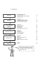
You will find this breakdown of the TwoHour Primer in the footer of each page.
The chapter you are currently in is highlighted in each case.
71
Preface
Dear S7-200 user,
Efficiency in the use of micro controllers depends primarily on how quickly and safely
you can learn to use a controller. We created the 1-and 2-hour primers so that even
beginners can learn to handle the S7-200 quickly and easily.
Building on the 1-hour primer, this 2-hour primer will familiarize you in a short time with
the principle of operation of the S7-200 controller. Using a few example tasks, the primer
shows you how the controller operates and how it can be used effectively for simple
tasks.
After working through the 2-hour primer, you will find it easy to solve typical controller
tasks on your own.
Enjoy reading your primer!
You can load the examples mentioned above from the enclosed diskette.
The S7-200 team wishes
you every success!
Revision
Latching
Pulse-Operated Switch
Off-Delay
Timer
Sequencer
Appendix
1
2
Revision
Latching
Pulse-Operated Switch
Off-Delay
Timer
Sequencer
Appendix
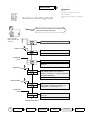
Chapter
Chapter header
- New, current
Chapter
logo
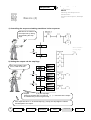
Primer symbols
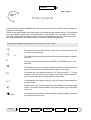
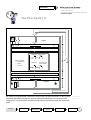
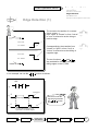
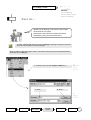
Certain symbols and text highlights are used frequently in the 2-hour primer. Their meanings are
explained on this page.
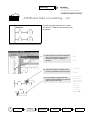
Check out the page header first! Each page has an identical page header design. The blue heading in large letters indicates the current sub-header of the chapter. The area "New" in the righthand side of the header shows the contents of the preceding pages with the contents of the current page highlighted in blue followed by the contents of the following page(s).
Text on a gray background prompts you to some action such as an input.
8
8
This symbol shows you that the left mouse key must be clicked once for
an action (e.g. mark field).
2x
©
Ë
F2
$
This symbol shows you that the left mouse key must be double-clicked for
an action.
Here you are prompted to press the ENTER (or RETURN) key on your
keyboard.
This indicates that you can select list points provided onscreen using the
mouse or optionally the keyboard (function keys, arrow keys).
This means you must press function key "F2" (function keys F1 ... F12 are
available). You will discover that, despite user-friendly mouse operation,
you can work faster with the keyboard in certain cases.
In combination with a page reference, you will find here further details on
a specific topic.
?
At these points, you will be requested to make entries in text fields on the
screen, or you will be reminded that in your own projects you should make
notes here.
Í Menu
A menu point on the screen is activated step-by-step (heading, sub-heading) with the left mouse key.
Revision
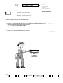
Latching
Pulse-Operated Switch
Off-Delay
Timer
Sequencer
Appendix
3
4
Revision
Latching
Pulse-Operated Switch
Off-Delay
Timer
Sequencer
Appendix
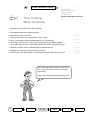
Revision
What you know already...
-
A Few Words of Revision
Here are the Bits
Current Flow in the Ladder Diagram
The PLC Cycle
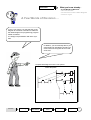
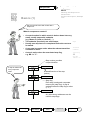
A Few Words of Revision ...
In the 1-hour primer, you saw that the circuit
diagram for contactor controllers is related to
the ladder diagram for programming programmable controllers.
It is simply a representation with other symbols.
In addition, you were already able to program small logic operations yourself. You
even learned to recognize timers in that
short time.
Compare with Page 24 in the 1-hour primer
Power rail phase
Revision
Latching
Pulse-Operated Switch
Off-Delay
Timer
Sequencer
Appendix
5
Revision
What you know already...
-
A Few Words of Revision
Here are the Bits
Current Flow in the Ladder Diagram
The PLC Cycle
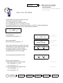
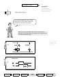
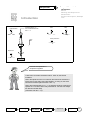
Here are the Bits
The smallest unit to be processed is the bit!
The bit can assume two states:
1) "1" meaning "bit set" or state is "true",
2) "0" meaning "bit not set " or state is "untrue",
In a method familiar to you, the two binary states "1" and "0" can be represented as
electrical circuits, that is, they can be represented by switches.
A closed switch:
Current flows so bit state = "1"
"1" ="true" =
Current flows
and an open switch:
No current flows so bit state = "0".
"0" = "untrue" =
No current
flows
From here it requires only a short step to the
representation of logic operations as circuits,
e.g. series connection of two contacts.
The AND operation of inputs I0.0 and I0.1
is represented as shown on the right.
AND operation
This is represented as follows in LAD:
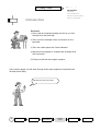
Finally, a small convention.
The following applies for positive logic:
24V = high-level = "1" und
0V = low-level = "0".
The following applies for negative logic:
0V = low-levgel = "1"
24V = high-level = "0".
6
Revision
Latching
positive logic
negative logic
Pulse-Operated Switch
Off-Delay
Timer
Sequencer
Appendix
Revision
What you know already...
-
A Few Words of Revision
Here are the Bits
Current Flow in the Ladder Diagram
The PLC Cycle
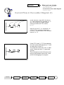
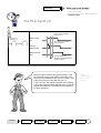
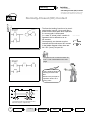
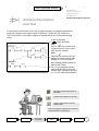
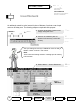
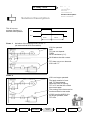
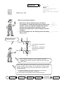
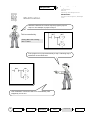
Current Flow in the Ladder Diagram (1)
In this example, output Q0.3 is active or
"1", if the contact at I0.1 is closed, i.e. "1"
(24 V DC at input I0.1) AND simultaneously, the timer bit T37 is active,
i.e. "1".
Input I0.1 is now "1", i.e. contact I0.1 is
closed. T37 is not active in the figure,
i.e. it is "0". For this reason, Q0.3 remains
inactive, i.e. "0".
If timer T37 is also "1" (T37 has elapsed),
the result of the AND operation is "1" and
so output Q0.3 is also "1".
The output bit is then also "true", in other
words, it takes the value "1" (gray background).
This corresponds to the LAD status view
that you have already used in the 1-hour
primer for debugging your program.
Revision
Latching
Pulse-Operated Switch
Off-Delay
Timer
Sequencer
Appendix
7
What you know already...
Revision
-
A Few Words of Revision
Here are the Bits
Current Flow in the Ladder Diagram
The PLC Cycle
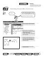
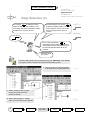
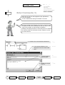
Current Flow in the Ladder Diagram (2)
(Using the Help Function)
Help displays
F1
1 Mark
element
2. F1
If you want to see again the on-line help
for a contact symbol or for other functions:
F1 On-line-help
Mark the contact:
•
in the Ladder Diagram (LAD) or
•
in the Function Block Diagram (FDB)
resp.
•
mark the contact in your STEP 7Micro/WIN ladder diagram
with a simple click of the mouse and then
press F1.
8
Revision
Latching
Pulse-Operated Switch
Off-Delay
Timer
Sequencer
Appendix
Revision
What you know already...
-
A Few Words of Revision
Here are the Bits
Current Flow in the Ladder Diagram
The PLC Cycle
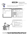
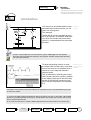
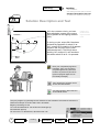
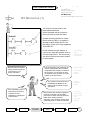
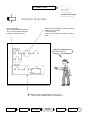
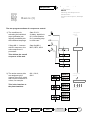
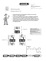
The PLC Cycle (1)
Inputs
PII = Process-image input table (input register)
Network 1
STEP-7 program
• Bit memories
•
Timers
•
Counters
•
.........
Motor on/off
Network 2
Direction reversal of rotation
PIQ = Process-image output table (output register)
Outputs
All SIMATIC programmable controllers usually work in a cyclical manner. In this cyclical
operation the switch statuses are read at the inputs and stored in the process input
image (PII). This information is subsequently used to feed and process the control program.
Revision
Latching
Pulse-Operated Switch
Off-Delay
Timer
Sequencer
Process Input
Image: PII
Appendix
9
Revision
What you know already...
-
A Few Words of Revision
Here are the Bits
Current Flow in the Ladder Diagram
The PLC Cycle
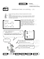
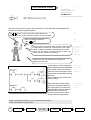
The PLC Cycle (2)
The outputs in the process-image output table (PIQ) are overwritten in accordance
with the switching logic in the program. The statuses in the PIQ are transferred to
the physical outputs in the final step. The cycle then begins again from the start.
Process-image
output table:
PIQ
A typical cycle takes between 3 and 10 ms. The
duration depends on the number and type of the
statements used.
The cycle consists of two main components:
1) Operating system time, typ. 1 ms; corresponding
to phase a and d Page 9.
2) Time for processing the commands;
corresponding to phases s‚ Page 9.
In addition, cycles are only processed when the
PLC is operating, in other words, it is in the "RUN"
operating state.
10
Revision
Latching
Pulse-Operated Switch
Off-Delay
Timer
Sequencer
Appendix
What you know already...
Revision
-
A Few Words of Revision
Here are the Bits
Current Flow in the Ladder Diagram
The PLC Cycle
The PLC Cycle (3)
Voltage at input changes
from 0 to 24 V
State of input
I0.0
Time until process image
(PII) has status “1”
Processimage of I0.0
State of output
Q0.0
Time for ladder logic
operations and modification of
the output status
Signal changes at inputs taking place during a cycle
are transferred to the input register in the next cycle.
There, the signal states for this cycle are "frozen". This
is the process-image input table PII (see a).
Outputs
modified only at
the end of the
next cycle
In the next cycle, the transferred states are combined
in accordance with the ladder diagram (see s) and the
outputs are updated in accordance with the results of
the logic operations.
Revision
Latching
Pulse-Operated Switch
Off-Delay
Timer
Sequencer
Appendix
11
Notes
Revision
12
Revision
Latching
Pulse-Operated Switch
Off-Delay
Timer
Sequencer
Appendix
Latching
Latching
-
Introduction
Normally-Closed (NC) Contact
Solution Description and Test
A Different Take on Latching
Introduction
You are sure to be familiar with the stan- Standard
dard latching function and here you will Locking
learn how to program it.
The example:
Output Q0.30 is to be activated as soon
as S1 at input I0.0 is operated. With latching, Q0.0 is to remain active until S2 at
input I0.1 is operated and thus interrupts
the latch.
In STEP 7-Micro/WIN open the first practice project "a:\d01.prj" from the diskette.
There are still a few elements missing in the program. Add the missing LAD elements
now as a short exercise.
Output Q0.0 as
To allow the latching function to work,
the output (Q0.0 in this case), must itself an input ensures
ensure, as soon as it is activated, that it latching
retains its "true" state and therefore
remains active.
This is achieved by switching the output
(Q0.0 in this case) as a contact in parallel
to the tripping input just in the same way
as with a conventional contactor circuit
(Q0.0 can be compared to our contactor
K1).
First add a contact Q0.0 at the point indicated as a parallel circuit to I0.0 (indicated by grey line)!
To enter the contact:
1) Click on the ladder diagram field with the left mouse button and click on the STEP 7-Micro/WIN
symbol for normally-open NO contact (F4). As indicated on the symbol, you can also use function
key F4 instead of the mouse.
2) To enter the vertical line, mark the ladder diagram field of I0.0 and click on the symbol (F7).
Revision
Latching
Pulse-Operated Switch
Off-Delay
Timer
Sequencer
Appendix
13
Latching
Latching
-
Introduction
Normally-Closed (NC) Contact
Solution Description and Test
A Different Take on Latching
Normally-Closed (NC) Contact
To allow the latching function to be terminated again, input I0.1 is to work like a
break in the current path when operated.
If a current path is interrupted
(i.e. state "0" exists) when a switch is
NC contact:
operated, this is referred to as an
NC contact.
Consequently, an element must be
inserted which works as an NC contact
in the ladder diagram when there are
24 V DC ("true") at input I0.1.
Complete an NC contact for switch S1
at I0.1. This is described on the next
page!
This is what the finished
latching function looks
like!
Below is the principle of
operation shown as a
timing chart.
Off priority
t = time till the results of logic operations are transferred to the outputs (= response time).
14
Revision
Latching
Pulse-Operated Switch
Off-Delay
Timer
Sequencer
Appendix
Latching
Latching
-
Introduction
Normally-Closed (NC) Contact
Solution Description and Test
A Different Take on Latching
Normally-Closed (NC) Contact (2)
I0.1
An NC contact interrupts the "current
flow" in the ladder diagram when the
input or output assigned to it is "true".
Insert the NC contact as follows:
1. Click the mouse to mark the position
that is to be replaced with an NC contact.
8 Mark
2. Select the NC contact with the
mouse from one of the two available
ladder diagram symbol bars
in STEP 7-Micro/WIN.
The NC contact is then positioned in
the marked field.
3. Finally, the desired element (I0.1 in
this case) must be assigned to the
NC contact. This is done with an
input in the already activated and
marked text field.
4. Always terminate text field inputs
by pressing Enter
Revision
Latching
Pulse-Operated Switch
Off-Delay
Timer
Sequencer
?
Assign
© Enter
Appendix
15
Latching
Latching
-
Introduction
Normally-Closed (NC) Contact
Solution Description and Test
A Different Take on Latching
Solution Description and Test
As in the contactor circuit, you have
also switched a contact of the output
(Q0.0) parallel to the tripping element
(I0.0).
Network 1
Output Q0.0
parallel to the
input maintains
itself
If, during a cycle, output Q0.0 has been
activated by operation of switch S1 at
I0.0, contact Q0.0 parallel to I0.0 appears
closed in the very next cycle (a few
milliseconds later). This brings about
latching. NC contact I0.1 can terminate
this when switch S2 at I0.1 is operated.
Save your completed program to
hard disk. Then you can load it
complete again at any time and
continue to process it (we will require the program again for our
OFF Delay example).
S
Then transfer the program to the
PLC to test the function.
For test purposes, switch the PLC
to the "RUN" mode.
Test your program by operating the two switches on the simulator connected at I0.0 and I0.1.
Observe the lamps on the S7-200 or the LAD status!
Begin by switching on I0.0.
I0.1 must be switched off. The LED at I0.0 must light up.
Q0.0 will then light up.
As soon as I0.1 is switched on, Q0.0 becomes ="0".
16
Revision
Latching
Pulse-Operated Switch
Off-Delay
Timer
Sequencer
Appendix
Latching
Latching
-
Introduction
Normally-Closed Contact
Solution Description and Test
A Different Take on Latching
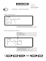
A Different Take on Latching ... (1)
In PLC technology, latching is often also implemented in another
variant:
Instead of feeding back the output - as in the previous example - here the
functions "Set" and "Reset" are simply used instead. Have a look first at
the ladder diagram below.
Because of the "Set" operation - (S), a
switching pulse at I0.0 has the effect
that Q0.0 is activated in a steady state.
In contrast, because of the "Reset"
operation - (R), a switching pulse at I0.1
has the effect that Q0.0 is deactivated
again.
-(S)
Set
-(R)
Reset
The "coils" - (S) Set Q0.0 to "1"
- (R) Reset Q0.0 to "0"
are used frequently in PLC technology to switch
briefly activated outputs or bit memories on or off with
steady state by means of a series-connected contact.
-( S ) Õ
-( R ) Õ
1
Steady-state
setting of value
with (S)
Resetting with
(R)
A "set" output or memory bit remains "set"
until it is reset by the
- (R) statement (becomes "untrue").
0
If the set coil and the associated reset coil of
an output both have signal "1", the last operation in the program takes priority.
Revision
Latching
Pulse-Operated Switch
Off-Delay
Timer
Sequencer
Last operation
in cycle has
priority
Appendix
17
Latching
Latching
-
Introduction
Normally-Closed Contact
Solution Description and Test
A Different Take on Latching
A Different Take on Latching ... (2)
You have already learned how to enter
I0.0 and I0.1. Enter the set and reset coil
as follows:
1. After marking the desired LAD field,
select "Coils" with a single mouse
click from the list for operation
families.
2. Then select "Set" (or "Reset") from
the list of operations that then opens.
3. In the already activated text field,
enter the output address you want to
affect, Q0.0 in this case.
8
Mark
Ë -(S)? Address
© Enter
Set (S) or reset
(R) up to 255
outputs, timers
or bit memories
with one
instruction
? Number
(1...255)
© EnterÌ
18
Revision
Latching
Pulse-Operated Switch
Off-Delay
Timer
Sequencer
Appendix
Latching
Latching
-
Introduction
Normally-Closed Contact
Solution Description and Test
A Different Take on Latching
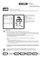
Safety Aspects
Shutdown if Wirebreak at Connection to S3
Switch with NC contact that
supplies the signal "0" when
operated.
In LAD, this signal is
reversed by the NC contact
I0.1
This means that if you operate the switch S3, Q0.0 is
reset.
!
Safety notes
• In the above example, an NC switch S3 was used for resetting.
When I0.0 is operated, output Q0.0 is set with steady state. If there are +24 V at I0.1, the
"NC contact" supplies the state "0" in LAD. Output Q0.0 is not reset. The LAD "power flow"
is interrupted and the coil for resetting is deactivated.
If there is no signal (0V) at I0.1 (S3 is open), the NC contact of I0.1 in LAD
= "1" and the output is reset.
When an NC switch is used at I0.1, the latching output Q0.0 is reset (switched off
again):
- if switch S3 is operated (I0.1 = "0") or
- if there is a break in the connecting cable between I0.1 and the NC switch. Even in the
event of wirebreak, it is guaranteed that a plant component operated in a steady state,
e.g. a motor, is switched off.
• The operation "Reset Q0.0" has been entered after the operation 'Set Q0.0' because this
means that in the event of both switches being operated simultaneously, clearing the latch
takes priority.
In STEP 7-Micro/WIN, open the exercise example "a:\d02.prj" from diskette and test the
functions!
Revision
Latching
Pulse-Operated Switch
Off-Delay
Timer
Sequencer
Appendix
19
Notes
Latching
20
Revision
Latching
Pulse-Operated Switch
Off-Delay
Timer
Sequencer
Appendix
Pulse-Operated Switch
Pulse-Operated Switch
-
Introduction
Solution Overview
Edge Detection
Bit Memories
Solution Description and Test
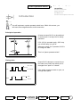
Introduction
You will implement a pulse-operated switch here. Within this context, you
will learn about edge detection and bit memories.
Principle of operation
A lamp at output Q0.5 is to be switched
on as soon as S1 at input I0.0 is briefly
operated.
If S1 (I0.0) is operated again, Q0.5 drop
out and the lamp is to go off.
Whenever switch S1 is operated, Q0.5 is
to change its state.
This is a "pulse-operated switch".
Timing chart
24 V “true”
I0.0
0 V “untrue”
Output Q0.5 is always to reverse its current state once when the switch at I0.0
changes from "open" to "closed".
If the switch remains closed or open, no
change takes place.
“true”
Q0.5
Revision
“untrue”
Latching
Pulse-Operated Switch
Off-Delay
Timer
Sequencer
Appendix
21
Pulse-Operated Switch
Pulse-Operated Switch
-
Introduction
Solution Overview
Edge Detection
Bit Memories
Solution Description and Test
Solution Overview
Before showing you the step-by-step solution of the task, we will show you the
finished solution in order to provide you with an overview.
Detect whether a change of state
from "0" to "1" (= positive edge) has
taken place at I0.0.
If output Q0.5 is "0", bit memory
M0.0 is set, this "flags" that Q0.5 in
Network 2 is to become "1".
"Reversing"
the state
old
new
state state
Assign the state of M0.0 to output
Q0.5.
22
Revision
Latching
If output Q0.5 is "1", bit memory
M0.0 is reset, this "flags" that Q0.5
in Network 2 is to become "0".
Pulse-Operated Switch
Off-Delay
Timer
Sequencer
Appendix
Pulse-Operated Switch
Pulse-Operated Switch
-
Introduction
Solution Overview
Edge Detection
Bit Memories
Solution Description and Test
Edge Detection (1)
The moment of transition of a contact
P
(input, output ...)
Detect rising
from "open" to "closed" or from "untrue" edge
to "true" is referred to as the rising or
positive edge.
24 V “true”
N
0 V “untrue”
Correspondingly, the transition from
"closed" to "open" or from "true" to
"untrue" is referred to as the falling or
negative edge.
Detect falling
edge
24 V “true”
0 V “untrue”
The two functions P
and N
are provided for detecting rising and
falling edges on the S7-200.
In our example, we use the
P
function as follows:
I0.0
P
a
s
Input signal
a
“1”
“0”
positive edge
positive edge
“1”
And this is what the
signal that generates
the
function
P
looks like.
s
“0”
Revision
For one cycle we get a"1" or a
signal flow in the ladder diagram.
Latching
Pulse-Operated Switch
Off-Delay
Timer
Sequencer
Appendix
23
Pulse-Operated Switch
Pulse-operated switch
-
Introduction
Solution Overview
Edge Detection
Bit Memories
Solution Description and Test
Edge Detection (2)
The contact P for detecting rising
edges is closed for the duration of one
cycle when the series connected contact
changes from "untrue" to "true"
Correspondingly, the contact N
for detecting falling edges is closed
for the duration of one cycle in the
event of changes from "true" to
"untrue".
P
N
In our "Two-way Switch", P
is therefore used to pass on a signal to
the subsequent logic operations only at
the moment that the button at I0.0 is
pressed.
And this is how
you enter it ...
In STEP 7-Micro/WIN, open the exercise project "a:\d03.mwp" from diskette.
This project is also incomplete and will be finished step by step.
1. Use the mouse to mark the position
to be replaced by an edge detection.
8 mark
2. Select ”Contacts” with a single
mouse click from the list for
operation families.
Ë edge
3. Select ”Rising edge” or ”Falling
edge” from the list that then appears.
24
Revision
Latching
8 mark
Pulse Operated Switch
Off-Delay
Timer
Sequencer
Appendix
Pulse-Operated Switch
Pulse-operated switch
-
Introduction
Solution Overview
Edge Detection
Bit Memories
Solution Description and Test
Bit Memories (1)
You require bit memories for the
pulse-operated switch.
A brief example will serve here to
show you how to work with them.
Instead of being used as an output,
the bit memory “M0.0“ is used as a
storage location within the PLC for
the interim result of the logic operation
“I0.0 AND I0.1“.
Bit memories are used for
storing interim results, as
in the memory of a
pocket calculator.
In this network, the bit memory is
used as an “input NO contact“ and so
controls output Q0.3. The bit memory
can still be used at any other location
in the program.
Can be used as
often as
required as NC
or NO contact
In PLC technology, bit memories are
used as outputs and have an effect
comparable with auxiliary contactors.
A bit memory can be used as often
as required at any location as an NC
contact or an NO contact.
Used as outputs
The contents of bit memories is
immediately available (in the
same cycle) for follow-on logic
operations.
If the operating power is
interrupted, bit memory
contents are lost.
Bit memories are used if the (interim)
result of a network is to be further
processed in other networks (like subtotals when adding numbers
manually). They are also used to store
evaluated follow-on states temporarily.
“Retentivity“ is designed
to prevent this.
Revision
Latching
Pulse Operated Switch
Off-Delay
Timer
Sequencer
Same effect as
auxiliary
contactors
Contents
immediately
updated
Can be overwritten several
times with -(S)
or (R)
Assign only
once with
-( )-
Appendix
25
Pulse-Operated Switch
Pulse-operated switch
-
Introduction
Solution Overview
Edge Detection
Bit Memories
Solution Description and Test
Bit Memories (2)
Now that you know the function of bit memories, you will be able to understand the
solution of the pulse-operated switch.
-(S)
Set
The P function enables signal flow (edge detection) in
Network 1 for one cycle each time the button at I0.0 is pressed.
-(R)
Reset
Q0.5 is to change its state at
each P edge
We do not write the reversed state (follow-on state) direct
to output Q0.5, because the output just set in the “upper“
branch, would be immediately reset again in the “lower“
branch. For this reason, we write the follow-on state to bit
memory M0.0 (= prevents overwriting).
Store follow-on
state in bit
memory as
protection
against
overwriting
In Network 2, the “set“ state of the bit memory is
assigned to the output.
At this point, a coil for setting bit M0.0 is set if
memory M0.0 must be positioned. Q0.5 was not
The number under the coil indi- active
cates how many elements are to ("untrue“)
be set from the specified starting
address.
Here: Setting of one bit from bit
memory M0.0.
Since the lower branch implements the reversed function of
the upper branch, the bit of bit
memory M0.0 must be reset, or
switched off, if this branch
“carries current“ as the result
of the button being pressed.
M0.0 is reset, if
Q0.5 was active
(„true“)
Finally, complete the example in your current exercise project in
STEP 7-Micro/WIN as shown above.
26
Revision
Latching
Pulse Operated Switch
Off-Delay
Timer
Sequencer
Appendix
Pulse-Operated Switch
Pulse-operated switch
-
Introduction
Solution Overview
Edge Detection
Bit Memories
Solution Description and Test
Solution Description
and Test
To summarize, the function of our now complete program is explained again below
using the example of the upper branch of Network 1 (ends with (S), switch on):
The "current flow" in the ladder diagram is represented at I0.0 in the positive edge
cycle!
If I0.0 is operated
( P edge detection)
and
“1”
Q0.5 is “0“ in the current cycle
(upper branch is true on scanning with NC contact)
then...
flag follow-on state of Q0.5 by
“1”
setting bit memory M0.0: -(S)
Setting of one bit from M0.0
M0.0 already has the follow-on
state of Q0.5 here.
Q0.5 is not assigned the new
state until the end ot the cycle
and so does not appear as “true“
or “1“ in the LAD representation.
Save the completed program to
hard disk.
Transfer the program to the PLC.
To test, switch the PLC to the
"RUN" mode.
Test your program: Operate the switch at
I0.0 and observe output Q0.5.
Revision
Latching
Pulse Operated Switch
Off-Delay
Timer
Sequencer
Appendix
27
Pulse-Operated Switch
Pulse-operated switch
-
Introduction
Solution Overview
Edge Detection
Bit Memories
Solution Description and Test
Time to Show
What You Know
... because you’ve made some real progress!
✔ Read and answer the questions below.
✔ What is the cycle of a PLC?
what are the three main components of the “cycle“?
See Page 9
✔ How is a latching function implemented in PLC technology?
See Page 13
✔ Normally-closed contact: How is this represented in the ladder diagram,
what effect does it have, which safety measures can be achieved using it?
See Page 14
✔ What is an edge, how is it detected and to what purpose?
See Page 23
✔ What are bit memories, what are they used for?
See Page 25
✔ How are the "Set" and "Reset" coils entered and what effect do they have?
See Page 26
You’re sure to know the answers to these questions, even if you have to look up the relevant
pages again.
But by now everything will have fallen into place!
28
Revision
Latching
Pulse Operated Switch
Off-Delay
Timer
Sequencer
Appendix
Off-Delay Timer
Off-delay timer
-
Introduction
Save As ...
Insert Network
Solution Description
Enter Comments
Introduction
You are already familiar with the On-delay
timer from the 1-Hour Primer. We will now
implement an Off-delay timer together.
When S1 (I0.0) is operated, a fan motor at output Q0.0 is
activated. If S1 (I0.0) is switched off, the fan is to continue to run
for 3 seconds and then stop.
If S1 is switched
off, the fan is to
continue to run
for 3 seconds
Timing chart
Revision
Latching
Pulse-Operated Switch
Off-Delay
Timer
Sequencer
Appendix
29
Off-Delay Timer
Off-delay timer
-
Introduction
Save As ...
Insert Network
Solution Description
Enter Comments
Introduction
Procedure
1) First, load the complete latching circuit from our first
example from the hard disk.
2) Then, save the example under a new name on the
hard disk.
3) Then we create space with "Insert Network"
4) We then work together to complete the off-delay timer
with comments.
5) Finally, we will test the program together.
In the coming pages, we will work through all the steps together to implement the
off-delay timer safely.
We wish you every success.
30
Revision
Latching
Pulse-Operated Switch
Off-Delay
Timer
Sequencer
Appendix
Off-Delay Timer
Off-delay timer
-
Introduction
Save As ...
Insert Network
Solution Description
Enter Comments
Save As ...
We will use the latching circuit from the first chapter
as the basis for our project.
Duplicate the entire project by loading it and then
immediately saving it under another name.
In STEP 7-Micro/WIN, load your project "d01.prj" (latching circuit) from the hard
disk. You stored it there in the first chapter.
Now you want to save the project under a new name. Save the project as described below
under the name "d04.prj".
1. Call the menu function "Project >Save As ..."
2. "d04"
"d04.mwp"
2.
Í Menu:
Project,
Save As...
3. "Save"
?
d04.prj
8 Save
Revision
Latching
Pulse-Operated Switch
Off-Delay
Timer
Sequencer
Appendix
31
Off-Delay Timer
Off-delay timer
-
Introduction
Save As ...
Insert Network
Solution Description
Enter Comments
Insert Network
An additional network is to be inserted in place of Network 2 so that we can implement the off-delay timer. The following steps are required for this purpose:
1. Activate the title field of Network 2 by
simply clicking the mouse.
2. Insert a new network in place of
Network 2 (function key F10 has the
same function as a click on the button
shown).
8 mark
Ë
Network button
in the toolbar
(F10)
You have created space for the new Network 2 that you will use
for implementing the off-delay timer. The contents of the original
Network 2 have "moved on" one network.
Note:
There is also the following method of creating space for entering
LAD elements:
3. Select "Insert ..." from the Edit menu.
Í Menu:
Edit,
Insert...
4. Select
“Network”
32
Revision
Latching
Pulse-Operated Switch
Off-Delay
Timer
Sequencer
Appendix
Off-Delay Timer
Off-delay timer
-
Introduction
Save As ...
Insert Network
Solution Description
Enter Comments
Solution Overview
I0.0 activates Q0.0
Q0.0 maintains its state (latches)
since it is also switched simultaneously in parallel with I0.0.
When T37 has elapsed, the latch function is
broken via this contact.
The motor stops.
If T37 has not elapsed, the latch remains in
force.
This is how the finished
program appears..
When Q0.0 is operated and I0.0 is "0" again
(S1 no longer operated), timer T37 starts to run.
Revision
Latching
Pulse-Operated Switch
Off-Delay
Timer
Sequencer
Appendix
33
Off-Delay Timer
Off-delay timer
-
Introduction
Save As ...
Insert Network
Solution Description
Enter Comments
Solution - Enter Program
Network 1 must look like this:
Overwrite I0.1 of the latching circuit with T37.
Enter the following program in Network 2:
Enter T37 with
F2 Timers/Counters and
F3 Timer as on delay
T37 has a timebase of 100 ms (see also
“1-Hour Primer”, Page 36)
The time value is therefore 30 * 100 ms = 3 s.
34
Revision
Latching
Pulse-Operated Switch
Off-Delay
Timer
Sequencer
Appendix
Off-Delay Timer
Off-delay timer
-
Introduction
Save As ...
Insert Network
Solution Description
Enter Comments
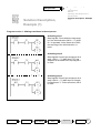
Solution Description
This is how our
program functions. It
has two active phases.
I0.0
Q0.0
Phase 2
Phase 1
Phase 1:
Activation of the latching circuit, I0.0 is "1"
(we assume that Q0.0 is not active).
If I0.0 is operated
AND
T37 has not elapsed
THEN
Q0.0 is activated (="1").
Q0.0 latches via this contact.
T37 does not yet run because
I0.0 is still "1".
Phase 2:
I0.0 is no longer operated.
The latch remains in force
until T37 has elapsed.
While the timer is running,
T37 is "0" and the NC contact
lets current pass.
The running of the timer can be
monitored here in test mode.
If Q0.0 is active AND I0.0 is
no longer operated, timer
T37 runs.
Revision
Latching
Pulse-Operated Switch
Off-Delay
Timer
Sequencer
Appendix
35
Off-Delay Timer
Off-delay timer
-
Introduction
Save As ...
Insert Network
Solution Description
Enter Comments
Enter Comments (1)
Save and try out your new program! If you operate I0.0,
Q0.0 is activated.
If I0.0 is switched off, Q0.0 goes off after 3 seconds.
Well done! Maybe it has already occurred to you that it would
be helpful for later work (modifications and such like) to store
notes in the program on the principle of operation.
Naturally, we thought of that too. That is why there is a method
for entering a title and comments for each network. I’ll show
you how to do this.
1. Double-click on the title field of Network 2.
2. The Comment Editor is now
displayed. Enter the network title
here ...
3. ... and the network
comments here.
4. Confirm your inputs
with OK.
36
Revision
Latching
Pulse-Operated Switch
Off-Delay
Timer
Sequencer
8 2x
? Title
?
Comments
8 OK
Appendix
Off-Delay Timer
Off-delay timer
-
Introduction
Save As ...
Insert Network
Solution Description
Enter Comments
Enter Comments (2)
Start 3s off-delay timer
After adding the comments, only
the network title is visible on
screen.
The comments can be made
visible again later by reactivating the Comment Editor.
If you want your comments to be included in
the printout, you can do so with the menu ,
function "File/Print/Print Options".
Í Menu:
Project,
Page Setup
ã Print
Network
Comments
8 OK
Revision
Latching
Pulse-Operated Switch
Off-Delay
Timer
Sequencer
Appendix
37
Off-Delay Timer
Off-delay timer
-
Introduction
Save As ...
Insert Network
Solution Description
Enter Comments
Time To Show
What You Know
Please read and answer the questions below.
✔ How do you implement an off-delay timer? Draw the ladder diagram for two
possible solutions. Once with the normal coil
—( )— and once with (S) and (R).
See Page 29
✔ How do you save a project?
See Page 31
✔ How do you determine the value of a timer?
See Page 36 in
“1-Hour Primer”
See Page 36
✔ What comments can be made on networks?
Diploma
38
Revision
Latching
Pulse-Operated Switch
Off-Delay
Timer
Sequencer
Appendix
Sequencer
Sequential control
-
Introduction
Initial situation
Introduction
Basics
Working with Sequencers
Modification
Solution Description, Example
Test
Start
Clockwise Q0.0 = "1"
Anti-clockwise Q0.0 and
Q0.1 = "1"
Stop
Motor protection
Feed
Q0.2
Depth limit
Now we will implement a
sequencer together.
A drill motor is started clockwise with S1. After 3s, the feed is
activated.
When the depth limit at I0.3 is reached, the feed is de-activated. A
spring returns the drill to the initial situation. In doing so, the drive
turns anti-clockwise (Q0.0 and Q0.1 are "1").
When the initial situation I0.4 = "1" is reached, the drive continues to
operate for 1s until the drill is fully switched off. The drill can always
be switched off with Stop
(activation with I0.0 = "0").
Revision
Latching
Pulse-Operated Switch
Off-Delay
Timer
Sequencer
Appendix
39
Sequencer
Sequential control
Solution Starting Point
-
Introduction
Basics
Working with Sequencers
Modification
Solution Description, Example
Test
This is what the solution for the sequencer
of the drill example looks like.
First cycle SM0.1
Motor protection I0.5
Delete step flags M0.1 to M0.5.
Stop I0.0
Start S1
Drill spindle rotates clockwise Q0.0="1”
Power up time (T37) of 3s is started.
3s elapsed
(T37)
Feed on Q0.2="1"
Drill spindle continues to rotate clockwise
Q0.0="1".
Depth limit
When depth limit is reached,
drill spindle rotates anti-clockwise
Q0.0="1" and Q0.1="1" (reverse direction
of rotation with Q0.1).
Feed is switched off Q0.2="0".
Initial situation
When initial situation is reached I0.4="1",
drill spindle continues to rotate for 1s
(T38), Q0.0 = "1" and Q0.1 = "1".
1s elapsed
(T38)
Drill spindle stops Q0.0="0" and
Q0.1="0".
Set step 0.
Continue with step 0
40
Revision
Latching
Pulse-Operated Switch
Off-Delay
Timer
Sequencer
Appendix
Sequencer
Sequential control
-
Basics (1)
Introduction
Basics
Working with Sequencers
Modification
Solution Description, Example
Test
We will now solve the drill control with a
sequencer.
What is a sequencer control?
• A control method in which a task is broken down into very
small, usually sequential, subtasks
(e.g. Motor on, feed on, feed off, ...).
• The subtasks (functions) are called steps.
• Usually one step has to be completed before the next one
is started.
• A new step becomes active when the relevant transition
condition is active.
• A step is active when the associated step flag,
e.g. M0.1 = "1".
Steps
Transition
condition
Active step
Í
step flag
MX.Y = "1"
Step number provides
unique identifier
Motor on
A step is defined for
every important
state.
Subtask/function of the step
(action)
Feed on
Step flag
Each step is assigned a separate
memory bit (step flag). A step is
activated when the step flag is active
(= "1").
Feed off
Any bit memory addresses can be
used for step flags.
Revision
Latching
Pulse-Operated Switch
Off-Delay
Timer
Sequencer
Appendix
41
Sequencer
Sequential control
-
Basics (2)
Introduction
Basics
Working with Sequencers
Modification
Solution Description, Example
Test
What is a transition condition?
• Each step is started (activated) by a condition).
The condition is usually derived from the states of the
machine. These can include actuated limit switches,
operator keys, temperatures reached or timers.
• An active preceding step is almost always part of the
condition.
• If a new step flag is set, the step flag of the preceding
step is reset.
Transition
condition
activates step
flag
Active step flag
"1"
Always activate only
one step at a time.
Depth limit
The condition for activating
step 4 is:
I0.4 must be "1" AND M0.3
(the step flag from step 3)
must be "1".
Initial situation
If this condition is fulfilled, e.g. timer elapsed, limit switch
actuated, a new step is activated. Usually, another active step
is then reset.
When making transitions in the sequencer, we are not yet concerned
with the activation of the outputs. This is dealt with in a later program
section. This means that a control with sequencers consists of two
program sections:
1) The actual transitions from step to step when the necessary
conditions are fulfilled (transition conditions).
2) The activation of the outputs (control valves and drives).
42
Revision
Latching
Pulse-Operated Switch
Off-Delay
Timer
Sequencer
Appendix
Sequencer
Sequential control
-
Basics (3)
Introduction
Basics
Working with Sequencers
Modification
Solution Description, Example
Test
The two program sections of a sequencer control:
1) The conditions for
activating the individual
steps (subtasks) are
logically combined with
the individual step flags.
If flags M0.1... become
active in sequence, the
entire sequencer is
processed.
Start S1 I0.1,
3s delay, depth limit
I0.3, initial situation
I0.4, preceding step
in each case.
1. Program
section
Start
Step flag M0.1,
M0.2, M0.3, M0.4
Sequencer
This defines the overall
sequence of the task.
2) The active memory bits
are assigned to the
outputs of the PLC which
then control contactors or
valves, for example.
Q0.1, Q0.2,
Q0.0
2. Program
section
Command output
This is the interface to
the plant /machine.
Revision
Latching
e.g. motors,
valves
Pulse-Operated Switch
Off-Delay
Timer
Sequencer
Appendix
43
Sequencer
Sequential control
-
Basics (4)
Introduction
Basics
Working with Sequencers
Modification
Solution Description, Example
Test
1) Controlling the sequencer/making transitions in the sequencer
Transitions are made in
the sequencer by sitting
and resetting the step
flags.
M0.2 and M0.3
are step flags
here
2) Setting the outputs via the step flags
If an output inside a step
ist "0", it will not be set.
Outputs are set only by the step flags.
Assigning outputs with a normal coil —( )— ensures that the output
is activated only in the one given step.
If an output has to be "1" in several steps (e.g. Q0.0), the step flags are "ORed"
and assigned to the output.
44
Revision
Latching
Pulse-Operated Switch
Off-Delay
Timer
Sequencer
Appendix
Sequencers
Sequential control
-
Working with
Sequencers (1)
Introduction
Basics
Working with Sequencers
Modification
Solution Description, Example
Test
• A separate memory bit (step flag) is assigned to each step.
This is "1" if the step is active.
• For the sake of clarity, only one step in a sequencer should be
active at any time. This means only one step flag should be "1".
• If the task is more complex, it is best to use a further sequencer.
• If two or more processes must be controlled simultaneously and
independently, separate sequencers are used. This is shown in
the diagram below.
Sequencer A
Sequencer B
Revision
If M0.3 ="1", the two
sequencers B and C start.
Memory bits M0.4 and M1.1
are set by M0.3.
M0.3 is then reset and
sequencers B and C continue
to run.
Sequencer C
Latching
Pulse-Operated Switch
Off-Delay
Timer
Sequencer
Appendix
45
Sequencer
Sequential control
-
Working with
Sequencers (2)
Introduction
Basics
Working with Sequencers
Modification
Solution Description, Example
Test
The transition condition is in practice also made up of several contacts.
Our example can be expanded in such a way that, for example, the start can only
take place if the drill is in the initial situation. The sequencer then looks like this at
this point:
Start
Initial
situation
46
Revision
Latching
Pulse-Operated Switch
Off-Delay
Timer
Sequencer
Appendix
Sequencer
Sequential control
-
Working with
Sequencers (3)
Introduction
Basics
Working with Sequencers
Modification
Solution Description, Example
Test
Advantages
• The control section of the sequencer and the setting of
the outputs are kept separate
- If an output is now to be active in step 7 in addition to step
2 and 3, the program need only be modified at one point.
previous
modified
M0.2
Q0.3
M0.2
Q0.3
M0.3
M0.3
M0.7
- Modifications to the control section of the sequencer do not
affect the setting of the outputs.
• The program is easy to test
- Each step can be traced easily on the programming device.
- If transitions do not function, it is easy to detect which
condition is missing.
• Machine
- If a machine ceases to operate, it is easy to detect the
missing transition condition from the mechanical position of
the machine and the active step flag.
• Fewer programming errors, faster startup
- Using sequencers forces you to structure your programs
which in turn minimizes programming errors.
Revision
Latching
Pulse-Operated Switch
Off-Delay
Timer
Sequencer
Appendix
47
Sequential control
Sequencer
-
Introduction
Basics
Working with Sequencers
Modification
Solution Description, Example
Test
Important Safety Points (1)
There should be not drives or valves active in the first step flag
(initial situation). In our example, this is step 0 or step flag M0.0.
When "STOP" is operated or a motor protector picks
up, the first step flag (M0.0 in our example) need
only be set for all drives to come to a stop. At the
same time, all other step flags must be reset.
M0.0 is set, M0.1 to M0.5 are reset
- in the first cycle after power
restore by SM0.1 or
- if I0.0="0" or
- if I0.5="0".
SM0.1 supplies
"1" for one
cycle in the first
cycle after
restarting
The program section shown in the example must be at the end of the "normal" transition conditions of the sequencer. This ensures that any necessary shutdown can
take place prior to activating the outputs.
48
Revision
Latching
Pulse-Operated Switch
Off-Delay
Timer
Sequencer
Appendix
Sequencer
Sequential control
-
Important Safety
Points (2)
Introduction
Basics
Working with Sequencers
Modification
Solution Description, Example
Test
Program section 1 – Making transitions in the sequencer:
a
Program section 1:
controlling the
sequencer and
making transitions
•
•
•
s
Program section 2:
Initialization
and Stop
Number of memory
bits to be reset
•
•
•
d
Program section 3:
Setting the outputs
•
•
•
Before assigning the first output d, the program section for activating the initial situation must be in place s. This ensures that activation of the initial situation has the
highest priority.
Revision
Latching
Pulse-Operated Switch
Off-Delay
Timer
Sequencer
Appendix
49
Sequencer
Sequential control
-
Modification
Introduction
Basics
Working with Sequencers
Modification
Solution Description, Example
Test
Network 6 determines in which step the program jumps to
step 5. In the example, it jumps in step 0.
This is controlled by:
Setting M0.0 and resetting
M0.1 to M0.5.
If the program is to jump automatically to step 1 following step 5,
Network 6 must look like this.
This modification causes the drill to run automatically until
stopped by I0.0 or I0.5.
50
Revision
Latching
Pulse-Operated Switch
Off-Delay
Timer
Sequencer
Appendix
Sequencer
Solution Description,
Example (1)
Sequential control
-
Introduction
Basics
Working with Sequencers
Modification
Solution Description, Example
Test
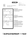
Program section 1 - Making transitions in the sequencer
Activating step 1
Step flag M0.1 is set when the sequencer
is in the initial situation (M0.0 = "1") AND
I0.1 is operated. At the same time, M0.0,
the step flag of the initial situation, is
reset.
Activating step 2
Step flag M0.2 is set if the sequencer is at
step 1 (M0.1 = "1") AND timer T37 has
elapsed. At the same time, step flag M0.1
is reset.
Activating step 3
Step flag M0.3 is set if the sequencer is at
step 2 (M0.2 = "1") AND input I0.3 depth
limit becomes "1". At the same time, M0.2
is reset.
Revision
Latching
Pulse-Operated Switch
Off-Delay
Timer
Sequencer
Appendix
51
Sequencer
Sequential control
Solution Description,
Example (2)
-
Introduction
Basics
Working with Sequencers
Modification
Solution Description, Example
Test
Activating step 4
Step flag M0.4 is set if the sequencer
is at step 3 (M0.3 ="1") AND input I0.4
(initial situation) becomes "1". At the
same time, M0.3 is reset.
Activating step 5
Step flag M0.5 is set if the sequencer
is at step 4 (M0.4 = "1") AND timer T38
has elapsed. At the same time, step flag
M0.4 is reset.
Activating step 0
If step flag M0.5 is active (overshoot
time T38 is finished), step 0 (initialization
step) is activated from the sequencer.
This step in Network 6 has been
included deliberately so that further conditions such as removal of the workpiece
could be scanned at this point before reactivation of step 0.
This condition would then have to be
switched in parallel to contact M0.5.
52
Revision
Latching
Pulse-Operated Switch
Off-Delay
Timer
Sequencer
Appendix
Sequencer
Solution Description,
Example (3)
Sequential control
-
Introduction
Basics
Working with Sequencers
Modification
Solution Description, Example
Test
Activating timer T37
If step 1 is active (M0.1 = "1"), timer T37
is started.
Activating timer T38
If step 4 is active (M0.4 = "1"), timer T38
is started.
Initialization of a sequencer
Step flag M0.0 is set
1) in the first cycle (SM0.1 is "1"
here for one cycle)
OR
2) if Stop is operated
(I0.0 = "0")
OR
3) if the motor protection has
picked up (I0.5 = "0").
At the same time, step flags
M0.1 to M0.5 are reset.
Revision
Latching
Pulse-Operated Switch
Off-Delay
Timer
Sequencer
Appendix
53
Sequencer
Sequential control
Solution Description,
Example (4)
-
Introduction
Basics
Working with Sequencers
Modification
Solution Description, Example
Test
Program section 2 - Setting the outputs
Activate output Q0.0
(drive clockwise)
Output Q0.0 is "1" in steps 1, 2, 3, 4,
i.e. if M0.1 or M0.2 or M0.3 or M0.4
are "1".
Activate output Q0.1
(direction reversal)
Output Q0.1 is "1" in steps 3 and 4,
i.e. if M0.3 or M0.4 are "1".
Activate output Q0.2
(feed on)
If memory bit M0.2 = "1" output Q0.2
will become "1".
54
Revision
Latching
Pulse-Operated Switch
Off-Delay
Timer
Sequencer
Appendix
Sequencer
Sequential control
-
Test
Introduction
Basics
Working with Sequencers
Modification
Solution Description, Example
Test
You can enter the program yourself or load the file "d05.prj" from the diskette.
Please note that the stop switch I0.0 and the motor protection I0.5 are "normallyclosed (NC) contacts". This has been implemented in this way for safety reasons.
A wirebreak between the switches and the PLC stops the machine!
I0.5 and I0.0 must be "1" for test purposes, that is, the input LEDs must light up.
Briefly operating I0.1 starts the drive. The feed Q0.2 switches on after 3 s. After
I0.3 is operated, the drive reverses its direction of rotation and the feed Q0.2 stops.
If the initial situation is reached (brief operation of I0.4), the drive stops after 1s.
I0.0 and I0.5 stop the drive in every phase.
Observe the program in test mode. You will see exactly which input is required in
each case for making the transitions in the sequencer.
Try it out !
Revision
Latching
Pulse-Operated Switch
Off-Delay
Timer
Sequencer
Appendix
55
Sequencer
56
Revision
Latching
Pulse-Operated Switch
Notes
Off-Delay
Timer
Sequencer
Appendix
Made it.
Now you can solve tasks yourself
using the S7-200. If you want to
implement complex contactor circuits,
you can find some useful tips in the
Appendix.
Revision
Latching
Pulse-Operated Switch
Off-Delay
Timer
Sequencer
Appendix
57
58
Revision
Latching
Pulse-Operated Switch
Off-Delay
Timer
Sequencer
Appendix
Fancy Some More?
You can find more examples in the "Samples" folder in your STEP 7-Micro/WIN
folder or the "Tips & Tricks" for the S7-200. You can obtain the "Tips & Tricks" from
your SIMATIC contact.
The S7-200 manuals contain further information. You can get comprehensive further training in an S7-200 course at your Siemens Training Center or from your
SIMATIC contact.
Unanswered questions
or technical problems:
The SIMATIC contacts
are glad to help.
Please get in touch with your SIMATIC contact who
supplied your Startup Package. He/she will be glad to help.
If your contact is unavailable, please call our SIMATIC Hotline,
Tel.: ++49 911/895-7000.
Revision
Latching
Pulse-Operated Switch
Off-Delay
Timer
Sequencer
Appendix
59
60
Revision
Latching
Pulse-Operated Switch
Off-Delay
Timer
Sequencer
Appendix
We have put together a few examples
below to make it easy for you to implement even complex "switching operations" in ladder logic.
Revision
Latching
Pulse-Operated Switch
Off-Delay
Timer
Sequencer
Appendix
61
62
Revision
Latching
Pulse-Operated Switch
Off-Delay
Timer
Sequencer
Appendix
Appendix
Tips
You will find a few valuable
tips on these pages.
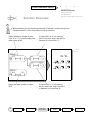
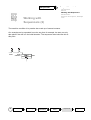
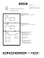
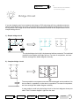
Bridge Circuit
If you are changing over from contactor technology to PLC technology will very probably encounter
switch combinations that cannot be converted directly into ladder diagram representation. Included
among these is the bridge circuit. Brief solutions are sketched here both for the simple and the more
complex bridge circuit.
1) Simple bridge circuit
a
b
c
d
E
F
The simple bridge circuit (left) is implemented with two networks. The individual
possible current paths are simply split up. For ease of comparison, we have
likewise arranged the ladder diagram vertically.
2) Complex bridge circuit
a
b
c
d
e
F
The two possible current paths have been converted again and recombined. On
the one hand, a,c parallel b, on the other b,c parallel a. For ease of comparison,
we have arranged the ladder diagram vertically.
In new projects, avoid using the bridge circuit in the circuit diagram where possible! Think "in ladder diagram" right from the start.
Revision
Latching
Pulse-Operated Switch
Off-Delay
Timer
Sequencer
Appendix
63
A1
Tips
Appendix
You will find a few valuable
tips on these pages.
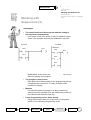
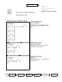
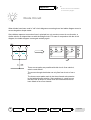
Diode Circuit
When diodes have been used in "old" circuit diagrams converting them into ladder diagram terms is
not an altogether simple matter.
Since diodes represent connection lines in principle but only conduct current in one direction, a
similar solution is adopted here as with the bridge circuit. For ease of comparison with the circuit
diagram, the ladder diagram is arranged vertically again.
Three current paths are possible with this circuit: Over switch d,
switch e and switch f.
The current through the diodes can only flow from b to d or from c
to e.
The three current paths result in the three framed sub-networks
in the ladder diagram solution. Since switches d, e and f are on
the same rail as output G, these three sub-networks have also
been linked to form one network.
64
A2
Revision
Latching
Pulse-Operated Switch
Off-Delay
Timer
Sequencer
Appendix
Appendix
Tips
You will find a few valuable
tips on these pages.
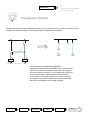
Changeover Switch
Changeover switches should likewise not cause you any problem when you are converting a circuit
diagram into a ladder diagram. This transformation is explained briefly below.
a
b
D
C
The current path is graphically highlighted.
Changeover switch b is then divided into a normally closed
(NC) contact that is switched in series with a and contributes to the effect at output C, or a normally open (NO) contact that takes effect in parallel with a and switches D.
In this way it is in principle possible to convert a changeover switch using an NC contact and an NO contact with
the same input address in the ladder diagram.
Revision
Latching
Pulse-Operated Switch
Off-Delay
Timer
Sequencer
Appendix
65
A3
Tips
Appendix
Notes.
Notes
66
A4
Revision
Latching
Pulse-Operated Switch
Off-Delay
Timer
Sequencer
Appendix
Appendix
Index
For reference, cross
references to manuals,
and abbreviations.
$
Index
A...I
This index contains the most important terms in programming the S7-200. You will find
brief explanations of the abbreviations used in the Primer as well as some cross references to the One Hour Primer.
The following symbol is used in the Index:
1h-& References to pages in the 1-Hour Primer
A
E
Edges: 21,22
END: Program end statement 31
Entering comments: 36 +
B
Basics of the sequencer: 39-42
Binary: Representation of numbers in bits
(two possible values, 0 or 1)
Bit memories: 25+
Bit: Binary digit: 6
Bridge circuit: A1
Byte: 8-bit wide value: 1h-& 48
F
G
H
HMI: Human-machine interface
C
Coil: Representation for an output element in
the ladder diagram (comparable with a
contactor): 17
CPU: Central Processing Unit, e.g. the S7-200
Current flow in the ladder diagram: 7
D
I
I: Input, e.g. I0.0
IB: Input byte (8 bits), e.g. IB0
Insert network: 32
Inserting elements: 1h-& 30
IW: Input word (16 bits), e.g. IW0
Data block: Variable memory of the S7-200,
values for use in the control program can
be stored here
DB1: Data block of the S7-200
Diode circuit: A2
DIV: Arithmetic division e.g. with text
displays, operator panels and touch panels
Revision
Latching
Pulse-Operated Switch
Off-Delay
Timer
Sequencer
Appendix
67
B1
Index
Appendix
For reference, cross
references to manuals
and abbreviations.
$
Index
K...S
K
R
Reset, Set: 16 +
RET: Return, end subroutine
Retentivity: 23
RUN: Position of the S7-200’s mode selector
switch for manual startup/restart of the
controller
L
Ladder diagram: 1h-& 25
Ladder status: 7, 1h-& 26
Latching function solution: 15 +
Latching: 13 +
S
M
MB: Memory byte (8 bits)
MD: Memory double-word (32 bits)
Mode selector switch: Switch on the S7-200
with three settings: STOP, TERM, RUN.
MW: Memory word (16 bits)
N
Normally-closed (NC) contact: 14, 15
Normally-open (NO) contact: 8
O
OB1: Organization block of the S7-200
Off-delay timer solution: 29 +
Off-delay timer: 29 ff.
On-delay timer: 1h-& 35
On-line Help: 8
Organization block:
contains the cyclically executed user
program of the controller
P
PIQ: Process-image output table: 10
PII: Process-image input table: 9
PLC: Programmable logic controller.
Process-image: A PLC program works on an
I/O image. At the start of the cycle, the
input image is read in and at the end of
the cycle the output image is transferred
to the actual outputs: 9 +
Pulse-operated switch solution: 21 +
Pulse-operated switch: 21 +
68
B2
Revision
Latching
Pulse-Operated Switch
Safety aspects: 19
Saving the program: 1h-& 41
SBR: Subroutine,
Semi-automatic controller: Controller that can
execute certain sequences autonomously
but depends on user inputs at other points.
Sequencer solution: 39 +
Sequencer: Usually self-contained sequence
of steps that is processed step-by-step in a
sequential control: 39 +
Sequential control: Control that derives steps
from events or makes transitions between
steps. These, in turn, activate prescribed
actions.
Set, reset: 17 +
SMB: Special memory byte (8 bits), e.g.
SMB28
SMB28: Potentiometer of the S7-200
SMD: Special memory double-word (32 bits)
SMW: Special memory word (16 bits)
Status in the ladder diagram: 1h-& 26
Status: Permits monitoring of a process on the
program level or in a special status table.
Useful for test and diagnostics.
Step flag: 41
STL: Statement list
STOP: Position of the S7-200’s mode selector
switch for manual stopping of the controller.
Off-Delay
Timer
Sequencer
Appendix
Appendix
Index
For reference, cross
references to manuals
and abbreviations.
$
Index T...Z
T
W
T37 (Timer): 29 +
TERM: Position of the S7-200’s mode
selector switch. Lets you influence the
controller from STEP 7-Micro/WIN
Timer
TON: S7-200 time switch, also called timer:
1h-& 36 f.
TONR: Latching on-delay timer
Training model: 1h-& 7
Transition condition: 40
True, untrue: 6
Timer
TON: S7-200 time switch, also called timer:
1h-& 36 f.
TONR: Latching on-delay timer
Word: A value represented by 2 bytes (16 bits).
Working with sequencers: 45 ff.
X
XOR: Exclusive OR, logic operation that
switches only in the case of different
states (antivalency) at the input
Z
Z0: Simple counter (CTU)
U
Untrue, true: 6
V
V: Variable bit, e.g. V0.0
VB: Variable byte, e.g. VB0
VD: Variable double-word, e.g. VD45
V memory: Data block in the S7-200
VW: Variable word, e.g. VW45
Revision
Latching
Pulse-Operated Switch
Off-Delay
Timer
Sequencer
Appendix
69
B3
To
Siemens AG
A&D AS MVM
Gleiwitzer Str. 555
Fax: +49 911 895-2786
90475 Nuernberg
Germany
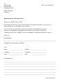
Response to the "Two-Hour Primer"
Dear user of the Micro PLC S7-200,
We created the Two-Hour Primer so that, building on the One-Hour Primer, you can learn to
use the Micro PLC S7-200 within a very short time.
We are sure that you will easily be able to solve typical control tasks with this primer.
However, if you do have any suggestions, it is important to us to hear your opinion.
Please send us this form, stating your name and address so that we can contact you directly.
Thank you
A&D AS MVM
_________________________________________________________________________________
Suggestions, Improvements, Feedback
From
Name
_____________________
Position
________________________
Company _____________________
Telephone ________________________
Street
Place
_____________________
________________________
My suggestions:
_________________________________________________________________________________
_________________________________________________________________________________
_________________________________________________________________________________
_________________________________________________________________________________
_________________________________________________________________________________
_________________________________________________________________________________
70
A&D AS MVM/012000
Appendix
Tips
Notes.
72