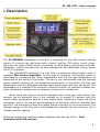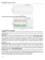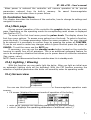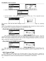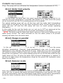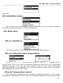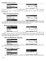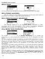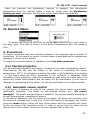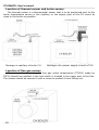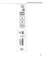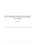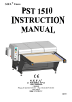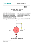
1
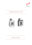
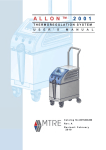
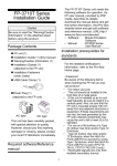
ST-850zPID –User's manual TECH Declaration of Conformity No. 54/2012 Hereby, we declare under sole responsibility that the ST-850 230V 50Hz thermoregulator manufactured by TECH, headquartered in Wieprz 1047A, 34-122 Wieprz, is compliant with the Regulation by the Ministry of Economy. (Journal of Laws Dz.U. 155 Item 1089) of July 21, 2007 implementing provisions of the Low Voltage Directive (LVD) 2006/95/EC of January 16, 2007. The ST-850 controller has been tested for electromagnetic compatibility (EMC) with optimal loads applied. For compliance assessment, harmonized standards were used: PN-EN 60730-2-9:2011, PN-EN 60730-1:2012 -2- ST- 850 z PID – User's manual ATTENTION! High voltage! Make sure the regulator is disconnected from the mains before working on the power supply (cable connections, device installation, etc.)! All connection works must only be carried out by qualified electricians. Before activating the controller, measure the motor resetting efficiency and inspect wire insulation. 3- ST- 850 z PID – User's manual I. Description The ST-850zPID temperature controller is designed for use with central heating boilers. It controls the following units: central heating (CH) water circuit pump, domestic hot water (DHW) pump, circulating or valve pump, mixing valve and fan. Optionally, control functions can be also provided for two additional mixing valves via ST-61 modules. The ST-850zPID controller is a unit with a continuous output signal using a modified PID control algorithm. In this type of controller the blowing power is calculated by measuring the boiler temperature and the flue gas temperature as measured at the outlet of the boiler. The fan is run continuously and the blowing power depends directly on the measured temperature of the boiler, the flue gas temperature and the difference between these parameters and their set-points. The advantages of a modified PID controller include the ability to maintain a stable setpoint temperature without any unnecessary overshoot or oscillations. When using this type of controller equipped with a flue gas outlet sensor fuel savings can be achieved from a few percent up to around 15 percent with the output water temperature kept at a very stable label, resulting in longer life of the exchanger (boiler). As the flue gas temperature at the boiler outlet is controlled this results in low emissions of dust and gases that are harmful to the environment. The thermal energy of the flue gas is not wasted and released into the chimney, but is instead used for heating. Below we present the results of tests conducted with the use of the controller with PID control: Tech 5- ST-850zPID –User's manual and the same controller without PID control: I.a) Basic concepts Lighting - cycle that lasts until the flue gas temperature reaches a specific value, provided that it does not drop below this value for 30 seconds (factory setting for lighting time). Operation – after the lighting procedure is completed the controller will go into operating cycle mode and the display will show the message: ”PID:OPERATION”. This is the main operating status of the controller in which the blower function is run automatically and fuel is supplied automatically based on the PID algorithm oscillating around the user’s set-point temperature. If the temperature suddenly rises by more than 5°C above its set-point value so-called monitoring mode is activated. Monitoring mode - this mode will start automatically if during any time that the controller is in operating cycle mode the temperature rises by more than 5°C above its set-point value. If this happens in order to lower the circulating water temperature the controller will switch over from PID control to manual settings (as per parameters set in the Installation menu>>Monitoring mode) and the display will show the message: "PID:MONITORING". Shutting off - if the flue gas temperature drops below a specified value and does not rise above this value for 300 seconds (factory setting for shutting off time), the controller will go into shut off mode. In this mode the blower and feeder will stop running and the display will show the message: "PID:SHUT OFF". If there is power failure the thermoregulator will stop working. -6- ST- 850 z PID – User's manual When power is restored the controller will resume operation at its pre-set parameters restored from its built-in memory. No saved thermoregulator parameters are lost when there is power failure. II. Controller functions This chapter describes the functions of the controller, how to change its settings and navigate its menus II.a) Main page During normal operation of the controller the graphic display shows the main page. Depending on the operating mode its corresponding main screen is displayed (see Section II.C). To move to the first level menu press the pulser knob. The display shows the first four menu options. To access more options turn the knob. To select a function, press the knob. To change parameters follow the same procedure. For your changes to be entered it is necessary to confirm them by pressing the pulser at CONFIRM. If you do not want to make any changes within a given function press the pulser at CANCEL. To exit the menu use the EXIT key. If necessary, you can use the standby mode button located on the controller housing to rapidly turn off all actuators. This is an additional safeguard feature for use in an emergency situation that allows you to power down all controller actuators (fan, pump, valve). NOTE: Power is not disconnected from the controller when it is in standby mode. II.b) Lighting / Blowing With this function you can easily light the boiler. After you light an initial area an automatic lighting cycle will be activated. With the PID function ensuring the selection of optimal parameters the boiler will smoothly enter its operating mode. II.c) Screen view You can use this function to select one of four thermoregulator operation main screens: ➢ CH screen (displays the current mode of operation of the boiler), ➢ main valve (displays the operating parameters of the main valve), ➢ valve 1 (displays the operating parameters of additional valve 1) 7- ST-850zPID –User's manual ➢ valve 2 (displays the operating parameters of additional valve 2) ➢ service screen – this view is not accessible to the user. It is a special screen view for use only by the manufacturer. The screen view can be also changed directly from the home page by pressing EXIT. NOTE: To enable the views showing valve parameters the respective valves must be pre-installed and configured properly by a installation fitter. II.d) Set-point CH temperature This option is used to adjust the set-point temperature of the boiler. You can change the boiler temperature within an adjustable temperature range of 45 OC to 85OC. The central heating set-point can be also changed directly from the controller main screen by turning the pulser knob. II.e) Set-point DHW temperature This function allows you to set your required set-point temperature for domestic hot water. You can adjust this temperature within a range from 30 OC to 60OC. II.f) Type of fuel This option is used choose one of three types of fuel (coal, fines or wood) for burning in the boiler. For each type of fuel chosen a suitable operation mode for the fan is selected to match the actual process of combustion in the boiler. -8- ST- 850 z PID – User's manual II.g) Manual operation For your convenience the controller is equipped with a Manual operation module. When this function is active each actuator (blowing, central heating pump, hot water pump, additional circulating or valve pump) can be switched on or off independently and each active mixing valve can be closed, opened or stopped. You can start the motor of your selected device by pressing the pulser. The device will remain activated until the pulser is pressed again. Additionally, an option to control the blowing power is available where you can set any fan speed in manual mode. II.h) Pump operation modes This function allows you to select one of the following four boiler operation modes: II.h.1) House heating When you select this option the controller switches over to a mode where heating is provided only to heat the central heating circuit. The central heating pump begins to run above the pump activation temperature (factory set at 38 OC - see Section 9- ST-850zPID –User's manual III.g). The pump will turn off below this temperature (minus a hysteresis of 2°C). II.h.2) Boiler tank priority In this mode, the boiler tank (hot water) pump will be switched on first to run until the set-point temperature is reached (see Section II.e), after which the pump will be turned off and the CH circulating pump will be enabled. The central heating pump will run all the time until the boiler tank temperature drops below its set-point by the hot water hysteresis value. At that moment the CH pump will turn off and the HW pump will turn on (both pumps operating alternately). In this mode the fan and the feeder are run only up to 62 OC as measured at the boiler (instantaneous set-point) so as to prevent overheating of the boiler. NOTE: The boiler must be fitted with check valves on the central heating and hot water pump circuits. The valve mounted on the hot water pump is to prevent drawing hot water from the boiler tank. II.h.3) Pumps in parallel In this mode both pumps begin to run together (in parallel) above the pump activation temperature. However, these temperatures may vary for each pump, depending on your settings (see Sections III.g-h). When this is so one of the pumps will switch on earlier than the other one, but after both thresholds are crossed both pumps will run together. The central heating pump will run all the time while the hot water pump will turn off when the boiler tank set-point temperature is reached. It will turn on again when the temperature drops by the preset HW hysteresis value below its set-point. II.h.4) Summer mode Once this function is activated the central heating pump will be off and the DHW pump will turn on above the preset activation temperature (see Section III.h) and will work continuously until the temperature drops below the activation temperature by the hot water hysteresis value or until the following conditions are met: - 10 - ST- 850 z PID – User's manual (boiler temperature) + 2°C ≤ (boiler tank temperature) In summer mode you only enter the set-point temperature of the boiler, which is also understood to mean the set-point temperature of the boiler tank. II.i) Weekly control The function is used to programme daily changes in the boiler temperature. The preset temperature deviations are within the range of +/-100C. Step #1: The user needs to set current time and date first (Installer menu > Clock). Step #2: The user sets temperature values for individual days of the week (Set mode 1): Monday– Sunday Select specific hours and required deviations from the preset temperature (how many degrees the temperature should rise or drop) for each day of the week. Additionally, the preset values can be copied to facilitate the operation. Example Monday preset: 3 00 , temp. -100C (temperature change– 100C) preset: 4 00 , temp. -100C (temperature change – 100C) preset: 5 00 , temp. -100C (temperature change – 100C) In such a case, if the temperature preset on the boiler is 60ºC, it will drop 10ºC to 50ºC between 3 a.m. and 6 a.m. on Monday. As an alternative to the temperatures being preset separately for individual days, the temperatures can also be set collectively, in the second mode, for the working days (from Monday to Friday) and the weekend (Saturday and Sunday) separately - Set mode 2. Monday - Friday; Saturday - Sunday Similarly to the previous mode it is necessary to select specific times and required deviations from the temperature preset for the working days (Monday - Friday) and the weekend (Saturday, Sunday). Example Monday - Friday preset: 3 00 , temp. -100C (temperature change – 100C) preset: 4 00 , temp. -100C (temperature change – 100C) preset: 5 00 , temp. -100C (temperature change – 100C) Saturday - Sunday preset: 16 00 , temp. 50C (temperature change +50C) preset: 17 00 , temp. 50C (temperature change +50C) preset: 18 00 , temp. 50C (temperature change +50C) In this case, if the preset boiler temperature is 60ºC, the temperature will drop 11 - ST-850zPID –User's manual 10ºC to 50ºC between 3 a.m. and 6 a.m. on each day from Monday to Friday. However, the temperature will rise 5ºC to 65ºC during weekend (Saturday, Sunday) between 4 p.m. and 7 p.m. Step #3: The user enables one of two preset modes (Mode1, Mode2) or disables the weekly control option. Once the mode is enabled the value of the deviation currently set is displayed on the main page of the controller next to the preset central heating system temperature. This, additionally, indicates that the weekly control is active. Data deletion function is a simple method to remove all previously saved weekly programme settings to enter new settings. II.j) Room thermostat reduction This feature works in conjunction with a two-state room thermostat (standard controller) or a TECH controller. The room thermostat reduction parameter specifies the temperature value by which the CH set-point is to decrease after the room thermostat is heated up (when the set-point temperature in the house/flat is reached). The adjustment range for settings is between 0 and 30°C. II.k) Language selection Use this function to change the language settings of the controller. II.l) Factory settings The controller is pre-configured for its operation. However, its settings should be modified to meet your individual needs. You can return to the factory settings at any time. If you enable the factory settings option you will lose all of your own boiler settings, which will replaced with the settings saved by the boiler manufacturer. From now on you can re-set your own parameters of the boiler. II.m) About the program You can use this function to check the software version installed in the boiler - 12 - ST- 850 z PID – User's manual controller. III. Installation menu The functions of the installation menu should be set by the person installing the boiler or service personnel of the manufacturer. III. Main valve III.a.1) Switch on This feature allows you to temporarily make the valve inactive. III.a.2) Set-point valve temperature This setting is used to set the circuit temperature to be maintained by the mixing valve. This is the main temperature based on which the room thermostat reduction function is to be run (see Section III.a.10). The room thermostat reduction function is set separately for the CH system (setting in the user menu) and separately for each of the valves. III.a.3) Temperature control This parameter determines the sampling (control) frequency of the water temperature downstream of the valve for the central heating or hot water system. 13 - ST-850zPID –User's manual If the sensor indicates a change in temperature (deviation from set-point), then the solenoid will open or close partially by a preset step to restore the set-point temperature. III.a.4) Opening time You can use this function to set the time for the full opening of the valve, that is to say, how long it takes to open the valve to 100%. This time should be selected according to your valve actuator (shown on the nameplate). III.a.5) Single step You can use this function to set a percentage value for a single step in the operation of valve opening, that is to say the maximum percentage value of opening or closing that the valve can move in a single step (maximum movement of the valve in one measurement cycle). III.a.6) Minimum opening Use this function to set the minimum value for valve opening. Below this value, the valve will not close shut. III.a.7) Type of valve You can use this option to select the type of valve: central heating or - 14 - ST- 850 z PID – User's manual floor type. III.a.8) Weather program (weekly valve program) In order to enable the weather function an outdoor sensor should be installed in a place not exposed directly to sunlight or weather conditions. After installing and connecting the sensor the Weather program function must be enabled in the controller menu. For the valve to work properly enter set-point temperatures (downstream of the valve) for the following four intermediate outside temperatures: TEMP. FOR -20 TEMP. FOR -10 TEMP. FOR 0 TEMP. FOR 10 Heating curve - curve which is used to determine the set-point temperature of the controller based on the outside temperature. In our controller this curve is established based on four temperature set-points selected for their respective outside temperatures. Set-point temperatures must be provided for the following outside temperatures: -20ºC, -10ºC, 0ºC and 10ºC. The more points there are available for constructing the curve, the greater is its accuracy, which allows you to determine its shape in a flexible way. In our case, four points seem to be a very good compromise between accuracy and ease of setting its shape. Where in our controller: XA = -20ºC, XC = 0ºC, XB = -10ºC, XD = 10ºC, YA, YB, YC, YD – set-point valve temperatures for their corresponding outside temperatures: XA, XB, XC, XD After weather control is enabled the valve set-point parameter is calculated based on the heating curve. By changing this parameter you can decrease or increase all the weather control settings. 15 - ST-850zPID –User's manual III.a.9) Return protection This feature allows you to enable protection for the boiler from excessively cold water returning from the main circuit, which could cause the boiler to suffer from low-temperature corrosion. The return protection function works to ensure that when the temperature is too low the valve will close partially until the short circuit of the boiler reaches the desired temperature. This feature also protects the boiler from a dangerously high return temperature to prevent water from boiling. When this function is enabled you need to set the minimum and maximum return temperatures. III.a.10) Room thermostat reduction This function is active only when the unit is operated with a (standard or TECH) room thermostat. When the room thermostat reaches the desired temperature in the house/flat (reports heated up condition), the valve will close to such an extent so that the temperature downstream of the valve drops by the <room thermostat reduction> temperature. NOTE: If the installation includes a TECH room thermostat with RS communication (four-wire cable), you may choose an option providing dynamic control for the mixing valve (see Section III.a.11) III.a.11) Operation of TECH thermostat This setting is active only if the controller is connected with a TECH room thermostat (with RS communication) and allows a choice in how the thermostat is to work together with the mixing valve: temperature reduction – when you select this mode after heating up the house/flat to your required temperature set-point temperature the TECH room thermostat will lower the set-point temperature of the valve by the pre-set room thermostat reduction value (see Section II.a.10); dynamic changes - when you select this mode after heating up the house/flat to the set-point temperature the TECH room thermostat will work as per - 16 - ST- 850 z PID – User's manual the following settings: Change in valve set-point. This setting determines by how many degrees the valve temperature is to increase or decrease with a single unit change in room temperature. This function is closely related to the Room temperature difference parameter. Room temperature difference. This setting is used to define the single unit change in the current room temperature (accurate to 0.1°C) at which there is to occur a specific change in the set-point temperature of the valve. Example: setting: Room temperature difference 0.5ºC setting: Change in set-point valve temperature 1ºC setting: Set-point valve temperature 40ºC setting: Set-point room thermostat temperature 23ºC Case 1. If the room temperature rises to 23.5ºC (by 0.5ºC) the valve will close to such an extent as to have 39ºC as a set-point (by 1ºC). Case 2. If the room temperature drops to 22ºC (by 1ºC) the valve will open to such an extent as to have 42ºC as a set-point (by 2ºC). III.a.12) Factory settings This parameter allows you to restore the mixing valve settings saved by the manufacturer. By restoring the factory settings you will not change the valve type setting (central heating or floor type). III.b) Valve 1 NOTE: Control with an additional valve (1 or 2) is only possible after you purchase and connect the controller to an additional control module (ST-61), which is not provided as standard equipment with the controller. In order to control two valves you need to connect two ST-61 modules. The options presented in this chapter are used to adjust the operating settings of an additional mixing valve. In order for the valve to work properly and meet your expectations it should be configured with its parameters set like in the case of the main valve. 17 - ST-850zPID –User's manual III.b.1)Registration. To register an additional valve enter the serial number of the control module of the ST-61 mixing valve servo (look for the five-digit number on the cover of this module). Without this number the valve cannot be activated. III.b.2) Switch on (setting as for the main valve - see Section III.a.1). III.b.3) Set-point valve temperature (setting as for the main valve – see Section III.a.2) III.b.4)Room thermostat If the valve is to be operated with a room thermostat, you should select its type: module controller (traditional two-state type – “from the module”), standard or TECH controller (traditional two-state type – “from the controller”), TECH algorithm controller (RS communication), room temperature difference (setting as for the main valve – see Section III.a.11), set-point change (setting as for the main valve – see Section III.a.11). III.b.5) Temperature control (Setting as for the main valve – see Section III.a.3). III.b.6) Opening time (Setting as for the main valve – see Section III.a.4) III.b.7) Single step (Setting as for the main valve – see Section III.a.5). III.b.8) Minimum opening (Setting as for the main valve – see Section III.a.6). III.b.9) Type of valve (Setting as for the main valve – see Section III.a.7). - 18 - ST- 850 z PID – User's manual III.b.10) Weather program (weather control) (Setting as for the main valve – see Section III.a.8). III.b.11) Return protection - (Setting as for the main valve – see Section III.a.9). III.b.12) Additional sensors When two mixing valves are used and you select this function you will be able to select the sensors from which temperature data are to be retrieved for a valve (for return and outside temperature sensors). Temperatures can be retrieved from the sensors of the valve being set (Own) or as per the controller sensors (Main controller). III.b.13) Room thermostat reduction (Setting as for the main valve – see Section III.a.10). III.b.14) External sensor adjustment The external sensor is to be adjusted during installation or after prolonged use of the thermostat if the outside temperature displayed deviates from the actual one. Adjustment range: -10 to +10 OC with an accuracy of 1OC III.b.15) Factory settings (Settings as for the main valve – see Section III.a.12) III.b.16) Valve removal This function is used to completely remove a valve from the controller memory. Valve removal is used for example when removing or replacing a module (the new module requires to be registered again). 19 - ST-850zPID –User's manual III.b.17) About the program When this option is selected the display will show the software version of the active valve module. III.c)Valve 2 All settings for valve 2 are made in the same way as in the case of valve 1. III.d) Room thermostat With this setting you can disable or enable the correct type of room thermostat with a choice between a standard controller (traditional two-state type) and a TECH controller (with RS communication and the ability to change settings for set-point temperatures). Additionally an option is also available to show the software version of the room thermostat (available only for TECH thermostats). If you connect the unit to a TECH thermostat you will be able to control and change the set-point temperatures of the central heating and hot water systems and the mixing valve. Moreover, all alerts of the boiler controller will be also displayed. With a mixing valve connected to the unit, you will be able to view the current outside reading when in the main screen view showing the valve parameters. NOTE: Do not connect any external voltage to the output of the room thermostat. III.e) GSM module NOTE: Controlling of this type is possible after purchasing and connecting, to the controller, the additional control module ST-65 which is not attached to the regulator as a standard feature. The GSM module is an optional device cooperating with the boiler controller, enabling remote control of the boiler operation with the use of a mobile phone. The User is notified with a text message on each alert of the boiler controller, and by sending an appropriate text message at any time, he or she receives a return message with the information on the current temperature of all sensors. After entering an authentication code it is also possible to remotely change the set temperatures. The GSM module can also operate independently from the boiler controller. It - 20 - ST- 850 z PID – User's manual has two inputs with temperature sensors, single contact input for use in any configuration (detecting short circuit/opening of contacts) and one controlled output (e.g. possibility to connect additional contactor to control any electrical circuit). When any temperature sensor reaches the preset deactivation temperature, maximum or minimum, the module will automatically send a text message with such information. It is similar in the case of a short-circuit or opening of contact input, which may be used e.g. for simple protection of property. If ST-408 controller is equipped with an additional GSM module, in order to activate this device, it is required to start the activated option (MENU> Installer menu> GSM module> Activated). III.b) Internet module NOTE: Controlling of this type is possible after purchasing and connecting, to the controller, the additional control module ST-500 which is not attached to the regulator as a standard feature. The Internet module is a device enabling remote control of the boiler over the Internet or local network . On the home computer screen the user controls the condition of all boiler system devices and the operation of each device is presented in the animated form. Apart from the possibility to view the temperature of every sensor, the user has the possibility of introducing changes of the set temperatures for both the pumps and the mixing valves. After activating the Internet module and selecting the DHCP option, the controller will automatically download such parameters from the local network as: IP address, IP Mask, Gateway address and DNS Address. In the case of any problems with downloading network parameters of the existing network, there is a possibility of setting these parameters manually. The method of obtaining local network parameters has been described in the instructions for the Internet module. The function Reset module password may be used when the User, on the login page, has changed the factory user's password to his or her password. When a new password is lost, it is possible to return to the factory password after resetting the module password. III.g) Room thermostat equipment This feature allows you to program the operation of the room 21 - ST-850zPID –User's manual thermostat: • Off – the status of the room thermostat will not affect other settings • Boiler – after the room thermostat reports a heated up condition the setpoint boiler temperature will be lowered (for detailed settings see Section II.15) CH pump - after the room thermostat reports a heated up condition the CH pump will be turned off (for detailed settings see Section II.15) III.h) CH pump activation temperature Use this option to set the activation temperature of the CH pump. (temperature measured at the boiler). The pump will start to run above the pre-set temperature. The pump will be switched off when the boiler temperature drops below the activation temperature (minus a hysteresis of 2°C). III.i) DHW pump activation temperature Use this option to set the activation temperature of the DHW pump. (temperature measured at the boiler). The pump will turn on and run depending on your selected mode of operation above a pre-set temperature (e.g. 38 OC). The pump will be switched off when the boiler temperature drops below the activation temperature (minus a DHW hysteresis of 2OC). In this particular case the pump will turn off at 36OC at the boiler. III.j) Boiler hysteresis This option is used to adjust the set-point temperature hysteresis of the central heating system. It represents the difference between the temperature when the unit enters holding cycle mode and the temperature when it returns to operation - 22 - ST- 850 z PID – User's manual cycle mode (for example, when the set-point temperature is 60ºC and the hysteresis is 3ºC the unit will go into holding cycle mode when the temperature reaches 60ºC and return to operation cycle mode after the temperature drops to 57ºC). III.k) DHW hysteresis Use this option to set your set-point temperature hysteresis at the boiler tank. This is the maximum difference between the set-point temperature (your required temperature for the boiler tank when the pump turns off) and the temperature when its operation is to resume. Example: The set-point temperature is 55°C and the hysteresis value is 5 oC. After the set-point temperature (i.e. 55oC) is reached the hot water pump will turn off causing the central heating pump to turn on. The hot water pump will be switched on again when the temperature drops back to 50oC. III.l) Additional pump You can connect an additional pump (circulating or valve type). When your pump has been connected and depending on its type you need to configure the appropriate settings. 1. Settings for circulating pump. You need to enter settings for a daily cycle of pump activation or downtime with an accuracy of 30 minutes. To make setting the daily cycle of pump operation and downtime easier you can copy your selected time interval to the next. After setting your operation schedule you need to set the times when the pump is to run and be idle while your pre-selected time interval is active. If necessary, you can also quickly remove previous settings to facilitate entering settings for new intervals. 2. Settings for valve pump. This option allows you to select the operating mode of the pump. The pump will be switched on: always (pump running all the time regardless of temperature), above threshold (the pump will turn on above a pre-set activation temperature). If the pump is to be turned on above a threshold, then you should also set a temperature for pump activation threshold (temperature measured at the CH sensor). 23 - ST-850zPID –User's manual III.m) Clock You can use the clock settings to enter the current time and day of the week. III.n) Pulser sensitivity With this setting you can change the sensitivity of the pulser knob within a range from 1 to 3 (where 1 means the highest sensitivity). III.o) External sensor adjustment The external sensor is to be adjusted during installation or after prolonged use of the thermostat if the outside temperature displayed deviates from the actual one. Adjustment range: -10 to +10 OC. III.p) Boiler tank disinfection The purpose of the operation of thermal disinfection is to increase the temperature to a value required for disinfection (min. 60°C) throughout the DHW circuit. The latest regulations impose an obligation to modify DHW installations in such a way as to allow for periodic thermal disinfection to be carried out at a water temperature not lower than 60°C (with 70° being recommended). The pipes, fittings and technical system used for the preparation of hot water must meet this requirement. The purpose of hot water system disinfection is to eliminate the bacteria Legionella pneumophila, which causes reduction in the cellular immunity of the body. The bacteria often reproduce in standing hot water reservoirs (their optimum temperature is 35°C), which often corresponds to the conditions present in boiler tanks. When this feature is enabled (available only in Boiler tank priority mode) the boiler tank is heated until it reaches the user’s pre-set disinfection temperature and maintains this temperature for disinfection time (e.g. 10 minutes) and then it returns to normal operation. - 24 - ST- 850 z PID – User's manual From the moment the disinfection function is enabled, the disinfection temperature must be reached within a time no longer than the disinfection heating up time, otherwise, this function will be deactivated automatically. IV. Service Menu To access the servicing functions of the ST-850 controller you must enter a four-digit code. This code is known to the boiler manufacturer and the company Tech. V. Protections To ensure maximally safe and unfailing operation, the regulator has a number of protections. In the case of an alarm, a sound signal is activated and an appropriate message is shown on the display. To make the controller return to operation, press the pulse generator. V.a) Thermal protection It is an additional bimetallic mini-sensor (located at the boiler temperature sensor), disconnecting the fan and the feeder in the event of exceeding the alarm temperature: 85O C. Its activation prevents the water in the installation from boiling , in the event when the boiler overheats or the controller is damaged. After activation of this protection, when the temperature goes down to a safe value, the sensor will unlock automatically and the alarm will be deactivated. In the case of damage or overheating of this sensor, the fan the and feeder will be disconnected. V.b) Automatic sensor control In the event of damage of each of the sensors the sound alarm is activated, additionally signalling , the defect on the relevant display, e.g.: "CH sensor damaged". The feeder and the blow-in is disabled. The pumps operate according to the set temperatures, regardless of alarms. In the case of damage of the CH sensor or the feeder, the alarm will be active until the sensor is replaced with a new one. If the HUW sensor is damaged, one should press the menu button, which will turn off the alarm and the controller will return to the one pump (CH) operation mode. In order to ensure that the boiler will be able to work in all modes, the sensor must be replaced with a new one. 25 - ST-850zPID –User's manual V.c) Temperature protection The regulator has an additional protection in the event of damage of the bimetallic sensor. After exceeding the temperature of 85ºC, the alarm is activated, signalling the following on the display: "Temperature too high". Despite damage of the bimetallic sensor, the controller receives information on the current temperature in the boiler from the electronic sensor. In the case of exceeding the alarm temperature, the fan is turned off and, at the same time, both pumps begin to operate in order to distribute hot water across the house installation. V.d) Protection against boiling of water in the boiler This protection is applies only to reboiler priority operation mode. When the set reboiler temperature is e.g. . 55O C and the actual temperature in the boiler increases up to 62O C (this is the so-called the priority temperature), then the controller will turn off and the feeder the fan. If the temperature in the boiler still increases up to 80O C, the CH pump will be activated. When the temperature still increases, then the alarm will be activate at the temperature of 85 O C. Most often such a condition may appear when the reboiler is damaged, the sensor is improperly fitted or the pump is damaged. However, when the temperature drops, then at the threshold of 60O C the controller will turn on the feeder and the blow-in and will run in the operating mode until the temperature of 62O C is reached. V.e) Control of the outlet flue gas temperature This sensor is used to continuously monitor the outlet flue gas temperature. In the case of sensor failure or in the event of the sensor getting unplugged from the controller or pulled from the flue the display will show an exclamation mark instead of the current flue gas temperature. This will cause the controller to enter emergency mode. In this case only the boiler temperature will be taken as input. The controller will be controlled only with the boiler sensor and the modified PID function will continue to run without the flue gas sensor, which will significantly deteriorate the accuracy of temperature control. V.f) Fuse The regulator has a WT 6.3A tubular fuse insert, protecting the network. Using a fuse with a higher value can cause damage to the existing controller. ATTENTION: The fuse of higher value should not be used. Assembling the fuse with a higher value may cause damage to the controller. VI. Maintenance The ST-850zPID controller must be checked for the technical condition of its wires before and during the heating season. You should also check the mounting of the controller, clean it of dust and other contamination. Furthermore, you should also measure the effectiveness of the grounding of the motors (central heating - 26 - ST- 850 z PID – User's manual pump, hot water pump and blower). TECHNICAL SPECIFICATIONS Pos Specifications Unit 1 Power supply V 230V/50Hz +/-10% 2 Power consumption W 11 3 Ambient temperature O 4 C 5÷50 Max. load on circulating pump outputs A 0.5A 5 Max. load on mixing valve output A 0,5A 6 Max. load on fan output A 0,6A 7 Temperature measurement range O C 0÷90 8 Measurement accuracy O C 1 9 Adjustable temperature range O C 45÷80 10 Temperature resistance of sensors O C -25÷90 11 Temperature resistance of flue gas sensor O C -25÷480 12 Fuse element A 6,3 VII. Assembly NOTE: Installation should be performed by a properly qualified technician! Do not install the unit with the power on (make sure that the plug is disconnected from the mains)! NOTE: Incorrect wiring may damage the controller! The controller cannot be operated in a closed central heating system. The installation must include safety valves, pressure valves and an equalizing tank to protect the boiler from water boiling in the central heating system. VII.a) Controller wiring connection diagram Proszę zwrócić szczególną uwagę podczas montażu okablowania sterownika. Uwagę należy zwrócić na prawidłowe podłączenie przewodów uziemienia. 27 - ST-850zPID –User's manual Location of thermal sensor and boiler sensor: The thermal sensor is a thermometal sensor that is to be positioned next to the boiler temperature sensor in the capillary or the supply pipe of the CH circuit as close to the boiler as possible. Montage in capillary of boiler CH Montage into power supply circuit of CH Location of flue gas sensor: The sensor for measuring the flue gas outlet temperature (PT1000 made by TECH) should be installed in the hole which is located in the upper part of the flue. The sensor should be secured it with a screw to protect it from falling out. - 28 - ST- 850 z PID – User's manual 29 - ST-850zPID –User's manual Table of contents I. Description........................................................................................ 5 II. Controller functions........................................................................... 7 II.a) Main page.................................................................................. 7 II.b) Lighting / Blowing....................................................................... 7 II.c) Screen view................................................................................ 7 II.d) Set-point CH temperature............................................................8 II.e) Set-point DHW temperature..........................................................8 II.f) Type of fuel................................................................................. 8 II.g) Manual operation........................................................................9 II.h) Pump operation modes................................................................9 II.h.1) House heating.......................................................................9 II.h.2) Boiler tank priority...............................................................10 II.h.3) Pumps in parallel.................................................................10 II.h.4) Summer mode.....................................................................10 II.j) Room thermostat reduction.........................................................12 II.k) Language selection....................................................................12 II.l) Factory settings.......................................................................... 12 II.m) About the program................................................................... 12 III. Installation menu........................................................................... 13 III.a. Main valve.................................................................................. 13 III.a.1) Switch on.............................................................................. 13 III.a.2) Set-point valve temperature....................................................13 III.a.3) Temperature control...............................................................13 III.a.4) Opening time......................................................................... 14 III.a.5) Single step............................................................................ 14 III.a.6) Minimum opening...................................................................14 III.a.7) Type of valve......................................................................... 14 III.a.8) Weather program (weekly valve program).................................15 III.a.9) Return protection...................................................................16 III.a.10) Room thermostat reduction....................................................16 III.a.11) Operation of TECH thermostat................................................16 III.b) Valve 1................................................................................. …...17 III.b.1)Registation............................................................................. 18 III.b.2) Switch on.............................................................................. 18 III.b.3) Set-point valve temperature....................................................18 III.b.4) Room termostat..................................................................... 18 III.b.5) Temperature control...............................................................18 III.b.6) Opening time.........................................................................18 III.b.7) Single step............................................................................ 18 III.b.8) Minimum opening...................................................................18 III.b.9) Type of valve.........................................................................18 - 30 - ST- 850 z PID – User's manual III.b.10) Weather program (weekly valve program)...............................19 III.b.11) Return protection.................................................................19 III.b.12) Room thermostat reduction....................................................19 III.b.13) Operation of TECH thermostat................................................19 III.c)Valve 2................................................................................... 20 III.d) Room thermostat....................................................................20 III.e) GSM module............................................................................ 20 III.g) Room thermostat equipment...................................................21 III.h) CH pump activation temperature..................................................22 III.i) DHW pump activation temperature...............................................22 III.j) Boiler hysteresis.......................................................................... 22 III.k) DHW hysteresis.......................................................................... 23 V Protection........................................................................................ 25 V.a) Thermal protection.....................................................................25 V.b) Automatic sensor control...........................................................25 V.c) Temperature protection..............................................................26 V.d) Protection against boiling of water in the boiler..............................26 V.e) Control of the outlet flue gas temperature.....................................26 V.f) Fuse........................................................................................ 26 VI. Maintenance.................................................................................. 27 VII. Assembly..................................................................................... 27 VII.a) Controller wiring connection diagram.........................................27 We are committed to protecting the environment. Manufacturing electronic devices imposes an obligation of providing for environmentally safe disposal of used electronic components and devices. Hence, we have been entered into a register kept by the Inspection For Environmental Protection. The crossed-out bin symbol on a product means that the product may not be disposed of to household waste containers. Recycling of wastes helps to protect the environment. The user is obliged to transfer their used equipment to a collection point where all electric and electronic components will be recycled. 31 -