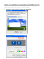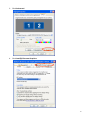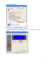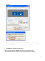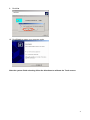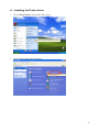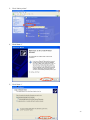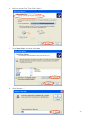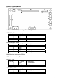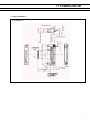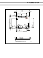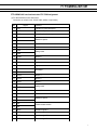
1
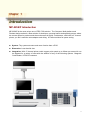
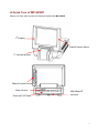
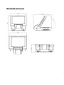
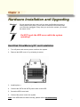
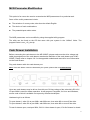
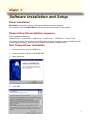
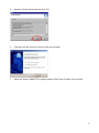
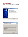
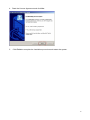
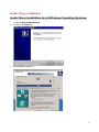
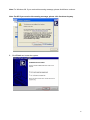
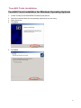
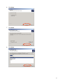
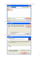
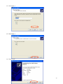
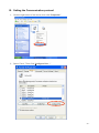
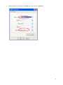
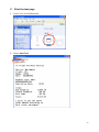
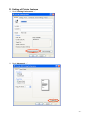
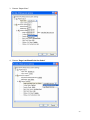
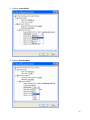
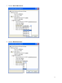
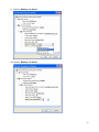
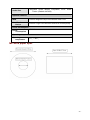
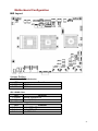
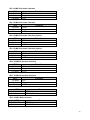
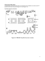
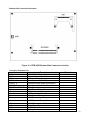
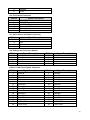
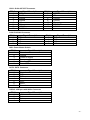
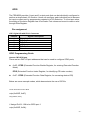
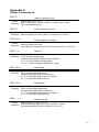
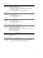
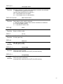
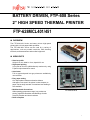
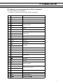
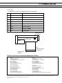
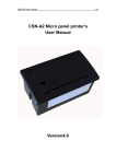
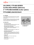
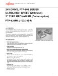
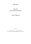
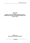
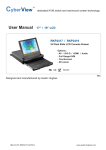
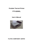
User's Manual
MP-2258
8.4” Fanless Compact POS System
1
Copyright Notice
This document is copyrighted, © 2008. All rights are reserved. Firich Enterprise Co., Ltd
has the right to make improvements of the product described in this manual at any
time without notice.
No part of this manual may be reproduced, copied, translated, or transmitted in any form
or by any means without the prior written permission from Firich Enterprise Co., Ltd.
Information provided in this manual is intended to be accurate and reliable. However,
Firich Enterprise Co., Ltd assumes no responsibility for its use, nor for any
infringements upon the rights of third parties, which may result from its use.
The material in this document is for product information only and is subject to change
without notice. While reasonable efforts have been made in the preparation of this
document to assure its accuracy, Firich Enterprise Co., Ltd, assumes no liabilities
resulting from errors or omissions in this document, or from the use of the information
contained herein.
Safety and Warranty
1. Read these safety instructions carefully.
2. Keep this user's manual for later reference.
3. Disconnect this equipment from any AC outlet before cleaning. Do not use liquid or spray
detergents for cleaning. Use a damp cloth.
4. For pluggable equipment, the power outlet must be installed near the equipment and must be
easily accessible.
5. Keep this equipment away from humidity.
6. Put this equipment on a reliable surface during installation. Dropping it or letting it fall could
cause damage.
7. The openings on the enclosure are for air convection. Protect the equipment from overheating.
DO NOT COVER THE OPENINGS.
8. Make sure the voltage of the power source is correct before connecting the equipment to the
power outlet.
9. Position the power cord so that people cannot step on it. Do not place anything over the
power cord.
10. All cautions and warnings on the equipment should be noted.
11. If the equipment is not used for a long time, disconnect it from the power source to avoid
damage by transient over-voltage.
12. Never pour any liquid into an opening. This could cause fire or electrical shock.
13. Never open the equipment. For safety reasons, only qualified service personnel should open
the equipment.
14. If any of the following situations arises, get the equipment checked by service personnel:
A. The power cord or plug is damaged.
B. Liquid has penetrated into the equipment.
C. The equipment has been exposed to moisture.
D. The equipment does not work well, or you cannot get it to work according to the users
manual.
E. The equipment has been dropped and damaged.
F. The equipment has obvious signs of breakage.
15. DO NOT LEAVE THIS EQUIPMENT IN AN UNCONTROLLED ENVIRONMENT WHERE
THE STORAGE TEMPERATURE IS BELOW -20° C (-4°F) OR ABOVE 60° C (140° F). IT
MAY DAMAGE THE EQUIPMENT.
Table of Content
Chapter 1
3
Introduction
3
MP-2258/P Introduction......................................................................................................... 3
A Quick Tour of MP-2258/P................................................................................................... 4
MP-2258/P Dimension.................................................................................................... 5
Rear I/O Panel....................................................................................................................... 6
Packing List ........................................................................................................................... 6
Chapter 2
7
Hardware Installation and Upgrading
7
Hard Disk Drive/Memory/CF card Installation ................................................................ 7
MCR Parameter Modification ......................................................................................... 8
Cash Drawer Installation ................................................................................................ 8
Chapter 3
Software Installation and Setup
9
9
Driver Installation................................................................................................................... 9
Please follow this installation sequence. ............................................................................... 9
Intel Chipset Driver Installation.............................................................................................. 9
VGA Driver Installation ........................................................................................................ 11
852GM driver installation Windows 2000 & XP ............................................................ 11
Enable second LCD panel setting Windows 2000/Windows XP. ................................. 13
Audio Driver Installation....................................................................................................... 17
Audio Driver Installation for all Windows Operating Systems....................................... 17
TouchKit Tools Installation .................................................................................................. 19
TouchKit Tools Installation for Windows Operating Systems ....................................... 19
TouchKit Control Panel................................................................................................. 22
Chapter 4
Specifications
- 39 -
MP-2258/MP2258P Specifications .................................................................................. - 39 MP-2258 paper spec ....................................................................................................... - 40 Motherboard Configuration.............................................................................................. - 41 -
Chapter 5
Troubleshooting
- 54 - 54 -
Power is on, but there is no Panel Display ............................................................... - 54 Cannot Detect HDD.................................................................................................. - 54 Touch Panel Does not Work..................................................................................... - 55 Fujitsu Touch Panel Cannot Calibrate Correctly ...................................................... - 55 1
MCR is not Functioning Properly.............................................................................. - 55 VFD Display is not Functioning Properly .................................................................. - 55 LAN is not functioning properly................................................................................. - 56 COM1 or COM2 are not functioning properly ........................................................... - 56 Cash Drawer Port is not functioning properly ........................................................... - 57 USB device is not functioning properly..................................................................... - 57 -
Chapter 1
Introduction
MP-2258/P Introduction
MP-2258/P is the most unique one of FEC POS solution. The Compact, Multi-platform and
Fanless design makes it a best solution for boutiques, personal stores and specialty stores, where
the counter space is precious and the environment is stylish. Furthermore, with build in 2” thermal
printer, you don’t need the extra adaptor and wiring. A Perfect solution for space saving.
z System: Tiny system structure and more function than a POS
z Dimension: Less than A4 size
z Integration: With 2” thermal printer could support print speed up to 60mm per second It can
be adapted for a variety of uses with the addition of any of the following options: Magnetic
Card Reader, VFD/LCD customer
3
A Quick Tour of MP-2258/P
Before you start, take a moment to become familiar with MP-2258/P.
1st Display
Identification Device
2” thermal printer
Identification Device
Power Button
External I/O Plate
HDD/Ram/CF
Location
4
MP-2258/P Dimension
5
Rear I/O Panel
I/O Port
Connector Type
Description
DC12V
Connect the adaptor to MP-2258/P
Cash Drawer
DC Power
connector
RJ11 connector
LAN
COM1& COM2
RJ45 connector
RJ45 connector
USB
USB type A
connector
Cash Drawer Connector, 12 V actuation
support
Connect MP-2258/P to the Ethernet
The serial ports COM1 & COM5 can be
used to connect serial devices
Standard USB connector for external
device
Packing List
• MP-2258/P Main System
• Power adapter
• Driver & Manual CD
• MSR to PS/2 Converter cable
• RJ45 to DB9 converter cable X 2
• AC power cord
• Test Paper Scroll
Optional:
•
Identification module
•
Wall mount kits
•
Standalone wiring cover
•
Wall mounted wiring cover
6
Chapter 2
Hardware Installation and Upgrading
Do not remove the rear cover until you have verified that no power is
flowing within the system. Power must be switched off and the power
cord must be unplugged. Every time you service the system, you should
be aware of this.
Do NOT touch the HDD cover while the system
operating!!
Hard Disk Drive/Memory/CF card Installation
1. Turn off power and remove power cord from the system
2. Remove the HDD cover of by releasing 4 screws
3. Install/replace the HDD/Memory/CF to its slot
4. Connect the SATA and SATA power cable to the HDD
5. Screw the HDD cover back
6. Connect the power cord to the system
Note: If the HDD does not work normally, please refer to troubleshooting
7
MCR Parameter Modification
This option is for users who need to customize the MCR parameters for a particular task.
Some of the useful parameters include:
z
The selection of country code, other than the default English.
z
The choice of track combinations.
z
The preamble/post amble codes.
The MCR parameters can be modified by using the supplied utility program.
The utility can be found on the CD that came with your system in the “Utilities” folder. The
program name is msr_v12_win.zip.
Cash Drawer Installation
Before connecting the cash drawer to the MP-2258/P, please make sure the drive voltage and
cable pin assignment of the cash drawer matches the definition of the cash drawer port of MP2258/P. Please refer to chapter 3.8.1 in the appendix motherboard manual for more information
on the Cash Drawer.
Plug cash drawer cable into cash drawer port.
Note: If the cash drawer cannot be detected by the system, please refer to troubleshooting.
Up to two cash drawers may be driven from this port. Driving voltage of the solenoid is DC+12V.
I/O port 280h is used for drawer operation. A test program is supplied, for Linux and Windows,
source code of which is available on request by software developers.
Hardware logic is as follows.
To open drawer1, write 01h to port 280h, wait 200 msec, then write 00h to turn off the drive.
To open drawer2, write 02h to port 280h, wait 200 msec, then write 00h to turn off the drive.
To test for drawer open, read port 280h, if bit 0=1 then drawer is open, if bit 0=0 drawer is closed.
8
Chapter 3
Software Installation and Setup
Driver Installation
MP-2258/P comes with a variety of drivers for different operating systems.
You will find the CD with MP-2258/P which has all necessary drivers for this system.
Please follow this installation sequence.
Driver installation sequence:
Chipset Driver -> VGA Driver -> LAN Driver -> Audio Driver -> USB Driver -> Touch Tools
The reason to follow our sequence is that IRQ settings will be changed by Windows 2000 and XP
to non supported values, and you may encounter unnecessary problems later.
Intel Chipset Driver Installation
1. Insert the CD into your CD ROM Drive.
2. Locate the folder of D:\Driver\CHIPSET\INF
3. Open Setup.exe
4.
Click Next.
9
5.
Read the License Agreement and click Yes.
6.
Click Next and the drivers for the Intel Chip set will install.
7.
When the 'Setup COMPLETE' message appears click Finish to restart your computer.
10
VGA Driver Installation
852GM driver installation Windows 2000 & XP
1. Locate the folder of D:\Driver\VGA\INTEL\WIN2K_XP
2. Open setup.exe
3. Select Next to continue.
11
4. Read the License Agreement and click Yes.
5.
Click Finish to complete the installation procedure and restart the system.
12
Enable second LCD panel setting Windows 2000/Windows XP.
After you have installed the VGA driver you must adjust the settings.
.
1. Right click your mouse anywhere on the desktop then click properties.
2. Click the settings tab.
13
3. Click Advanced.
4. Click Intel(R) Extreme Graphics.
14
5. Click Graphics Properties.
6. Click Extended Desktop and select Notebook for primary device, monitor for secondary
device.
15
7. Click OK.
8. Select the second LCD panel. This is done either by clicking on the number 2 or selecting
from the dropdown menu.
For the second LCD panel make sure that Extend my Windows desktop onto this monitor
is selected.
9. Click Apply then click OK to finish the settings.
Note: During boot sequence “No Sync” will appear on the second LCD panel.
The boot sequence can take a minute or so when a second LCD panel is installed.
16
Audio Driver Installation
Audio Driver Installation for all Windows Operating Systems.
1. Locate D:\Driver\audio\Realtek
2. double click Setup.exe.
3. Select Next to continue.
17
Note: For Windows 2K. If you receive this warning message, please click Yes to continue.
Note: For XP If you receive this warning message, please click Continue Anyway.
4. Click Finish and restart the system.
18
TouchKit Tools Installation
TouchKit Tools Installation for Windows Operating Systems
1.
2.
3.
4.
Locate D:\Utility\TOUCHSCREEN\TouchKit(Fujitsu)\Driver
Select the relevant folder for the operating system that you are using.
Open Setup.exe
Click Next
5. Click Next
19
6. Click Next
7. Click Next
8. Click Next
20
9. Click Yes
10. Click Finish to restart your computer again.
After the system finish rebooting follow the directions to calibrate the Touch screen.
21
TouchKit Control Panel
This section explains the different options in the TouchKit control Panel.
General tab
The general tab allows you to:
•
Change the COM port your touch screen is set to.
•
Calibrate the touch screen with the 4 pts Cal button.
22
Printer Driver Installation Guide
1.
2.
3.
4.
Installing the Printer driver
Setting the Communication protocol
Print the test page
Setting of Printer features
23
A. Installing the Printer driver
1. Click “Control Panel” from WinXP Start menu
2. Click “Printers and other Hardware”
24
3. Click “Add a printer”
4. Click “Next >”
5. Click “Next >”
25
6. Select a printer Port, Then Click “Next >”.
7. Click “Have Disk” and then click next
8. Click “Browse …”
26
9. Browse to the location where the driver file located on the PC, then Click “Open”.
10. Click “OK”
11. Click “Next >”
27
12. Click “Next >”
13. Click “Next >”
14. Click “Finish”
28
15. Click “Continue Anyway”
16. Copy Files …
17. To display the new PrnTek-48 icon.
29
B. Setting the Communication protocol
1. Click the right button of the mouse, then click “Properties”
2. Select “Ports”, Then Click “Configure Port …”
- 30 -
3. Setting the Bits per second to 115200, the Flow control to Xon/Xoff.
- 31 -
C. Print the test page
1. Double click the PrintTest.exe
2. Select “Start Test”
- 32 -
3. Set the page you want to print
- 33 -
D. Setting of Printer features
1. Click “Printing Preferences …”
2. Click “Advanced …”
- 34 -
3. Choose “Paper Size ”
4. Choose “Page Last Blank Print Out Select”
- 35 -
5. Choose “Cutter Mode”
6. Choose “Density Mode”
- 36 -
7. Choose “Black Mark Select”
8. Choose “Mark Dark Value”
- 37 -
9. Choose “Midway Cut Select”
10. Choose “Midway Cut Select”
- 38 -
Chapter 4
Specifications
MP-2258/MP2258P Specifications
System Configuration
CPU (BGA 478)
INTEL® ULV Celeron-M 1GHz w/0KB L2
Chipset
i82852GM GMCH
South Bridge
INTEL 82801DB (ICH4)
Memory
One 200-pin SODIMM support DDR SDRAM up to 1GB
VGA controller
Integrated in 852GM, shares system memory up to
32MB
LCD Panel
8” TFT LCD Panel support resolution 800X600
Touch Panel
Fujitsu 4-wire resistive touch panel
Storage
Internal 2.5” SATA hard disk drive
Type I/II Compact Flash™ Disk with IDE interface
Power
60W/150 watt external power adapter
I/O Port
Serial Port
2 User available COM ports (COM1 & COM2)
2 System assigned COM ports (COM3 & COM4)
¾ COM3 for Touch Screen
¾ COM4 for Build-In Thermal Printer
USB port
4 User available USB 2.0 ports
2 System assigned USB ports
Cash drawer port
RJ11 Cash drawer port, 12V actuation. Controlled
through DIO port 280H
LAN Port
10/100Mbps Ethernet Controller, Realtek RTL8100C
VGA Port
Standard VGA Port for second LCD panel.
- 39 -
Audio Port
Integrated Sound Blaster compatible, AC97 Audio
Codec. (Realtek ALC655)
Optional Features
MSR
External Magnetic Stripe Card Reader track 1/2/3
Identification
Device
External Finger Print Receiver and RFID receiver(USB)
Power Consumption
Power
consumption
30W Idle
Operating temperature
Operating
temperature
0 ℃ ~ 40 ℃
MP-2258 paper spec
- 40 -
Motherboard Configuration
M/B Layout
Jumper Setting
JP1: ATX & AT Mode Selection
JP2
1-2 Short
2-3 Short
Function
ATX Mode Ì
AT Mode
JP2: CMOS Clear
JP2
1-2 Short
2-3 Short
Function
Normal Operation Ì
Clear CMOS Contents
JP3: TFT LCD Voltage Selection
JP3
1-2 short
3-4 short
5-6 short
Function
+3.3V TFT LCDÌ
+3.3V TFT LCD
+5V TFT LCD
- 41 -
JP5: COM3 RI function Selection
JP5
1-2 short
3-4 short
5-6 short
Function
+5VÌ
Ring In
+12V
JP6: COM4 RI function Selection
JP6
1-2 short
3-4 short
5-6 short
Function
+5VÌ
Ring In
+12V
JP8: COM5 RI function Selection (Option)
JP8
1-2 short
3-4 short
5-6 short
Function
+5V
Ring InÌ
+12V
JP9: COM6 RI function Selection (Option)
JP9
1-2 short
3-4 short
5-6 short
Function
+5V
Ring InÌ
+12V
JP10: COM2 RI function Selection
JP10
1-2 short
3-4 short
5-6 short
Function
+5V
Ring InÌ
+12V
JP11: COM1 RI function Selection
JP11
1-2 short
3-4 short
5-6 short
Function
+5V
Ring InÌ
+12V
JP12: COM2 Mode Selection
JP12
1-2, 3-5, 4-6 short
1-3, 2-4 short
Mode
VFD Mode
RS-232 ModeÌ
JP13: COM1 Mode Selection
JP13
Mode
1-2, 3-5, 4-6 short VFD Mode
1-3, 2-4 short
RS-232 ModeÌ
- 42 -
Connector Allocation
I/O peripheral devices and flash disk are connected to the interface connectors and CF
socket on this board computer (Figure 2-2 and Figure 2-3).
Top-Side Connector Allocation:
Figure 2-2 FEB-8522 Top-Side Connector Location
- 43 -
Bottom-Side Connector Allocation:
Figure 2-3 FEB-8522 Bottom-Side Connector Location
Connector Function List
Connector
CN6
CN7
CF1
COM 1, 2
COM 3, 4
COM 5, 6
CPUFAN, SYSFAN
J1
J2
J3, J8
J4
J5
J6
Function
+12V DC-In Power Connector
Digital I/O with RJ-11 Connector
Compact Flash Connector
Serial port with RJ-45 Connectors
Serial port with Wafer Connectors
Serial port with Wafer Connectors
Fan Connectors
+8V Power Output Connector
PS2 Keyboard & Mouse Connector
USB port with Wafer Connectors
Speaker out Connector
+5V Power output Connector
LVDS Inverter Power Connector
J7
J13
J17
J18
+12V Power output Connector
Front Panel Connector
SATA Power Connector
Debug Connector
Remark
Option
- 44 -
LVDS1
VGA1
LAN
SW1
SATA
USB1 & 2
LVDS LCD Panel Connector
D-Sub15P CRT Connector
RJ45 LAN Connector
Power Button Switch
SATA Connector
USB dual port Connectors
CN6: +12V DC-In Power Connector
PIN No.
1
2
3
4
Signal Description
+12V DC-In
Ground
+12V DC-In
Ground
CN7: Digital I/O with RJ-11 Connector
PIN No.
1
2
3
4
5
6
Signal Description
Ground
DIO Out 0
DIO IN 0
+12V
DIO Out 1
Ground
CF1: Compact Flash Connector
PIN No.
1
2
3
4
5
6
7
8
9
10
11
12
13
14
15
16
17
18
19
20
21
22
Signal Description
Ground
Data 3
Data 4
Data 5
Data 6
Data 7
Select 0
Ground
Ground
Ground
Ground
Ground
+5V
Ground
Ground
Ground
Ground
SA2
SA1
SA0
Data 0
Data 1
PIN No.
26
27
28
29
30
31
32
33
34
35
36
37
38
39
40
41
42
43
44
45
46
47
Signal Description
Ground
Data 11
Data 12
Data 13
Data 14
Data 15
Select 1
N/C
IO Read
IO Write
Pull Up to +5V
IRQ 15
+5V
Slave/Master# Select
N/C
Reset
IORDY
DMA REQ
DMA ACK#
IDE Active
Pull Up to +5V
Data 8
- 45 -
23
24
25
Data 2
Pull Up to +5V
Ground
48
49
50
Data 9
Data 10
Ground
COM1/2: Serial port with RJ-45 Connectors
PIN No.
1
2
3
4
5
6
7
8
Signal Description
RI/+5V/+12V
CTS/+5V/+12V
Ground
RTS/ Ground
DTR
DSR
TXD
RXD
COM3/4: Serial port with Wafer Connectors
PIN No.
1
3
5
7
9
Signal Description
DCD
RXD
TXD
DTR
Ground
PIN No.
2
4
6
8
10
Signal Description
DSR
RTS
CTS
RI/+5V/+12V
N/C
COM5/6: Serial port with Wafer Connectors (Option)
PIN No.
1
3
5
7
9
Signal Description
DCD
RXD
TXD
DTR
Ground
PIN No.
2
4
6
8
10
Signal Description
DSR
RTS
CTS
RI/+5V/+12V
N/C
CPUFAN/SYSFAN: Fan Connector
PIN No.
1
2
3
Signal Description
Ground
Fan Power (+12V)
Speed Pulse Output
J1: +8V Power Output with Wafer Connector
PIN No.
1
2
3
4
5
6
Signal Description
Ground
+8V
Ground
+8V
Ground
+8V
- 46 -
J2: PS2 Keyboard & Mouse with Wafer Connector
PIN No.
1
2
3
4
5
6
Signal Description
+V5
KBCLK
KBDATA
Ground
MSCLK
MSDATA
J3, J8: USB port with Wafer Connectors
PIN No.
1
2
3
4
Signal Description
+5V
DataData+
Ground
J4: Speaker Output with Wafer Connector
PIN No.
1
2
3
4
Signal Description
Speaker output Right +
Speaker output Right Speaker output Left +
Speaker output Left -
J5: +5V Power Output with Wafer Connector
PIN No.
1
2
3
4
5
6
Signal Description
Ground
+5V
Ground
+5V
Ground
+5V
J6: LVDS Panel Inverter Power Connector
PIN No.
1
2
3
4
5
Signal Description
+12V
+12V
Ground
Ground
Back Light Enable
J7: +12V Power Output with Wafer Connector
PIN No.
1
2
3
4
Signal Description
Ground
+12V
Ground
+12V
- 47 -
5
6
Ground
+12V
J13: Front Panel Connector
PIN No.
1
2
3
4
5
6
Signal Description
+5V (470 ohm)
HDD LED
+5VSB (470 ohm)
Suspend LED
Ground
Reset Switch
J17: SATA Power with Wafer Connector
PIN No.
1
2
3
4
Signal Description
+5V
+5V
Ground
Ground
J18: Debug port Connector (Option)
PIN No.
1
3
5
7
9
Signal Description
Data0
Data1
Data2
Data3
Ground
PIN No.
2
4
6
8
10
Signal Description
Data4
Data5
Data6
Data7
N/C
PIN No.
2
4
6
8
10
12
14
16
18
20
22
24
26
28
30
Signal Description
Ground
Data A3Clock AData A2Data A1Data A0Ground
Data B3Clock BData B2Data B1Data B0Ground
LVDS VDD
LVDS VDD
LVDS1: LVDS Panel Signals Connector
PIN No.
1
3
5
7
9
11
13
15
17
19
21
23
25
27
29
Signal Description
Ground
Data A3+
Clock A+
Data A2+
Data A1+
Data A0+
Ground
Data B3+
Clock B+
Data B2+
Data B1+
Data B0+
Ground
LVDS VDD
LVDS VDD
- 48 -
VGA1: D-Sub15P CRT Connector
PIN No.
1
3
5
7
9
11
13
15
Signal Description
RED
BLUE
Ground
Ground
NC
ID1
HSYNC
DDCCLK
PIN No.
2
4
6
8
10
12
14
Signal Description
GREEN
ID0
Ground
Ground
Ground
DDCDATA
VSYNC
LAN: RJ45 LAN Connector
PIN No.
1
3
5
7
Signal Description
TXD+
RXD+
N/C
N/C
PIN No.
2
4
6
8
Signal Description
TXDRXDN/C
N/C
SW1: Power Button Switch
PIN No.
1
2
3
4
5
6
Signal Description
Ground
Ground
Power on signal
Power on signal
Standby LED
Power LED
SATA: SATA Connector
PIN No.
1
2
3
4
5
6
7
Signal Description
Ground
TXD+
TXDGround
RXDRXD+
Ground
USB1/2: USB port with Wafer Connector
PIN No.
1
2
3
4
Signal Description
+5V
DataData+
Ground
- 49 -
GPIO
The FEB-8522 provides 1 input and 2 output ports that can be individually configured to
perform a simple basic I/O function. Users can configure each individual port to become
an input or output port by programming register bit of I/O Selection. To invert port value,
the setting of Inversion Register has to be made. Port values can be set to read or write
through Data Register.
Pin assignment
CN7: Digital I/O with RJ-11 Connector
PIN No.
1
2
3
4
5
6
Signal Description
Ground
DIO Out 0
DIO IN 0
+12V
DIO Out 1
Ground
GPIO Programming Guide
Access CN7 GPIO port
There are two PNP I/O port addresses that can be used to configure GPIO ports,
z
0x2E - EFER (Extended Function Enable Register, for entering Extended Function
Mode)
EFIR (Extended Function Index Register, for identifying CR index number)
z
0x2F - EFDR (Extended Function Data Register, for accessing desired CR)
Below are some example codes, which demonstrate the use of GPIOs.
// Enter Extended Function Mode
outp (0x002E, 0x87);
outp (0x002E, 0x87);
// Assign Pin121-128 to be GPIO port 1
outp (0x002E, 0x2A);
- 50 -
outp (0x002F, 0x0FF);
// Select Logic Device 7
outp (0x002E, 0x07);
outp (0x002F, 0x07);
// Active Logic Device 7
outp (0x002E, 0x30);
outp (0x002F, 0x01);
// Select Inversion Mode
outp (0x002E, 0xF2);
outp (0x002F, Inversion Register);
// Select I/O Mode
// Bit0~bit3 output and bit4~bit7 input
outp (0x002E, 0xF0);
outp (0x002F, 0xF0));
// Access GPIO ports
outp (0x002E, 0xF1);
outp (0x002F, (Output Data & 0x03));
or Input Data = (inp (0x002F) & 0x10);
// Exit Extended Function Mode
outp (0x002E, 0xAA);
Definitions of Variables:
- 51 -
Each bit in the lower nibble of each Register represents the setting of a GPIO port.
Bit0 vs. GPIO DIO_OUT0
Bit1 vs. GPIO DIO_OUT1
Bit4 vs. GPIO DIO_IN0
Value of Inversion Register:
Only lower nibble is available for this function.
When set to a ‘1’, the incoming/outgoing port value is inverted.
When set to a ‘0’, the incoming/outgoing port value is the same as in Data Register.
Value of I/O Selection Register:
Only lower nibble is available for this function.
When set to a ‘1’, respective GPIO port is programmed as an input port.
When set to a ‘0’, respective GPIO port is programmed as an output port.
Value of Output Data / Input Data:
Only lower nibble is available for this function.
If a port is assigned to be an output port, then its respective bit can be read/written.
If a port is assigned to be an input port, then its respective bit can be read only.
Note:
Some other functions may occupy the high nibble of the registers. Altering any content in
high nibble will be undesired.
- 52 -
Printer Control Board
Connector Allocation
J1: ISP On Board Programming, 6Pins,90degree
J2: RS232, 6Pins
Pin No.
1
2
3
4
Define
GND
RXD
TXD
BUSY
J3: Power input, 5Pins
Pin No.
Define
1
+5V
2
GND
3
GND
4
+8V
5
+8V
Description
Description
< 200 mA
3.0Amp, max
3.0Amp, max
J4: Mechanism connector, 30Pins
J5: Cutter connector , 8Pins
J6: LED, 3Pins
Pin No.
1
2
3
Define
Led-1
GND
Led-2
Description
+5Vindication
J7: BUTTON, 2Pins
Pin No.
1
2
Define
SW1
GND
Description
Paper feed
Status
- 53 -
Chapter 5
Troubleshooting
Please note that the following troubleshooting guide is designed for people with strong computer
hardware knowledge such as System Administrators and Engineers.
Power is on, but there is no Panel Display
1.
Check that the motherboard Power LED is on when the power adapter power switch is in the
on position.
Ensure that the correct AC voltage is selected (the voltage switch is located beside the power
switch).
2.
Check that the Power are running when system power is on.
A.
Check whether the ATX power switch cable is properly connected to motherboard CN2
(Please refer to Page 2-2 in the FEB-8522 User’s Manual).
3.
Please ensure that the SATA cable is properly connected to the HDD.
4.
Reset CMOS DATA by shorting motherboard JP1 PIN2 and PIN3 for a few seconds (Please
refer to Page 3-2 in the FEB-8522 User’s Manual).
5.
Check if the system is beeping.
A.
A single long repeated beep indicates that a DRAM error has occurred. Make sure
DRAM is properly installed or replace DRAM.
B.
One short beep after power on, means system is ok, but LCD panel or VGA interface
could be defective.
i.
INIT display should be set for AGP in the COMS setup.
ii.
LVDS board connection to motherboard LVDS1 could be defective.
iii.
The connection between the LVDS board and the LCD panel is not completely.
iv.
The LCD cable could be defective.
v.
The Inverter cannot produce backlight.
vi.
The LCD panel could be defective.
To check where the problem could be:
Please connect a VGA monitor to the VGA port. If the VGA monitor is display normally, one of the
problems above is occurring, otherwise it could be the motherboard is not functioning properly.
Cannot Detect HDD
1.
SATA cable is not connected properly to motherboard SATA Connector or it could be
defective.
2.
Check CMOS setup, set SATA HDD to Auto detects.
3.
On-board SATA port could be defective.
- 54 -
Touch Panel Does not Work
1.
Check CMOS settings, COM3 needs to be “Enabled”. The correct settings are “3E8h” and
“IRQ10”.
2.
Check if there are no conflicts between COM3 IRQ10 and any other devices.
3.
Check the TouchKit driver has been properly installed. Or try to re-install again (Please refer
to the TouchKit driver installaion).
4.
Check the TouchKit driver on COM3 has been detected during the TouchKit driver installation.
If yes, than check that the flat cable from the TOUCHKIT touch screen has been properly
connected to the TouchKit controller.
5.
Check the TouchKit controller Green LED is blinking?If no, there is no DC+5V support for the
TouchKit controller from the motherboard.
A.
6.
Check that the COM3 cable is properly connected between motherboard and the Touch
screen controller.
Touch screen controller could be defective or the touch panel could be defective.
Fujitsu Touch Panel Cannot Calibrate Correctly
1.
Please replace the Fujitsu controller, and re-calibrate. If this works, change back to the
original Fujitsu controller, and re-calibrate.
2.
If the Fujitsu touch panel still cannot calibrate correctly after changing to a new Fujitsu
controller, the touch panel may be not installed properly or it could be defective.
MCR is not Functioning Properly
1.
Check if the green MCR LED is on.
Check if the MCR is properly connected to the MCR connector board on main system.
2.
A.
Make sure the 6 wire cable is properly connected between 9000PB0610 I/O board
CN20 and the MCR connector board.
B.
The MCR connector board could be defective.
C.
The MCR module could be defective.
If a keyboard is connected to the PS/2 keyboard port, and functions correctly, then the MCR
module could be defective.
VFD Display is not Functioning Properly
1.
Ensure that COM4 is enabled in the CMOS setup, and data is written to COM4 in the
application.
2.
Check if there is any display when system power is ON, if the screen is blank, please follow
the steps below.
A.
Make sure the power switch on the VFD display is on before powering the main system.
B.
Make sure that the motherboard JP4 & JP5 jumper settings are correct.
The proper settings are:
JP4 Pins 1-2 shorted
- 55 -
JP5 Pins 1-2, Pins 3-5 and Pins 4-6 shorted
3.
The on-board COM4 I/O chips could be defective.
LAN is not functioning properly
1.
Check if the LAN driver is installed properly. (Please refer to the LAN driver installation)
2.
Check if there are any IRQ conflicts.
3.
Check if the RJ45 cable is properly connected.
4.
The on board LAN chip could be defective.
COM1 or COM2 are not functioning properly
1.
Check if the I/O ports are enabled in the CMOS setup.
2.
Check if there are any IRQ conflicts.
3.
The motherboard could be defective.
- 56 -
Cash Drawer Port is not functioning properly
1.
Make sure the pin assignment matches between the cash drawer and the RJ11 cash drawer
port.
2.
Verify the digit I/O port address and bit are “280h” respectively. Command send “L” level for
200ms (Refer to FEB-8522 User’s Manual).
3.
The motherboard could be defective.
USB device is not functioning properly
1.
Ensure that the USB controller is “enabled” in the CMOS setup.
2.
Ensure that the USB Legacy is “enabled” in the CMOS setup. (Windows 98、Windows
2000、Window XP Professional)
3.
Ensure that the USB Legacy is “Disabled” in the CMOS setup. (Embedded OS: Windows XP
Embedded、Window CE. NET、Linux RedHat 9)
- 57 -
Appendix A
Printer Command List
ESC+'2'
Code
Function
ESC+'0'
Code
Function
ESC+'A'+’n’
Code
Function
ESC+'-'+n
Code
Function
16-dot Line Spacing ( 2 mm )
0x1B + 0x32, or 27 + 50
Sets line spacing to 16 dots. (16dot x 0.125mm/dot = 2 mm)
This is the default setting.
4-dot Line Spacing ( 0.5 mm )
0x1B + 0x30, or 27 + 48
Sets line spacing to 4 dots. (4dot x 0.125mm/dot = 0.5 mm)
n-dot Line Spacing ( 0~32 mm )
0x1B + 0x41 + n, or 27 + 65 + n
Sets line spacing to n dots.
n can take on a value from 0 to 0xFF (0 to 255 dot line = 0~32 mm).
Underline
0x1B + 0x2D + n, or 27 + 45 + n
Turns on/off underline mode.
Only the least significant three bits are valid for n.
n = 0: Turn off underline mode(default)
n =1 to 7: Set the underline thickness to n dots.
ESC+'W'+n
Double-Width
Code
Function
0x1B + 0x57 + n, or 27 + 87 + n
Turns on/off double-width mode.
Only the least significant bit is valid for n.
n = 0: Turns double-width mode off. (default)
n = 1: Turns double-width mode on.
ESC+'w'+n
Double-Height
Code
Function
0x1B + 0x77 + n, or 27 + 119 + n
Turns on/off double-height mode.
Only the least significant bit is valid for n.
n = 0: Turns double-height mode off. (default)
n = 1: Turns double-height mode on.
ESC+ ‘ ' + n
Code
Function
Character spacing
0x1B + 0x20 + n, or 27 + 32 + n
Sets the character spacing to n dots.( default = 4 Dots)
The least significant 7 bits are valid for n. (0 to 127)
- 58 -
ESC+'I'+n
Code
Function
Reverse
0x1B + 0x57 + n, or 27 + 87 + n
Turns on/off reverse mode.
Only the least significant bit is valid for n.
n = 0: resets the reverse mode (prints black characters on a white
background), (default).
n = 1: prints white characters on a black background.
ESC+'B'+n
Code
Function
Bold
0x1B + 0x42 + n, or 27 + 66 + n
Turns on/off Bold mode.
n = 0: Turns Bold mode off. (default)
n = 1: Turns Bold mode on.
ESC+'T'+n
Code
Function
Italic
0x1B + 0x54 + n, or 27 + 84 + n
Turns on/off Italic mode.
n = 0: Turns Italic mode off. (default)
n = 1: Turns Italic mode on.
ESC+'V'+nl+nh+Image Data
Code
Function
0x1B + 0x56 + nl+ nh + Image Data, or
27 + 86 + nl + hn + Image Data
nl, nh: number of dot lines in the vertical direction.
nl represents the least significant byte , nh represents the most significant byte.
Number of dot lines = nh × 256+nl
Image Data = 48 x nhnl Bytes.
0 <= nhnl <= 0xFFFF (65535)
DC2+'~'+n
Code
Function
Print Density Specify
0x12 + 0x7E + n, or 18 + 126 + n
Sets print density.
n: 70 - 130
CR : Carriage Return
Code
Function
Bit Image Specify
Carriage Return
0x0D or 13
Prints the contents of the line buffer in the currently selected print
mode, and then feeds paper a predefined distance.
59
DC2+'p'+n
Code
Function
Out-of-paper Select
0x12 + 0x70 + n, or 18 + 112 + n
Specifies whether or not the error processing operation is performed
when an out-of paper error occurs.
Only the least significant bit is valid for n.
n=0 : Out-of-paper error is invalid.
n=1 : Out-of-paper error is valid (default).
DC2+'m'+s+nl+nh
Code
Function
ESC+'@'
Code
Function
ESC+'i'
Code
Function
ESC+'m'
Code
Function
ESC+'J'+ n
Code
Function
ESC+'j'+ n
Code
Function
Mark Position Detect
0x12 + 0x6D + s + nl + nh, or 18 + 109 + s + nl + nh
Feeds paper until a mark is detected.
s : sets the direction of paper feed, and the conditions of stoppage.
s = 0, stop on Mark Position.
s = 1, stop Mark Position after.
Reset
0x1B + 0x40, or 27 + 64
Reset on 500 ms after.
Full cut
0x1B + 0x69, or 27 + 105
Cut the paper fully.
Partial cut
1B + 6D, or 27 + 109
Cut the paper partially.
Feed Forward
0x1B + 0x4A + n, or 27 + 74 + n
Feeds the paper forward.
n can take on a value from 0 to 0xFF (0 to 255 dot line).
Feed Backward
0x1B + 0x6A + n, or 27 + 106 + n
Feeds the paper backwards.
n can take on a value from 0 to 0xFF (0 to 255 dot line).
60
DC3 + 'B' + 'R' + n
Code
Function
0x13 + 0x42 + 0x52 + n, or 19 + 66 + 82 + n
It will available after power on rest.
n = '1' : Select 115200 <default , 115200 n 8 1>
n = '2' : Select 230400
DC3 + 'N' + n
Code
Function
Select Baud Rate
Select character code table
0x13 + 0x4E + n, or 19 + 78 + n
Select a character code table
n = 0x00 : ASCII(0x20~0x7F) + 0x80 ~ 0Xff
n = 0x01 : ASCII(0x20~0x7F) + GB-2312
0x8020~0xF8FF (Low Byte:0x20 ~ FF)
DC3 + 's'
Code
Function
Enquiry Print Status
0x13 + 0x73, or 19 + 115
Enquiry the print status.
The return value:
0x30, ‘0‘
0x31, ‘1’
0x32, ‘2’
0x33, ’3’
0x34, ‘4’
0x35, ‘5’
0x36, ‘6’
0x37, ‘7’
0x38, ‘8’
0x41, ‘A’
Hardware error
Head-up error
Vp Voltage error
Auto-cutter error
Thermal head Temperature error
None
Paper end
During printing
Print-ready status
Paper near end
61
DC3 + 'v'
Code
Function
Enquiry Vp Voltage
0x13 + 0x76, or 19 + 118
Measures the Vp voltage (power voltage for head).
The voltage is represented by hexadecimal 4-byte characters
consisting of a 2-digit integer, decimal point and first decimal place
figure.
Example: 8.0 V
: ’8.0’(3816, 2E16, 3016)
7.5V
: ’7.5’(3716, 2E16, 3516)
If the voltage is out of the Vp voltage tolerance (4.5 to 9.0 V), an error
occurs and you cannot enter any function code and data.
DC3 + 'r'
Enquiry Firmware Version
Code
Function
0x13 + 0x73, or 19 + 115
Enquiry the printer firmware version.
The version is represented by hexadecimal 4-byte.
Ex: v100
DC3 + 'm'
Enquiry Checksum
Code
Function
0x13 + 0x6D, or 19 + 109
Enquiry the checksum of the ROM content.
The value is represented by hexadecimal 4-byte.
EX: 06C0 (HEX)
GS+'k'+ n + DATA + NUL
Code
Function
Bar Code Print Select
1D + 6B + n + DATA + 0 or 29 + 107 + n + DATA + 0
Convert data to a bar code according to the specified code and print it.
Only the least significant 4 bits of n are valid.
n=0: UPC A : Input one of '0' to '9' 11 times, then input 0.
n=1: UPC E : Input one of '0' to '9' 11 times, then input 0.
n=2: EAN 13 : Input one of '0' to '9' 12 times, then input 0.
n=3: EAN 8 : Input one of '0' to '9' 7 times, then input 0.
n=4: CODE 39 : Input one of ' ','$','%','+','-','.','/','0'to'9','A'to'Z' a given
number of times, then input 0.
n=6: CODABAR : Input a start character 'A' to 'D', one of '0' to '9', '+',
'.', '/', ':', '$', '-', a given number of times, a stop character 'A' to 'D',
then input 0.
n=8: CODE 128 : Input a start code 103 to 105, 0 to 102 a given
number of times, then input 255.
If n is out of range, this command is ignored.
62
GS+'w'+n1+n2
Code
Function
GS+'P'+n
Code
Function
GS+'h'+n
Code
Function
Narrow
0x1D + 0x77 + n1 + n2, or 29 + 119 + n1 + n2
Sets narrow and wide width of a bar code with number of dots.
n1 = 0 to 2 : Narrow width
0 = 2 dots
1 = 3 dots
2 = 4 dots
n2 = invalid (does not care)
Bar Code Print Position
0x1D + 0x50 + n, or 29 + 80 + n
Sets a print position of a bar code.
n=0 : Left (default)
n=1 : Center
n=2 : Right
Bar Code Height
0x1D + 0x68 + s + n, or 29 + 104 + n
Sets height of the bar code.
n=1 to 255 : Height of the bar code (Unit : dot line)
n=95 (default)
0
battery driveN, FTP-608 Series
2” high speed thermal printer
FTP-628MCL401/451
n Overview
The FTP-628 MCL Series are battery driven high-speed
printers with a 2-inch paper width equivalent.
The FTP-628 MCL Series can be used for a variety of
applications, such as portable terminals, POS, banking
terminals, and measurement and medical equipment.
n highlights
• Ultra low profile
Height 21.8 mm, width 81.2 mm, depth 42.2 mm
FTP-628MCL401
• High speed printing
It can print at 60 mm/s (480 dotlines/s) maximum by using
Fujitsu's unique head drive control.
• Auto Cutter
Full cut type and partial cut type printers are available by
user selection.
• Easy paper setting
Our unique platen release mechanism allows a wide paper route even if the printer is ultra-compact, so paper can be easily inserted. Conventional auto loading is also available.
• Multifunctional die-cast form
Wide operating temperature range, long continuous printing, high ESD absorbtion and discharge of static electricity vibration and shock resistant.
FTP-628DSL491R
• RoHS compliant
FTP-628MCL401/451
n Part numbers
Name
Part Number
Printer mechanism with cutter
FTP-628MCL401 (Easy Load Model)
Printer mechanism without cutter
FTP-628MCL451 (Easy Load Model with platen bracket + lock
lever)
LSI for driving
FTP-629CU451R
Interface board for
Mechanism/Cutter
Cutter supported
Interface cable
Parallel (Centronics) FTP-628Y202
Power cables
FTP-628DSL491R Parallel (Centronics) / Serial (RS-232C)
Serial (RS-232C)
FTP-628Y302
Head, motor, logic
FTP-628Y402
nSPECIFICATIONS
Item
Specifications
Part number
FTP-628MCL401
Printing method
Thermal-line dot method
Dot structure
384 dots/line
Dot pitch (Horizontal)
0.125 mm (8 dots/mm)—Dot density
Dot pitch (Vertical)
0.125 mm (8 dots/mm)—Line feed pitch
Effective printing area
48 mm
Number of columns
ANK 32 columns/line (maximum 12 x 24 dot font)
Paper width 58 mm
Paper thickness
60 to 100 µ m (some paper in this range may not be used because of paper characteristics)
Printing Speed
Maximum 60mm/sec. (480 dot line/sec.) at 8.5V
Character types
Alphanumeric, kana: 159 types
International characters: 195 types
JIS Kanji (Kanji CG loaded board):
about 6800 types
Character, dimensions (W×H), number
12
× 24 dots, (1.5 × 3.0 mm), 32 columns: ANK
of columns
24 × 24 dots, (3.0 × 3.0 mm), 16 columns: ANK
8 × 16 dots, (1.0 × 2.0 mm), 48 columns: ANK
16 × 16 dots, (2.0 × 2.0 mm), 24 columns: ANK
FTP-628MCL401/451
nSPECIFICATIONS
Item
Interface
Power
supply
Dimensions
Weight
Life
Conforms to RS232C / Centronics
For print head
4.2 - 8.5 VDC average current, 1.8 (2.4)A at 7.2V
(print ratio: 12.5%, print speed: 60mm/sec. )
For motor
4.2 - 8.5 VDC, 1A maximum
For cutter motor
4.75 - 8.5 VDC, 1A maximum
For logic
5 VDC ± 5%, 0.1 A maximum
Mechanism with cutter
81.2 x 42.2 x 21.8 mm (WxDxH)
Interface board
70 x 60 x12 mm
Mechanism with cutter
Approximately 97g
Interface board
Approximately 25g
Head
Pulse resistance: 100 million pulses/dot (under our standard
conditions); Abrasion resistance: paper traveling distance 50km
(print ratio: 12.5% or less)
Cutter
500,000 cuts
Platen
5,000 times (open/close)
Operating temperature*
0˚ C to 50˚ C
Operating humidity
Operating
environment Storage temperature
Detection
function
Specification
20 to 85% RH (no condensation)
-20˚ C to +60˚ C (paper not included)
Storage humidity
5 to 95% RH (no condensation)
Head temperature
detection
Detected by thermistor
Paper out/mark detection
Detected by photo-interrupter
Platen release
Detected by sliding switch
Movable blade
Detected by photo-interrupter
Recommended thermal sensitive paper
High Sensitive Paper
TF50KS-E4 (Nippon Paper)
Standard paper:
TF60KS-E(Nippon Paper), FTP020PU001 (58mm), PD105R (Oji Paper),
FTP-020P0701 (58mm)
Medium Life Paper
TF60KS-F1, FTP-020P0102 (58mm),
PD170R (Oji Paper), P220VBB-1
Mitsubishi Paper)
Long Life Paper
PD160R-N (Oji Paper), AFP-235
(Mitsubishi Paper), TP50KJ-R (Nippon
Paper), HA220AA (Nippon Paper)
*+5˚C to +40˚C printing density assurance rance (-25 to 70˚C capability)
FTP-628MCL401/451
n FUNCTION OF INTERFACE BOARD
Item
Item
1.
Test print function
8.
Cutter trouble detect
2.
Paper out detection
9.
Motor power saving function
3.
Paper near end detection
10.
Mark detection function
4.
Platen open detection
11.
MCU operation abnormality detection
5.
Thermal head temperature abnormality detection
12.
Power ON/OFF sequence protection
6.
Blow-out fuse detection
13.
Motor over-current protection
7.
Head voltage abnormality detection
14.
Hardware timer
n dimensions
1. Printer mechanism
(54)
FTP-628MCL401
5.4
printer position standard
platen center
lever
pa
pe
r
platen unit
8.2
10.7
2.8
platen unit
paper exhaust position
42.2
3.9
7.5
cutting position
3.
printer
Unit: mm
Note: 1. Dimensions are nominal value (tolerance ±5 unless otherwise specified).
2. Platen unit (lever, platen, etc) moves by approximately 0.7mm toward paper insertion direction when platen is open.
FTP-628MCL401/451
1. Printer mechanism
FTP-628MCL451
FTP-628MCL401/451
2. Interface board
(70.0)
63.5
3.25
3.25
50.5
.0
3.25
25.5
.45
30
CN8
2
CN3
8
29
45.5
CN
30
CN2
6
3.5
CN7
.2
8
.25
17.5
3
7
49.5
Mounting height
Mounting height
Note:
. The size with parentheses is a reference value.
2. Part mounting height is maximum.
.6
3.25
2
53.5
42.0
3-Ø3.2
FGØ3.2
3.25
(60.0)
CN4
Unit:mm
FTP-628MCL401/451
FTP-628MCL401 mechanism/cutter FPC PIN Assignment
(1)For thermal head, motor and sensor
Connector on control circuit: 52610-3090 (Molex or equivalent)
No
Signa l
Content s
1
PH K
Cathode for photo interrupto r
2
VSE N
paper sensor powe r
3
PH E
Emittor for photo interrupto r
4
VH
5
VH
6
DI
Data i n
7
CL K
Cloc k
8
GN D
9
GN D
10
STB 6
Strobe 6
11
STB 5
Strobe 5
12
STB 4
Strobe 4
13
Vd d
Logic powe r
14
TM
15
TM
16
STB 3
Strobe 3
17
STB 2
Strobe 2
18
STB 1
Strobe 1
19
GN D
20
GN D
21
LA T
Data latc h
22
DO
Data ou t
23
VH
24
VH
25
SW
36
SW
27
MT/ A
Excitation signal A
28
MT/ A
Excitation signal A
29
MT/ B
Excitation signal B
30
MT/ B
Excitation signal B
Head drive power
Head ground
Thermistor
Head ground
Head drive power
Platen release switch
FTP-628MCL401/451
FTP-628MCL451 mechanism/platen bracket FPC PIN Assignment
(1)For thermal head, motor and sensor
Connector on control circuit: 52610-3090 (Molex or equivalent)
No
Signa l
Content s
1
PH K
Cathode for photo interrupto r
2
VSE N
paper sensor powe r
3
PH E
Emittor for photo interrupto r
4
VH
5
VH
6
DI
Data i n
7
CL K
Cloc k
8
GN D
9
GN D
10
STB 6
Strobe 6
11
STB 5
Strobe 5
12
STB 4
Strobe 4
13
Vd d
Logic powe r
14
TM
15
TM
16
STB 3
Strobe 3
17
STB 2
Strobe 2
18
STB 1
Strobe 1
19
GN D
20
GN D
21
LA T
Data latc h
22
DO
Data ou t
23
VH
24
VH
25
SW
36
SW
27
MT/ A
Excitation signal A
28
MT/ A
Excitation signal A
29
MT/ B
Excitation signal B
30
MT/ B
Excitation signal B
Head drive power
Head ground
Thermistor
Head ground
Head drive power
Platen release switch
FTP-628MCL401/451
(2)For cutter
Connector on control circuit: 52610-0890 (Molex or equivalent)
No
Signa l
Content s
1
VSE N
Home position sensor powe r
2
PH E
Emittor for photo interrupto r
3
PH K
Cathode for photo interrupto r
4
MT/ A
Excitation signal A
5
MT/ A
Excitation signal A
6
MT/ B
Excitation signal B
7
MT/ B
Excitation signal B
8
NC
Not connecte d
Sensor (Photointerruptor)
Platen unit
Thermal head
Motor
Connector No
(FPC pin
30,29,
FPC
Connect terminal:
surface side
Fujitsu Components International Headquarter Offices
Japan
Fujitsu Component Limited
Gotanda-Chuo Building
3-5, Higashigotanda 2-chome, Shinagawa-ku
Tokyo 141, Japan
Tel: (81-3) 5449-7010
Fax: (81-3) 5449-2626
Email: [email protected]
Web: www.fcl.fujitsu.com
North and South America
Fujitsu Components America, Inc.
250 E. Caribbean Drive
Sunnyvale, CA 94089 U.S.A.
Tel: (1-408) 745-4900
Fax: (1-408) 745-4970
Email: [email protected]
Web: http://us.fujitsu.com/components/
Europe
Fujitsu Components Europe B.V.
Diamantlaan 25
2132 WV Hoofddorp, The Netherlands
Tel: (31-23) 5560910
Fax: (31-23) 5560950
Email: [email protected]
Web: emea.fujitsu.com/components/
Asia Pacific
Fujitsu Components Asia Ltd.
102E Pasir Panjang Road
#01-01 Citilink Warehouse Complex
Singapore 118529
Tel: (65) 6375-8560
Fax: (65) 6273-3021
Email: [email protected]
Web: http://www.fujitsu.com/sg/services/micro/components/
©2007 Fujitsu Components America, Inc. All rights reserved. All trademarks or registered trademarks are the property of their respective owners.
Fujitsu Components America or its affiliates do not warrant that the content of datasheet is error free. In a continuing effort to improve our products Fujitsu Components America, Inc. or its
affiliates reserve the right to change specifications/datasheets without prior notice.
Rev. August 17, 2007