1
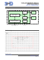
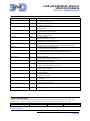
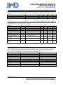
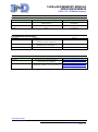
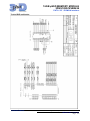
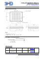
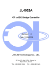
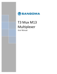
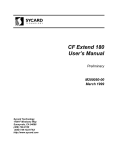
16GB µSSD MEMORY MODULE 3DSS128G16VB2434 PATA / CF / PCMCIA interface Features Storage Capacity: 16 GBytes ATA/IDE, PCMCIA 2.1 and CF 4.1 standard compatible Supports up to PIO Mode-6 Supports up to Multi-Word DMA Mode-4 Supports up to Ultra DMA mode-4 Endurance : 2 millions W/E Hardware ECC : 4 Bytes in a 512 bytes sector Wear levelling Bad block management Flash Single-level cell technology : - Data retention : 10 years - Endurance : 100,000 W/E Data transfer to flash - Sustained read : 40 MB/s - Sustained write : 35 MB/s Power down data protection Flash write protect control SLC Nand Flash Technology 5V or 3.3Vsingle power supply 224 PBGA, pitch 1.27mm Operating temperature: - 0°C to +70°C - -40°C to +85°C - -55°C to +125°C Storage temperature: - -65°C to +150°C Size: 22 x 26 mm Height: 3.7 mm Mass: 4.4gr +/- 0,05 Application Mass storage solution for industrial products General Description The 3DSS128G16VB2434 is a high-density, high-performance, fully integrated, embedded flash Solid State Drive. It combines a Controller and two SLC Nand Flash integrated in a compact BGA package. This product is tolerant to shocks and supports industrial temperature for applications requiring high reliability. The endurance of the SLC FLASH is extended with controller functions of wear levelling, bad block management and hardware error correction. This product is fully compatible with the standard ATA/IDE, PCMCIA 2.1 and CF 4.1. Operation Modes supported are PC Card Memory Mode, PC Card IO Mode and True IDE Mode. Bypass capacitors and pull-up resistors are integrated inside the package, only few external components are required for a typical CF or IDE application. Thanks to the high density patented technology the memories are embedded in a small form factor package without compromising electrical or thermal performance. The 3DSS128G16VB2434 is packaged in a BGA 224 and available in commercial, industrial and military temperature range. µSSD Memory Module 3DSS128G16VB2434 3D Plus SA reserves the right to cancel product or specifications without notice 3DDS-0434-REV 1- JULY 2011 Page: 1/ 8 16GB µSSD MEMORY MODULE 3DSS128G16VB2434 PATA / CF / PCMCIA interface Bloc Diagram Controller Flash Control & ECC Nand Flash SLC 32 bits RISC core RAM : 32 kBytes ROM : 20 kBytes Flash Control & ECC IDE / PC card / CF interface UDMA / ATA register Nand Flash SLC 2.5- 3.3V Regulator SSD NAND Standard ATA/PC Card 3.3V or 5V BGA Pin Configuration µSSD Memory Module 3DSS128G16VB2434 3D Plus SA reserves the right to cancel product or specifications without notice 3DDS-0434-REV 1- JULY 2011 Page: 2/ 8 16GB µSSD MEMORY MODULE 3DSS128G16VB2434 PATA / CF / PCMCIA interface Signal Description Signal Name CS1#/CE2# Status* I/PU CSO#/CE1# I/PU DMACK#/REG# I WE# I/PU SELATA#/OE# I/PU IOWR# I/PU IORD# I/PU CSEL# I/pu RESET# I A10..A0 I D15..D0 I/O IOIS16#/WP O DMARQ/INPACK# O INTRQ/IREQ# O DIAG#/STSCHG# I/O/PU DASP#/SPKR# I/O/PU IORDY/WAIT# I/O/PU EXT_IO PU HRESET# I/PU Description True-IDE: Address range select for task file PC Card: Card Enable 1 True-IDE: Select Alternate Status and Device Control Registers. PC Card: Card Enable 2 DMA Acknowledge when DMA is activated Register Select True-IDE: Not used. Should be connected to VCC PC Card: Memory Write Enable, True-IDE: Should be connected to ground PC Card: Output Enable I/O Write Enable. STOP when DMA is activated I/O Read Enable. HSTROBE when DMA is activated True-IDE: Cable Select. Grounded for master, Open for slave PC Card: Not used, should be connected to A25 or grounded True-IDE: Reset active low signal PC Card: Reset active high signal Address Bus. In True IDE, only A2, A1, A0 are used. The remaining address lines could be left unconnected Data Bus GND 16-bit I/O Transfer PC Card memory mode: Write Protect True-IDE: DMA Request PC Card: Input Acknowledge True IDE: Interrupt Request, active high PC Card : Interrupt Request, active low True-IDE: Pass Diagnostics PC Card: Status Change True-IDE Drive Active Present PC Card: Speaker True-IDE: I/O Ready. DDMARDY when DMA is activated PC Card: Wait Signal External I/O. Reserved for specific or future use. Could be left unconnected Hardware Reset signal of the controller. Could be left not connected. Host ground connection VCC Host supply connection. +5V or +3.3V * I: input, O:Output, PU:PullUp Capacity specification The spare area holds the manufacturer defect blocks. The other blocks in the spare area are used as spare blocks for defect block re-mapping for flash memory blocks that turn bad during the life of the card. Capacity Cylinders Heads Sectors/Track 16 GBytes 32462 16 63 µSSD Memory Module 3DSS128G16VB2434 3D Plus SA reserves the right to cancel product or specifications without notice 3DDS-0434-REV 1- JULY 2011 Page: 3/ 8 16GB µSSD MEMORY MODULE 3DSS128G16VB2434 PATA / CF / PCMCIA interface Absolute Maximum Ratings Operation beyond the following limits may cause module degradation, reliability reduction or permanent damage. Parameter Conditions Min Typ Max Unit Voltage on any pin Continuous -0.5 Vcc+0.5 V Storage Temperature -65 +150 °C DC Parameters Supply Voltage Vcc=5V +/- 0.5V or 3.3V +/- 0.3V For proper operation, the module should be used within the recommended operating conditions. Parameter Symbol Conditions Min Typ Max Input Low voltage Vil -0.3 +0.8 Input High Voltage Vih 2 Vcc+0.3 Output Low Voltage Vol At 4mA (12mA for DASP) 0.45 Output High Voltage Voh At 1mA 2.4 Stand By Current Isb 1.6 Operating Current Icc Read/Write/Erase 140 170 Input Output Capacitance Cio 10 Operating Temperature Ta com Supply Voltage 3.3V 0 +70 commercial Operating Temperature Ta ind Supply Voltage 3.3V -40 +85 industrial Operating Temperature Ta mil Supply Voltage 3.3V -55 +125 military Unit V V V V mA mA pF °C °C °C Typical series termination for Ultra DMA Series termination resistors are required at both the host and the card for operation in any of the Ultra DMA modes. Only signals requiring termination are listed in this table. If a signal is not listed, series termination is not required in an Ultra DMA mode. The actual termination values should be selected to compensate for transceiver and trace impedance to match the characteristics cable impedance. Signal Host termination Device Termination IORD# 22 ohm 82 ohm IOWR# 22 ohm 82 ohm CSO#, CS1# 33 ohm 82 ohm A0, A1, A2 33 ohm 82 ohm DMACK# 22 ohm 82 ohm D15..D0 33 ohm 33 ohm DMARQ 82 ohm 22 ohm INTRQ 82 ohm 22 ohm IORDY 82 ohm 22 ohm RESET# 33 ohm 82 ohm µSSD Memory Module 3DSS128G16VB2434 3D Plus SA reserves the right to cancel product or specifications without notice 3DDS-0434-REV 1- JULY 2011 Page: 4/ 8 16GB µSSD MEMORY MODULE 3DSS128G16VB2434 PATA / CF / PCMCIA interface Performance Parameter Host data transfert Sustained Flash data transfert Conditions PIO mode 6 or MDMA mode 4 UDMA mode 4 Read Write Typical 25 MBytes/s 66 MBytes/s 40 MBytes/s 35 MBytes/s Environmental Specification Parameter Thermal Cycles High Temperature Storage Humidity Conditions Mil-std-883 Method 1010 Condition B JESD22-A104D Condition B Mil-std-883 Method 1008 JESD22-A103C Condition A JESD22-A101 Remarks 500 Cycles, -55°C/125°C Name Hyperstone F4 32-bit Flash Memory Controller User’s Manual Information Technology -AT Attachment with Packet Interface - 5(ATA/ATAPI-5) Link http://www.hyperstone.com/fmc_f 4_en.html http://www.t13.org/Documents/Upl oadedDocuments/project/d1321r3ATA-ATAPI-5.pdf 1000hrs, 125°C 85%HR / +85°c Reference Revision 11/2008 02/2000 µSSD Memory Module 3DSS128G16VB2434 3D Plus SA reserves the right to cancel product or specifications without notice 3DDS-0434-REV 1- JULY 2011 Page: 5/ 8 16GB µSSD MEMORY MODULE 3DSS128G16VB2434 PATA / CF / PCMCIA interface Typical Compact Flash application µSSD Memory Module 3DSS128G16VB2434 3D Plus SA reserves the right to cancel product or specifications without notice 3DDS-0434-REV 1- JULY 2011 Page: 6/ 8 16GB µSSD MEMORY MODULE 3DSS128G16VB2434 PATA / CF / PCMCIA interface Typical IDE application µSSD Memory Module 3DSS128G16VB2434 3D Plus SA reserves the right to cancel product or specifications without notice 3DDS-0434-REV 1- JULY 2011 Page: 7/ 8 16GB µSSD MEMORY MODULE 3DSS128G16VB2434 PATA / CF / PCMCIA interface Module Mechanical Drawing Part Number / Ordering Information 3DSS128G16VB2434-X Temperature Range C : 0°C /+70°C I : -40°C/+ 85°C M: -55°C/+125°C Main Sales Office FRANCE 3D PLUS 408, rue Hélène Boucher ZI. 78532 BUC Cedex Tel : 33 (0)1 30 83 26 50 Fax : 33 (0)1 39 56 25 89 Web : www.3d-plus.com e-mail : [email protected] USA 3D PLUS U.S.A, Inc 6633 Eldorado Parkway Suite 420 Mckinney, TX 75070 Tel : (214) 733-8505 Fax : (214) 733-8506 e-mail : [email protected] DISTRIBUTOR µSSD Memory Module 3DSS128G16VB2434 3D Plus SA reserves the right to cancel product or specifications without notice 3DDS-0434-REV 1- JULY 2011 Page: 8/ 8


![DGID Software [EN]](http://vs1.manualzilla.com/store/data/005717670_1-65b44a14cec330296683d17d94da3fca-150x150.png)