1
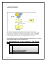
1. Introduction
A growing world wide concern for the conservation of energy has reawakened
interest in ecologically sustainable materials, processes and sources of energy.
Solar photovoltaic is one such system which is highly consistent and reliable
through out the year which is ideally suited for supplying power at remote
locations.
GAIL has good experience of one such solar photovoltaic system installed at
their one of the stations and hence wishes to expand use of solar in their other
stations as well. Similarly it also wishes to establish similar systems to strengthen
the existing stations operation as well.
With this objective, GAIL is proposing to set up environmental friendly Solar
Power Systems for Compressor stations as a mode for back-up supply thereby
reducing use of DG and/or do away with DG sets. The performance of this
location shall be monitored closely with special emphasis on maintenance,
battery life, reliability etc.
With this background two types of Solar PV Systems are proposed.
2. Design Basis
Solar PV Power plants shall be designed considering the following:
1. Sun shine: 5 Peak hours
2. Existing Battery bank should be considered while designing the system.
3. System voltage : 24V dc (nominal)
3. Scope of Work
This job involves by means of the enclosed specification, design, manufacture,
supply, installation, commissioning of the Solar PV Power System with 1 year
warranty period.
The Scope of Work shall include the following,
a. Design, manufacture, supply of Solar PV Power Plant
b. Detailed planning of smooth execution of the project
c. Performance testing of the complete system & warranty of the system for
1 year faultless operation.
d. After-sales service, directly or through local contractual arrangement
e. Risk liability of all personnel associated with the implementation realization
of the project.
Page 1 of 10
4. Operation of the system
The Proposed schematic of the Solar PV Power System is shown above. Solar
Photovoltaic array produces DC electricity directly from the sun light. The Battery
Bank is charged by Solar Array. The charging of Battery Bank is controlled by
Solar Charge Controller to prevent excessive discharge or overcharge.
Interconnecting cables are used between various components such as Solar Modules,
Junction Boxes, Charge Controller and Battery Bank.
5.0 Technical specifications of major components of Solar PV Power
System
1
2
3
4
5
6
7
8
Page 2 of 10
Solar PV modules and array
Module mounting structures for Solar PV Modules
Junction Boxes
Solar Charge Controller
Distribution Boards
Cables and installation accessories
Earthing and lightning protection
Battery & control room– Existing at both locations (Ref page 7)
Solar PV modules and array
Crystalline high power cells shall be used in the Solar Photovoltaic module. Each
Solar module shall consist of 72 Photovoltaic cells redundantly interconnected
and peak power rating shall not be less than 165 W. The bidder offering
single module with highest wattage shall be given preference.
To connect the solar module interconnection cable shall be provided. Photo /
electrical conversion efficiency of SPV module shall be greater than 13.5%.
Module shall be made of high transmissivity glass front surface giving high
encapsulation gain and hot butyl rubber edge sealant for module protection and
mechanical support.
All materials used shall have a proven history of reliable and stable operation in
external applications. It shall perform satisfactorily in relative humidity up to
100% with temperatures between -10 Deg C and +85 Deg C and with stand
gust up to 200km/h from back side of the panel.
Solar module shall be crystalline type, employing lamination technology using
established polymer (EVA) and Tedlar or Polyester laminate.
Offered modules must be IEC 61215 certified and IEC 61730 certified. The
offered modules shall be UL and CE certified and also FM approved for Class 1
Division 2 Group A, B C & D Hazardous locations, considering the proximity
towards inflammable Oil and Gas environment. The bidder shall submit
appropriate certificates.
Other general requirements of PV module
•
•
•
•
•
•
The rated output power of any supplied module shall not vary more than 3-5%
from the average power rating of all modules.
Higher efficiency cells and modules are preferred. Cell level efficiency shall be
over 14.5% and Module Efficiency shall be min 13.5%. Bidder has to prove
and provide the calculations for the module level efficiency when called for
along with details.
The module frame is made of corrosion resistant materials, which is
electrolytically compatible with the structural material used for mounting the
module.
Protective devices against surges at the PV module shall be provided, if
required. Low voltage drop bypass and / or blocking diode(s) may also be
provided, if required.
Module Junction box (weather resistant) shall be designed for long life out
door operation in harsh environment.
A minimum Power Warranty of 25 years shall be given with degradation
of power generated not exceeding 20% over the entire 25 year period
(and 5 years limited warranty of material and workmanship).
Page 3 of 10
•
•
•
•
•
The solar modules shall have suitable encapsulation and sealing
arrangements to protect the silicon cells from the environment. The
arrangement and the material of encapsulation shall be compatible with the
thermal expansion properties of the Silicon cells and the module framing
arrangement/material. The encapsulation arrangement shall ensure complete
moisture proofing for the entire life of the solar modules.
Each module shall have low iron tempered glass front for strength and
superior light transmission. It shall also have tough multi layered polymer
back sheet for environment protection against moisture and provide high
voltage electrical insulation.
The fill factor of modules shall not be less than 0.70 (typical)
Array capacity shall be suitable to the requirement and calculations should be
provided by the bidder. Depending on size of the power plant, number of
modules required shall be worked out accordingly.
Data sheet of the offered module shall be submitted along with the offer
giving details of peak power, peak current, short circuit current, fill factor,
open circuit voltage, peak power voltage etc.
Orientation and Tilt of PV Module
Modules alignment and tilt angle shall be calculated to provide the maximum
annual energy output. This shall be decided based on the location of array
installation.
Module mounting structure
•
•
•
•
The array structure shall be made of hot dip galvanized MS angles of size
not less than 50 mm x 50 mm x 6 mm size. The minimum thickness of
galvanization shall be at least 70 microns. All nuts & bolts shall be made
of very good quality stainless steel. The minimum clearance of the lowest
part of the module structure and the developed ground level shall not be
less than 500 mm. The structure shall have tilt span of 0 to 60 deg in steps
of 5 deg.
Leg assembly of module mounting structure made of different diameter
galvanized tubes may be accepted. The work should be completed with
supply, fitting fixing of clamps, saddles, nut & bolts etc. While quoting the
rate, the bidder may mention the design & type of structure offered. All
nuts & bolts shall be made of very good quality stainless steel.
The structure shall be designed to allow easy replacement of any module
and shall be in line with site requirements.
The structure shall be designed for simple mechanical and electrical
installation. It shall support SPV modules at a given orientation, absorb
and transfer the mechanical loads to the ground properly. There shall be
no requirement of welding or complex machinery at site.
Page 4 of 10
•
The array structure shall be so designed that it will occupy minimum space
without sacrificing the output from SPV panels at the same time it will
withstand wind speed up to maximum 200 km/h. Also it must be
compatible for installations in the corrosive atmospheric conditions
of coastal locations
•
The supplier/manufacturer shall specify installation details of the PV
modules and the support structures with appropriate diagrams and
drawings.
•
The drawings along with detailed design shall be submitted to GAIL for
approval before starting the execution work. The work will be carried out
as per designs approved by GAIL.
•
PCC Array Foundation Base: The legs of the structures made with GI
angles will be fixed and grouted in the PCC foundation columns made with
1:2:4 cement concrete. The minimum clearance of the lowest part of any
module structure shall not be less 500 mm from ground level. While
making foundation design, due consideration shall be given to weight of
module assembly, maximum wind speed of 200 km/hr and seismic factors
for the site.
•
The bidder can visit the site before quoting rate for civil works. After taking
into consideration all aspects of the site, condition of soil etc., the bidder
shall quote for civil works. No extra claim shall be entertained at post
project stage. The foundation design of module structure design shall be
submitted to GAIL for approval. The work will be carried out as per
designs approved by GAIL.
Junction Boxes
The junction boxes shall be flame proof & explosion proof. Also dust, vermin and
waterproof and made of suitable material. The terminals shall be connected to
copper bus bar arrangement of proper sizes. The junction boxes shall have
suitable cable entry points fitted with cable glands of appropriate sizes for both
incoming and out going cables. Suitable markings shall be provided on the bus
bar for easy identification and cable ferrules shall be fitted at the cable
termination points for identification. The junction boxes shall have suitable
arrangement for the following:
• Combine groups of modules into independent charging sub-arrays that
shall be wired to the SCR.
•
Provide a test point for each sub-group for quick fault location.
•
To provide group array isolation.
•
The rating of the JB’s shall be suitable with adequate safety factor to inter
connect the Solar PV array.
Page 5 of 10
Solar Charge Regulator (SCR)
SCR shall have Protection against transient / surge.
SCR shall have Blocking diode to prevent discharge of battery through solar
array during night.
SCR shall have Protection against Over Charging of the battery.
SCR shall disconnect the Load & Protects the battery against Deep
Discharge.
MCBs shall be provided for Array and load.
Built-in cable drop and temperature compensation.
Robust Enclosure.
BATTERY BANK
The existing battery bank available at the station of GAIL will be used in
this system. The batteries available are of Ni-Cd cells. However System
integration will be in the supplier’s scope.
DC Distribution Board (DCDB)
Solar array side breaker and battery side breaker shall be housed in enclosure.
Cables and Accessories
All the cables shall be supplied conforming to IS 1554 / 694 Part 1 of 1988 &
shall be of 650 V/ 1.1 kV grade as per requirement. Only polyethylene copper
cables shall be used. The size of the cables between array interconnections,
array to junction boxes, junction boxes to PCU etc shall be so selected to keep
the voltage drop and losses to the minimum. Suitable length of armored cables of
appropriate grades shall be provided wherever needed.
The bidder shall supply installation accessories, which are required to install and
successfully commission the power plant.
Earthing and lightning protection
Page 6 of 10
Earthing: The array structure of the PV yard shall be grounded properly using
adequate number of earthing kits. All metal casing / shielding of the plant shall be
thoroughly grounded to ensure safety of the power plant.
.
Lightning: The SPV Power Plant shall be provided with lightning & over voltage
protection. The main aim in this protection shall be to reduce the over voltage to
a tolerable value before it reaches the PV or other sub system components. The
source of over voltage can be lightning, atmosphere disturbances etc.
Metal oxide variastors shall be provided inside the Array Junction Boxes. In
addition suitable MOV’s also shall be provided in the Inverter to protect the
inverter from over voltage.
6. Battery room and control room
The bidder shall design suitably the space of the equipment / components
to be installed indoor within the existing Control room & Battery Room. The
bidder shall submit the detailed drawings of layout etc prior to start of work
for approval of GAIL.
7. Bill of Materials
A complete Bill of Materials inclusive of Solar PV Modules, array Junction box,
main junction box, cables, Battery bank, Solar charger, Array mounting structures
etc shall be provided along with the offer. The numbers of each component
proposed for supply shall be clearly specified. The items not listed in BOM but
required for successful installation/commissioning of power plants shall also be
added, as required.
8. Spare parts
Bidder shall keep stock of essential spares at their nearest service center and/or
for 1 year of warranty. However bidder shall list out spare parts required for
power plant. GAIL shall buy essential spares after the warranty period.
9. Installation and commissioning
•
•
The bidder is advised to visit the site before quotation. The site is
approx 100 KM from Mumbai and 150km from Pune. The site is in
remote location and our company shall not be in a position to
provide electricity, water or manpower .The work at the site shall be
carried out through permit system. Only authorized person can work
at site in presence of GAIL representative. The worker inside the
premises has to obey safety procedure.
The bidder is responsible for arranging all the accessories and measuring
instruments required to smoothly commission the power plants.
Page 7 of 10
•
•
The plant shall be commissioned in the presence of GAIL authorized
personnel or its nominated representative.
An acceptance report shall be prepared and signed by all participating
parties.
10. Packing, shipping and marking
The bidder shall be responsible for assuring that all commodities shipped are
properly packed and protected to prevent damage or deterioration during
shipment. Packaging and shipping costs shall be borne by the supplier. Customs
clearance and all costs and actions associated with import duties, taxes and
processing of documents within India are borne by the bidder.
11. Insurance
The bidder shall provide insurance coverage ex-factory until commissioning, and
acceptance for replacement or repair of any part of the consignment due to
damage or loss.
12. After sales & service
The bidder shall give the details of their service center in the state of
Maharashtra (close to Panvel / Mumbai / Pune) and ensure that essential men
and materials are placed to ensure quick and efficient after sales service.
Training and after sales service is an important component of supply. The terms
and conditions for training and after sales supply and service are to be presented
clearly in the proposal and the extent and duration of after sales support clearly
defined. An explanation of preventative maintenance schedule, plan of operation,
scope and implementation of the after sales service is to be defined.
13. Health, Safety & Environment
The successful bidder shall submit the following before starting the installation of
the power plant.
• Safety and Environment policy of the Company
• Emergency Management Plan
14. Delivery of the power plants
The total delivery period shall be 10 weeks from the date of placement of PO.
This includes submission & approval of drawings also.
15. Documentation
Two sets of installation manual / user manual shall be supplied along with the
each power plant. The manual shall include complete system details such as
Page 8 of 10
array lay out, schematic of the system, inverter details, working principle etc.
Step by step maintenance and trouble shooting procedures shall be given in the
manuals.
16 Technical Evaluations
The bidder must clear submit bill of material as 5.10kw (ONE no) as
independent units and must comply with the following otherwise those party shall
be deemed as technically rejected. At any point of time these technical
documents required for evaluation the document sent by E-Mail shall not be
considered for evaluation.
.
•
Each Solar module shall consist of 72 Photovoltaic cells redundantly
interconnected and peak power rating shall not be less than 165 W. Bidders
must submit only manufacture’s catalogue/datasheet to prove the same. No
other documents shall be acceptable for the same.
•
The bidders must mention the model of PV module very clearly in bill of
material and it(the module) must be clearly mentioned in the certificates of
IEC 61215 & IEC 61730 certified to be submitted . The bidder shall submit
appropriate certificates. Also should have the approval for hazardous
condition (FM – Class 1 Division 2 – Group A, B, C & D hazardous locations),
& UL std. approval for electrical fire & safety (class c fire rating) .
•
The Bidder must have ISO 14001 Certification for the facility from where the
SPV cells and modules are manufactured.
•
Manufacturing datasheet/catalogue shall be attached showing that particular
module shall have minimum 12 Year limited power warranty for 90% power
Output & 25 Year limited warranty for 80% power output. Also limited
warranty of 5 years against workmanship and material.
•
A complete Bill of Materials inclusive of Solar PV Modules, array Junction
box, main junction box, cables, Battery bank, Solar charger, Array mounting
structures etc shall be provided along with the offer. Offers not providing the
same shall not be evaluated
•
Offers not providing minimum array capacity of designated rating (Wp) shall
be considered non-responsive and shall not be evaluated.
•
The bidder must mention the provision of sensors & signal conditioning of
various signals as mentioned below with proportional outputs :-
Page 9 of 10
- Battery voltage
- PV voltage
- PV Current
- Battery Current
- Charger Temperature Sensing
- Battery Temperature Sensing
- Remote Alarm facility for various signals
- Energy Monitoring system : Various parameter monitoring & logging
system for Battery Ah, PV AH, Battery Volts, PV volts, Temperature, KWhr
– day basis & history data
- Adjustable Setting of Battery charging algorithm.
- Remote Display facility provision.
- Battery, PV & Load Isolators
- Temp. Controlled forced cooling.
Bidders not providing the data showing above monitoring/Sensor system along
with the offer shall be technically rejected.
Page 10 of 10