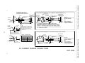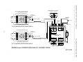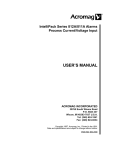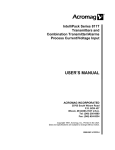
1
Artisan Technology Group is your source for quality new and certified-used/pre-owned equipment • FAST SHIPPING AND DELIVERY • TENS OF THOUSANDS OF IN-STOCK ITEMS • EQUIPMENT DEMOS • HUNDREDS OF MANUFACTURERS SUPPORTED • LEASING/MONTHLY RENTALS • ITAR CERTIFIED SECURE ASSET SOLUTIONS SERVICE CENTER REPAIRS Experienced engineers and technicians on staff at our full-service, in-house repair center WE BUY USED EQUIPMENT Sell your excess, underutilized, and idle used equipment We also offer credit for buy-backs and trade-ins www.artisantg.com/WeBuyEquipment InstraView REMOTE INSPECTION LOOKING FOR MORE INFORMATION? Visit us on the web at www.artisantg.com for more information on price quotations, drivers, technical specifications, manuals, and documentation SM Remotely inspect equipment before purchasing with our interactive website at www.instraview.com Contact us: (888) 88-SOURCE | [email protected] | www.artisantg.com IntelliPack Series 812A/811A Alarms Process Current/Voltage Input USER’S MANUAL ACROMAG INCORPORATED 30765 South Wixom Road P.O. BOX 437 Wixom, MI 48393-7037 U.S.A. Tel: (248) 624-1541 Fax: (248) 624-9234 Copyright 1997, Acromag, Inc., Printed in the USA. Data and specifications are subject to change without notice. 8500-562-K04J008 Artisan Technology Group - Quality Instrumentation ... Guaranteed | (888) 88-SOURCE | www.artisantg.com IntelliPack Series 812A/811A Alarm User’s Manual Dual & Single DC Voltage/Current Inputs ___________________________________________________________________________________________ Safety Summary - Symbols on equipment: ! IMPORTANT SAFETY CONSIDERATIONS Means “Caution, refer to this manual for additional information”. The information contained in this manual is subject to change without notice. Acromag, Inc., makes no warranty of any kind with regard to this material, including, but not limited to, the implied warranties of merchantability and fitness for a particular purpose. Further, Acromag, Inc., assumes no responsibility for any errors that may appear in this manual and makes no commitment to update, or keep current, the information contained in this manual. No part of this manual may be copied or reproduced in any form, without the prior written consent of Acromag, Inc. Table of Contents Page 1.0 INTRODUCTION ………………………..…………….. DESCRIPTION ………………………..………….……. Key IntelliPack 811A/812A Features ……………… ACCESSORY ITEMS …………………………..…….. IntelliPack Configuration Software ...……………… IntelliPack Serial Port Adapter …………………..… IntelliPack Cable………………………….………….. IntelliPack Interface Package…..………………..…. Optional AC Current Sensor ……………………….. 2.0 PREPARATION FOR USE ….……………………….. UNPACKING AND INSPECTION …………………… INSTALLATION ……………………………………….. Mounting ……………………………………………… Electrical Connections ……………………………… 3.0 MODULE CONFIGURATION ……………………….. FIELD CONFIGURATION ……………………………. 4.0 THEORY OF OPERATION ………………………….. 5.0 SERVICE AND REPAIR ……………………………... SERVICE AND REPAIR ASSISTANCE ……………. PRELIMINARY SERVICE PROCEDURE ………….. 6.0 SPECIFICATIONS ……………………………………. MODEL NUMBER DEFINITION……………………… INPUT SPECIFICATIONS.……………………………. RELAY OUTPUT SPECIFICATIONS………..………. DPDT Alarm Relay Specifications ………………… SPDT Alarm Relay Specifications ………………… ENCLOSURE/PHYSICAL SPECIFICATIONS..…….. APPROVALS …………………………….…………….. ENVIRONMENTAL SPECIFICATIONS.…………….. FIELD CONFIGURATION & CONTROLS…………… HOST COMPUTER COMMUNICATION…………….. SOFTWARE CONFIGURATION..……………………. List of Drawings 1.0 INTRODUCTION These instructions cover hardware functionality of the alarm models listed in Table 1. Supplementary sheets are attached for units with special options or features. Table 1: Models Covered in This Manual -Factory Series/ -Options/Output/ Input/Type Enclosure/Approvals1 Configuration2 812A -0200 -C 811A -0100 -C 811A -0200 -C 2 2 3 3 3 4 4 4 4 4 4 4 5 5 6 6 7 7 7 7 7 7 7 8 8 8 9 9 9 9 10 10 Notes (Table 1): 1. Agency approvals include CE, UL Listed, and cUL Listed. 2. Include the “-C” suffix for optional factory configuration. See Factory Configuration Order Form 8500-584 for this model. Otherwise, no suffix is required for standard configuration. Module programming, alarm operation, and use of the Configuration Software is covered in the IntelliPack Alarm Configuration Manual (8500-563). DESCRIPTION Series 811A/812A Alarms are members of the popular Acromag IntelliPack Alarm & Transmitter family and these models accept DC current, DC voltage, and AC current (using an external sensor) inputs. Output options are two Single-Pole Double-Throw (SPDT) electro-mechanical relays, or one DoublePole Double-Throw (DPDT) electro-mechanical relay. All units contain an advanced technology microcontroller with integrated downloadable flash memory and EEPROM for non-volatile program, configuration, calibration, and parameter data storage. Units are fully configurable via our user-friendly Windows 95 or NT configuration program. In-field reconfiguration is also possible with module push buttons and status LED’s. Once configured, these modules may operate independent of the host computer for true embedded monitoring and control. Page Simplified Schematic & Contact Protection (4501-625)... Functional Block Diagram (4501-695)….………………… Computer to IntelliPack Connections (4501-635).………. Electrical Connections (4501-632).……………………….. AC Sensor Connections (4501-633).…….……………….. Interposing Relay Connections (4501-634).……………… Enclosure Dimensions (4501-631).……………………….. It is very important for the user to consider the possible adverse effects of power, wiring, component, sensor, or software failures in designing any type of control or monitoring system. This is especially important where economic property loss or human life is involved. It is important that the user employ satisfactory overall system design. It is agreed between the Buyer and Acromag, that this is the Buyer's responsibility. Modules may be field connected for either DC Voltage or process current input signals. Wide range bipolar DC voltage inputs to ±100VDC are possible. The 811A has a single input, while the 812A provides two inputs. On-board excitation is provided at each input to facilitate two-wire transmitter hookup. Each relay has a yellow LED at the front of the module that provides a visual indication of the high or low alarm condition. Additionally, a green “Run” and yellow “Status” LED provide local feedback of operating mode, field configuration status, and system diagnostics. Front panel push buttons are available to reset latching alarms and to facilitate field configuration. 12 13 14 15 16 17 18 Windows 95 & NT are registered trademarks of Microsoft Corp. -2Artisan Technology Group - Quality Instrumentation ... Guaranteed | (888) 88-SOURCE | www.artisantg.com IntelliPack Series 812A/811A Alarm User's Manual Dual & Single DC Voltage/Current Inputs ___________________________________________________________________________________________ The module uses a high-resolution, low-noise, Sigma-Delta Analog-to-Digital Converter (Σ-∆ ADC) to accurately convert the input signal into a digitized value. User-defined alarm setpoints are compared to this value and used to control the built-in alarm relay(s). Each relay may have high or low setpoints plus deadband. Both the alarm setpoints and deadband may be adjusted over the full input range of the unit. Relay actuation is user-selected for failsafe or non-failsafe operation. Relays may be configured as latching, in which case a push button reset is required to reset the latch (this may also be accomplished via software control). Additionally, a programmed relay time delay may be applied to filter transients and minimize nuisance alarms. Key IntelliPack 811A/812A Features…continued • • • • Wide alarm functionality and convenient reprogrammability makes these alarms extremely powerful and flexible over a broad range of applications. These models may be configured as limit alarms, window alarms, on/off controllers, deviation alarms (dual input models), peak detect alarms, or rate-of-change alarms. Other functions are possible--please consult the factory. • • An optional AC current sensor (Acromag Model 5020-350) is used in conjunction with the DC current input circuit of the 811/812A to implement an AC current alarm for inputs up to 20A rms. The optional AC current sensor is itself an isolated, accurate, toroidal instrument transformer, that outputs a safe, low-level DC milliamp signal to the input of the alarm. As an isolated device, it may also be used to facilitate input-to-input isolation on dual input models. See “AC Current Sensor” section for more information. • • • All IntelliPack modules are designed to withstand harsh industrial environments. They feature RFI, EMI, ESD, EFT and surge protection, low temperature drift, wide ambient temperature operation, and isolation from input, to power and relay contacts. As a wide-range DC-powered device, the unit may be powered from DC power networks incorporating battery back up. Additionally, the input power terminal is diode-coupled, providing reverse polarity protection. This allows the unit to be connected to redundant power supplies, or several units to safely share a single DC supply. • • • Units are DIN rail mounted and removable terminal blocks facilitate ease of installation and replacement, without having to remove wiring. Alarm relay and power wiring are inserted at one side of the unit, while input wiring is inserted at the other side. Connectors are industry standard screw clamp type and accept a wide range of wire sizes. • • The safe, compact, rugged, reconfigurable, and reliable design of this alarm makes it an ideal choice for control room and field applications. Custom alarm configurations are also available (please consult the factory). • • Key IntelliPack 811A/812A Features • Agency Approvals - CE, UL Listed, & cUL Listed. • Windows Configuration - Fully reconfigurable via our user friendly Windows 95 or NT Configuration Program. • Nonvolatile Reprogrammable Memory - This module has an advanced technology microcontroller with integrated, non-volatile, downloadable flash memory and EEPROM. • Convenient Field Reprogrammability - The unit includes push-button reconfiguration of key alarm functions in combination with LED indicators to facilitate in-field changes without having to connect a host computer. • • Wide Alarm Functionality - The unit may be programmed for a wide range of alarm types including limit, window, on/off controller, deviation (dual input models), peak detection, and rate-of-change alarms. Other functions are possible (please consult the factory). Flexible DC Current or Voltage Inputs - Accepts process current (0-24mA), or wide range voltage inputs to ±100VDC. Optional AC Current Input - An optional AC current sensor can be purchased separately to support AC current inputs. Wide Ambient Operation - The unit is designed for operation over wide ambient temperatures. Convenient Input Excitation Supply - Each input includes an excitation supply for operation with two-wire transmitters. High-Power SPDT or DPDT Relays - The module includes either one Double-Pole-Double-Throw (DPDT) electromechanical relay, or two Single-Pole-Double-Throw (SPDT) electromechanical relays, for switching voltages to 230VAC at currents to 5A. Fully Isolated - Input(s), power, and relay contacts are all isolated from each other. Dual input units share a common and do not provide input-to-input isolation. Self-Diagnostics - Built-in routines operate upon power-up for reliable service, easy maintenance, and troubleshooting. LED Indicators - A green LED indicates power. A yellow status LED turns on if input signal is out of calibrated range. A yellow alarm LED indicates when a relay is in alarm. These LED’s have other functions in field program mode. Wide-Range DC-Powered - This device receives power over a wide DC supply range and the power terminal is diode-coupled. This makes the alarm useful for systems with redundant supplies, and/or battery backup power. Hardened For Harsh Environments - The unit will operate reliably in harsh industrial environments and includes protection from RFI, EMI, ESD, Surges, and EFT. Convenient Mounting, Removal, & Replacement - DINRail mounting and plug-in type terminal blocks for input, power, and relay contact wiring makes replacement and removal easy. High-Resolution Precise A/D Conversion - Alarms include an advanced, high-resolution, low noise, Sigma-Delta Analog to Digital Converter (Σ-∆ ADC) for high accuracy and reliability. Individual Relay Functionality - Each relay of dual relay units may be programmed for different functions. Failsafe or Non-Failsafe Relay Operation - The unit may be configured for failsafe or non-failsafe relay operation. Configurable Setpoint With Deadband - Programmable deadband is associated with each setpoint to eliminate relay “chatter” and prolong contact life. Configurable Latching or Momentary Alarms - These alarms may be configured for automatic alarm reset, or latching alarm with manual push-button or software reset. Configurable Relay Time Delay Filters Transients Useful for increased noise immunity and to filter transients. ACCESSORY ITEMS The following IntelliPack accessories are available from Acromag. Acromag also offers other standard and custom alarm and transmitter types to serve a wide range of applications (please consult the factory). -3Artisan Technology Group - Quality Instrumentation ... Guaranteed | (888) 88-SOURCE | www.artisantg.com IntelliPack Series 812A/811A Alarm User's Manual Dual & Single DC Voltage/Current Inputs ___________________________________________________________________________________________ The output wires of this sensor are polarized with red as (+) plus and black as (-) minus. Normally these output wires are attached to one end of a user supplied cable while the other end connects to the IntelliPack’s process current input terminals. IntelliPack Configuration Software (Model 5030-881) IntelliPack alarms and transmitters are configured using this user-friendly Windows 95 or NT Configuration Program. This software also includes the IntelliPack Alarm Configuration Manual (8500-563) and IntelliPack Transmitter Configuration Manual (8500-570). These manuals describe software operation and various alarm and transmitter functions in detail. All alarm functions are programmable and downloadable to the alarm modules via this software. Non-volatile memory provides program, configuration, and data storage within the IntelliPack. Input Burden: A function of the wire gauge resistance used for primary turns (the current carrying wire being monitored). AC Current Sensor to Transmitter Wiring Distance: 400 feet maximum for 18 gauge wire. Other wire gauges can be used as long as the resistance of both wires is less than 5Ω. Input Overload: The AC current sensor will withstand overload conditions as follows: • 20 times full scale for 0.01 seconds. • 10 times full scale for 0.1 seconds. • 5 times full scale for 1.0 second. IntelliPack Serial Port Adapter (Model 5030-913) This adapter serves as an isolated interface converter between the EIA232 serial port of the host computer and the Serial Peripheral Interface (SPI) port of the IntelliPack module. It is used in conjunction with the Acromag IntelliPack Configuration Software to program and configure the modules. This adapter requires no user adjustment, no external power, and operates transparent to the user. It receives its power from the IntelliPack module. The adapter has a DB9S connector that mates to the common DB9P serial port connector of a host computer. The adapter also has a 6-wire RJ11 phone jack to connect to the IntelliPack alarm module via a separate interconnecting cable (described below). Refer to Drawing 4501-635 for computer to IntelliPack connection details. 2.0 PREPARATION FOR USE UNPACKING AND INSPECTION Upon receipt of this product, inspect the shipping carton for evidence of mishandling during transit. If the shipping carton is badly damaged or water stained, request that the carrier's agent be present when the carton is opened. If the carrier's agent is absent when the carton is opened and the contents of the carton are damaged, keep the carton and packing material for the agent's inspection. For repairs to a product damaged in shipment, refer to the Acromag Service Policy to obtain return instructions. It is suggested that salvageable shipping cartons and packing material be saved for future use in the event the product must be shipped. IntelliPack Cable (Model 5030-902) This 6-wire cable is used to connect the SPI port of the IntelliPack Serial Port Adapter to the IntelliPack. This cable carries the SPI data and clock signals, reset signal, and +5V power and ground signals. The cable is 7 feet long and has a 6wire RJ11 plug at both ends which snap into jacks on the Serial Port Adapter and the IntelliPack module. This module is physically protected with packing material and electrically protected with an anti-static bag during shipment. However, it is recommended that the module be visually inspected for evidence of mishandling prior to applying power. IntelliPack Software Interface Package (Model 800C-SIP) The IntelliPack Interface Package combines the Configuration Software (5030-881), Alarm Configuration Manual (8500-563), Transmitter Configuration Manual (8500-570), Serial Port Adapter (5030-913), and Cable (5030-902), into a complete kit for interfacing with IntelliPack Alarms and Transmitters. This circuit utilizes static sensitive components and should only be handled at a static-safe workstation. AC Current Sensor (Model 5020-350) This optional sensor is an accurate toroidal instrument transformer used to convert a sinusoidal 50-60Hz AC current signal into a low level DC milliampere signal of 0 to 11.17mA. The input AC current range is a simple function of the number of turns placed through the toroid as shown in Table 2. This sensor is isolated and requires no calibration or adjustment. When used with an IntelliPack module, it provides redundant input isolation and may facilitate input-to-input isolation on dual input units. INSTALLATION The alarm module is packaged in a general purpose plastic enclosure. Use an auxiliary enclosure to protect the unit in unfavorable environments or vulnerable locations, or to maintain conformance to applicable safety standards. Stay within the specified operating temperature range for best performance. As shipped from the factory, the unit is factory calibrated for all valid input ranges and has the default configuration shown in Table 3: Table 2: AC Current Sensor Turns & Range AC Current Primary Sensor Output Input Range Turns (Red/Black Wires) 0 to 20A AC 1 0 to 11.17mA DC 0 to 10A AC 2 “ 0 to 5A AC 4 “ 0 to 2A AC 10 “ 0 to 1A AC 20 “ WARNING: Applicable IEC Safety Standards may require that this device be mounted within an approved metal enclosure or sub-system, particularly for applications with voltages greater than or equal to 75VDC or 50VAC. -4Artisan Technology Group - Quality Instrumentation ... Guaranteed | (888) 88-SOURCE | www.artisantg.com IntelliPack Series 812A/811A Alarm User's Manual Dual & Single DC Voltage/Current Inputs ___________________________________________________________________________________________ Table 3: 811A/812A Default Factory Configuration CONFIGURATION PARAMETER INPUT 1 INPUT 2 Input Range 0-22mA 0-22mA Alarm Type Limit Limit ALARM 1 ALARM 2 Mode High Limit Low limit Setpoint 20mA 4mA Deadband 1% (0.16mA) 1% (0.16mA) RELAY 1 RELAY 2 Time Delay 100ms 100ms Operating Mode Failsafe Failsafe Reset Auto (Momentary) Auto (Momentary) CAUTION: Risk of Electric Shock - More than one disconnect switch may be required to de-energize the equipment before servicing. 1. Power: Refer to Electrical Connections Drawing 4501-632. Variations in power supply voltage within rated limits has negligible effect on module accuracy. For supply connections, use No. 14 AWG wires rated for at least 75°C. The power terminal is diode-coupled for reverse polarity protection. 2. DC Voltage/Current Inputs (Without AC Current Sensor): Connect input(s) per Drawing 4501-632. Observe proper polarity (see label for input type). An excitation supply is provided at the input terminals for two-wire transmitters. Dual input models do not provide input-to-input isolation. Notes (Table 3): Shaded entries do not apply to Model 811A-0100 units. 3. AC Current Input (Optional): Refer to Drawing 4501-633 to connect the optional AC current sensor. This sensor is typically mounted near the AC current measured and will transmit a low level DC milliampere signal to the module. This allows the module to be mounted remote from the AC signal and sensor, and connected using small gauge wire. The sensor output (Red/Black) wires can be shorted, opencircuited, or removed from the alarm input terminals, without hazard to personnel or to the sensor. As an isolated device, this sensor may be used to facilitate input-to-input isolation on dual input units. Your application may differ from the default configuration and will require the alarm to be reconfigured to suit your needs. This is accomplished with Acromag’s user-friendly Windows 95/NT Configuration Program & Serial Port Adapter. Configuration is normally done prior to field installation since field configurability via the module’s push-buttons is generally limited to setpoint and deadband adjustments where applicable. See the Alarm Configuration Manual 8500-563 for instructions. Mounting: Refer to the Enclosure Dimensions Drawing 4501-631 for alarm mounting and clearance dimensions. AC Current Sensor: Per Table 2 on Page 4, loop the required number of turns through the toroid for the full-scale current range required by your application. Use the cable tie provided with the sensor to mechanically secure it. DIN Rail Mounting: This module can be mounted on "T" type DIN rails. Use suitable fastening hardware to secure the DIN rail to the mounting surface. Units may be mounted side-by-side on 1-inch centers for limited space applications. DANGER: If the AC current sensor is used with an AC Current Transformer (C.T.), disconnect power from the C.T., or short the output of the C.T., before removing the wire going through the AC current sensor. If this is not done, an open circuited C.T. will generate hazardous high voltages and possible C.T. damage. "T" Rail (35mm), Type EN50022: To attach a module to this style of DIN rail, angle the top of the unit towards the rail and locate the top groove of the adapter over the upper lip of the rail. Firmly push the unit towards the rail until it snaps solidly into place. To remove a module, first separate the input terminal block(s) from the bottom side of the module to create clearance to the DIN mounting area. Next, insert a screwdriver into the lower arm of the DIN rail connector and use it as a lever to force the connector down until the unit disengages from the rail. 4. Output Contacts: Wire relay contacts as shown in Electrical Connections Drawing 4501-632. See the “Alarm Relay Specifications” for power capacity. If necessary, an interposing relay can be used to switch higher currents as shown in Interposing Relay Connection Drawing 4501-634. Electrical Connections Electromechanical Relay Contact Protection: To maximize relay life with inductive loads, external protection is required. For DC inductive loads, place a diode across the load (1N4006 or equivalent) with cathode to (+) and anode to (-). For AC inductive loads, place a Metal Oxide Varistor (MOV) across the load. See Relay Contact Protection Drawing 4501-625 for details. Terminals can accommodate wire from 14-24 AWG (stranded or solid copper). Strip back wire insulation 1/4-inch on each lead before installing into the terminal block. Input wiring may be shielded or unshielded twisted pair. Since common mode voltages can exist on signal wiring, adequate wire insulation should be used and proper wiring practices followed. It is recommended that alarm contacts and power wiring be separated from input signal wiring for safety and low noise pickup. Input, power, and relay terminals are plug-in type and can be easily removed to facilitate module removal or replacement without removing individual wires. Be sure to remove power and/or disable the load before unplugging the terminals to uninstall the module, or before attempting service. All connections must be made with power removed. IMPORTANT: Noise and/or jitter on the input signal has the effect of reducing (narrowing) the instrument’s deadband and may produce contact chatter. The long term effect of this will reduce the life of mechanical relays. To reduce this undesired effect, you should increase the effective deadband. -5Artisan Technology Group - Quality Instrumentation ... Guaranteed | (888) 88-SOURCE | www.artisantg.com IntelliPack Series 812A/811A Alarm User's Manual Dual & Single DC Voltage/Current Inputs ___________________________________________________________________________________________ 5. Grounding: See Electrical Connections Drawing 4501-632. The module housing is plastic and does not require an earth ground connection. However, there are mounting positions on the input terminals to connect a cable shield, plus earth ground. These connections are isolated from the input circuit and are recommended to minimize noise and help protect the unit from damaging input transients. General Field Programming Procedure…continued Table 4: Relay Config Parameter 1 Per Alarm Function ALARM FUNCTION PARAMETER 1 Limit Alarm High or Low Setpoint Value Window Alarm High Setpoint Value On/Off Controller Controller “On” Setpoint Value Deviation Alarm Set the Deviation Amount (Use (Both Inputs Required) Proper Polarity between inputs) Peak/Valley Detector Peak/Valley Detect Start Value Rate-of-Change Alarm Rate-Of-Change Threshold WARNING: For compliance to applicable safety and performance standards, the use of shielded cable is recommended as shown in Drawing 4501-632. Further, the application of earth ground must be in place as shown in Drawing 4501-632. Failure to adhere to sound wiring and grounding practices may compromise safety & performance. 5. Press the “SET” push button to accept the relay 1 parameter indicated in Table 4. Note that every time the “SET” button is pressed, the yellow “Status” LED will flash once and the value at the input(s) will be captured. 6. Press the “MODE” push button once. The relay 1 LED should start flashing (see Table 6). The unit is ready to accept the second parameter for the relay shown in Table 5: 7. Adjust the input source(s) to the desired level. 8. Press the “SET” button to accept the parameter noted in Table 5 for your alarm function. The module will use the difference between the two programmed parameter values to calculate deadband where applicable. 3.0 MODULE CONFIGURATION The alarm module needs to be configured for your application. Alarm configuration is done using Acromag’s Windows 95 or NT Configuration Program and the IntelliPack Serial Port Adapter. Configuration details are covered in Alarm Configuration Manual 8500-563. Limited field configuration via the module’s push-buttons and LED’s is covered below. Table 5: Relay Config Parameter 2 Per Alarm Function ALARM FUNCTION PARAMETER 2 Limit Alarm Setpoint Dropout Value Window Alarm Low Setpoint Value On/Off Controller Controller “Off” Setpoint Value Deviation Alarm (Both Deviation Dropout Value Inputs Required) Peak/Valley Detector Peak or Valley Dropout Value Rate-of-Change Dropout Rate for Rate-of-Change FIELD CONFIGURATION This program mode allows adjustment to key alarm parameters in the field, without having to connect a host computer. Field reconfigurability is accomplished via the alarm module’s “MODE” & “SET” push buttons and the alarm LED’s (see Drawing 4501-631). Field reconfiguration via these controls will vary depending on the alarm function (see Table 6). Equipment Required • An accurate input source (voltage or current) adjustable over the range required for alarm setpoint and dropout/deadband. Two input sources are required for deviation alarms. Note: For best results, the input source(s) must be accurate beyond the required specifications. For voltage inputs, use a voltage source with an output impedance of 100Ω or less. 9. If two relays are being programmed, Press the “MODE” push button again to complete the first relay program cycle and repeat the above procedure (steps 4-8) to configure parameters for relay 2 (relay 2 LED will light, “Run” LED will still be off). You may skip relay 2 by pressing “MODE” again as in step 10. 10. After configuring relay 1, and relay 2 (where applicable), press the “MODE” push button again to complete the program sequence and return to run mode. The green “Run” LED will turn ON. This indicates that the unit has returned to the operating mode and the yellow relay LED’s will now reflect actual alarm status per your application. General Field Programming Procedure The following procedure uses the corresponding relay LED indicators (constant ON or FLASHING) to indicate which relay parameters (relay 1 or 2) are being modified (see Table 6). CAUTION: To avoid damage to the unit, do not insert sharp or oversized objects into the push-button switch openings. When depressing the push-buttons, use a blunt tipped object and apply pressure gradually until you feel or hear the tactile response. Notes (Field Program Procedure): 1. 1. Connect a precision voltage or current source to the input, as required (refer to Electrical Connections Drawing 4501-632). For deviation alarms, two input sources are required. 2. Apply power and wait for the module’s green “Run” LED to light (continuous ON). 3. Press and hold the “MODE” push button until the “Run” LED goes out, and the relay 1 LED lights (see Table 6). In this mode, the unit is ready to accept an input for parameter 1 of relay 1 per Table 4 below. If you do not wish to change this parameter, skip to step 6. 4. Adjust the input source(s) to the relay parameter 1 level shown in Table 4 according to your alarm function (deviation alarms require an adjustment at both inputs). During field configuration of dual relay models, the relay LED will be ON or FLASHING, corresponding to the relay being programmed and the parameter being adjusted as in Table 6: Table 6: Field Configuration Relay LED Mode Indication ALARM RELAY 1 or 2 LED FUNCTION ON FLASHING Limit HI/LO Setpoint HI/LO Dropout Window High Setpoint Low Setpoint ON/OFF Controller ON Setpoint OFF Setpoint Deviation Deviation Dropout Peak/Valley Detect P/V Detect Start P/V Dropout Rate-Of-Change ROC Threshold ROC Dropout -6Artisan Technology Group - Quality Instrumentation ... Guaranteed | (888) 88-SOURCE | www.artisantg.com IntelliPack Series 812A/811A Alarm User's Manual Dual & Single DC Voltage/Current Inputs ___________________________________________________________________________________________ If the diagnostics complete successfully, the “Run” LED will stop flashing after two seconds and then remain ON. This indicates that the unit is operating normally. If the “Run” LED continues to flash, then this is indicative of a problem. In this case, use the Acromag IntelliPack Configuration Software to reconfigure the module and this will usually cure the problem. If the diagnostics indicate a problem via a continuously flashing green LED, or if other evidence points to a problem with the unit, an effective and convenient fault diagnosis method is to exchange the questionable module with a known good unit. Notes (Field Program Procedure)…continued: 2. If the alarm is in configuration mode and no push buttons are pressed after 2 minutes, then the alarm will return to normal operating mode, the green “Run” LED will light, and no changes will be made to the previously configured values. 3. Latching alarms require a push button reset to exit the alarm state (this may also be accomplished under software control). 4. Deadband and latching relays have no application with respect to on/off controller functionality. 5. Rate-of-change units (volts/second) are software configured only and not configured via the module’s push-buttons. 6. Note that alarm operating functions may be selected on a per relay basis. For example, relay 1 could function as a “limit alarm” monitoring input 1, while relay 2 (if present) functions as an “on/off controller” monitoring input 2. Note that some functions require the use of both inputs of dual input models. The IntelliPack Serial Port Adapter also contains a red LED visible at the small opening in the enclosure to the right of the RJ11 receptacle. If this LED is OFF or Flashing, then a communication interface problem exists. Note that the adapter receives its power from the IntelliPack module. A constant ON LED indicates a properly working and powered serial interface adapter. 4.0 THEORY OF OPERATION Acromag’s Application Engineers can provide further technical assistance if required. When needed, complete repair services are available from Acromag. Refer to Drawing 4501-625 to gain a better understanding of the circuit. These alarms will pre-filter a signal and convert the signal to a scaled voltage--either through a voltage divider circuit (voltage inputs), or a current sink resistor (current inputs). An A/D converter stage then applies appropriate gain to the signal, digitally filters it, and performs analog-to-digital conversion. The digital signal is then transmitted serially to a microcontroller. The microcontroller compares the signal value to the limit value according to the alarm type, and completes all necessary alarm functions per its embedded program. Configuration and calibration parameters are stored in non-volatile memory within the microprocessor. A wide input switching regulator (isolated flyback mode) provides isolated 5V power to the circuit, plus a 15V excitation supply. 6.0 SPECIFICATIONS 812A-0200, Dual I/V Input, Dual SPDT Relay 811A-0200, Single I/V Input, Dual SPDT Relay 811A-0100, Single I/V Input, Single DPDT Relay General: The IntelliPack 811A and 812A are DC-powered alarms which condition DC current, DC voltage, and AC current (using an external sensor), and provide either two Single-Pole Double-Throw (SPDT) electromechanical alarm relays, or one Double-Pole Double-Throw (DPDT) electromechanical alarm relay. Isolation is supplied between the sensor input, the relay contacts, and power. This alarm is DIN-rail mounted. 5.0 SERVICE AND REPAIR The unit is configured and calibrated using our user-friendly Window 95 or NT IntelliPack Configuration Program. Push-buttons on the module allow field adjustment of setpoint and deadband (where applicable). All calibration and configuration information is stored in non-volatile reprogrammable memory in the module. CAUTION: Risk of Electric Shock - More than one disconnect switch may be required to de-energize the equipment before servicing. SERVICE AND REPAIR ASSISTANCE This module contains solid-state components and requires no maintenance, except for periodic cleaning and configuration parameter verification (setpoint, deadband, etc). Since Surface Mount Technology (SMT) boards are generally difficult to repair, it is highly recommended that a non-functioning module be returned to Acromag for repair. The board may be damaged unless special SMT repair and service tools are used. Further, Acromag has automated test equipment that thoroughly checks and calibrates the performance of each module. Please refer to Acromag’s Service Policy Bulletin or contact Acromag for complete details on how to obtain service parts and repair. MODEL NUMBER DEFINITION Alarms are color coded with a yellow label. The prefix “8” denotes the IntelliPack Series 800, while the “A” suffix specifies that outputs are alarm contacts. 812A: Monitors two DC voltage or current inputs, or AC current inputs (using an external sensor). 811A: Monitors a single DC voltage or current input, or AC current input (using external sensor). PRELIMINARY SERVICE PROCEDURE -0x00: Numbers in this model suffix represent the following options, respectively: Before beginning repair, be sure that all installation and configuration procedures have been followed. The unit routinely performs internal diagnostics following power-up or reset. During this period, all LED’s will turn ON momentarily, and the green “Run” LED flashes. Options = 0: None (reserved for future use); Output = 1: One DPDT relay (described subsequently); Output = 2: Two SPDT relays (described subsequently); Enclosure = 0: DIN rail mount (described subsequently); Approvals = 0: Pending (please consult the factory). -7Artisan Technology Group - Quality Instrumentation ... Guaranteed | (888) 88-SOURCE | www.artisantg.com IntelliPack Series 812A/811A Alarm User's Manual Dual & Single DC Voltage/Current Inputs ___________________________________________________________________________________________ Noise Rejection (Common Mode): Better than 100dB @ 60Hz, typical with 100Ω input unbalance (24.9Ω for process currents). Analog to Digital Converter (A/D): A 16-bit Σ-∆ converter, Analog Devices AD7714AR-5. Input Conversion Rate: 10 conversions per channel per second (dual input models); 20 conversions per second (single input models). Input bias current: ±10nA maximum, excluding excitation current of process current inputs. Input Excitation Supply: +15V DC typical, current limited to approximately 24mA, one per input. For use with two-wire process current transmitters. INPUT SPECIFICATIONS Unit must be wired and configured for the intended input type and range (see Installation Section for details). The following paragraphs summarize this model’s input types, ranges, and applicable specifications. DC (Process) Current: 0 to 22mA DC & 0-5mA DC. A precision 24.9Ω current sink resistor converts the input current to a voltage that is processed by the A/D converter. An optional external sensor is required to monitor AC current signals (Acromag Model 5020-350). This sensor generates a DC milliampere signal of 0 to 11.17mA for the module (see Table 2 for scaling to AC current). This module also provides one excitation supply per input (15VDC @24mA) for use with 2wire transmitters. Current Input Reference Test Conditions: 4 to 20mA current input using the on-board excitation supply; Ambient = 25°C; Power Supply = 24V DC; Relay Time Delay = 100ms. Input Overvoltage Protection: Bipolar Transient Voltage Suppressers (TVS), 7.6V clamp level typical. RELAY OUTPUT SPECIFICATIONS DPDT ALARM OUTPUT (-x1xx): This model contains a single DPDT electromechanical relay comprised of two, high reliability, Form C (Normally Open and Normally Closed) contacts. The DPDT relay option is only available on single input models (811A). DC Voltage (100:1 Input Divider): User-configurable for the following bipolar voltage ranges: ±50 to ±100V; ±25 to ±50V; ±12 to ±25V; ±6 to ±12V; ±3 to ±6V; & ±1 to ±3V. Input Impedance: 500KΩ. Voltage Input Reference Test Conditions: -10 to 10V DC Input; Ambient = 25°C; Power Supply = 24VDC; Relay Alarm Delay = 100ms. Input Overvoltage Protection: Bipolar Transient Voltage Suppressers (TVS), 135V clamp level typical. DPDT Alarm Relay Specifications: Electrical Life - CSA Ratings: 25VDC, 5A, 105 operations, resistive. 48VDC, 0.8A, 105 operations, resistive. 240VDC, 0.1A, 105 operations, resistive. 120/240VAC, 5A, 3x10⁴ operations, resistive. Note: To control a higher amperage device, such as a pump, an interposing relay may be used (see Interposing Relay Connections Drawing 4501-634). Contact Material: Silver-Nickel (AgNi 90/10). Initial Dielectric Strength: Between open contacts: 1000VAC rms (1 minute). Expected Mechanical Life: 30 million operations. Note: External relay contact protection is required for use with inductive loads (see Relay Contact Protection Drawing 4501-625). Failure to use adequate protection may reduce contact life or damage the unit. Relay Response (No Relay Time Delay): Relay contacts will switch within 150ms for an input step change from 10% of span on one side of an alarm point to 5% of span on the other side of the alarm point. General Specifications Accuracy: Better than ±0.05% of input span, typical. Accuracy Versus Temperature: Better than ±0.005% of input span per °C or ±1uV, whichever is greater. Resolution: See Table 7. Table 7: A/D Resolution Per Nominal Input Range Gain Range A/D Resolution 2 0-22mA, 0-24mA Typ 757nA/LSB 8 0-5mA, 0-6mA Typ 189nA/LSB 1 3770uV/LSB ±50 to ±100V 2 1880uV/LSB ±25 to ±50V 4 942uV/LSB ±12 to ±25V 8 471uV/LSB ± 6 to ±12V 236uV/LSB 16 ± 3 to ± 6V 118uV/LSB 32 ± 1 to ± 3V 64, 128 Not Used NA SPDT ALARM OUTPUT (-x2xx): This model contains two independent electromechanical relays. Each relay contains high reliability, Form C (Normally Open and Normally Closed) SPDT contacts. One relay is assigned to each input of dual input models (812A); or both relays to the same input on single input models (811A). Each relay may have any alarm operating function assigned to it. Response Time: Less than 100ms typical to 98% of final value for a step change in input. Note a software configurable delay can be implemented for filtering transients and this will increase the response time. Input Filter: Normal mode filtering, plus digital filtering optimized and fixed per input range within the A/D. Input Bandwidth: Alarm contacts will track an input square wave to approximately 3.5Hz. A relay time delay can be implemented for filtering transients and this will lower the relative bandwidth. Noise Rejection (Normal Mode): Better than 40dB @ 60Hz, typical with 100Ω input unbalance (24.9Ω for process currents). SPDT Alarm Relay Specifications: Electrical Life - CSA Ratings: 25VDC, 5A, 105 operations, resistive. 48VDC, 0.8A, 105 operations, resistive. 240VDC, 0.1A, 105 operations, resistive. 120VAC/240VAC, 5A, 3x10⁴ operations, resistive. Note: To control a higher amperage device, such as a pump, an interposing relay may be used (see Interposing Relay Connections Drawing 4501-634). Contact Material: Silver-cadmium oxide (AgCdO). Initial Dielectric Strength: Between open contacts: 1000VAC rms. -8Artisan Technology Group - Quality Instrumentation ... Guaranteed | (888) 88-SOURCE | www.artisantg.com IntelliPack Series 812A/811A Alarm User's Manual Dual & Single DC Voltage/Current Inputs ___________________________________________________________________________________________ Expected Mechanical Life: 20 million operations. Note: External contact protection is required for use with inductive loads (see Contact Protection Drawing 4501-625). Failure to use adequate protection may reduce contact life or damage the unit. Relay Response (No Relay Time Delay): Relay contacts will switch within 150ms for an input step change from 10% of span on one side of an alarm point to 5% of span on the other side of the alarm point. Table 8: Supply Current Versus Voltage Supply Maximum Supply Current Voltage 812A-0200 811A-0200 811A-0100 10V 250mA 170mA 160mA 12V 195mA 140mA 130mA 15V 155mA 110mA 100mA 24V 110mA 70mA 65mA 36V 100mA 55mA 55mA Note: Disconnecting the Serial Port Adapter and/or unloading the optional excitation supplies will reduce the supply current consumption considerably. ENCLOSURE/PHYSICAL SPECIFICATIONS IMPORTANT – External Fuse: If unit is powered from a supply capable of delivering more than 1A to the unit, it is recommended that this current be limited via a high surge tolerant fuse rated for a maximum current of 1A or less (for example, see Bel Fuse MJS1). See Enclosure Dimensions Drawing 4501-631 for details. Units are packaged in a general purpose plastic enclosure with an integrated DIN rail mount for high density mounting (approximately 1” wide per unit). Dimensions: 1.05” wide x 4.68” high x 4.35” deep. DIN Rail Mounting (-xx0x): DIN rail mount, Type EN50022; “T” rail (35mm). Connectors: Removable plug-in type terminal blocks; Current/ Voltage Ratings: 15A / 300V; Wire Range: AWG #14-24 (stranded or solid copper); Separate terminal blocks provided for power, input(s), & relay contacts. For supply connections, use No. 14 AWG wires rated for at least 75°C. Case Material: Self-extinguishing NYLON type 6.6 polyamide thermoplastic UL94 V-2, color beige; general purpose NEMA Type 1 enclosure. Printed Circuit Boards: Military grade FR-4 epoxy glass. Shipping Weight: 1 pound (0.45 Kg) packed. Power Supply Effect: DC Volts: Less than ±0.001% of input span change per volt DC, for rated power supply variations. 60/120 Hz Ripple: Less than 0.01% of input span per volt peak-to-peak of power supply ripple. Isolation: Input, relay contacts, and power are isolated from each other for common-mode voltages up to 250VAC, or 354V DC off DC power ground, on a continuous basis (will withstand 1500VAC dielectric strength test for one minute without breakdown). This complies with test requirements outlined in ANSI/ISA-82.01-1988 for the voltage rating specified. Dual input units share common and isolation does not apply from input-to-input. Input-to-Input Isolation: None - dual input units share a circuit common and are not isolated from each other. Installation Category: Designed to operate in an Installation Category (Overvoltage Category) II environment per IEC 1010-1 (1990). Radiated Field Immunity (RFI): Complies with IEC1000-4-3 Level 3 (10V/m, 80 to 1000MHz AM & 900MHz keyed) 27 to 500MHz) and European Norm EN50082-1. Electromagnetic Interference Immunity (EMI): No relay trips will occur beyond ±0.25% of input span from setpoint under the influence of EMI from switching solenoids, commutator motors, and drill motors. Electrical Fast Transient Immunity (EFT): Complies with IEC1000-4-4 Level 3 (2KV power; 1KV signal lines) and European Norm EN50082-1. Electrostatic Discharge (ESD) Immunity: Complies with IEC1000-4-2 Level 3 (8KV/4KV air/direct discharge) to the enclosure port and European Norm EN50082-1. Surge Immunity: Complies with IEC1000-4-5 Level 3 (2.0KV) and European Norm EN50082-1. Radiated Emissions: Meets or exceeds European Norm EN50081-1 for class B equipment. APPROVALS (-xxx0) 0: Agency Approvals - CE, UL Listed, and cUL Listed. UL3121 First Edition, CSA C22.2 No. 1010.1-92, Low Voltage Directive (72/23/EEC), EMC (89/336/EEC) Directives. Product approval is limited to the general safety requirements of the above standards. Warning: This product is not approved for hazardous location applications. ENVIRONMENTAL SPECIFICATIONS Operating Temperature: -25°C to +70°C (-13°F to +158°F). Storage Temperature: -40°C to +85°C (-40°F to +185°F). Relative Humidity: 5 to 95%, non-condensing. Power Requirements: +10V Minimum to +36V DC Maximum. Current draw is a function of the supply voltage and model number (see Table 8). Currents given assume the input excitation supplies are delivering full-scale currents, all relays are energized, and the Serial Port Adapter is connected. An internal diode provides reverse polarity protection. FIELD CONFIGURATION AND CONTROLS Field programmability of key alarm functions (e.g. setpoint and deadband) is accomplished with module push buttons and LED indicators in the absence of a host computer. However, the unit must be configured initially using the IntelliPack Configuration Software before alarm setpoint or deadband can be changed in the field. CAUTION: Do not exceed 36VDC peak, to avoid damage to the module. -9Artisan Technology Group - Quality Instrumentation ... Guaranteed | (888) 88-SOURCE | www.artisantg.com IntelliPack Series 812A/811A Alarm User's Manual Dual & Single DC Voltage/Current Inputs ___________________________________________________________________________________________ Module Push Buttons (See Dwg 4501-631 for Location): Mode - Used to change mode of field configuration. Set - Used to accept input data during field calibration. Reset 1 - Used to reset a latched alarm for relay 1. Reset 2 - Used to reset a latched alarm for relay 2. Input 1 & Input 2 Configuration Input - Range: The alarm input can be configured to accept any of the input ranges described in the Input Specifications using the IntelliPack Configuration Software. Input Calibration: The configuration software can be used to calibrate the input conditioning circuit of this module. LED Indicators (See Dwg 4501-631 for Location): Operating Mode Run (Green) - Constant ON indicates power is applied and unit is operating normally. Flashing ON/OFF indicates that unit is performing diagnostics (first second following power-up) or has failed diagnostics (after a few seconds). Status (Yellow) - Flashing ON/OFF indicates an over/under range condition exists at an input. Relay 1 Alarm (Yellow) - Constant ON indicates alarm condition for relay 1. During field configuration, this LED has a different function (see below). Relay 2 Alarm (Yellow) - Constant ON indicates alarm condition for relay 2. During field configuration, this LED has a different function (see below). Alarm 1 & Alarm 2 Configuration Each input of this model may be configured for one of six different alarm types/operating functions: Alarm Operating Functions: The following gives a brief description of current available alarm functions for this model. Other modes are possible (please consult the factory). Limit Alarm: . Limit alarms have only a single high or low setpoint applied to an input at a time. The relay will enter the alarm state when either the user-defined high or low setpoint is exceeded for the specified amount of time. Relay remains in alarm until the input has retreated past the setpoint, plus any deadband, for the specified amount of time Window: Window alarms have both high and low setpoints on an input at a time. The relay will enter the alarm state when either the user-defined high or low setpoint is exceeded for the specified amount of time. Relay remains in alarm until the input signal has retreated past the defined setpoint, plus any deadband, for the specified amount of time. On/Off Controller: The relay will enter the alarm state when the “on” setpoint has been exceeded for the specified amount of time. Relay remains in alarm until the input signal has retreated past the “off” setpoint (deadband does not apply) for the specified amount of time. Note that latching relays are not applicable to On/Off Controllers. Deviation (Dual Input Models Only): The deviation alarm (positive, negative, or absolute) uses the difference between inputs to generate the alarm condition. One input is selected to serve as the reference and the deviation of the other input is measured from this. Positive deviation is determined via (input1-input2), negative deviation via (input2-input1), and absolute deviation is determined via the absolute value of [input1input2]. The relay will enter the alarm state when the deviation limit has been exceeded for the specified amount of time. The relay remains in the alarm state until the signal has retreated to within the deviation limit, plus any deadband, for the specified amount of time. Peak/Valley Detection: An alarm condition is produced for a user defined peak (max) or valley (min) condition of the desired input signal. The peak/valley detection function will not activate until the input signal has exceeded the user-specified peak or valley start sensing level for the user-specified amount of time delay. Once the peak/valley function has been activated, the input is monitored to detect a retreat in the input by an amount specified as the deadband value. When this occurs, the relay will enter the alarm state (no delay applies). The relay remains in the alarm state until the signal has further retreated beyond a user specified deactivate value (no delay applies). Note that if the start value is greater than the deactivate value, then a peak condition will be detected. Otherwise, a valley detection will be made. Field Configuration Mode Run (Green) - Turned OFF in field configuration mode. Status (Yellow) - Blinks each time the SET push-button is pressed to capture an input signal during field configuration mode. Relay 1 Alarm (Yellow) - Constant ON or flashing ON/OFF indicates whether configuration parameter 1 or 2 , respectively, of relay 1 is being programmed in field configuration mode (see Table 6). Relay 2 Alarm (Yellow) - Constant ON or flashing ON/OFF indicates whether configuration parameter 1 or 2 , respectively, of relay 2 is being programmed in field configuration mode (see Table 6). HOST COMPUTER COMMUNICATION Host Communication Port (SPI): The IntelliPack Serial Peripheral Interface (SPI) port utilizes a standard RJ11, 6wire phone jack. Configuration information is downloaded from the host computer through one of its EIA232 serial ports. The serial port must be connected to the module through an IntelliPack Serial Port Adapter, which serves as an isolated interface converter between EIA232 and the IntelliPack module’s SPI port (standard RJ11 phone jack). Baud Rate (EIA232): 19.2K baud. SOFTWARE CONFIGURATION Units are fully reprogrammable via the user-friendly Windows 95 or NT IntelliPack Configuration Program (Model 5030-881). A cable (5030-902) and converter (5030-913) are required to complete the interface (Software Interface Package 800C-SIP). See Drawing 4501-635. The following attributes are selectable via the Configuration Software. Applicable attributes and their functions may vary with respect to the alarm model and operating function. Refer to the IntelliPack Alarm Configuration Manual (8500-563) for a more detailed explanation of these attributes and their application. - 10 Artisan Technology Group - Quality Instrumentation ... Guaranteed | (888) 88-SOURCE | www.artisantg.com IntelliPack Series 812A/811A Alarm User's Manual Dual & Single DC Voltage/Current Inputs ___________________________________________________________________________________________ Rate-of-Change: The relay will enter the alarm state when the programmed rate-of-change threshold value is exceeded by the input signal’s rate-of-change for a 1 second time period. The relay remains in the alarm state until the input signal’s rate-of-change has retreated below a user specified dropout level for a 1 second time period. The input signal rate-of-change is calculated as a running average of 10 samples over a 1 second time interval (this allows input transients to be filtered). The module always monitors the absolute rate of change in the input signal and will activate with either a positive or negative rate-ofchange. The rate-of-change threshold and dropout values may be adjusted in the field via the module’s push-buttons and LED’s (units/second are selected during host computer configuration). Relay - Reset: Relays may be configured to automatically reset when inputs retreat past their setpoints and deadband, or relays may latch into their alarm state. One push-button reset switch per relay is located on the front of the module and is used to reset a latched relay (this may also be accomplished under software control). A latched relay cannot be reset until its input signal has returned into its normal operating range with deadband applied and after the relay time delay. Note that when the input returns to, or leaves the normal operating range, the relay and its LED will transfer after the relay time delay has expired. That is, time delay applies to both activating and deactivating the relay. Other IntelliPack Configuration Software Capabilities Alarm - Input: The input signal range to the alarm is the full range of the configured input type. Alarm - Mode: Select a High or Low limit for the limit alarm function. The relay will trip on an increasing input signal for a high limit, and on a decreasing input signal for a low limit. Alarm - Setpoint: High or low setpoints (plus deadband) may be assigned to each relay and are programmable over the entire input range. The relay will trip on an increasing signal for a high setpoint, and on a decreasing signal for a low setpoint. Alarm - Deadband: Deadband is associated with each setpoint and is programmable over the entire input range. Deadband determines the amount the input signal has to return into the “normal” operating range before the relay contacts will transfer out of the “alarm” state. Deadband is normally used to eliminate false trips or alarm “chatter” caused by fluctuations in the input near the alarm point. Note that deadband may also apply to latched alarms. If the alarm is latching, it is recommended that the deadband be set to a minimum. In addition to configuring all features of the module described above, the IntelliPack Configuration Software includes additional capabilities for testing and control of this module as follows: • • • • • • IMPORTANT: Noise and/or jitter on the input signal has the effect of reducing (narrowing) the deadband and may produce contact chatter. Another long term effect of contact chatter is a reduction in the life of the mechanical relay contacts. To reduce this undesired effect, increase the deadband setting. • Monitors the input signal values and alarm status and allows polling to be turned on or off. Allows a configuration to be uploaded or downloaded to/from the module. Also provides a means to rewrite a module’s firmware if the microcontroller is replaced or a module’s functionality is updated. Provides controls to separately calibrate each input circuit. It also provides controls to restore the original factory input calibration in case of error. Provides controls to reset a module. Provides controls to reset a latched alarm (same effect as a push-button alarm reset at the module). Allows optional user documentation to be written to the module. Documentation fields are provided for tag number, comment, configured by, location, and identification information. This information can also be uploaded from the module and printed via this software. Allows a module’s complete configuration to be printed in an easy to read, one or two page format, including user documentation. For complete information on the IntelliPack Configuration Software, refer to Alarm Configuration Manual 8500-563. Alarm Indicators: One yellow LED per relay provides a visual status indication of when relays are in alarm. Relay - Time Delay: Programmable from 0ms to 4 seconds in 100ms increments for this model (used to help filter input transients and avoid nuisance alarming). A minimum delay of 100ms (default) is recommended for increased noise immunity and conformance to applicable safety standards. Relay - Operating Mode: User configurable for “failsafe” operation (relay deenergized in alarm state), or non-failsafe operation (relay energized in alarm state). Failsafe mode provides the same contact closure for alarm states as for power loss, while non-failsafe mode uses alarm contact closure opposite to power loss conditions. - 11 Artisan Technology Group - Quality Instrumentation ... Guaranteed | (888) 88-SOURCE | www.artisantg.com RELAY 1 + RELAY 1 FUNCTION SINGLE INPUT INPUT 1 DPDT CONFIGURATION PORT RJ11, 6 CONDUCTOR SCREW TERMINAL NUMBER - B+ MODEL 811A-0200 - SINGLE INPUT DUAL RELAY RELAY 1 SPDT RELAY 2 RELAY 2 FUNCTION MODEL 812A-0200 - DUAL INPUT DUAL RELAY DUAL INPUT + INPUT 1 - RELAY 1 FUNCTION + INPUT 2 - RELAY 2 FUNCTION I+ RTN SHLD RELAY 1 OUTPUT ISOLATION 2-WIRE XMTR EXCITATION 12 13 14 RELAY 1 INPUT SIGNAL CONDITIONING MICRO CONTROLLER AND SUPPORT LOGIC 16 BIT A/D CONVERTER AND MULTIPLEXER 43 42 RELAY 2 41 16 SPDT FRONT PANEL LED'S AND SWITCHES RELAY 2 MODEL 812A-0200 ONLY SPDT 45 44 EEPROM AND FLASH MEMORY 15 46 NO1 CM1 NC1 NO2 CM2 RELAY 2 SPDT V+ 11 RELAY 1 RELAY 1 FUNCTION INPUT 1 SINGLE INPUT + INPUT 1 - EXC+ NC2 NOTE: RELAY 1 IS A DPDT RELAY ON MODEL 811A-0100 (ALL 6 TERMINALS) B+ EXC+ ALARM DEFINITIONS INPUT 2 - 12 - DEVIATION FUNCTION OPERATES FROM BOTH INPUTS FIGURE A: DC INDUCTIVE LOADS LOAD DCV V+ I+ RTN SHLD 21 41 2-WIRE XMTR EXCITATION 22 23 24 25 35 INPUT SIGNAL CONDITIONING 5V 34 B+ POWER ISOLATION INPUT CIRCUIT POWER 33 10-36VDC SWITCHER 32 NC NC DC+ 10-36VDC DC- 31 26 RELAY CONTACTS IN4006 (OR EQUIVALENT) FIGURE B: AC INDUCTIVE LOADS LOAD ACV RELAY CONTACTS GE MOV (METAL OXIDE VARISTOR) RELAY CONTACT PROTECTION MODELS 811A/812A SIMPLIFIED SCHEMATIC MODELS 811A/812A SIMPLIFIED SCHEMATIC AND RELAY CONTACT PROTECTION Artisan Technology Group - Quality Instrumentation ... Guaranteed | (888) 88-SOURCE | www.artisantg.com 4501-625A IntelliPack Series 812A/811A Alarm User's Manual Dual & Single DC Voltage/Current Inputs ___________________________________________________________________________________________ MODEL 811A-0100 - SINGLE INPUT SINGLE RELAY Alarm Operating Functions: Limit Alarm Window Alarm ON/OFF Controller Peak/Valley Alarm Rate of Change Alarm Digital Process Variable Input 2 (PV-2) Engineering Units: Volts DC, Milliamperes DC Amps AC (with AC Amp Sensor) Reading on PC Monitor - 13 - Counts INPUT 2 ANALOG INPUT 2 ANALOG INPUT 1 A/D Counts INPUT 1 Input Sensor Types: Milliamperes DC Volts DC / Millivolts DC Amps AC (with AC Amp Sensor) Note: Each INPUT is independent. Counts SENSOR INPUT BLOCK Key Alarm Parameters: (per Alarm Function) Configuration Software or Push Buttons Alarm ON/OFF PV Alarm Operating Functions: Limit Alarm Window Alarm ON/OFF Controller Peak/Valley Alarm Rate of Change Alarm Alarm PV Analog INPUT type Sensor Trim (Z & FS) K2 ALARM FUNCTION ALARM OUTPUT BLOCK BLOCK MODEL: 811A-0200 ONLY SENSOR INPUT BLOCK On/Off Alarm PV Counts MODEL: 812A-0200 ONLY Alarm ON/OFF Alarm PV Analog INPUT type Sensor Trim (Z & FS) Key Alarm Parameters: (per Alarm Function) Configuration Software or Push Buttons Configuration Variables: High or Low Limit Alarm Relay Alarm Delay Automatic Reset or Latching Failsafe/Non-Failsafe RELAY CONTACT OUTPUTS Relay (811A-0200): SPDT Relay (812A-0200): SPDT Configuration Variables: High or Low Limit Alarm Relay Alarm Delay Automatic Reset or Latching Failsafe/Non-Failsafe On/Off K1 PV Alarm ALARM FUNCTION BLOCK ALARM OUTPUT BLOCK RELAY CONTACT OUTPUTS Relay (811A-0200): SPDT Relay (811A-0100): DPDT Relay (812A-0200): SPDT MODELS: 811A-0100 / 811A-0200 / 812A-0200 ALARM FUNCTIONAL BLOCK DIAGRAM Artisan Technology Group - Quality Instrumentation ... Guaranteed | (888) 88-SOURCE | www.artisantg.com 4501-695A IntelliPack Series 812A/811A Alarm User's Manual Dual & Single DC Voltage/Current Inputs ___________________________________________________________________________________________ Digital Process Variable Input 1 (PV-1) Engineering Units: Volts DC, Milliamperes DC Amps AC (with AC Amp Sensor) Reading on PC Monitor ATTACH ADAPTER TO COM1 OR COM2 ON THE PC. COM PORTS ARE SOFTWARE CONFIGURED. PC RUNNING ACROMAG CONFIGURATION SOFTWARE + 10 TO 36VDC Acromag RUN ST 1 2 RELAY - 14 - INTELLIPACK SERIAL ADAPTER 9-PIN CONNECTOR (DB9S) MATES TO THE DB9P CONNECTOR AT THE SERIAL PORT OF THE HOST COMPUTER. RJ11 JACK (6 CONDUCTOR) RJ11 PLUG (6 CONDUCTOR) RJ11 PLUG (6 CONDUCTOR) MODEL 5030-913 +5V DOUT DINP SCLK RST COM 1 2 3 4 5 6 MODE SWITCH SET SET SWITCH RST 1 RELAY 1 RESET SWITCH RST 2 RELAY 2 RESET SWITCH R CONFIGURATION PORT: FOR MODULE CONFIGURATION (SEE USER'S MANUAL). INTELLIPACK MODULE CABLE SCHEMATIC (REFERRED TO AS REVERSE TYPE) SERIES 8xxA COMPUTER CONNECTIONS RUN/PWR LED (GREEN) STATUS LED (YELLOW) RELAY 1 LED (YELLOW) RELAY 2 LED (YELLOW) MODE 6 FOOT CABLE MODEL 5030-902 SERIAL PORT ADAPTER TO INTELLIPACK CABLE POWER 1 2 3 4 5 6 Artisan Technology Group - Quality Instrumentation ... Guaranteed | (888) 88-SOURCE | www.artisantg.com 4501-635A IntelliPack Series 812A/811A Alarm User's Manual Dual & Single DC Voltage/Current Inputs ___________________________________________________________________________________________ PC, INTEL 486 OR HIGHER PROCESSOR RUNNING WIN95 OR WIN NT. ELECTRICAL CONNECTIONS I+ NC RTN TWO-WIRE TRANSMITTER MODEL 811A-0100 MODEL 811A-0200 MODEL 812A-0200 SHLD N.C. N.O. LOAD LOAD EARTH GROUND EARTH GROUND EARTH GROUND + EXC+ V+ + NC - DC POWER + 10 TO 36VDC N.O. N.C. LOAD LOAD TB1/TB2 DC CURRENT (mA) + - NC EXC+ NC V+ I+ I RTN SHLD Acromag RUN RST 1 RELAY 1 RESET SWITCH RST 2 RELAY 2 RESET SWITCH (SEE NOTE 2) 811A-0100 811A-0100 811A-0200 812A-0200 812A-0200 INPUT 1 INPUT 2 SHLD I+ RTN V+ TB2 11 12 13 14 15 16 EXC+ TB1 SHLD NOTE 2: 811A-0200 AND 812A-0200 MODELS ONLY. I+ I+ CONFIGURATION PORT: FOR MODULE CONFIGURATION (SEE USER'S MANUAL). RTN R DC POWER RELAY 1 (DPDT) EXC+ RTN DC SET SWITCH V+ NC TB3 SET RELAY 2 TB1/TB2 + 36 35 34 33 32 31 RELAY 1 RELAY 2 N.O. EARTH GROUND NC NC 2 SHLD CM 2 RTN MODE SWITCH V+ UNIPOLAR OR BIPOLAR VOLTAGE RELAY 1 COM EARTH GROUND 811A-0200 812A-0200 MODE EXC+ TB1 NOTE 1 COM 1 2 RELAY 46 45 44 43 42 41 NO 2 I+ N.C. RELAY 1 LED (YELLOW), RELAY 2 LED (YELLOW) (SEE NOTE 2) NC 1 AC CURRENT SENSOR INPUT V+ N.C. N.O. RUN/PWR LED (GREEN) STATUS LED (YELLOW) TB3 CM 1 NC - NOTE 1 TB4 TB4 - 15 - + DC VOLTAGE TB4 EARTH GROUND AC CURRENT SENSOR RED WIRE (+) TB1/TB2 EXC+ 5020-350 BLACK WIRE (-) NC - TB4 ST NOTE 1 VOLTAGE SOURCE CONTACTS ARE SHOWN IN DE-ENERGIZED CONDITION NO 1 DC CURRENT RELAY CONTACTS 21 22 23 24 25 26 TB1 TB2 SHLD EARTH GROUND REMOVABLE (PLUG-IN TYPE) TERMINAL BLOCKS SHIELDED CABLE EARTH GROUND INPUT CONNECTIONS NOTE 1: THIS GROUND CONNECTION IS RECOMMENDED FOR BEST RESULTS. FOR DUAL INPUTS, GROUND ONLY ONE INPUT. DO NOT CONNECT THE SECOND INPUT TO GROUND, AS THIS WOULD PRODUCE A GROUND LOOP. IF SENSORS INHERENTLY CONNECTED TO GROUND, USE CAUTION AND AVOID MAKING ADDITIONAL GROUND CONNECTIONS WHICH COULD GENERATE GROUND LOOPS AND MEASUREMENT ERROR. (SEE INPUT CONNECTIONS AT LEFT) WARNING: FOR COMPLIANCE TO APPLICABLE SAFETY AND PERFORMANCE STANDARDS, THE USE OF SHIELDED CABLE IS RECOMMENDED AS SHOWN. ADDITIONALLY, THE APPLICATION OF EARTH GROUND MUST BE IN PLACE AS SHOWN IN THIS DRAWING. FAILURE TO ADHERE TO SOUND WIRING AND GROUNDING PRACTICES MAY COMPROMISE SAFETY AND PERFORMANCE. SAFETY GUIDELINES MAY REQUIRE THAT THIS DEVICE BE HOUSED IN AN APPROVED METAL ENCLOSURE OR SUB-SYSTEM, PARTICULARLY FOR APPLICATIONS WITH VOLTAGES GREATER THAN OR EQUAL TO 75VDC/50VAC. Artisan Technology Group - Quality Instrumentation ... Guaranteed | (888) 88-SOURCE | www.artisantg.com 4501-632C IntelliPack Series 812A/811A Alarm User's Manual Dual & Single DC Voltage/Current Inputs ___________________________________________________________________________________________ TB1/TB2 + 2 WIRE XMTR WIRE NUT FIGURE 1 NOTE: DESIGN ALLOWS INADVERTANT OPENS OR SHORTS. LEADS 12 INCHES NOMINAL RED AC CURRENT SENSOR APPLICATION EXAMPLE A: AC CURRENT TRANSFORMER (C.T.) INTELLIPACK INPUT CONNECTIONS NC NC + BLACK MOUNTED IN POWER AREA 400 FEET 18 GA. WIRE (5 OHMS) INSULATED WIRE 12 IN. FIGURE 2 RED + BLACK - NOTE 1: THIS GROUND CONNECTION IS RECOMMENDED. IF UNIT HAS TWO INPUTS, GROUND ONLY ONE INPUT, DO NOT CONNECT THE SECOND INPUT TO GROUND AS THIS WOULD PRODUCE A GROUND LOOP. - 16 - AC CURRENT SENSOR USER SUPPLIED AC CURRENT TRANSFORMER. (C.T.) EXC+ V+ I+ RTN SHLD EARTH GROUND AC CURRENT 5 AMPS FULL SCALE (4 TURNS) AC CURRENT 5 AMPS FULL SCALE (4 TURNS) MOUNTED IN POWER AREA WIRE NUT NOTE: DESIGN ALLOWS INADVERTANT OPENS OR SHORTS. NC AC CURRENT SENSOR EARTH GROUND 1.05 0.375 (MIN.) FIGURE 3 + BLACK - CAUTION: CONNECT MODULE TO AC CURRENT SENSOR ONLY. DO NOT CONNECT AC CURRENT DIRECTLY TO INPUT TERMINALS. DANGER: AC CURRENT TRANSFORMER (C.T.) CONNECTIONS: DISCONNECT POWER TO C.T. OR SHORT OUTPUT OF C.T. BEFORE REMOVING INPUT CONNECTIONS TO AC CURRENT SENSOR. IF THIS PROCEDURE IS NOT FOLLOWED, AN OPEN CIRCUIT C.T. WILL GENERATE HIGH VOLTAGES AND POSSIBLE C.T. DAMAGE WILL RESULT. SEE NOTE 1 APPLICATION EXAMPLE B: 115V/230VAC ELECTRICAL CIRCUIT INPUT RANGE SELECTION RED EXC+ V+ I+ RTN SHLD BLACK TABLE 1: TURNS CHART 1.35 NC RED + TURN COUNT: NUMBER OF WIRES PASSING THROUGH CENTER HOLE (SEE INPUT RANGE SELECTION TABLE). AC CURRENT SENSOR INTELLIPACK INPUT CONNECTIONS INPUT RANGE (RMS) TURNS 0 TO 20A 0 TO 10A 0 TO 5A 0 TO 2A 0 TO 1A 1 2 4 10 20 AC LOAD AC SOURCE MOUNTED IN POWER AREA LEADS 12 INCHES NOMINAL RED WIRE NUT NOTE: DESIGN ALLOWS INADVERTANT OPENS OR SHORTS. DANGER: HIGH VOLTAGE NC NC + EXC+ V+ I+ RTN SHLD BLACK - AC CURRENT SENSOR ACROMAG MODEL 5020-350 INTELLIPACK INPUT CONNECTIONS EARTH GROUND AC CURRENT 20 AMPS FULL-SCALE (1-TURN) SEE NOTE 1 CAUTION: CONNECT MODULE TO AC CURRENT SENSOR ONLY. DO NOT CONNECT AC CURRENT DIRECTLY TO INPUT TERMINALS. AC CURRENT SENSOR CONNECTIONS 4501-633B Artisan Technology Group - Quality Instrumentation ... Guaranteed | (888) 88-SOURCE | www.artisantg.com IntelliPack Series 812A/811A Alarm User's Manual Dual & Single DC Voltage/Current Inputs ___________________________________________________________________________________________ CAUTION: DO NOT CONNECT AC CURRENT DIRECTLY TO MODULE INPUT TERMINALS RELAY 1 RELAY 2 COM COM N.C. TYPICAL DIN-RAIL MOUNTED RELAY 2 CONTACT PROTECTION 3 N.O. N.O. N.C. 1 4 POWER + 46 45 44 43 42 41 DIODE DC RELAY POWER 8 5 + 10 TO 36VDC 6 EARTH GROUND 7 TB4 LOCATE RELAY NEAR LOAD TB3 EARTH GROUND DC POWERED INTERPOSING RELAY 46 45 44 43 42 41 36 35 34 33 32 31 CONTACT PROTECTION POWER 2 RELAY 1 (DPDT) 3 1 4 W MOV DC DC TB3 NC 2 CM 2 NO 2 NC 1 CM 1 NO 1 TB4 - 17 - RELAY 1 RELAY 2 TYPICAL DIN-RAIL MOUNTED RELAY SERIES 8XXA ALARM (SIDE VIEW) 8 5 AC RELAY POWER L1 INPUT 1 INPUT 2 TB2 7 TB1 6 11 12 13 14 15 16 21 22 23 24 25 26 LOCATE RELAY NEAR LOAD AC POWERED INTERPOSING RELAY TB1 TB2 INPUT CONNECTIONS SERIES 8xxA INTERPOSING RELAY CONNECTIONS 4501-634A Artisan Technology Group - Quality Instrumentation ... Guaranteed | (888) 88-SOURCE | www.artisantg.com IntelliPack Series 812A/811A Alarm User's Manual Dual & Single DC Voltage/Current Inputs ___________________________________________________________________________________________ 8XXA RELAY OUTPUT NOTES: ALL RELAY CONTACTS SHOWN IN DE-ENERGIZED CONDITION. RUN ST (118.9) 4.68 "T" RAIL DIN MOUNTING DIN EN 50022, 35mm 1 2 RELAY MODE (95.3) 3.75 SET CL RST 1 - 18 - RST 2 SCREWDRIVER SLOT FOR REMOVAL FROM "T" RAIL (59.4) 2.34 R 1.05 (26.7) 3.90 (99.1) 4.35 (110.5) NOTE: ALL DIMENSION ARE IN INCHES (MILLIMETERS) INTELLIPACK ENCLOSURE DIMENSIONS 4501-631A Artisan Technology Group - Quality Instrumentation ... Guaranteed | (888) 88-SOURCE | www.artisantg.com IntelliPack Series 812A/811A Alarm User's Manual Dual & Single DC Voltage/Current Inputs ___________________________________________________________________________________________ Acromag Artisan Technology Group is your source for quality new and certified-used/pre-owned equipment • FAST SHIPPING AND DELIVERY • TENS OF THOUSANDS OF IN-STOCK ITEMS • EQUIPMENT DEMOS • HUNDREDS OF MANUFACTURERS SUPPORTED • LEASING/MONTHLY RENTALS • ITAR CERTIFIED SECURE ASSET SOLUTIONS SERVICE CENTER REPAIRS Experienced engineers and technicians on staff at our full-service, in-house repair center WE BUY USED EQUIPMENT Sell your excess, underutilized, and idle used equipment We also offer credit for buy-backs and trade-ins www.artisantg.com/WeBuyEquipment InstraView REMOTE INSPECTION LOOKING FOR MORE INFORMATION? Visit us on the web at www.artisantg.com for more information on price quotations, drivers, technical specifications, manuals, and documentation SM Remotely inspect equipment before purchasing with our interactive website at www.instraview.com Contact us: (888) 88-SOURCE | [email protected] | www.artisantg.com